EP2701018B1 - Procédé de paramétrage sécurisé d'un appareil de terrain - Google Patents
Procédé de paramétrage sécurisé d'un appareil de terrain Download PDFInfo
- Publication number
- EP2701018B1 EP2701018B1 EP13002203.1A EP13002203A EP2701018B1 EP 2701018 B1 EP2701018 B1 EP 2701018B1 EP 13002203 A EP13002203 A EP 13002203A EP 2701018 B1 EP2701018 B1 EP 2701018B1
- Authority
- EP
- European Patent Office
- Prior art keywords
- field device
- value
- output signals
- control value
- definable
- Prior art date
- Legal status (The legal status is an assumption and is not a legal conclusion. Google has not performed a legal analysis and makes no representation as to the accuracy of the status listed.)
- Active
Links
Images
Classifications
-
- G—PHYSICS
- G05—CONTROLLING; REGULATING
- G05B—CONTROL OR REGULATING SYSTEMS IN GENERAL; FUNCTIONAL ELEMENTS OF SUCH SYSTEMS; MONITORING OR TESTING ARRANGEMENTS FOR SUCH SYSTEMS OR ELEMENTS
- G05B19/00—Program-control systems
- G05B19/02—Program-control systems electric
- G05B19/04—Program control other than numerical control, i.e. in sequence controllers or logic controllers
- G05B19/042—Program control other than numerical control, i.e. in sequence controllers or logic controllers using digital processors
- G05B19/0423—Input/output
- G05B19/0425—Safety, monitoring
-
- G—PHYSICS
- G05—CONTROLLING; REGULATING
- G05B—CONTROL OR REGULATING SYSTEMS IN GENERAL; FUNCTIONAL ELEMENTS OF SUCH SYSTEMS; MONITORING OR TESTING ARRANGEMENTS FOR SUCH SYSTEMS OR ELEMENTS
- G05B15/00—Systems controlled by a computer
- G05B15/02—Systems controlled by a computer electric
-
- G—PHYSICS
- G05—CONTROLLING; REGULATING
- G05B—CONTROL OR REGULATING SYSTEMS IN GENERAL; FUNCTIONAL ELEMENTS OF SUCH SYSTEMS; MONITORING OR TESTING ARRANGEMENTS FOR SUCH SYSTEMS OR ELEMENTS
- G05B19/00—Program-control systems
- G05B19/02—Program-control systems electric
- G05B19/18—Numerical control [NC], i.e. automatically operating machines, in particular machine tools, e.g. in a manufacturing environment, so as to execute positioning, movement or co-ordinated operations by means of program data in numerical form
- G05B19/406—Numerical control [NC], i.e. automatically operating machines, in particular machine tools, e.g. in a manufacturing environment, so as to execute positioning, movement or co-ordinated operations by means of program data in numerical form characterised by monitoring or safety
-
- Y—GENERAL TAGGING OF NEW TECHNOLOGICAL DEVELOPMENTS; GENERAL TAGGING OF CROSS-SECTIONAL TECHNOLOGIES SPANNING OVER SEVERAL SECTIONS OF THE IPC; TECHNICAL SUBJECTS COVERED BY FORMER USPC CROSS-REFERENCE ART COLLECTIONS [XRACs] AND DIGESTS
- Y10—TECHNICAL SUBJECTS COVERED BY FORMER USPC
- Y10S—TECHNICAL SUBJECTS COVERED BY FORMER USPC CROSS-REFERENCE ART COLLECTIONS [XRACs] AND DIGESTS
- Y10S65/00—Glass manufacturing
- Y10S65/13—Computer control
Definitions
- the invention relates to a method for parameterizing a field device, wherein at least one parameter value of the field device is adjustable and the field device has at least one interface. In this case, at least one control value which is dependent on the at least one parameter value is determined. Furthermore, the invention relates to a corresponding field device with at least one interface, wherein at least one parameter value of the field device is adjustable and wherein the field device determines at least one at least dependent on the at least one parameter value control value in a parameterization.
- field devices z. B. used as measuring devices for monitoring process variables and as actuators for influencing the processes.
- the communication between the field devices with each other and, for example, between the field devices and a higher-level control room usually takes place via field buses and using standardized communication protocols (eg HART or via 4 ... 20 mA current signals).
- the field devices have their own display unit, which allows the representation of, for example, local measurements.
- a large number of parameter values can often be set or specified. During the manufacture of the field devices or during a first start-up often default values are set for this. Depending on the meaning of the parameters or on the type of application, it may be that some parameters are not changeable or can only be changed after being released by a security key.
- SIL Safety Integrity Level
- the disclosure document describes DE 10 2004 055 971 a method for parameterizing a device. there the parameter values are read back from the device to the parameterization unit at least once for checking purposes.
- a method for the parameterization of a field device wherein in each case a parameter token is calculated in the device and in a parameterization unit from the adjustable parameters.
- the device outputs the parameter token calculated by the device via a network interface.
- a transmission of data - z. B. for the transmission of parameter data - for field devices in process control systems discloses the EP 0 809 222 A1 , where a DC transmission takes place with the 4 ... 20mA current loop.
- a circuit for the safe transmission of signals can be the EP 1 860 513 A2 remove. It is disclosed how the loop current of a corresponding interface of the field device is reliably adjusted. The current value to be set depends on the measurement, parameterization and calibration data.
- the invention is therefore based on the object of specifying a method for parameterizing a field device-and a corresponding field device-that allows the secure transfer of parameter values via a possibly insecure data connection.
- At least two output signals which differ from one another are generated starting from the control value.
- the generated output signals are as current signals via the interface of the field device, the is configured accordingly for the output of current signals issued.
- the interface is, for example, access to a current loop.
- At least one parameter value or alternatively several parameter values of the field device are translated into a control value or encrypted in it.
- This control value is - if necessary, in conjunction with other data or values, etc. - transmitted in output signals of the field device and output as current signals. Conversely, thereby carry the current signals, z. B. their amplitude or frequency, etc., the control value, so that can be derived from the measured current signals, the control value.
- This opens up the possibility of reliably transmitting the parameter values to the outside via a current output.
- an advantage is that an ammeter for picking up the signals is sufficient.
- the at least one control value is generated as a function of a measured value.
- this is a currently measured value, in an alternative embodiment a measured value preceding the parameterization, and in a further embodiment a simulated measured value.
- a measured value is used, which is also known to the receiver side of the output signal, or the measured value is selected according to a rule known to the receiver side.
- the output signals depend on the same control value.
- a predeterminable variation scheme is used by which the control value can be deduced on the receiving side. It will be the output security and the security of receiving the correct data is increased by issuing a multiple output.
- the variation scheme for the generation of the output signals consists in that the generated output signals lie between a predefinable minimum value I MIN and a predefinable maximum value I MAX with a predefinable step size ⁇ I.
- the minimum value I MIN and the maximum value I MAX also define a signal range which, in a variant, corresponds to the signal range in which the signals which are output during normal operation of the field device lie. For example, a signal transmission through a current loop between 4 mA and 20 mA is to be considered.
- the individual output signals lie between these limit values and have a predetermined increment .DELTA.I, for example, in each case 10% steps of the entire signal range.
- At least one output signal is generated in such a way that it lies outside a predefinable signal range.
- a predefinable signal range is, for example, the range described in the preceding embodiment, which in a variant lies between 4 mA and 20 mA.
- an output signal outside this signal range is generated and output in this embodiment.
- the field device in one embodiment has at least one service interface to which, for example, a corresponding parameterization unit is connected for the parameterization.
- the field device has a display unit that allows the input of data as a service interface.
- One embodiment relates to the handling of the output signals receiving side with the output signals.
- the output signals are received and at least from the output signals, a comparison value is determined.
- the comparison value is equal to the control value or is in a known relationship to it.
- the determined comparison value compared with at least one setpoint.
- the setpoint results in particular from the (setpoint) values which the parameter values in the field device are to have, and possibly from further values, such as, for example, B. the measured value in the designed as a measuring device field device.
- the desired value can also have the dependence on the above-mentioned variation scheme.
- the setpoint is determined according to the same algorithm, formula or table data as used for the control value.
- the parameter value or the parameter values have been set correctly.
- the parameterization on the field device can be completed by acknowledgment, for example, or a parameter value can be saved.
- the parameterization is repeated, if necessary, or another data connection is generated or the parameterization is aborted and the field device changes to a secure (default) state.
- the comparison value is used to calculate backwards or backwards directly to the parameter value or the parameter values.
- the previously derived and indicated object is achieved by a field device which is characterized in that the field device generates a plurality of output signals which differ from one another and are dependent on the control value such that the output signals can be between a predefinable minimum value and a predefinable maximum value with a predefinable step size, and that the field device outputs the output signals as current signals via the interface.
- the field device is in particular an actuator or a measuring device.
- a parameterization system with a field device and a parameterization unit may only be generated temporarily if a parameterization unit is connected to the field device for the time of the parameterization becomes.
- the parameterization unit is, for example, a control room, a (preferably portable) computer or a handheld as a mobile control unit for field devices.
- the parameterization unit itself or an ammeter serves as a simple variant.
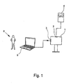
- Fig. 1 an exemplary embodiment of a parameterization system is shown, wherein the interactions between the various elements should be clarified.
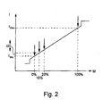
- the graph of Fig. 2 illustrates the way in which the output signals are generated in the way that is usual when transmitting measured values as 4 ... 20 mA signals. Shown is the particular sequence of output signals resulting from the parameterization method according to the invention.
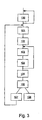
- Fig. 3 finally shows an exemplary sequence of individual steps of the parameterization method according to the invention.
- the Fig. 1 shows a field device 1, which is an example of a level gauge according to the radar principle.
- the field device 1 has an interface 2, which serves as a current output z. B. for connection to a two-wire or to a current loop is used.
- a service interface 3 is provided, set via the parameters or program routines are controlled.
- the service interface 3 is provided here for connection to an electrical conductor.
- the service interface 3 is a direct input unit of the field device, for. B. a touch display.
- the field device 1 is connected for the parameterization with two devices.
- a current measuring device 4 is connected to the interface 2 for the output of current signals, which serves to measure the output signals of the field device 1 in the form of current signals.
- a parameterization unit 5 - here in the form of a portable computer - connected. This results in a total of possibly only temporarily existing system for parameterization of the field device 1 by an operator. 6
- the parameter values of the field device 1 are set via the service interface 3. It is provided in the field device 1 that some parameter values are changeable only after input of an access code or after the setting of special parameters (which thus for example act as a kind of toggle switch). In order to ensure, in particular for safety-critical applications, that the parameter values have been set correctly, the parameter values are read back in the embodiment shown.
- the output of the parameter values via the interface 2 by the generation of output signals as current signals is in particular that the field device 1 z. For example, you do not need to have a suburb ad. The system simply has to pick up and measure a current signal.
- a control value in the field device 1 is determined on the basis of at least one parameter value. This is done, for example, via a suitably stored formula or via stored tables or a combination of both variants. From the control value, the carrier of the information about at least one parameter value or all or at least one possibly by their meaning z. B. is excellent group of parameter values, then at least one output signal is generated in turn via a predetermined assignment and output as a current signal via the interface 2.
- the received or measured here by the ammeter 4 output signal allows the determination of a comparison value, which corresponds to an optimal transmission substantially the control value. Since the generation of the control value occurs on the basis of previously known relationships, a setpoint can be determined by the operator 6, possibly in conjunction with the parameterization unit 5, which, like the control value, reflects the parameter values.
- the operator 6 uses the parameterization unit 5 to acknowledge the parameter values or possibly the complete setting of the field device 1, which can subsequently be used for the measurement in the process.
- the signal width of the current intensity is from 4 mA to 20 mA for the transmission of measured values (M on the X- Axis of the graph), which are located between the smallest measured value (corresponding to 4 mA) and the maximum measured value (corresponding to 20 mA).
- measured values M on the X- Axis of the graph
- a linear relationship can be used within this range between the current value and the measured value.
- a current of 12 mA would therefore mean that a measured value was measured, which lies midway between the smallest and the largest assumed measured value. If a current signal is generated outside this bandwidth, this usually signals the presence of an error, which is why the term residual current exists.
- the control value is scaled accordingly for the transmission as an output signal so that it allows transmission as a 4 ... 20mA signal.
- a plurality of output signals is generated, through which the bandwidth between 4 mA as a minimum current I MIN and 20 mA as the maximum current signal I MAX is traversed.
- the step size is set by way of example with 10% steps. Therefore, possibly due to an interpolation of measured output signals are closed to the control value. Furthermore, if necessary, errors in the transmission can be detected if it is z. B. comes to deviation from the given variation scheme.
- output signals are also generated which are generated outside the normal range, ie, less than 4 mA or greater than 20 mA.
- the Fig. 3 shows a sequence of the steps of the parameterization method, as exemplified in the Fig. 1 represented system or in similarly configured parameterization is realized. However, other steps or further steps within the scope of the invention are possible.
- step 100 a parameter value of the field device is set via the parameterization unit. If necessary, this step 100 is repeated several times if several parameter values are to be set. The access also depends on which parameter values are enabled for an input. In an alternative embodiment, the steps following step 100 are processed for each parameter value entered.
- a control value is determined by the field device on the basis of the currently set parameter values or alternatively of all parameter values that can be entered in the field device, for example by using data from tables stored in the field device and an associated formula that has also been appropriately filed.
- a setpoint value for the parameter values entered is determined on the side of the operator or, in particular, in the parameterization unit. If, in particular, the same algorithm is used for determining the control value and the desired value, and if the parameter values have been correctly transmitted and arrived, then in this ideal case there is a correspondence between the desired value and the control value.
- the setpoints are stored, for example, in a manual.
- control and the setpoint are, for example, additionally dependent on a measured value, insofar as it is the field device - as in the embodiment of Fig. 1 - is a measuring device.
- the linearization takes account of the associated range for the signals and the zero tolerance means a shift of the scale used in each case.
- step 103 the field device generates an output signal as a function of the control value and outputs this as a current signal via a corresponding interface.
- step 104 a suitable current measurement takes place at the used interface of the field device.
- the output signal is output multiple times according to a variation sequence (step 103), and a current value is suitably measured (step 104).
- a comparison value is then determined in step 105, which is compared in step 106 with the desired value. If both values match, then the correct parameter values have been set in the field device and the process can be ended in step 107. If in each case only a subset of the parameter values is read back, then, in the case of the agreement, a return to step 101 takes place, so that the control value can also be determined for other parameter values and the further steps can be carried out. This is repeated accordingly until all predetermined parameter values have been checked.
- a troubleshooting step begins in step 108.
Landscapes
- Engineering & Computer Science (AREA)
- Physics & Mathematics (AREA)
- General Physics & Mathematics (AREA)
- Automation & Control Theory (AREA)
- General Engineering & Computer Science (AREA)
- Human Computer Interaction (AREA)
- Manufacturing & Machinery (AREA)
- Testing And Monitoring For Control Systems (AREA)
- Programmable Controllers (AREA)
- Arrangements For Transmission Of Measured Signals (AREA)
- Feedback Control In General (AREA)
Claims (6)
- Procédé de paramétrage d'un appareil de terrain (1), dans lequel la valeur d'au moins un paramètre de l'appareil de terrain (1) peut être réglée, l'appareil de terrain (1) présentant au moins une interface (2), au moins une valeur de contrôle qui dépend de la valeur du ou des paramètres étant déterminée,
caractérisé en ce que
au moins deux signaux de sortie dépendant au moins de la valeur de contrôle et différents l'un de l'autre sont formés par l'appareil de terrain (1) et sont délivrés sous la forme de signaux de courant sur l'interface (2) de l'appareil de terrain (1), les signaux de sortie étant formés de telle sorte que les signaux de sortie soient situés entre une valeur minimale (IMIN) prédéterminée et une valeur maximale (IMAX) prédéterminée, à une largeur de pas (ΔI) prédéterminée. - Procédé selon la revendication 1, caractérisé en ce qu'au moins un signal de sortie est formé de manière à être situé à l'extérieur d'une plage prédéterminée de signaux.
- Procédé selon les revendications 1 ou 2, caractérisé en ce que l'appareil de terrain (1) est configuré comme appareil de mesure et en ce que la ou les valeurs de contrôle sont formées en fonction d'une valeur de mesure.
- Appareil de terrain (1) présentant au moins une interface (2), la valeur d'au moins un paramètre de l'appareil de terrain (1) pouvant être réglée et l'appareil de terrain (1) déterminant lors d'une paramétrisation au moins une valeur de contrôle qui dépend de la valeur du ou des paramètres,
caractérisé en ce que
l'appareil de terrain (1) forme plusieurs signaux de sortie différents les uns des autres et dépendant au moins de la valeur de contrôle,
en ce que les signaux de sortie sont situés entre une valeur minimale (IMIN) prédéterminée et une valeur maximale (IMAX) prédéterminée, à une largeur de pas (ΔI) prédéterminée et
en ce que l'appareil de terrain (1) délivre les signaux de sortie sous la forme de signaux de courant sur l'interface (2). - Appareil de terrain (1) selon la revendication 4, caractérisé en ce que l'appareil de terrain (1) forme au moins un signal de sortie de telle sorte qu'il soit situé à l'extérieur d'une plage de signaux prédéterminée.
- Appareil de terrain (1) selon les revendications 4 ou 5, caractérisé en ce que l'appareil de terrain (1) est configuré comme appareil de mesure et en ce que l'appareil de terrain (1) forme la ou les valeurs de contrôle en fonction d'une valeur de mesure.
Applications Claiming Priority (1)
| Application Number | Priority Date | Filing Date | Title |
|---|---|---|---|
| DE102012016403.3A DE102012016403B4 (de) | 2012-08-21 | 2012-08-21 | Verfahren zur Parametrierung eines Feldgeräts und entsprechendes Feldgerät und System zur Parametrierung |
Publications (2)
| Publication Number | Publication Date |
|---|---|
| EP2701018A1 EP2701018A1 (fr) | 2014-02-26 |
| EP2701018B1 true EP2701018B1 (fr) | 2015-10-21 |
Family
ID=48325346
Family Applications (1)
| Application Number | Title | Priority Date | Filing Date |
|---|---|---|---|
| EP13002203.1A Active EP2701018B1 (fr) | 2012-08-21 | 2013-04-25 | Procédé de paramétrage sécurisé d'un appareil de terrain |
Country Status (8)
| Country | Link |
|---|---|
| US (1) | US20140058543A1 (fr) |
| EP (1) | EP2701018B1 (fr) |
| JP (1) | JP6124735B2 (fr) |
| KR (1) | KR101764679B1 (fr) |
| CN (1) | CN103631175B (fr) |
| BR (1) | BR102013021196B1 (fr) |
| CA (1) | CA2815628A1 (fr) |
| DE (1) | DE102012016403B4 (fr) |
Families Citing this family (6)
| Publication number | Priority date | Publication date | Assignee | Title |
|---|---|---|---|---|
| DE102015102486B4 (de) * | 2015-02-20 | 2021-01-28 | Krohne Messtechnik Gmbh | Feldgerät zur Bestimmung einer Messgröße und Verfahren zum Kommunizieren |
| EP3273380B1 (fr) | 2016-07-20 | 2018-12-12 | Siemens Healthcare GmbH | Protection de données échangées entre un utilisateur de service et un fournisseur de services |
| DE102017205832A1 (de) * | 2017-04-05 | 2018-10-11 | Siemens Aktiengesellschaft | Verfahren zum Parametrieren eines Feldgeräts sowie parametrierbares Feldgerät |
| EP3493000B1 (fr) * | 2017-12-04 | 2023-06-14 | Siemens Aktiengesellschaft | Procédé de détection de manière protégée contre les erreurs d'une valeur mesurée et système d'automatisation |
| DE102020208610A1 (de) | 2020-07-09 | 2022-01-13 | Robert Bosch Gesellschaft mit beschränkter Haftung | Verfahren und Informationssystem zum Testen einer Eingabeoberfläche zur Eingabe von Steuerparametern für eine Antriebeinheit |
| DE102022101689A1 (de) * | 2022-01-25 | 2023-07-27 | Krohne Messtechnik Gmbh | Verfahren zur Änderung eines Ist-Zugangsschlüssels in einem Feldgerät der Automatisierungstechnik |
Family Cites Families (23)
| Publication number | Priority date | Publication date | Assignee | Title |
|---|---|---|---|---|
| JPH0341831A (ja) * | 1989-07-10 | 1991-02-22 | Hitachi Ltd | フイールド通信方式 |
| ATE187824T1 (de) * | 1994-10-24 | 2000-01-15 | Fisher Rosemount Systems Inc | Vorrichtung, die einen zugang zu feldgeräten in einem verteilten steuerungssystem gestattet |
| DE19622295A1 (de) * | 1996-05-22 | 1997-11-27 | Hartmann & Braun Ag | Anordnung zur Datenübertragung in Prozeßleitsystemen |
| US6959356B2 (en) * | 2001-07-30 | 2005-10-25 | Fisher-Rosemount Systems, Inc. | Multi-protocol field device and communication method |
| US6978186B2 (en) * | 2002-03-22 | 2005-12-20 | International Rectifier Corporation | Modular functional block for an electronic control system |
| JP2003337604A (ja) * | 2002-05-20 | 2003-11-28 | Yamatake Corp | 調節計用パラメータ設定器 |
| DE10234304A1 (de) * | 2002-07-26 | 2004-02-19 | Endress + Hauser Gmbh + Co. Kg | Verfahren zum Aktualisieren von Gerätebeschreibungen für Feldgeräte der Prozessautomatisierungstechnik |
| US7460865B2 (en) * | 2003-06-18 | 2008-12-02 | Fisher-Rosemount Systems, Inc. | Self-configuring communication networks for use with process control systems |
| US7436797B2 (en) * | 2003-06-18 | 2008-10-14 | Fisher-Rosemount Systems, Inc. | Wireless architecture and support for process control systems |
| JP2007536634A (ja) * | 2004-05-04 | 2007-12-13 | フィッシャー−ローズマウント・システムズ・インコーポレーテッド | プロセス制御システムのためのサービス指向型アーキテクチャ |
| DE102004055971B8 (de) | 2004-11-19 | 2012-06-21 | Kw-Software Gmbh | Verfahren und Vorrichtung zur sicheren Parametierung gemäß IEC 61508 SIL 1 bis 3 oder EN 954-1 Kategorie 1 bis 4 |
| DE102006013827A1 (de) * | 2006-03-23 | 2007-09-27 | Endress + Hauser Flowtec Ag | Verfahren zur benutzerspezifischen Anpassung eines Feldgerätes der Automatisierungstechnik |
| DE102006024311A1 (de) * | 2006-05-24 | 2007-11-29 | Berthold Technologies Gmbh & Co. Kg | Schaltung zur Übermittlung eines analogen Signalwertes |
| US8140279B2 (en) * | 2007-09-24 | 2012-03-20 | Budderfly Ventures, Llc | Computer based energy management |
| DE102009001863A1 (de) * | 2009-03-25 | 2010-09-30 | Endress + Hauser Conducta Gesellschaft für Mess- und Regeltechnik mbH + Co. KG | Verfahren und Schaltung zur Signalübertragung über eine Stromschleife |
| JP2010258865A (ja) * | 2009-04-27 | 2010-11-11 | Yokogawa Electric Corp | フィールド機器 |
| EP2246761B1 (fr) * | 2009-04-30 | 2012-08-29 | Siemens Aktiengesellschaft | Procédé de modifications assurées des paramètres d'un composant d'automatisation industriel protégé contre les erreurs |
| US8127060B2 (en) * | 2009-05-29 | 2012-02-28 | Invensys Systems, Inc | Methods and apparatus for control configuration with control objects that are fieldbus protocol-aware |
| EP2341406B1 (fr) * | 2009-12-23 | 2012-10-31 | Siemens Aktiengesellschaft | Procédé pour paramétrisation sécurisée d'un dispositif électrique |
| JP5056880B2 (ja) * | 2010-03-24 | 2012-10-24 | 横河電機株式会社 | フィールド機器メンテナンスシステム |
| JP5578364B2 (ja) * | 2010-11-10 | 2014-08-27 | 横河電機株式会社 | ハート通信システム |
| DE102010062908B4 (de) * | 2010-12-13 | 2012-10-31 | Siemens Aktiengesellschaft | Verfahren zum Parametrisieren eines Gerätes, parametrisierbares Gerät und Parametrisierungsvorrlchtung |
| DE102012002013B4 (de) * | 2012-02-03 | 2015-09-10 | Krohne Messtechnik Gmbh | Prüfung einer Messgerätanordnung, entsprechende Messgerätanordnung und Prüfanordnung |
-
2012
- 2012-08-21 DE DE102012016403.3A patent/DE102012016403B4/de not_active Expired - Fee Related
- 2012-11-20 US US13/682,003 patent/US20140058543A1/en not_active Abandoned
-
2013
- 2013-04-25 EP EP13002203.1A patent/EP2701018B1/fr active Active
- 2013-05-13 CA CA2815628A patent/CA2815628A1/fr not_active Abandoned
- 2013-08-19 KR KR1020130098006A patent/KR101764679B1/ko not_active Expired - Fee Related
- 2013-08-20 BR BR102013021196-6A patent/BR102013021196B1/pt not_active IP Right Cessation
- 2013-08-21 CN CN201310365395.0A patent/CN103631175B/zh not_active Expired - Fee Related
- 2013-08-21 JP JP2013171146A patent/JP6124735B2/ja not_active Expired - Fee Related
Also Published As
| Publication number | Publication date |
|---|---|
| JP6124735B2 (ja) | 2017-05-10 |
| CN103631175B (zh) | 2018-01-16 |
| CA2815628A1 (fr) | 2014-02-21 |
| CN103631175A (zh) | 2014-03-12 |
| DE102012016403A1 (de) | 2014-02-27 |
| JP2014041613A (ja) | 2014-03-06 |
| US20140058543A1 (en) | 2014-02-27 |
| DE102012016403B4 (de) | 2014-10-30 |
| BR102013021196B1 (pt) | 2020-09-15 |
| KR101764679B1 (ko) | 2017-08-03 |
| EP2701018A1 (fr) | 2014-02-26 |
| KR20140024815A (ko) | 2014-03-03 |
| BR102013021196A2 (pt) | 2014-12-23 |
Similar Documents
| Publication | Publication Date | Title |
|---|---|---|
| EP2701018B1 (fr) | Procédé de paramétrage sécurisé d'un appareil de terrain | |
| EP2425308B1 (fr) | Dispositif et procédé pour analyser un résidu afin de détecter des erreurs de comportement dans un système d'avion | |
| EP3745217B1 (fr) | Dispositif de surveillance d' un système de traitement et de transmission de données. | |
| EP3283928B1 (fr) | Procédé de branchement ou de débranchement automatique d'une résistance de communication d'un dispositif hart | |
| EP2613462B1 (fr) | Procédé destiné à la surveillance d'un émetteur et émetteur correspondant | |
| DE102012016406B4 (de) | Verfahren zur Parametrierung eines Feldgerätes und entsprechendes System zur Parametrierung | |
| DE102012109132A1 (de) | Verbessertes Verfahren und verbesserte Vorrichtung zur Vermeidung von Aliasing | |
| DE102014016180A1 (de) | Verfahren und Einrichtung zur Verwaltung und Konfiguration von Feldgeräten einer Automatisierungsanlage | |
| EP2835700B1 (fr) | Procédé de paramétrage d'un appareil de terrain | |
| EP3470939B1 (fr) | Procédé et système de surveillance de l'intégrité de sécurité d'une fonction de sécurité fournie par un système de sécurité | |
| EP2622417A2 (fr) | Procédé de récupération destiné à un appareil comportant une sortie de courant analogique pour l'émission d'une valeur de mesure ou d'une valeur de réglage | |
| EP3622403A2 (fr) | Procédé pour le contrôle automatisé assisté par ordinateur de descriptions | |
| DE102018217118A1 (de) | Verfahren zum Erstellen einer Fehlerdiagnose eines Antriebsstrangs eines elektrisch betriebenen Kraftfahrzeugs und Kraftfahrzeug | |
| WO2016026620A1 (fr) | Procédé de test d'un appareil de terrain | |
| EP2283426B1 (fr) | Procédé et dispositif permettant de corriger des informations transmises sous forme numérique | |
| EP2432141B1 (fr) | Procédé de surveillance du fonctionnement d'un réseau de communication | |
| WO2013053559A1 (fr) | Procédé de transmission de données sous forme de télégramme | |
| EP4425390A1 (fr) | Apprentissage automatique supervisé d'un processus mis en oeuvre par ordinateur pour effectuer un processus technique | |
| DE102018105872A1 (de) | Verfahren zur Analyse einer Kommunikationsqualität | |
| EP4425385A1 (fr) | Apprentissage automatique supervisé d'un processus mis en oeuvre par ordinateur pour effectuer un processus technique | |
| EP3671378A1 (fr) | Contenant de données pour un système de commande d'une installation technique | |
| DE102017217835A1 (de) | Signalverarbeitungsverfahren und -vorrichtung | |
| EP3076249A1 (fr) | Procede de fonctionnement d'un appareil de terrain et appareil de terrain correspondant | |
| DE102015200721A1 (de) | Verfahren zum Verarbeiten von zumindest einer Information in einem vernetzten System |
Legal Events
| Date | Code | Title | Description |
|---|---|---|---|
| PUAI | Public reference made under article 153(3) epc to a published international application that has entered the european phase |
Free format text: ORIGINAL CODE: 0009012 |
|
| AK | Designated contracting states |
Kind code of ref document: A1 Designated state(s): AL AT BE BG CH CY CZ DE DK EE ES FI FR GB GR HR HU IE IS IT LI LT LU LV MC MK MT NL NO PL PT RO RS SE SI SK SM TR |
|
| AX | Request for extension of the european patent |
Extension state: BA ME |
|
| 17P | Request for examination filed |
Effective date: 20140318 |
|
| RBV | Designated contracting states (corrected) |
Designated state(s): AL AT BE BG CH CY CZ DE DK EE ES FI FR GB GR HR HU IE IS IT LI LT LU LV MC MK MT NL NO PL PT RO RS SE SI SK SM TR |
|
| 17Q | First examination report despatched |
Effective date: 20140909 |
|
| GRAP | Despatch of communication of intention to grant a patent |
Free format text: ORIGINAL CODE: EPIDOSNIGR1 |
|
| INTG | Intention to grant announced |
Effective date: 20150518 |
|
| GRAS | Grant fee paid |
Free format text: ORIGINAL CODE: EPIDOSNIGR3 |
|
| GRAA | (expected) grant |
Free format text: ORIGINAL CODE: 0009210 |
|
| AK | Designated contracting states |
Kind code of ref document: B1 Designated state(s): AL AT BE BG CH CY CZ DE DK EE ES FI FR GB GR HR HU IE IS IT LI LT LU LV MC MK MT NL NO PL PT RO RS SE SI SK SM TR |
|
| REG | Reference to a national code |
Ref country code: GB Ref legal event code: FG4D Free format text: NOT ENGLISH |
|
| REG | Reference to a national code |
Ref country code: CH Ref legal event code: EP |
|
| REG | Reference to a national code |
Ref country code: AT Ref legal event code: REF Ref document number: 756974 Country of ref document: AT Kind code of ref document: T Effective date: 20151115 |
|
| REG | Reference to a national code |
Ref country code: IE Ref legal event code: FG4D Free format text: LANGUAGE OF EP DOCUMENT: GERMAN |
|
| REG | Reference to a national code |
Ref country code: DE Ref legal event code: R096 Ref document number: 502013001354 Country of ref document: DE |
|
| REG | Reference to a national code |
Ref country code: LT Ref legal event code: MG4D |
|
| REG | Reference to a national code |
Ref country code: NL Ref legal event code: FP |
|
| REG | Reference to a national code |
Ref country code: FR Ref legal event code: PLFP Year of fee payment: 4 |
|
| PG25 | Lapsed in a contracting state [announced via postgrant information from national office to epo] |
Ref country code: IT Free format text: LAPSE BECAUSE OF FAILURE TO SUBMIT A TRANSLATION OF THE DESCRIPTION OR TO PAY THE FEE WITHIN THE PRESCRIBED TIME-LIMIT Effective date: 20151021 Ref country code: NO Free format text: LAPSE BECAUSE OF FAILURE TO SUBMIT A TRANSLATION OF THE DESCRIPTION OR TO PAY THE FEE WITHIN THE PRESCRIBED TIME-LIMIT Effective date: 20160121 Ref country code: IS Free format text: LAPSE BECAUSE OF FAILURE TO SUBMIT A TRANSLATION OF THE DESCRIPTION OR TO PAY THE FEE WITHIN THE PRESCRIBED TIME-LIMIT Effective date: 20160221 Ref country code: HR Free format text: LAPSE BECAUSE OF FAILURE TO SUBMIT A TRANSLATION OF THE DESCRIPTION OR TO PAY THE FEE WITHIN THE PRESCRIBED TIME-LIMIT Effective date: 20151021 Ref country code: LT Free format text: LAPSE BECAUSE OF FAILURE TO SUBMIT A TRANSLATION OF THE DESCRIPTION OR TO PAY THE FEE WITHIN THE PRESCRIBED TIME-LIMIT Effective date: 20151021 Ref country code: ES Free format text: LAPSE BECAUSE OF FAILURE TO SUBMIT A TRANSLATION OF THE DESCRIPTION OR TO PAY THE FEE WITHIN THE PRESCRIBED TIME-LIMIT Effective date: 20151021 |
|
| PG25 | Lapsed in a contracting state [announced via postgrant information from national office to epo] |
Ref country code: PT Free format text: LAPSE BECAUSE OF FAILURE TO SUBMIT A TRANSLATION OF THE DESCRIPTION OR TO PAY THE FEE WITHIN THE PRESCRIBED TIME-LIMIT Effective date: 20160222 Ref country code: GR Free format text: LAPSE BECAUSE OF FAILURE TO SUBMIT A TRANSLATION OF THE DESCRIPTION OR TO PAY THE FEE WITHIN THE PRESCRIBED TIME-LIMIT Effective date: 20160122 Ref country code: SE Free format text: LAPSE BECAUSE OF FAILURE TO SUBMIT A TRANSLATION OF THE DESCRIPTION OR TO PAY THE FEE WITHIN THE PRESCRIBED TIME-LIMIT Effective date: 20151021 Ref country code: LV Free format text: LAPSE BECAUSE OF FAILURE TO SUBMIT A TRANSLATION OF THE DESCRIPTION OR TO PAY THE FEE WITHIN THE PRESCRIBED TIME-LIMIT Effective date: 20151021 Ref country code: RS Free format text: LAPSE BECAUSE OF FAILURE TO SUBMIT A TRANSLATION OF THE DESCRIPTION OR TO PAY THE FEE WITHIN THE PRESCRIBED TIME-LIMIT Effective date: 20151021 Ref country code: PL Free format text: LAPSE BECAUSE OF FAILURE TO SUBMIT A TRANSLATION OF THE DESCRIPTION OR TO PAY THE FEE WITHIN THE PRESCRIBED TIME-LIMIT Effective date: 20151021 Ref country code: FI Free format text: LAPSE BECAUSE OF FAILURE TO SUBMIT A TRANSLATION OF THE DESCRIPTION OR TO PAY THE FEE WITHIN THE PRESCRIBED TIME-LIMIT Effective date: 20151021 |
|
| REG | Reference to a national code |
Ref country code: DE Ref legal event code: R097 Ref document number: 502013001354 Country of ref document: DE |
|
| PG25 | Lapsed in a contracting state [announced via postgrant information from national office to epo] |
Ref country code: CZ Free format text: LAPSE BECAUSE OF FAILURE TO SUBMIT A TRANSLATION OF THE DESCRIPTION OR TO PAY THE FEE WITHIN THE PRESCRIBED TIME-LIMIT Effective date: 20151021 |
|
| PLBE | No opposition filed within time limit |
Free format text: ORIGINAL CODE: 0009261 |
|
| STAA | Information on the status of an ep patent application or granted ep patent |
Free format text: STATUS: NO OPPOSITION FILED WITHIN TIME LIMIT |
|
| PG25 | Lapsed in a contracting state [announced via postgrant information from national office to epo] |
Ref country code: SM Free format text: LAPSE BECAUSE OF FAILURE TO SUBMIT A TRANSLATION OF THE DESCRIPTION OR TO PAY THE FEE WITHIN THE PRESCRIBED TIME-LIMIT Effective date: 20151021 Ref country code: RO Free format text: LAPSE BECAUSE OF FAILURE TO SUBMIT A TRANSLATION OF THE DESCRIPTION OR TO PAY THE FEE WITHIN THE PRESCRIBED TIME-LIMIT Effective date: 20151021 Ref country code: DK Free format text: LAPSE BECAUSE OF FAILURE TO SUBMIT A TRANSLATION OF THE DESCRIPTION OR TO PAY THE FEE WITHIN THE PRESCRIBED TIME-LIMIT Effective date: 20151021 Ref country code: SK Free format text: LAPSE BECAUSE OF FAILURE TO SUBMIT A TRANSLATION OF THE DESCRIPTION OR TO PAY THE FEE WITHIN THE PRESCRIBED TIME-LIMIT Effective date: 20151021 Ref country code: BE Free format text: LAPSE BECAUSE OF NON-PAYMENT OF DUE FEES Effective date: 20160430 Ref country code: EE Free format text: LAPSE BECAUSE OF FAILURE TO SUBMIT A TRANSLATION OF THE DESCRIPTION OR TO PAY THE FEE WITHIN THE PRESCRIBED TIME-LIMIT Effective date: 20151021 |
|
| 26N | No opposition filed |
Effective date: 20160722 |
|
| PG25 | Lapsed in a contracting state [announced via postgrant information from national office to epo] |
Ref country code: SI Free format text: LAPSE BECAUSE OF FAILURE TO SUBMIT A TRANSLATION OF THE DESCRIPTION OR TO PAY THE FEE WITHIN THE PRESCRIBED TIME-LIMIT Effective date: 20151021 |
|
| PG25 | Lapsed in a contracting state [announced via postgrant information from national office to epo] |
Ref country code: LU Free format text: LAPSE BECAUSE OF FAILURE TO SUBMIT A TRANSLATION OF THE DESCRIPTION OR TO PAY THE FEE WITHIN THE PRESCRIBED TIME-LIMIT Effective date: 20160425 |
|
| REG | Reference to a national code |
Ref country code: IE Ref legal event code: MM4A |
|
| REG | Reference to a national code |
Ref country code: FR Ref legal event code: PLFP Year of fee payment: 5 |
|
| PG25 | Lapsed in a contracting state [announced via postgrant information from national office to epo] |
Ref country code: IE Free format text: LAPSE BECAUSE OF NON-PAYMENT OF DUE FEES Effective date: 20160425 |
|
| REG | Reference to a national code |
Ref country code: FR Ref legal event code: PLFP Year of fee payment: 6 |
|
| PG25 | Lapsed in a contracting state [announced via postgrant information from national office to epo] |
Ref country code: CY Free format text: LAPSE BECAUSE OF FAILURE TO SUBMIT A TRANSLATION OF THE DESCRIPTION OR TO PAY THE FEE WITHIN THE PRESCRIBED TIME-LIMIT Effective date: 20151021 Ref country code: HU Free format text: LAPSE BECAUSE OF FAILURE TO SUBMIT A TRANSLATION OF THE DESCRIPTION OR TO PAY THE FEE WITHIN THE PRESCRIBED TIME-LIMIT; INVALID AB INITIO Effective date: 20130425 |
|
| PG25 | Lapsed in a contracting state [announced via postgrant information from national office to epo] |
Ref country code: MK Free format text: LAPSE BECAUSE OF FAILURE TO SUBMIT A TRANSLATION OF THE DESCRIPTION OR TO PAY THE FEE WITHIN THE PRESCRIBED TIME-LIMIT Effective date: 20151021 Ref country code: MT Free format text: LAPSE BECAUSE OF FAILURE TO SUBMIT A TRANSLATION OF THE DESCRIPTION OR TO PAY THE FEE WITHIN THE PRESCRIBED TIME-LIMIT Effective date: 20151021 Ref country code: TR Free format text: LAPSE BECAUSE OF FAILURE TO SUBMIT A TRANSLATION OF THE DESCRIPTION OR TO PAY THE FEE WITHIN THE PRESCRIBED TIME-LIMIT Effective date: 20151021 Ref country code: MC Free format text: LAPSE BECAUSE OF FAILURE TO SUBMIT A TRANSLATION OF THE DESCRIPTION OR TO PAY THE FEE WITHIN THE PRESCRIBED TIME-LIMIT Effective date: 20151021 |
|
| PG25 | Lapsed in a contracting state [announced via postgrant information from national office to epo] |
Ref country code: BG Free format text: LAPSE BECAUSE OF FAILURE TO SUBMIT A TRANSLATION OF THE DESCRIPTION OR TO PAY THE FEE WITHIN THE PRESCRIBED TIME-LIMIT Effective date: 20151021 |
|
| PG25 | Lapsed in a contracting state [announced via postgrant information from national office to epo] |
Ref country code: AL Free format text: LAPSE BECAUSE OF FAILURE TO SUBMIT A TRANSLATION OF THE DESCRIPTION OR TO PAY THE FEE WITHIN THE PRESCRIBED TIME-LIMIT Effective date: 20151021 |
|
| REG | Reference to a national code |
Ref country code: AT Ref legal event code: MM01 Ref document number: 756974 Country of ref document: AT Kind code of ref document: T Effective date: 20180425 |
|
| PG25 | Lapsed in a contracting state [announced via postgrant information from national office to epo] |
Ref country code: AT Free format text: LAPSE BECAUSE OF NON-PAYMENT OF DUE FEES Effective date: 20180425 |
|
| PGFP | Annual fee paid to national office [announced via postgrant information from national office to epo] |
Ref country code: NL Payment date: 20230419 Year of fee payment: 11 |
|
| P01 | Opt-out of the competence of the unified patent court (upc) registered |
Effective date: 20230607 |
|
| PGFP | Annual fee paid to national office [announced via postgrant information from national office to epo] |
Ref country code: FR Payment date: 20230424 Year of fee payment: 11 Ref country code: DE Payment date: 20230620 Year of fee payment: 11 Ref country code: CH Payment date: 20230502 Year of fee payment: 11 |
|
| PGFP | Annual fee paid to national office [announced via postgrant information from national office to epo] |
Ref country code: GB Payment date: 20230419 Year of fee payment: 11 |
|
| REG | Reference to a national code |
Ref country code: DE Ref legal event code: R119 Ref document number: 502013001354 Country of ref document: DE |
|
| REG | Reference to a national code |
Ref country code: CH Ref legal event code: PL |
|
| REG | Reference to a national code |
Ref country code: NL Ref legal event code: MM Effective date: 20240501 |
|
| GBPC | Gb: european patent ceased through non-payment of renewal fee |
Effective date: 20240425 |
|
| PG25 | Lapsed in a contracting state [announced via postgrant information from national office to epo] |
Ref country code: DE Free format text: LAPSE BECAUSE OF NON-PAYMENT OF DUE FEES Effective date: 20241105 |
|
| PG25 | Lapsed in a contracting state [announced via postgrant information from national office to epo] |
Ref country code: NL Free format text: LAPSE BECAUSE OF NON-PAYMENT OF DUE FEES Effective date: 20240501 |
|
| PG25 | Lapsed in a contracting state [announced via postgrant information from national office to epo] |
Ref country code: GB Free format text: LAPSE BECAUSE OF NON-PAYMENT OF DUE FEES Effective date: 20240425 |
|
| PG25 | Lapsed in a contracting state [announced via postgrant information from national office to epo] |
Ref country code: FR Free format text: LAPSE BECAUSE OF NON-PAYMENT OF DUE FEES Effective date: 20240430 |
|
| PG25 | Lapsed in a contracting state [announced via postgrant information from national office to epo] |
Ref country code: NL Free format text: LAPSE BECAUSE OF NON-PAYMENT OF DUE FEES Effective date: 20240501 Ref country code: GB Free format text: LAPSE BECAUSE OF NON-PAYMENT OF DUE FEES Effective date: 20240425 Ref country code: FR Free format text: LAPSE BECAUSE OF NON-PAYMENT OF DUE FEES Effective date: 20240430 Ref country code: DE Free format text: LAPSE BECAUSE OF NON-PAYMENT OF DUE FEES Effective date: 20241105 Ref country code: CH Free format text: LAPSE BECAUSE OF NON-PAYMENT OF DUE FEES Effective date: 20240430 |