EP2701224B1 - Haftdichtungselement für brennstoffzellen - Google Patents
Haftdichtungselement für brennstoffzellen Download PDFInfo
- Publication number
- EP2701224B1 EP2701224B1 EP12774093.4A EP12774093A EP2701224B1 EP 2701224 B1 EP2701224 B1 EP 2701224B1 EP 12774093 A EP12774093 A EP 12774093A EP 2701224 B1 EP2701224 B1 EP 2701224B1
- Authority
- EP
- European Patent Office
- Prior art keywords
- seal member
- adhesive seal
- mass
- fuel cell
- rubber
- Prior art date
- Legal status (The legal status is an assumption and is not a legal conclusion. Google has not performed a legal analysis and makes no representation as to the accuracy of the status listed.)
- Active
Links
Images


Classifications
-
- H—ELECTRICITY
- H01—ELECTRIC ELEMENTS
- H01M—PROCESSES OR MEANS, e.g. BATTERIES, FOR THE DIRECT CONVERSION OF CHEMICAL ENERGY INTO ELECTRICAL ENERGY
- H01M8/00—Fuel cells; Manufacture thereof
- H01M8/02—Details
- H01M8/0271—Sealing or supporting means around electrodes, matrices or membranes
- H01M8/028—Sealing means characterised by their material
- H01M8/0284—Organic resins; Organic polymers
-
- C—CHEMISTRY; METALLURGY
- C08—ORGANIC MACROMOLECULAR COMPOUNDS; THEIR PREPARATION OR CHEMICAL WORKING-UP; COMPOSITIONS BASED THEREON
- C08L—COMPOSITIONS OF MACROMOLECULAR COMPOUNDS
- C08L23/00—Compositions of homopolymers or copolymers of unsaturated aliphatic hydrocarbons having only one carbon-to-carbon double bond; Compositions of derivatives of such polymers
- C08L23/02—Compositions of homopolymers or copolymers of unsaturated aliphatic hydrocarbons having only one carbon-to-carbon double bond; Compositions of derivatives of such polymers not modified by chemical after-treatment
- C08L23/16—Ethylene-propylene or ethylene-propylene-diene copolymers
-
- H—ELECTRICITY
- H01—ELECTRIC ELEMENTS
- H01M—PROCESSES OR MEANS, e.g. BATTERIES, FOR THE DIRECT CONVERSION OF CHEMICAL ENERGY INTO ELECTRICAL ENERGY
- H01M8/00—Fuel cells; Manufacture thereof
- H01M8/02—Details
- H01M8/0202—Collectors; Separators, e.g. bipolar separators; Interconnectors
- H01M8/0258—Collectors; Separators, e.g. bipolar separators; Interconnectors characterised by the configuration of channels, e.g. by the flow field of the reactant or coolant
- H01M8/026—Collectors; Separators, e.g. bipolar separators; Interconnectors characterised by the configuration of channels, e.g. by the flow field of the reactant or coolant characterised by grooves, e.g. their pitch or depth
-
- H—ELECTRICITY
- H01—ELECTRIC ELEMENTS
- H01M—PROCESSES OR MEANS, e.g. BATTERIES, FOR THE DIRECT CONVERSION OF CHEMICAL ENERGY INTO ELECTRICAL ENERGY
- H01M8/00—Fuel cells; Manufacture thereof
- H01M8/02—Details
- H01M8/0202—Collectors; Separators, e.g. bipolar separators; Interconnectors
- H01M8/0267—Collectors; Separators, e.g. bipolar separators; Interconnectors having heating or cooling means, e.g. heaters or coolant flow channels
-
- H—ELECTRICITY
- H01—ELECTRIC ELEMENTS
- H01M—PROCESSES OR MEANS, e.g. BATTERIES, FOR THE DIRECT CONVERSION OF CHEMICAL ENERGY INTO ELECTRICAL ENERGY
- H01M8/00—Fuel cells; Manufacture thereof
- H01M8/02—Details
- H01M8/0271—Sealing or supporting means around electrodes, matrices or membranes
-
- H—ELECTRICITY
- H01—ELECTRIC ELEMENTS
- H01M—PROCESSES OR MEANS, e.g. BATTERIES, FOR THE DIRECT CONVERSION OF CHEMICAL ENERGY INTO ELECTRICAL ENERGY
- H01M8/00—Fuel cells; Manufacture thereof
- H01M8/02—Details
- H01M8/0271—Sealing or supporting means around electrodes, matrices or membranes
- H01M8/0276—Sealing means characterised by their form
-
- H—ELECTRICITY
- H01—ELECTRIC ELEMENTS
- H01M—PROCESSES OR MEANS, e.g. BATTERIES, FOR THE DIRECT CONVERSION OF CHEMICAL ENERGY INTO ELECTRICAL ENERGY
- H01M8/00—Fuel cells; Manufacture thereof
- H01M8/24—Grouping of fuel cells, e.g. stacking of fuel cells
- H01M8/241—Grouping of fuel cells, e.g. stacking of fuel cells with solid or matrix-supported electrolytes
-
- H—ELECTRICITY
- H01—ELECTRIC ELEMENTS
- H01M—PROCESSES OR MEANS, e.g. BATTERIES, FOR THE DIRECT CONVERSION OF CHEMICAL ENERGY INTO ELECTRICAL ENERGY
- H01M8/00—Fuel cells; Manufacture thereof
- H01M8/24—Grouping of fuel cells, e.g. stacking of fuel cells
- H01M8/2457—Grouping of fuel cells, e.g. stacking of fuel cells with both reactants being gaseous or vaporised
-
- C—CHEMISTRY; METALLURGY
- C08—ORGANIC MACROMOLECULAR COMPOUNDS; THEIR PREPARATION OR CHEMICAL WORKING-UP; COMPOSITIONS BASED THEREON
- C08K—Use of inorganic or non-macromolecular organic substances as compounding ingredients
- C08K5/00—Use of organic ingredients
- C08K5/04—Oxygen-containing compounds
- C08K5/14—Peroxides
-
- Y—GENERAL TAGGING OF NEW TECHNOLOGICAL DEVELOPMENTS; GENERAL TAGGING OF CROSS-SECTIONAL TECHNOLOGIES SPANNING OVER SEVERAL SECTIONS OF THE IPC; TECHNICAL SUBJECTS COVERED BY FORMER USPC CROSS-REFERENCE ART COLLECTIONS [XRACs] AND DIGESTS
- Y02—TECHNOLOGIES OR APPLICATIONS FOR MITIGATION OR ADAPTATION AGAINST CLIMATE CHANGE
- Y02E—REDUCTION OF GREENHOUSE GAS [GHG] EMISSIONS, RELATED TO ENERGY GENERATION, TRANSMISSION OR DISTRIBUTION
- Y02E60/00—Enabling technologies; Technologies with a potential or indirect contribution to GHG emissions mitigation
- Y02E60/30—Hydrogen technology
- Y02E60/50—Fuel cells
Definitions
- the present invention relates to an adhesive seal member for sealing component members of a fuel cell and more specifically relates to an adhesive seal member having good sealing performance at an extremely low temperature.
- a fuel cell generating electricity by electrochemical reaction of gases has high power generation efficiency, exhausts clean gas, and has little impact on the environment.
- a polymer electrolyte fuel cell can be operated at a relatively low temperature and has a large output density.
- the polymer electrolyte fuel cell is expected to be applied to various fields, for example, electric power generation and a power supply for automobiles.
- the polymer electrolyte fuel cell includes a cell in which a membrane electrode assembly (MEA) and others are sandwiched by separators, as a power generation unit.
- the MEA includes a polymer membrane (electrolyte membrane) to be an electrolyte and a pair of electrode catalyst layers (a fuel electrode (anode) catalyst layer and an oxygen electrode (cathode) catalyst layer) that are disposed on both faces of the electrolyte membrane in a thickness direction.
- porous layers are disposed in order to diffuse gas.
- a fuel gas such as hydrogen
- an oxidant gas such as oxygen and air is supplied.
- Electrochemical reaction on a triple phase boundary between the supplied gas, the electrolyte, and the electrode catalyst layer generates electric power.
- a large number of the cells are stacked to form a cell stack, and the cell stack is clamped with end plates or the like that are disposed on both ends of the cell stack in the cell stacking direction.
- the separator includes a flow path of a gas supplied to each electrode and a flow path of a refrigerant for reducing heat generated during power generation.
- a gas supplied to each electrode When gases supplied to the respective electrodes are mixed, problems in which, for example, power generation efficiency is reduced are raised.
- An electrolyte membrane containing water has proton conductivity.
- the electrolyte membrane is required to be maintained in a wet condition. Therefore, in order that a wet condition is maintained in the cell and the mixing of gases and the leakage of gases and a refrigerant are suppressed, it is important to ensure the sealing performance around the MEA and the porous layers and between adjacent separators.
- Patent Documents 1 and 2 disclose a rubber material using ethylene-propylene rubber (EPM), ethylene-propylene-diene rubber (EPDM), or other types of rubber.
- a polymer membrane such as a perfluorinated sulfonic acid membrane is used.
- a rubber composition is disposed close to the electrolyte membrane and is cross-linked and bonded, consideration must be given so that the electrolyte membrane is not deteriorated by heat during cross-linking. In other words, it is desired to perform the cross-linking and adhesion process of a seal member at a lower temperature and for a shorter period of time.
- Patent Documents 1 and 2 disclose seal members including rubber compositions that can be cross-linked at a low temperature of 130°C or less for a comparatively short period of time.
- the seal member is applicable close to an electrolyte membrane.
- the seal member also contains an adhesive component.
- the seal member can be bonded to a member without using an additional adhesive.
- the rubber elasticity of an EPM or EPDM may be lost.
- the present invention has an object to provide an adhesive seal member for a fuel cell capable of being cross-linked at a low temperature and for a short period of time and having good sealing performance even at an extremely low temperature.
- an adhesive seal member for a fuel cell of the present invention is characterized by sealing a component member in the fuel cell and by including a cross-linked product of a rubber composition containing components (A) to (D): (A) at least one rubber component selected from ethylene-propylene rubber and ethylene-propylene-diene rubber having an ethylene content of 40% by mass or more and less than 50% by mass, (B) an organic peroxide having a one-hour half-life temperature of 130°C or less, (C) a crosslinking aid, and (D) at least one adhesive component selected from a resorcinol compound and a melamine compound, an aluminate coupling agent, and a silane coupling agent.
- a rubber composition containing components (A) to (D): (A) at least one rubber component selected from ethylene-propylene rubber and ethylene-propylene-diene rubber having an ethylene content of 40% by mass or more and less than 50% by mass, (B) an organic peroxide having a one
- the adhesive seal member of the present invention limits the ethylene content in the EPM and the EPDM used as the rubber component.
- An EPM and EPDM having a lower ethylene content are unlikely to be crystallized at an extremely low temperature of about -20°C to -30°C.
- rubber elasticity is unlikely to be lowered even at an extremely low temperature.
- the adhesive seal member of the present invention uses at least one of an EPM and an EPDM having a small ethylene content of 40% by mass or more and less than 50% by mass as the rubber component.
- the adhesive seal member can maintain the rubber elasticity at an extremely low temperature even when the softener is not contained. Therefore, the adhesive seal member of the present invention is excellent in sealing performance even at an extremely low temperature.
- the adhesive seal member of the present invention contains the adhesive component (the component (D)).
- the adhesive seal member of the present invention can be bonded to a member without using an additional adhesive.
- the melamine compound serves as a methylene donor and the resorcinol compound serves as a methylene acceptor.
- the donation of a methylene group leads to the formation of each chemical bond between the resorcinol compound and the rubber component and between the resorcinol compound and a member intended to be bonded.
- the rubber component (adhesive seal member) and the member are bonded.
- the adhesive seal member and a member are bonded through the aluminate coupling agent.
- a silane coupling agent is contained as the adhesive component, the adhesive seal member and a member are bonded through the silane coupling agent.
- the adhesive seal member of the present invention ensures good sealing performance even when a fuel cell is operated for a long period of time. In other words, the adhesive seal member can improve the operation reliability of a fuel cell.
- the "sealing a component member in a fuel cell” means sealing the periphery of a component member and the space between component members.
- the adhesive seal member of the present invention has rubber elasticity in a wide temperature range from the operating temperature of a fuel cell to about -30°C.
- the adhesive seal member of the present invention enables not only the sealing due to adhesion but also the sealing due to stress.
- the adhesive seal member of the present invention may be bonded to one member alone and the space between the adhesive seal member and the other member may be sealed by stress.
- the adhesive seal member of the present invention may be bonded to each member, thereby sealing the space between the members by adhesion.
- the sealing performance is likely to be lowered in the stress sealing as compared with the adhesion sealing.
- the adhesive seal member of the present invention maintains the rubber elasticity even at an extremely low temperature and thus the sealing performance is unlikely to be lowered even in the stress sealing.
- the adhesive seal member of the present invention uses an organic peroxide having a one-hour half-life temperature of 130°C or less as the cross-linking agent (the component (B)).
- the "half-life” is time until the initial concentration of an organic peroxide is halved.
- the "half-life temperature” is an index showing a decomposition temperature of an organic peroxide.
- the "one-hour half-life temperature” is a temperature at which the half-life is one hour. In other words, a compound having a lower one-hour half-life temperature is readily decomposed at a low temperature.
- the cross-linking can be performed at a lower temperature (specifically 150°C or less) and for a shorter period of time. Therefore, the adhesive seal member of the present invention can be used, for example, even close to the electrolyte membrane in a polymer electrolyte fuel cell.
- an adhesive seal member for a fuel cell of the present invention will now be described.
- the adhesive seal member for a fuel cell of the present invention is not limited to the following embodiments and may be achieved in various embodiments in which changes and modifications have been made by those skilled in the art without departing from the scope of the present invention.
- the adhesive seal member of the present invention includes a cross-linked product of a rubber composition containing the components (A) to (D). First, a rubber component as the component (A) will be described.
- the rubber component used in the adhesive seal member of the present invention is at least one selected from ethylene-propylene rubber (EPM) and ethylene-propylene-diene rubber (EPDM) having an ethylene content of 40% by mass or more and less than 50% by mass.
- EPM ethylene-propylene rubber
- EPDM ethylene-propylene-diene rubber
- One of the EPM and the EPDM may be used and a mixture of them may be used as long as the ethylene content is 40% by mass or more and less than 50% by mass.
- Two or more pieces of rubber that are the same kind but have, for example, different ethylene contents may be used as a mixture.
- the rubber component desirably contains an EPDM in consideration of acid resistance and water resistance in the operating environment of a fuel cell.
- an EPM or EPDM having an ethylene content of less than 50% by mass is necessary. Meanwhile, an EPM and EPDM having an excessively low ethylene content may have lowered rubber physical properties. Therefore, according to the invention an EPM or EPDM having an ethylene content of 40% by mass or more is used as the rubber component so that elongation and tensile strength required for an adhesive seal member are ensured.
- an organic peroxide as the component (B) will be described.
- the organic peroxide having a one-hour half-life temperature of 130°C or less include a peroxyketal, a peroxyester, a diacyl peroxide, and a peroxydicarbonate.
- at least one of peroxyketals and peroxyesters having a one-hour half-life temperature of 100°C or more is desirably adopted because such a compound is readily cross-linked at a temperature of about 130°C and a rubber composition obtained by kneading the compound together with a cross-linking agent has excellent handleability.
- peroxyketals and peroxyesters having a one-hour half-life temperature of 110°C or more are more preferred. When a peroxyester is used, cross-linking can be performed for a shorter period of time.
- peroxyketal examples include n-butyl 4,4-di(t-butylperoxy)valerate, 2,2-di(t-butylperoxy)butane, 2,2-di(4,4-di(t-butylperoxy)cyclohexyl)propane, 1,1-di(t-butylperoxy)cyclohexane, 1,1-di(t-hexylperoxy)cyclohexane, 1,1-di(t-hexylperoxy)-3,3,5-trimethylcyclohexane, and 1,1-di(t-butylperoxy)-2-methylcyclohexane.
- peroxyester examples include t-butyl peroxybenzoate, t-butyl peroxyacetate, t-hexyl peroxybenzoate, 2,5-dimethyl-2,5-di(benzoylperoxy)hexane, t-butyl peroxy-2-ethylhexylmonocarbonate, t-butyl peroxylaurate, t-butyl peroxyisopropylmonocarbonate, t-butyl peroxy-3,5,5-trimethylhexanoate, t-butyl peroxymaleic acid, and t-hexyl peroxyisopropylmonocarbonate.
- 1,1-di(t-butylperoxy)cyclohexane, t-butyl peroxyacetate, and t-butyl peroxyisopropylmonocarbonate are preferred because such a compound has a comparatively high reaction rate with a rubber component.
- cross-linking can be carried out for a shorter period of time.
- the crosslinking aid may be appropriately selected depending on a type of the organic peroxide (B).
- examples of the crosslinking aid include a maleimide compound, triallyl cyanurate (TAC), triallyl isocyanurate (TAIC), and trimethylolpropane trimethacrylate (TMPT).
- TAC triallyl cyanurate
- TAIC triallyl isocyanurate
- TMPT trimethylolpropane trimethacrylate
- a maleimide compound is desirably used because such a compound can greatly improve the cross-linking density and the tensile strength.
- the increase of the cross-linking density can suppress the crystallization of a rubber component at an extremely low temperature.
- the amount of the organic peroxide (B) or the crosslinking aid (C) may be increased. From such viewpoints, the amount of the organic peroxide is desirably 1 part by mass or more based on 100 parts by mass of the rubber component. Meanwhile, an excessively large amount of the organic peroxide rapidly increases the cross-linking density during a cross-linking reaction, which lowers the adhesive strength.
- the amount of the organic peroxide is desirably 10 parts by mass or less based on 100 parts by mass of the rubber component.
- the amount of the crosslinking aid is desirably 0.1 parts by mass or more based on 100 parts by mass of the rubber component. Meanwhile, an excessively large amount of the crosslinking aid leads to an excessively large cross-linking density, which lowers the adhesive strength. On this account, the amount of the crosslinking aid is desirably 3 parts by mass or less.
- the adhesive component (D) is at least one selected from a resorcinol compound and a melamine compound, an aluminate coupling agent, and a silane coupling agent.
- a resorcinol compound and a melamine compound alone, an aluminate coupling agent alone, or a silane coupling agent alone may be used.
- a combination of a resorcinol compound, a melamine compound, and an aluminate coupling agent, a combination of a resorcinol compound, a melamine compound, and a silane coupling agent, or a combination of an aluminate coupling agent and a silane coupling agent may be used. All a resorcinol compound, a melamine compound, an aluminate coupling agent, and a silane coupling agent may be used.
- resorcinol compound examples include resorcin, a modified resorcin-formaldehyde resin, and a resorcin-formaldehyde (RF) resin. These compounds may be used alone or in combination of two or more of them. Among them, a modified resorcin-formaldehyde resin is preferred due to low volatility, low hygroscopic properties, and excellent compatibility with rubber. Examples of the modified resorcin-formaldehyde resin include resins of General Formulae (1) to (3). In particular, the resin of General Formula (1) is preferred. [Where R is a hydrocarbon group and n is an integer] [Where n is an integer] [Where n is an integer]
- the amount of the resorcinol compound is desirably 0.1 parts by mass or more based on 100 parts by mass of the rubber component.
- the amount is more preferably 0.5 parts by mass or more.
- the amount of the resorcinol compound is desirably 10 parts by mass or less because an excess amount of the resorcinol compound leads to the deterioration of rubber physical properties.
- the amount is more preferably 5 parts by mass or less.
- the melamine compound examples include a methylated formaldehyde-melamine polymer and hexamethylenetetramine. These compounds may be used alone or in combination of two or more of them. Such a compound is decomposed by heat during cross-linking and supplies formaldehyde in the system. Among them, a methylated formaldehyde-melamine polymer is preferred due to low volatility, low hygroscopic properties, and excellent compatibility with rubber. Preferred examples of the methylated formaldehyde-melamine polymer include the compound of General Formula (4).
- the compounding ratio by mass of the resorcinol compound and the melamine compound is desirably in a range of 1 : 0.5 to 1 : 2.
- the compounding ratio is more preferably in a range of 1 : 0.77 to 1 : 1.5.
- the compounding ratio of the melamine compound to the resorcinol compound is less than 0.5, a rubber is likely to have a slightly lowered tensile strength, elongation, and the like.
- the compounding ratio of the melamine compound is more than 2
- the adhesive strength is saturated. On this account, the compounding ratio more than 2 increases the cost.
- the aluminate coupling agent may be appropriately selected from aluminum organic compounds having a hydrolyzable alkoxy group and a moiety with affinity for a rubber component, in consideration of adhesive properties and the like.
- Examples of the aluminate coupling agent include aluminum alkylacetoacetate diisopropylate, aluminum ethylacetoacetate diisopropylate, aluminum tris-ethylacetoacetate, aluminum isopropylate, aluminum diisopropylate mono-secondary butyrate, aluminum secondary butyrate, aluminum ethylate, aluminum bis-ethylacetoacetate mono-acetylacetonate, aluminum tris-acetylacetonate, and aluminum mono-isopropoxy mono-oxyethyl acetoacetate.
- These compounds may be used alone or in combination of two or more of them.
- aluminum alkylacetoacetate diisopropylate, aluminum ethylacetoacetate diisopropylate, and aluminum tris-ethylacetoacetate are preferred.
- the amount of the aluminate coupling agent is desirably 0.5 parts by mass or more based on 100 parts by mass of the rubber component.
- the amount is more preferably 2 parts by mass or more.
- An excess amount of the aluminate coupling agent may lead to the deterioration of rubber physical properties and may lead to the reduction of workability.
- the amount of the aluminate coupling agent is desirably 10 parts by mass or less.
- the amount is more preferably 6 parts by mass or less.
- the silane coupling agent may be appropriately selected from compounds having a functional group such as an epoxy group, an amino group, and a vinyl group, in consideration of adhesive properties and the like.
- Examples of the silane coupling agent include vinyltrimethoxysilane, vinyltriethoxysilane, vinyl-tris(2-methoxyethoxy)silane, 3-methacryloxypropyltrimethoxysilane, 3-methacryloxypropyltriethoxysilane, 3-glycidoxypropyltrimethoxysilane, 3-glycidoxypropyltriethoxysilane, 3-glycidoxypropylmethyldiethoxysilane, 2-(3,4-epoxycyclohexyl)ethyltrimethoxysilane, N-2-(aminoethyl)-3-aminopropyltrimethoxysilane, 3-aminopropyltrimethoxysilane, and N-phenyl-3-aminopropyltrime
- These compounds may be used alone or in combination of two or more of them.
- the adhesive strength is improved and the adhesive strength is unlikely to be lowered even in the operating environment of a fuel cell.
- Specifically preferred examples include 3-glycidoxypropyltrimethoxysilane, 3-glycidoxypropyltriethoxysilane, 3-glycidoxypropylmethyldiethoxysilane, and 2-(3,4-epoxycyclohexyl)ethyltrimethoxysilane.
- the amount of the silane coupling agent is desirably 0.5 parts by mass or more based on 100 parts by mass of the rubber component.
- the amount is more preferably 2 parts by mass or more.
- An excess amount of the silane coupling agent may lead to the reduction of rubber physical properties and may lead to the reduction of workability.
- the amount of silane coupling agent is desirably 10 parts by mass or less.
- the amount is more preferably 6 parts by mass or less.
- a softener having a pour point of -40°C or less is optional in the adhesive seal member of the present invention.
- the adhesive seal member (rubber composition) of the present invention desirably contains a softener having a pour point of -40°C or less.
- Examples of the softener having a pour point of -40°C or less include poly- ⁇ -olefin, dioctyl phthalate (DOP), dioctyl adipate (DOA), dioctyl sebacate (DOS), and dibutyl sebacate (DBS). These compounds may be used alone or in combination of two or more of them.
- poly- ⁇ -olefin is preferred because it has good compatibility with a rubber component and is unlikely to bleed.
- the poly- ⁇ -olefin is obtained by polymerization of a C 6-16 ⁇ -olefin.
- a poly- ⁇ -olefin having a smaller molecular weight has a smaller viscosity and a lower pour point.
- a softener having a lower pour point is unlikely to be hardened at an extremely low temperature.
- a softener having a lower pour point has larger effect of suppressing the crystallization of a rubber component at an extremely low temperature.
- the softener preferably has a pour point of -50°C or less.
- a softener having an excessively low pour point is likely to volatilize, for example, during the operation of a fuel cell.
- the softener desirably has a pour point of -80°C or more.
- the pour point can be determined in accordance with JIS K2269 (1987).
- the amount of the softener is desirably 5 parts by mass or more based on 100 parts by mass of the rubber component. Such an amount enables the adhesive seal member of the present invention to have improved sealing performance at an extremely low temperature.
- the amount is more preferably 10 parts by mass or more and even more preferably 20 parts by mass or more.
- a softener contained in an excessively large amount causes bleeding and thus the effect of the softener is unlikely to be provided.
- the amount of the softener is desirably 50 parts by mass or less based on 100 parts by mass of the rubber component.
- the amount is more preferably 40 parts by mass or less and even more preferably 30 parts by mass or less.
- the rubber composition included in the adhesive seal member of the present invention may contain, in addition to the components (A) to (D). various additives that are commonly used as additives for rubber.
- carbon black is preferably contained as a reinforcing agent.
- a carbon black with any grade may be used and an appropriate carbon black may be selected from those with SAF, ISAF, HAF, MAF, FEF, GPF, SRF, FT, and MT grades.
- a large amount of carbon black increases the hardness of an adhesive seal member. This may lower the tensile strength and the elongation.
- the amount of carbon black is desirably 10 parts by mass or more and 70 parts by mass or less based on 100 parts by mass of the rubber component.
- Examples of other additives include an anti-oxidant, a tackifier, and a process aid.
- examples of the anti-oxidant include a phenol anti-oxidant, an imidazole anti-oxidant, and a wax.
- the anti-oxidant may be added in an amount of about 0.5 parts by mass to 10 parts by mass based on 100 parts by mass of the rubber component.
- a softener having a pour point of higher than -40°C may be added together with the softener as the component (E).
- softener capable of being used in combination
- examples of the softener capable of being used in combination include petroleum softeners such as process oil, lubricant, paraffin, liquid paraffin, and vaseline; fatty oil softeners such as castor oil, linseed oil, rapeseed oil, and coconut oil; waxes such as tall oil, vulcanized oil, beeswax, carnauba wax, and lanolin; and linoleic acid, palmitic acid, stearic acid, and lauric acid.
- petroleum softeners such as process oil, lubricant, paraffin, liquid paraffin, and vaseline
- fatty oil softeners such as castor oil, linseed oil, rapeseed oil, and coconut oil
- waxes such as tall oil, vulcanized oil, beeswax, carnauba wax, and lanolin
- linoleic acid palmitic acid, stearic acid, and lauric acid.
- the adhesive seal member of the present invention is produced by cross-linking of a rubber composition containing the components (A) to (D) and, as necessary, the softener (E) and various additives.
- the rubber composition may be prepared, for example, as follows. First, materials except the organic peroxide (B), the crosslinking aid (C), and the adhesive component (D) are premixed and kneaded at 80°C to 140°C for several minutes. Next, the obtained kneaded material is cooled and the organic peroxide (B), the crosslinking aid (C), and the adhesive component (D) are added. Then, the mixture is kneaded at a roll temperature of 40°C to 70°C for 5 minutes to 30 minutes using a roller such as an open roll. The adhesive component (D) may be mixed in the premixing step.
- the prepared rubber composition is cross-linked at a predetermined temperature.
- the rubber composition becomes the adhesive seal member of the present invention.
- the cross-linking temperature is desirably 150°C or less. Cross-linking performed at a low temperature and for a short period of time enables the adhesive seal member of the present invention to be used, for example, even close to the electrolyte membrane of a polymer electrolyte fuel cell.
- the prepared rubber composition is desirably molded into a predetermined shape.
- the adhesive seal member is attached to a member and is easily cross-linked and bonded to the member. This eliminates complicated alignment between component members of a fuel cell, which makes it possible to easily perform continuous processing.
- the adhesive seal member is previously laminated onto a member, the adhesion process is more easily performed.
- the adhesive seal member of the present invention having a film shape can more improve, for example, the productivity of a fuel cell.
- the adhesive seal member can be integrally molded with the component members.
- the cross-linking density is preferably large.
- a 100% modulus value can be used as the index.
- the adhesive seal member of the present invention desirably has a 100% modulus of 2 MPa or more and 4 MPa or less. In this case, the rubber elasticity is unlikely to be lowered even at an extremely low temperature because the cross-linking density is large.
- the 100% modulus is a value obtained by dividing a tensile force when a dumbbell specimen is elongated 100% by an initial cross sectional area of the dumbbell specimen. The 100% modulus may be determined in accordance with JIS K6251 (2010).
- the adhesive seal member of the present invention is excellent in the sealing performance even at an extremely low temperature. This is apparent from that the adhesive seal member of the present invention has a Gehman torsion test temperature T2 of -40°C or less, as shown in examples below.
- the Gehman torsion test may be carried out in accordance with JIS K6261 (2006).
- T2 is a temperature at which a specific modulus reaches twice a modulus at room temperature (23°C ⁇ 2°C).
- T2 is -40°C or less, the rubber elasticity is maintained even at an extremely low temperature, and thus intended sealing performance is ensured.
- the adhesive seal member of the present invention seals a component member in a fuel cell.
- the adhesive seal member is applicable to a fuel cell that is operated at a temperature at which the rubber component of the adhesive seal member of the present invention can be used.
- a polymer electrolyte fuel cell PEFC
- DMFC direct methanol fuel cell
- Parts to be sealed are various depending on, for example, the type and the structure of a fuel cell.
- the adhesive seal member of the present invention can be used for any parts which are required to keep air-tightness and liquid-tightness and to which a seal member is conventionally disposed.
- the adhesive seal member of the present invention may be used for all the parts needing sealing in a fuel cell or may be used some parts needing sealing.
- Examples of the sealing part include a space between separators facing each other while an MEA is interposed therebetween, peripheries of an MEA and a porous layer, and a space between separators constituting respective cells adjacent to each other.
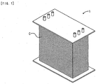
- FIG. 1 shows a perspective view of a polymer electrolyte fuel cell using the adhesive seal member of the present invention.
- a polymer electrolyte fuel cell 1 includes a large number of stacked cells C.
- FIG 2 shows a perspective view of the stacked cells C (three cells are shown).
- FIG 3 shows an exploded perspective view of a single cell C.
- FIG 4 shows a sectional view taken along the line IV-IV in FIG 2 .
- the cell C includes an MEA 2, separators 3, and an adhesive seal member 4a.
- the MEA 2 includes an electrolyte membrane 20 and a pair of electrodes 21a and 21b.
- the electrolyte membrane 20 has a rectangular thin plate shape.
- the pair of electrodes 21 a and 21 b has a rectangular thin plate shape.
- the pair of electrodes 21a and 21 b are disposed on both sides in the stacking direction (vertical direction) interposing the electrolyte membrane 20 therebetween.
- the separator 3 is made of metal and has a rectangular thin plate shape.
- the separator 3 has six grooves in total extending in a longitudinal direction.
- the separator 3 has an uneven cross section due to the grooves (see FIG. 4 ).
- the separators 3 are disposed on the both sides of the MEA 2 in the stacking direction while facing each other.
- gas flow paths 30 are formed by using the uneven shape for supplying gases to the electrodes 21 a and 21 b.
- a refrigerant flow path 31 is formed by using the uneven shape for supplying a refrigerant.
- the adhesive seal member 4a has a rectangular frame shape and has a large wall thickness in the stacking direction.
- the adhesive seal member 4a is bonded to the periphery of the MEA 2 and the separators 3 stacked.
- the adhesive seal member 4a seals the periphery of the MEA 2 between the separators 3 facing each other.
- an adhesive seal member 4b is interposed between the separators 3 of the cells C adjacent to each other in the stacking direction with the back faces of the separators being opposed to each other.
- the adhesive seal member 4b has a rectangular frame shape and has a small wall thickness in the stacking direction.
- the bottom face of the adhesive seal member 4b is bonded to the top face of the separator 3 disposed beneath the adhesive seal member 4b.
- a lip part 40b having a frame shape is formed (in FIG 3 , shown by a hatching pattern in the adhesive seal member 4b that is shown in the upper part of the cell C).
- the lip part 40b is in contact with the bottom face of the separator 3 disposed on the adhesive seal member 4b.
- the lip part 40b is compressed and deformed by clamping force in the stacking direction when the cells C are stacked to assemble the polymer electrolyte fuel cell 1. This forms a seal line, thereby suppressing the leakage of a refrigerant.
- the adhesive seal members 4a and 4b are included in the adhesive seal member of the present invention.
- a fuel gas and an oxidant gas are supplied through the respective gas flow paths 30.
- a refrigerant flows through the flow path 31.
- the periphery of the MEA 2 is sealed with the adhesive seal member 4a.
- the electrolyte membrane 20 is maintained in a wet condition.
- the adhesive seal member 4a can be bonded at a low temperature of about 150°C and for a short period of time. Hence, the electrolyte membrane 20 is unlikely to be deteriorated during the adhesion process.
- the refrigerant is unlikely to be leaked from the refrigerant flow path 31 to the outside.
- the sealing performance of the adhesive seal members 4a and 4b is unlikely to be lowered even at an extremely low temperature of about -20°C to -30°C.
- the adhesive properties of the adhesive seal members 4a and 4b is unlikely to be lowered even in an operating environment of the polymer electrolyte fuel cell 1. Therefore, the polymer electrolyte fuel cell 1 is excellent in durability. In other words, the polymer electrolyte fuel cell 1 can be stably operated over a long period of time.
- a rubber component (A), a softener (E), and a reinforcing agent (F) were kneaded using a Banbury mixer at 120°C for 5 minutes. After cooling the kneaded product, an organic peroxide (B), a crosslinking aid (C), and an adhesive component (D) were added, and the whole was kneaded using an open roll at 50°C for 10 minutes to afford a rubber composition.
- the obtained rubber composition was molded using a press into a flat shape having a predetermined thickness.
- each seal member of Examples 8, 10, 11 and 13 showed a 100% modulus of 2 MPa or more, which was larger than the 100% modulus of the seal member of Comparative Example 1.
- Each seal member of Examples 8, 10, 11 and 13 included the crosslinking aid in a larger amount than that of the seal member of Comparative Example. On this account, each seal member of Examples 8, 10, 11 and 13 obtained a large cross-linking density and a large 100% modulus.
- Table 1 summarizes the peel strength of each test piece in the 90° peel test.
- each seal member of Examples 8, 10, 11 and 13 had the same peel strength as the peel strength of the seal member of Comparative Example 1. As described above, each seal member of Examples 8, 10, 11 and 13 had good adhesive properties.
- each seal member of Comparative Example 1 had a T2 of -31 °C, while each seal member of Examples 8, 10, 11 and 13 had a T2 of -40°C or less. From the result, it is revealed that each seal member of Examples 8, 10, 11 arid 13 is unlikely to be hardened even at an extremely low temperature of -20°C to -30°C and can maintain rubber elasticity.
- Example 13 and Comparative Example 1 each of which contains a paraffinic process oil having a pour point of -15°C alone as the softener showed that the seal member of Example 13 using an EPDM (4) having an ethylene content of 48% by mass had a lower T2 than that of the seal member of Comparative Example 1 using an EPDM (1) having an ethylene content of 54% by mass. From the result, it is ascertained that, when an EPDM having an ethylene content of 40% by mass or more and less than 50% by mass is used, the crystallization at an extremely low temperature is suppressed, and thus the reduction of rubber elasticity can be suppressed.
- Compression set test was carried out on each seal member of Reference Examples, Examples and Comparative Example in accordance with JIS K6262 (2006). Two types of the compression set tests were carried out at -30°C as a low temperature test and at 100°C as a high temperature test. In the low temperature test, a seal member was compressed at -30°C for 24 hours, then released, and maintained at the same temperature for 30 minutes. Then, the thickness was measured and the compression set was calculated. In the high temperature test, a seal member was compressed at 100°C for 24 hours, then released, and maintained at room temperature for 30 minutes. Then, the thickness was measured and the compression set was calculated. In each test, the compression ratio was 25%. The test results are summarized in Table 1.
- each compression set at -30°C and at 100°C is represented by an index where that of the seal member of Comparative Example 1 is regarded as a standard (100).
- the index of compression set was calculated in accordance with Equation (II).
- Compression set index compression set of each seal member / compression set of seal member of Comparative Example 1 ⁇ 100
- each seal member of Examples 8, 10, 11 and 13 had a smaller compression set than the compression set of the seal member of Comparative Example 1.
- a comparison between Example 13 and Comparative Example 1 each of which contains a paraffinic process oil having a pour point of -15°C alone as the softener showed that the seal member of Example 13 using an EPDM (4) having an ethylene content of 48% by mass had a smaller compression set than that of the seal member of Comparative Example 1 using an EPDM (1) having an ethylene content of 54% by mass.
- each seal member of Examples 8, 10, 11 and 13 is unlikely to be flattened both at a high temperature of 100°C and at an extremely low temperature of -30°C. Therefore, with the adhesive seal member of the present invention, the sealing performance at an extremely low temperature can be improved without sacrificing the sealing performance at a high temperature.
- the adhesive seal member of the present invention can be bonded to a member at a low temperature and for a short period of time without using an additional adhesive.
- the adhesive seal member of the present invention does not lose rubber elasticity even at an extremely low temperature of about -20°C to -30°C. Therefore, the adhesive seal member provides good sealing performance even in cold climate areas.
- the adhesive seal member of the present invention enables both adhesion sealing and stress sealing in a wide temperature range in which a fuel cell is used.
Landscapes
- Chemical & Material Sciences (AREA)
- Chemical Kinetics & Catalysis (AREA)
- Sustainable Development (AREA)
- Life Sciences & Earth Sciences (AREA)
- Sustainable Energy (AREA)
- Manufacturing & Machinery (AREA)
- Engineering & Computer Science (AREA)
- Electrochemistry (AREA)
- General Chemical & Material Sciences (AREA)
- Health & Medical Sciences (AREA)
- Medicinal Chemistry (AREA)
- Polymers & Plastics (AREA)
- Organic Chemistry (AREA)
- Fuel Cell (AREA)
Claims (7)
- Haftmitteldichtungselement für eine Brennstoffzelle, wobei das Haftmitteldichtungselement ein Bestandteilselement in der Brennstoffzelle abdichtet und ein vernetztes Produkt einer Kautschukzusammensetzung umfasst, die die Bestandteile (A) bis (D) enthält:(A) mindestens ein Kautschukbestandteil, ausgewählt aus Ethylen-Propylen-Kautschuk und Ethylen-Propylen-Dien-Kautschuk;(B) ein organisches Peroxid mit einer Einstunden-Halbwertszeit-Temperatur von 130°C oder weniger;(C) ein Vernetzungshilfsmittel; und(D) mindestens ein Haftmittelbestandteil, ausgewählt aus einer Resorcin-Verbindung und einer Melamin-Verbindung, einem Aluminat-Haftvermittler und einem Silan-Haftvermittler,dadurch gekennzeichnet, dass der Kautschukbestandteil, ausgewählt aus Ethylen-Propylen-Kautschuk und Ethylen-Propylen-Dien-Kautschuk, einen Ethylen-Anteil von 40 Massen-% oder mehr und weniger als 50 Massen-% aufweist.
- Haftmitteldichtungselement für eine Brennstoffzelle nach Anspruch 1, wobei die Kautschukzusammensetzung weiter (E) einen Weichmacher mit einem Fließpunkt von -40°C oder weniger enthält.
- Haftmitteldichtungselement für eine Brennstoffzelle nach Anspruch 2, wobei (E) der Weichmacher ein Poly-α-olefin ist.
- Haftmitteldichtungselement für eine Brennstoffzelle nach Anspruch 2 oder 3, wobei die Menge von (E) dem Weichmacher 5 Massenteile oder mehr und 50 Massenteile oder weniger, bezogen auf 100 Massenteile des (A) Kautschukbestandteils, beträgt.
- Haftmitteldichtungselement für eine Brennstoffzelle nach einem der Ansprüche 2 bis 4, wobei die Kautschukzusammensetzung weiter einen Weichmacher mit einem Fließpunkt von höher als -40°C enthält.
- Haftmitteldichtungselement für eine Brennstoffzelle nach einem der Ansprüche 1 bis 5, wobei das Haftmitteldichtungselement einen 100%-Modul von 2 MPa oder mehr und 4 MPa oder weniger aufweist.
- Haftmitteldichtungselement für eine Brennstoffzelle nach einem der Ansprüche 1 bis 6, wobei das Haftmitteldichtungselement eine Gehman-Torsionstest-temperatur T2 von -40°C oder weniger aufweist.
Applications Claiming Priority (3)
| Application Number | Priority Date | Filing Date | Title |
|---|---|---|---|
| JP2011092165A JP5719669B2 (ja) | 2011-04-18 | 2011-04-18 | 燃料電池用接着性シール部材 |
| JP2011092159A JP5719668B2 (ja) | 2011-04-18 | 2011-04-18 | 燃料電池用接着性シール部材 |
| PCT/JP2012/060333 WO2012144484A1 (ja) | 2011-04-18 | 2012-04-17 | 燃料電池用接着性シール部材 |
Publications (3)
| Publication Number | Publication Date |
|---|---|
| EP2701224A1 EP2701224A1 (de) | 2014-02-26 |
| EP2701224A4 EP2701224A4 (de) | 2014-09-10 |
| EP2701224B1 true EP2701224B1 (de) | 2016-03-09 |
Family
ID=47041590
Family Applications (1)
| Application Number | Title | Priority Date | Filing Date |
|---|---|---|---|
| EP12774093.4A Active EP2701224B1 (de) | 2011-04-18 | 2012-04-17 | Haftdichtungselement für brennstoffzellen |
Country Status (3)
| Country | Link |
|---|---|
| US (1) | US20130157173A1 (de) |
| EP (1) | EP2701224B1 (de) |
| WO (1) | WO2012144484A1 (de) |
Families Citing this family (5)
| Publication number | Priority date | Publication date | Assignee | Title |
|---|---|---|---|---|
| WO2013147020A1 (ja) * | 2012-03-30 | 2013-10-03 | 東海ゴム工業株式会社 | ゴム組成物および燃料電池シール体 |
| JP5641528B2 (ja) | 2013-03-28 | 2014-12-17 | 住友理工株式会社 | 燃料電池用シール部材およびそれを用いた燃料電池シール体 |
| FR3008428B1 (fr) * | 2013-07-11 | 2015-08-07 | Ceth² | Joint pour pile d'electrolyseur et pile d'electrolyseur equipee d'un tel joint |
| US10680256B2 (en) * | 2016-03-31 | 2020-06-09 | Sumitomo Riko Company Limited | Sealing member for a fuel cell |
| CN110799585A (zh) * | 2017-06-28 | 2020-02-14 | Nok株式会社 | 橡胶组合物及燃料电池隔板用密封材料 |
Family Cites Families (8)
| Publication number | Priority date | Publication date | Assignee | Title |
|---|---|---|---|---|
| US4853428A (en) | 1987-11-02 | 1989-08-01 | Ford Motor Company | Elastomer compositions with superior low temperature flexibility |
| JP3396178B2 (ja) * | 1999-02-10 | 2003-04-14 | 住友ゴム工業株式会社 | 低弾性率ゴム組成物 |
| FI20002884L (fi) * | 2000-10-12 | 2002-04-13 | Duraban Oy | Elastomeerien polyalfaolefiinipehmittimet |
| JP2004150591A (ja) | 2002-10-31 | 2004-05-27 | Nsk Ltd | シール |
| US8487033B2 (en) * | 2007-05-16 | 2013-07-16 | Exxonmobil Chemical Patents Inc. | Thermoplastic elastomer compositions, methods for making the same, and articles made therefrom |
| JP5186317B2 (ja) | 2007-09-21 | 2013-04-17 | 東海ゴム工業株式会社 | 燃料電池用接着性シール部材 |
| JP5219774B2 (ja) | 2008-12-17 | 2013-06-26 | 東海ゴム工業株式会社 | 燃料電池用接着性シール部材 |
| JP5097159B2 (ja) * | 2009-04-01 | 2012-12-12 | 東海ゴム工業株式会社 | 燃料電池モジュールの製造方法、および燃料電池の製造方法 |
-
2012
- 2012-04-17 WO PCT/JP2012/060333 patent/WO2012144484A1/ja not_active Ceased
- 2012-04-17 EP EP12774093.4A patent/EP2701224B1/de active Active
-
2013
- 2013-01-10 US US13/738,095 patent/US20130157173A1/en not_active Abandoned
Also Published As
| Publication number | Publication date |
|---|---|
| WO2012144484A1 (ja) | 2012-10-26 |
| EP2701224A4 (de) | 2014-09-10 |
| EP2701224A1 (de) | 2014-02-26 |
| US20130157173A1 (en) | 2013-06-20 |
Similar Documents
| Publication | Publication Date | Title |
|---|---|---|
| JP5186317B2 (ja) | 燃料電池用接着性シール部材 | |
| JP5396337B2 (ja) | 燃料電池用接着性シール部材 | |
| US8679702B2 (en) | Fuel cell module and manufacturing method thereof | |
| US9437883B2 (en) | Manufacturing method of fuel cell module and manufacturing method of fuel cell | |
| JP5219774B2 (ja) | 燃料電池用接着性シール部材 | |
| US8974982B2 (en) | Fuel cell, fuel cell stack, and method for manufacturing fuel cell | |
| JP6681247B2 (ja) | 燃料電池用シール部材 | |
| EP2833453A1 (de) | Kautschukzusammensetzung und abgedichtete brennstoffzelle | |
| EP2701224B1 (de) | Haftdichtungselement für brennstoffzellen | |
| US9543596B2 (en) | Seal member for fuel cell and fuel cell seal body using same | |
| JP6190607B2 (ja) | 燃料電池シール体 | |
| CN115485139A (zh) | 层叠体 | |
| JP5719669B2 (ja) | 燃料電池用接着性シール部材 | |
| JP6067417B2 (ja) | 積層体の製法 | |
| JP6688718B2 (ja) | 燃料電池用シール部材 | |
| JP6190608B2 (ja) | 燃料電池シール体 | |
| JP5941804B2 (ja) | 積層体およびその製法 | |
| JP5719668B2 (ja) | 燃料電池用接着性シール部材 | |
| US10680256B2 (en) | Sealing member for a fuel cell | |
| JP5268313B2 (ja) | 燃料電池用接着性シール部材 | |
| JP2017183161A (ja) | 燃料電池用シール部材およびその製造方法 | |
| EP3647355A1 (de) | Kautschukzusammensetzung und dichtmittel für brennstoffzellenseparator |
Legal Events
| Date | Code | Title | Description |
|---|---|---|---|
| PUAI | Public reference made under article 153(3) epc to a published international application that has entered the european phase |
Free format text: ORIGINAL CODE: 0009012 |
|
| 17P | Request for examination filed |
Effective date: 20130131 |
|
| AK | Designated contracting states |
Kind code of ref document: A1 Designated state(s): AL AT BE BG CH CY CZ DE DK EE ES FI FR GB GR HR HU IE IS IT LI LT LU LV MC MK MT NL NO PL PT RO RS SE SI SK SM TR |
|
| DAX | Request for extension of the european patent (deleted) | ||
| A4 | Supplementary search report drawn up and despatched |
Effective date: 20140812 |
|
| RIC1 | Information provided on ipc code assigned before grant |
Ipc: H01M 8/10 20060101ALI20140806BHEP Ipc: C08L 21/00 20060101ALI20140806BHEP Ipc: H01M 8/02 20060101AFI20140806BHEP |
|
| RAP1 | Party data changed (applicant data changed or rights of an application transferred) |
Owner name: SUMITOMO RIKO COMPANY LIMITED |
|
| RIC1 | Information provided on ipc code assigned before grant |
Ipc: C08L 23/16 20060101ALI20150504BHEP Ipc: H01M 8/02 20060101AFI20150504BHEP Ipc: H01M 8/10 20060101ALI20150504BHEP Ipc: C08K 5/14 20060101ALN20150504BHEP |
|
| GRAP | Despatch of communication of intention to grant a patent |
Free format text: ORIGINAL CODE: EPIDOSNIGR1 |
|
| INTG | Intention to grant announced |
Effective date: 20150623 |
|
| GRAP | Despatch of communication of intention to grant a patent |
Free format text: ORIGINAL CODE: EPIDOSNIGR1 |
|
| RIC1 | Information provided on ipc code assigned before grant |
Ipc: C08K 5/14 20060101ALN20150731BHEP Ipc: H01M 8/02 20060101AFI20150731BHEP Ipc: H01M 8/10 20060101ALI20150731BHEP Ipc: C08L 23/16 20060101ALI20150731BHEP |
|
| INTG | Intention to grant announced |
Effective date: 20150817 |
|
| GRAS | Grant fee paid |
Free format text: ORIGINAL CODE: EPIDOSNIGR3 |
|
| GRAA | (expected) grant |
Free format text: ORIGINAL CODE: 0009210 |
|
| RIN1 | Information on inventor provided before grant (corrected) |
Inventor name: YAMAMOTO KENJI Inventor name: TANAHASHI HIDEAKI Inventor name: SHIMIZU TAKAYUKI Inventor name: KADONO HIDEYA |
|
| AK | Designated contracting states |
Kind code of ref document: B1 Designated state(s): AL AT BE BG CH CY CZ DE DK EE ES FI FR GB GR HR HU IE IS IT LI LT LU LV MC MK MT NL NO PL PT RO RS SE SI SK SM TR |
|
| REG | Reference to a national code |
Ref country code: GB Ref legal event code: FG4D |
|
| REG | Reference to a national code |
Ref country code: AT Ref legal event code: REF Ref document number: 780093 Country of ref document: AT Kind code of ref document: T Effective date: 20160315 Ref country code: CH Ref legal event code: EP |
|
| REG | Reference to a national code |
Ref country code: FR Ref legal event code: PLFP Year of fee payment: 5 |
|
| REG | Reference to a national code |
Ref country code: IE Ref legal event code: FG4D |
|
| REG | Reference to a national code |
Ref country code: DE Ref legal event code: R096 Ref document number: 602012015426 Country of ref document: DE |
|
| REG | Reference to a national code |
Ref country code: LT Ref legal event code: MG4D |
|
| REG | Reference to a national code |
Ref country code: NL Ref legal event code: MP Effective date: 20160309 |
|
| PG25 | Lapsed in a contracting state [announced via postgrant information from national office to epo] |
Ref country code: HR Free format text: LAPSE BECAUSE OF FAILURE TO SUBMIT A TRANSLATION OF THE DESCRIPTION OR TO PAY THE FEE WITHIN THE PRESCRIBED TIME-LIMIT Effective date: 20160309 Ref country code: FI Free format text: LAPSE BECAUSE OF FAILURE TO SUBMIT A TRANSLATION OF THE DESCRIPTION OR TO PAY THE FEE WITHIN THE PRESCRIBED TIME-LIMIT Effective date: 20160309 Ref country code: ES Free format text: LAPSE BECAUSE OF FAILURE TO SUBMIT A TRANSLATION OF THE DESCRIPTION OR TO PAY THE FEE WITHIN THE PRESCRIBED TIME-LIMIT Effective date: 20160309 Ref country code: NO Free format text: LAPSE BECAUSE OF FAILURE TO SUBMIT A TRANSLATION OF THE DESCRIPTION OR TO PAY THE FEE WITHIN THE PRESCRIBED TIME-LIMIT Effective date: 20160609 Ref country code: GR Free format text: LAPSE BECAUSE OF FAILURE TO SUBMIT A TRANSLATION OF THE DESCRIPTION OR TO PAY THE FEE WITHIN THE PRESCRIBED TIME-LIMIT Effective date: 20160610 |
|
| REG | Reference to a national code |
Ref country code: AT Ref legal event code: MK05 Ref document number: 780093 Country of ref document: AT Kind code of ref document: T Effective date: 20160309 |
|
| PG25 | Lapsed in a contracting state [announced via postgrant information from national office to epo] |
Ref country code: NL Free format text: LAPSE BECAUSE OF FAILURE TO SUBMIT A TRANSLATION OF THE DESCRIPTION OR TO PAY THE FEE WITHIN THE PRESCRIBED TIME-LIMIT Effective date: 20160309 Ref country code: BE Free format text: LAPSE BECAUSE OF NON-PAYMENT OF DUE FEES Effective date: 20160430 Ref country code: RS Free format text: LAPSE BECAUSE OF FAILURE TO SUBMIT A TRANSLATION OF THE DESCRIPTION OR TO PAY THE FEE WITHIN THE PRESCRIBED TIME-LIMIT Effective date: 20160309 Ref country code: LV Free format text: LAPSE BECAUSE OF FAILURE TO SUBMIT A TRANSLATION OF THE DESCRIPTION OR TO PAY THE FEE WITHIN THE PRESCRIBED TIME-LIMIT Effective date: 20160309 Ref country code: LT Free format text: LAPSE BECAUSE OF FAILURE TO SUBMIT A TRANSLATION OF THE DESCRIPTION OR TO PAY THE FEE WITHIN THE PRESCRIBED TIME-LIMIT Effective date: 20160309 Ref country code: SE Free format text: LAPSE BECAUSE OF FAILURE TO SUBMIT A TRANSLATION OF THE DESCRIPTION OR TO PAY THE FEE WITHIN THE PRESCRIBED TIME-LIMIT Effective date: 20160309 Ref country code: PL Free format text: LAPSE BECAUSE OF FAILURE TO SUBMIT A TRANSLATION OF THE DESCRIPTION OR TO PAY THE FEE WITHIN THE PRESCRIBED TIME-LIMIT Effective date: 20160309 |
|
| PG25 | Lapsed in a contracting state [announced via postgrant information from national office to epo] |
Ref country code: EE Free format text: LAPSE BECAUSE OF FAILURE TO SUBMIT A TRANSLATION OF THE DESCRIPTION OR TO PAY THE FEE WITHIN THE PRESCRIBED TIME-LIMIT Effective date: 20160309 Ref country code: IS Free format text: LAPSE BECAUSE OF FAILURE TO SUBMIT A TRANSLATION OF THE DESCRIPTION OR TO PAY THE FEE WITHIN THE PRESCRIBED TIME-LIMIT Effective date: 20160709 |
|
| PG25 | Lapsed in a contracting state [announced via postgrant information from national office to epo] |
Ref country code: CZ Free format text: LAPSE BECAUSE OF FAILURE TO SUBMIT A TRANSLATION OF THE DESCRIPTION OR TO PAY THE FEE WITHIN THE PRESCRIBED TIME-LIMIT Effective date: 20160309 Ref country code: RO Free format text: LAPSE BECAUSE OF FAILURE TO SUBMIT A TRANSLATION OF THE DESCRIPTION OR TO PAY THE FEE WITHIN THE PRESCRIBED TIME-LIMIT Effective date: 20160309 Ref country code: SM Free format text: LAPSE BECAUSE OF FAILURE TO SUBMIT A TRANSLATION OF THE DESCRIPTION OR TO PAY THE FEE WITHIN THE PRESCRIBED TIME-LIMIT Effective date: 20160309 Ref country code: SK Free format text: LAPSE BECAUSE OF FAILURE TO SUBMIT A TRANSLATION OF THE DESCRIPTION OR TO PAY THE FEE WITHIN THE PRESCRIBED TIME-LIMIT Effective date: 20160309 Ref country code: AT Free format text: LAPSE BECAUSE OF FAILURE TO SUBMIT A TRANSLATION OF THE DESCRIPTION OR TO PAY THE FEE WITHIN THE PRESCRIBED TIME-LIMIT Effective date: 20160309 Ref country code: PT Free format text: LAPSE BECAUSE OF FAILURE TO SUBMIT A TRANSLATION OF THE DESCRIPTION OR TO PAY THE FEE WITHIN THE PRESCRIBED TIME-LIMIT Effective date: 20160711 |
|
| REG | Reference to a national code |
Ref country code: CH Ref legal event code: PL |
|
| REG | Reference to a national code |
Ref country code: DE Ref legal event code: R097 Ref document number: 602012015426 Country of ref document: DE |
|
| PG25 | Lapsed in a contracting state [announced via postgrant information from national office to epo] |
Ref country code: IT Free format text: LAPSE BECAUSE OF FAILURE TO SUBMIT A TRANSLATION OF THE DESCRIPTION OR TO PAY THE FEE WITHIN THE PRESCRIBED TIME-LIMIT Effective date: 20160309 Ref country code: BE Free format text: LAPSE BECAUSE OF FAILURE TO SUBMIT A TRANSLATION OF THE DESCRIPTION OR TO PAY THE FEE WITHIN THE PRESCRIBED TIME-LIMIT Effective date: 20160309 |
|
| PLBE | No opposition filed within time limit |
Free format text: ORIGINAL CODE: 0009261 |
|
| STAA | Information on the status of an ep patent application or granted ep patent |
Free format text: STATUS: NO OPPOSITION FILED WITHIN TIME LIMIT |
|
| REG | Reference to a national code |
Ref country code: IE Ref legal event code: MM4A |
|
| PG25 | Lapsed in a contracting state [announced via postgrant information from national office to epo] |
Ref country code: CH Free format text: LAPSE BECAUSE OF NON-PAYMENT OF DUE FEES Effective date: 20160430 Ref country code: LI Free format text: LAPSE BECAUSE OF NON-PAYMENT OF DUE FEES Effective date: 20160430 Ref country code: DK Free format text: LAPSE BECAUSE OF FAILURE TO SUBMIT A TRANSLATION OF THE DESCRIPTION OR TO PAY THE FEE WITHIN THE PRESCRIBED TIME-LIMIT Effective date: 20160309 |
|
| 26N | No opposition filed |
Effective date: 20161212 |
|
| PG25 | Lapsed in a contracting state [announced via postgrant information from national office to epo] |
Ref country code: BG Free format text: LAPSE BECAUSE OF FAILURE TO SUBMIT A TRANSLATION OF THE DESCRIPTION OR TO PAY THE FEE WITHIN THE PRESCRIBED TIME-LIMIT Effective date: 20160609 |
|
| GBPC | Gb: european patent ceased through non-payment of renewal fee |
Effective date: 20160609 |
|
| REG | Reference to a national code |
Ref country code: FR Ref legal event code: PLFP Year of fee payment: 6 |
|
| PG25 | Lapsed in a contracting state [announced via postgrant information from national office to epo] |
Ref country code: IE Free format text: LAPSE BECAUSE OF NON-PAYMENT OF DUE FEES Effective date: 20160417 Ref country code: GB Free format text: LAPSE BECAUSE OF NON-PAYMENT OF DUE FEES Effective date: 20160609 Ref country code: SI Free format text: LAPSE BECAUSE OF FAILURE TO SUBMIT A TRANSLATION OF THE DESCRIPTION OR TO PAY THE FEE WITHIN THE PRESCRIBED TIME-LIMIT Effective date: 20160309 |
|
| REG | Reference to a national code |
Ref country code: FR Ref legal event code: PLFP Year of fee payment: 7 |
|
| PG25 | Lapsed in a contracting state [announced via postgrant information from national office to epo] |
Ref country code: HU Free format text: LAPSE BECAUSE OF FAILURE TO SUBMIT A TRANSLATION OF THE DESCRIPTION OR TO PAY THE FEE WITHIN THE PRESCRIBED TIME-LIMIT; INVALID AB INITIO Effective date: 20120417 Ref country code: CY Free format text: LAPSE BECAUSE OF FAILURE TO SUBMIT A TRANSLATION OF THE DESCRIPTION OR TO PAY THE FEE WITHIN THE PRESCRIBED TIME-LIMIT Effective date: 20160309 |
|
| PG25 | Lapsed in a contracting state [announced via postgrant information from national office to epo] |
Ref country code: LU Free format text: LAPSE BECAUSE OF NON-PAYMENT OF DUE FEES Effective date: 20160417 Ref country code: MC Free format text: LAPSE BECAUSE OF FAILURE TO SUBMIT A TRANSLATION OF THE DESCRIPTION OR TO PAY THE FEE WITHIN THE PRESCRIBED TIME-LIMIT Effective date: 20160309 Ref country code: MK Free format text: LAPSE BECAUSE OF FAILURE TO SUBMIT A TRANSLATION OF THE DESCRIPTION OR TO PAY THE FEE WITHIN THE PRESCRIBED TIME-LIMIT Effective date: 20160309 Ref country code: TR Free format text: LAPSE BECAUSE OF FAILURE TO SUBMIT A TRANSLATION OF THE DESCRIPTION OR TO PAY THE FEE WITHIN THE PRESCRIBED TIME-LIMIT Effective date: 20160309 Ref country code: MT Free format text: LAPSE BECAUSE OF NON-PAYMENT OF DUE FEES Effective date: 20160430 |
|
| PG25 | Lapsed in a contracting state [announced via postgrant information from national office to epo] |
Ref country code: AL Free format text: LAPSE BECAUSE OF FAILURE TO SUBMIT A TRANSLATION OF THE DESCRIPTION OR TO PAY THE FEE WITHIN THE PRESCRIBED TIME-LIMIT Effective date: 20160309 |
|
| PGFP | Annual fee paid to national office [announced via postgrant information from national office to epo] |
Ref country code: FR Payment date: 20240308 Year of fee payment: 13 |
|
| PGFP | Annual fee paid to national office [announced via postgrant information from national office to epo] |
Ref country code: DE Payment date: 20250305 Year of fee payment: 14 |
|
| PG25 | Lapsed in a contracting state [announced via postgrant information from national office to epo] |
Ref country code: FR Free format text: LAPSE BECAUSE OF NON-PAYMENT OF DUE FEES Effective date: 20250430 |