EP2701286A2 - Boîtier pour une machine électrique dotée d'un canal de refroidissement en forme de méandre et de géométries conductrices - Google Patents
Boîtier pour une machine électrique dotée d'un canal de refroidissement en forme de méandre et de géométries conductrices Download PDFInfo
- Publication number
- EP2701286A2 EP2701286A2 EP13175883.1A EP13175883A EP2701286A2 EP 2701286 A2 EP2701286 A2 EP 2701286A2 EP 13175883 A EP13175883 A EP 13175883A EP 2701286 A2 EP2701286 A2 EP 2701286A2
- Authority
- EP
- European Patent Office
- Prior art keywords
- housing
- webs
- longitudinal axis
- cooling channel
- guide
- Prior art date
- Legal status (The legal status is an assumption and is not a legal conclusion. Google has not performed a legal analysis and makes no representation as to the accuracy of the status listed.)
- Granted
Links
Images





Classifications
-
- H—ELECTRICITY
- H02—GENERATION; CONVERSION OR DISTRIBUTION OF ELECTRIC POWER
- H02K—DYNAMO-ELECTRIC MACHINES
- H02K5/00—Casings; Enclosures; Supports
- H02K5/04—Casings or enclosures characterised by the shape, form or construction thereof
- H02K5/20—Casings or enclosures characterised by the shape, form or construction thereof with channels or ducts for flow of cooling medium
- H02K5/203—Casings or enclosures characterised by the shape, form or construction thereof with channels or ducts for flow of cooling medium specially adapted for liquids, e.g. cooling jackets
Definitions
- Electric machines can be cooled by liquids, for example.
- a cooling channel may be provided on the housing of the electric machine, in which a cooling fluid flows, for example in the circumferential direction around the electric machine.
- a cooling surface can be increased.
- the flow velocity of the cooling fluid can be increased.
- the cooling fluid may be helically routed around the housing.
- elements such as cooling fins, cooling needles or the like can be incorporated on the housing.
- such housing are made DE 10141890 A1 known.
- an increase in the flow velocity of the cooling fluid can be achieved by alternately deflecting the cooling fluid in the axial direction.
- dead water areas can arise in which, for example, air bubbles can accumulate and which can reduce the cooling efficiency.
- a housing for a fluid-cooled electric machine has an outer meandering surface and an inner meandering surface which form a closed cooling channel. Furthermore, the housing has at least one first meander web and a second meander web, both of which are arranged on the housing or on the cooling channel such that a cooling fluid is guided in a meandering manner. Furthermore, the housing has at least one guide web, which is arranged between the first and the second meander web.
- the idea of the present invention is based on providing additional guide webs between the meander webs, which lead to a splitting of the flow of the cooling fluid in each case between two adjacent meander webs.
- a reduction of dead water areas is achieved.
- the cooling surface of the housing can be increased and thus the cooling efficiency of the housing with the same hydraulic pumping power can be increased by up to about 30 percent.
- a better ventilation of the cooling channel can be ensured.
- the better venting is effected by the fact that the dead water areas, so the areas that are not achieved by the cooling fluid can be reduced and thus accumulate less air or air bubbles in these dead water areas.
- the guide webs are arranged in the cooling channel such that they do not increase or only slightly increase the flow resistance.
- the guide webs ensure a better mechanical rigidity of the housing and optionally a better mechanical stiffness of the mold in the manufacture of the housing.
- the housing can be used, for example, for fluid cooled electric machines such as generators or motors with a stator and a rotor.
- the housing can be used for electric machines in motor vehicles, in particular in hybrid vehicles.
- the housing has a material with good thermal conductivity.
- the housing may comprise a metal such as aluminum.
- the cooling fluid also referred to as coolant, may be a liquid or a gas.
- the cooling fluid may be water.
- the housing may be cylindrical and suitable for receiving a stator and a rotor.
- the housing has an outer circumferential surface and an inner circumferential surface, which together form a closed cooling channel and are preferably made in one piece, that is to say integrally or cohesively.
- the guide webs and possibly also the meander webs can be connected both to the inner circumferential surface and to the outer lateral surface.
- the cooling channel can be designed in two or more parts in the axial direction.
- the inner shell surface and the outer shell surface may be separately, i. be made in two pieces in the radial direction.
- the guide webs and possibly also the meander webs on the inner circumferential surface can be bonded cohesively.
- the outer and the inner circumferential surface of the cooling channel can be designed cylindrically with different diameters.
- the cooling channel can also be referred to as a cooling jacket.
- the housing further has at least one first meander land and at least one second meander land.
- the housing a plurality of first and a plurality of second meandering webs.
- a meandering web can be an elongate element with a longitudinal axis which is directly connected to the edge of the cooling channel.
- the first meander web is directly connected to the edge of a first side of the housing and the second meander web to the edge on the other side of the housing.
- the meandering webs can alternate in the direction of rotation.
- the meander webs can be made in one piece or integrally or cohesively with the lateral surfaces.
- the meandering webs may be alternately arranged on a first and a second edge of the cooling channel and project into the cooling channel. If a longitudinal axis of the housing is arranged, for example, perpendicular to a horizontal, then a first edge of the cooling channel can be arranged at the top and a second edge of the cooling channel at the bottom. For example, a plurality of first meander webs may begin at the first edge of the cooling channel and extend downwardly parallel to the longitudinal axis of the housing. The first meander webs are arranged at a distance from the second edge. The second meander webs can start at the second edge, that is to say at the bottom edge of the cooling channel and run upwards parallel to the longitudinal axis of the housing.
- the first and second meander webs are arranged on the cooling channel such that the cooling fluid is guided meander-shaped in the cooling channel.
- the cooling fluid can be guided by the meander webs alternately at least in sections substantially parallel and antiparallel to the longitudinal axis of the housing.
- Antiparallel means that the flow direction of the cooling fluid is substantially parallel to the longitudinal axis, but in the opposite direction than before. That is, the cooling fluid can be alternately deflected in the axial direction of the housing.
- At least one guide web is provided between the at least one first and the at least one second meander web.
- the guide bar also referred to as a gutter, can be arranged on the housing such that a cooling surface of the housing is increased. The cooling surface is thereby increased, that causes the leadership of the cooling fluid through the guide bar a reduction of dead water areas. That is, with the guide bar is more area achieved by the cooling fluid than without a guide bar.
- the guide bar can be an elongate component with a longitudinal axis. The guide bar is not connected to any of the edges of the cooling channel.
- a guide bar can be provided between each first and second meander web.
- the cooling fluid flows essentially in the circumferential direction and is meandered alternately in the axial direction by the meander webs.
- the cooling fluid can flow around the guide webs on all sides and is thereby divided between two adjacent meander webs into two separate flows, e.g. better to reach corners of the cooling channel.
- the guide bar is designed to divide the cooling fluid into two parallel flows or streams. In this case, both flows are performed parallel or anti-parallel to the longitudinal axis of the housing between the first and the second meandering web.
- the guide web causes a splitting of the flow of the cooling fluid between two adjacent meander webs, so that the cooling fluid flows on both sides of the guide web essentially in the same direction at least in sections and is subsequently brought together again.
- the guide bar is cohesively connected to the outer and the inner circumferential surface. That is, the guide bar is integral or integral with the housing or with the lateral surfaces of the housing.
- the housing for example by means of the lost foam method, which for example DE 102008040873 A1 is known to be produced.
- both the guide bar and the lateral surfaces and possibly also the meander bars form a unit.
- the guide bar can be connected by welding or soldering with the inner and with the outer circumferential surface.
- the first and the second meandering web or the plurality of first and second meandering webs can be made cohesively with the outer and the inner circumferential surface.
- the guide bar may be executed in a multi-part design of the housing, cohesively with one of the lateral surfaces and flush with the abut other lateral surface. Furthermore, in the case of a two-part or multi-part design of the cooling channel, a gap can be provided between the guide web and one of the lateral surfaces.
- a longitudinal axis of the guide web runs essentially parallel to the longitudinal axis of the housing. That is, the guide webs or the longitudinal axes of the guide webs can be oriented axially, that is parallel to the longitudinal axis of the housing. Alternatively or additionally, a longitudinal axis of the first meandering web and a longitudinal axis of the second meandering web are oriented parallel to the longitudinal axis of the housing. For example, both the longitudinal axes of all guide webs and the longitudinal axes of all meander webs may extend parallel to the longitudinal axis of the housing. As a result, an uncomplicated structure of the housing is provided.
- the guide bar or all guide webs may be arranged centrally between each adjacent first and second meandering webs. In this way, a particularly advantageous division of the cooling fluid between the first and the second meander web can be effected, so that as much surface of the housing is achieved by the cooling fluid.
- the longitudinal axis of the guide bar forms an angle with the longitudinal axis of the housing. That is, the longitudinal axis of the guide bar may be set at an angle with respect to an axial direction of the housing. Different guide ribs on the housing can have different angles of inclination.
- the longitudinal axis of a guide bar relative to the longitudinal axis of the housing may be inclined by approximately 30 °.
- a longitudinal axis of another guide bar can be tilted by -30 ° relative to a longitudinal axis of the housing. This means that two guide webs, for example, are arranged mirror-symmetrically to a first meander web and / or a second meander web.
- it can be tilt angle of the guide webs between 0 ° and 30 ° or between 0 ° and -30 °.
- a symmetrical arrangement of the guide webs may be advantageous, since this ensures a direction independent of the flow through the cooling channel.
- the guide webs may be arranged asymmetrically.
- the guide webs can be arranged asymmetrically with respect to the meander webs. That the guide webs may e.g. not centrally located between the right and left Gurandersteg. Additionally or alternatively, the guide webs may be arranged asymmetrically with respect to an axial direction.
- the individual meander loops i. a sequence of guide bar and meander bar be designed differently or asymmetrically. This can simplify the manufacturing process, e.g. For manufacturing reasons, certain webs are possible in one place on the circumference, but not on another, e.g. because of the Entformraum.
- a cross-section of the guide web which is perpendicular to the longitudinal axis of the guide web, varies along the longitudinal axis of the housing. That is, the cross section of the guide bar may change in the axial direction of the housing.
- a guide bar may taper to a direction of the longitudinal axis of the housing and be wider towards the other direction.
- a guide bar can be designed rod-shaped, diamond-shaped or triangular.
- At least one further guide web is provided between the first and the second meander web. That is, between two adjacent meander webs at least two guide webs are arranged. In this case, a distance between the guide webs in each case correspond to the distance of a guide bar to the next meander bar.
- the guide webs between the first and the second meandering web can be arranged parallel to one another. Furthermore, these guide webs may have different lengths and shapes. Furthermore, the guide webs can be arranged at different distances from the first and the second edge of the cooling channel.
- At least two guide webs are connected to one another by deflection webs.
- the deflecting webs can serve as deflection aids.
- the deflection webs can be linear or straight, for example.
- the deflection webs for example, perpendicular to axial direction of the cooling channel.
- the deflecting webs can be rounded or arcuate.
- interruptions are provided in the guide webs and / or in the meander webs.
- the breaks can be e.g. Be openings in which the inner and outer lateral surface are not connected.
- the cooling surface can be increased.
- the interruptions allow an exchange between the individual channels through which the cooling fluid flows.
- the interruptions may be particularly advantageous if the guide webs are connected by means of deflection webs, so that pronounced parallel paths of the cooling liquid arise in the cooling channel.
- the interruptions can produce a pressure equalization between the paths.
- a fluid-cooled electric machine in this case has a stator, a rotor and a housing described above.
- the stator and the rotor are arranged in the housing.
- the housing is designed to cool the stator and / or the rotor by means of a cooling fluid.
- a method of manufacturing a housing as described above comprises the following steps: providing an outer and an inner circumferential surface, which together form a closed cooling channel. Providing at least a first and a second meandering ridge on the housing such that a cooling fluid is alternately guided in parallel and anti-parallel to a longitudinal axis of the housing. Providing a guide bar between the first and the second meandering bar such that the guide bar connects the outer and the inner circumferential surface and increases a cooling surface of the housing.
- a lost-foam method, a welding method or a soldering method can be used for the integral production of the housing.
- the cooling channel is made in one piece.
- the outer circumferential surface and the inner circumferential surface are connected by the guide webs and possibly also by the meander webs materially connected radially. That is, the Leitstege are both with the inner as well as with the outer surface cohesively connected.
- the cooling channel can be produced using a sand casting method, in particular a lost foam method.
- the cooling channel is designed in two parts in the axial direction and in the radial direction.
- the outer circumferential surface and the inner circumferential surface can be materially connected by the guide webs as described above.
- the guide webs and the meander webs can be materially bonded to one of the lateral surfaces.
- the guide webs and the meander webs can be made in one piece with the inner circumferential surface.
- a gap between the outer circumferential surface and the guide webs may be present in the cooling channel.
- the individual parts of the cooling channel may be e.g. Milled, poured and welded.
- the inner circumferential surface can be produced together with the guide webs and the meander webs by a die-casting method and by radial demoulding.
- cooling channel 9 In the figures, only parts of a cooling channel 9 are partially shown. The entire cooling channel 9 can have several, in particular a plurality of meandering turns.
- Fig. 1 the course of flow velocities in the cooling channel 9 of a known housing is shown.
- the cooling channel is a single meander executed.
- the first meander webs 11 are arranged, for example, on a first edge 23 of the cooling channel, and the second meander webs 13 are arranged on a second edge 25 of the cooling channel.
- a cooling fluid flows substantially in the circumferential direction 31 around an in Fig. 1 not shown electric machine.
- the cooling fluid is deflected several times in the axial direction 33. This dead water areas can arise, which are not achieved by the cooling fluid and thus reduce cooling efficiency. Furthermore, air bubbles can accumulate in the dead water areas, which can lead to ventilation problems.
- FIG. 2 an embodiment of the invention is shown in which in the cooling channel 9 of a housing 1 guide webs 17 between the meandering webs 11, 13 are introduced.
- Fig. 2 shows a course of flow velocities of the cooling fluid in the cooling channel 9 in the projection in a plane.
- the cooling efficiency at the same hydraulic pump power for example, be increased by about 30%.
- the increase of the cooling efficiency is due to an enlargement of the cooling surface and the guidance of the flow of the cooling fluid for the reduction of dead water areas.
- the venting of the cooling channel 9 is improved, since now less air or air bubbles can accumulate in the dead water areas.
- the guide webs 17 provided in the cooling channel 9 promote the rigidity of the housing 1, which, for example, in FIG Fig. 9 is shown.
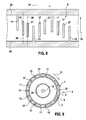
- Fig. 9 shows a cross section of an electric machine 3 with a stator 27 and a rotor 29, which are surrounded by a housing 1.
- the housing has an outer lateral surface 5 and an inner lateral surface 7, which together form a closed cooling channel 9.
- On the housing or on the cooling channel 9 a plurality of first meandering webs 11 and a plurality of second meandering webs 13 is provided.
- a longitudinal axis 15 of the housing 1 is oriented perpendicular to the image plane.
- the first and second meandering webs 11, 13 run as in Fig.
- the meander webs 11, 13 are arranged on the housing 1 in such a way that the cooling fluid is alternately guided parallel and antiparallel to the longitudinal axis 15 of the housing 1. Further, in each case between a first meandering web 11 and a second meandering web 13, a guide web 17 is provided in each case.
- the guide webs 17 connect the outer lateral surface 5 with the inner circumferential surface 7.
- the width of the cooling channel 9 can in the embodiment in Fig. 9 for example, be between 3 and 6 mm. Accordingly, the width of the first meander webs 11, second meander webs 13 and the guide webs 17 can be between 3 and 6 mm.
- the axially projected length of the guide ribs 17 is less than the axial dimension of the cooling channel 9. That is, the guide ribs 17 are connected to neither the first edge 23 nor the second edge 25 of the cooling channel 9. In this way, the cooling fluid can flow past on both sides of the guide bar 17.
- the guide webs 17 can be produced in a casting process, for example in the lost-foam process, and in this way can be materially bonded to the housing.
- a meandering cooling channel 9 with three shaping disks, also referred to as a slice can be produced.
- the introduction of guide webs 17 in the cooling channel 9 or in the housing 1 requires no additional slices. In this way, the manufacturing cost of the housing 1 can be kept low.
- the guide webs 17 or a longitudinal axis 39 of the guide webs 17 are oriented parallel to the first meander webs 11, to the second meander webs 13 and to the axial direction 33 and to the longitudinal axis 15 of the housing 1.
- the guide webs 17 and the longitudinal axis 39 of the guide webs 17 relative to the axial direction 33 may be employed at an angle 19.
- the guide webs 17 close an angle 19 with the projection of the longitudinal axis 15 on the cooling channel 9 a.
- the guide webs 17 may include different angles with the longitudinal axis 15.
- adjacent guide ribs 17 are each arranged mirror-symmetrically to the meander web 11 or the second meander web 13 arranged therebetween.
- a guide bar 17 may enclose an angle of approximately 30 ° with the longitudinal axis 15 of the housing 1.
- One adjacent guide bar 17 may include an angle of -30 ° with the longitudinal axis 15.
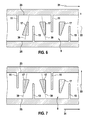
- guide webs 17 may have a variable in the axial direction 33 cross-section. As in 6 and 7 shown, the cross section of the guide ribs 17 changes in the axial direction. In this case, the cross section can vary differently with different guide webs 17.
- the guide bar 17 tapers towards the second edge 25 of the cooling channel.
- the shape of the guide webs 17 corresponds for example to a triangle.
- adjacent guide webs 17 are mirror-symmetrical with respect to the intermediate meander webs 11, 13 executed.
- the guide webs 17 each taper alternately toward the first edge 23 and the second edge 25 of the cooling channel 9.
- a plurality, in particular two guide webs 17 between each two adjacent meandering webs 11 and 13 may be arranged.
- a further guide bar 21 located next to the guide bar 17, a further guide bar 21.
- the guide webs 17, 21 may be offset relative to an axial direction 33 may be arranged. That is, for example, the guide bar 17 is arranged closer to the first edge 23 of the cooling channel 9, while the further guide bar 21 is arranged closer to the second edge 25 of the cooling channel 9.
- Fig. 3 is a plastic representation of the cooling channel 9 of the housing 1 is shown. Only the volume of fluid which can be filled by the cooling fluid is shown.
- the cooling channel may include a cooling fluid supply 35 and a cooling fluid discharge 37. These can be provided as lines in the housing 1.
- Fig. 4 is the flow pattern of an example in Fig. 2 and Fig. 3 shown cooling channels 9 illustrated with arrows. It can be seen that the cooling fluid can flow past the guide bar 17 on four sides.
- the guide bar 17 divides the flow of cooling fluid between two meandering webs 11, 13 into two separate streams, which can then be brought together again. In the illustrated embodiment, the cooling fluid can flow past right and left on the guide bar 17.
- a cooling channel 9 is shown, in which by way of example a guide web 17 is shown with an asymmetrical shape.
- the guide bar 17 in the upper part of a triangular plan and is executed in the lower area linear.
- the remaining guide webs 17 may have a different or different shape.
- a cooling channel 9 is shown with deflecting webs 41.
- the deflecting webs 41 each connect two adjacent guide webs 17 with one another, so that the cooling fluid path separated by the individual guide webs 17 is lengthened in this way.
- the deflection webs 41 are in Fig. 11 executed in a straight line.
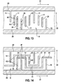
- Fig. 12 is a cooling channel 9 with interruptions 43 to guide webs 17, 21 and shown on meandering webs 13.
- the interruptions 43 may be provided on all guide webs 17, 21 and on all meandering webs 11, 13 or only on selected webs 11, 13, 17, 21.
- the interruptions 43 increase the cooling surface and allow a pressure equalization within the cooling channel 9.
- Fig. 14 is a cooling channel 9 shown, in which both deflecting webs 41 and 43 interruptions are provided in the guide webs 17, 21 combined.
- two guide webs 17, 21 between two adjacent meandering webs 11, 13 are arranged.
- the cooling channel 9 can be as in relation to Fig. 9 already described in one piece. That is, the guide webs 17 and the meander webs 11, 13 are each materially connected both with the inner circumferential surface 7 and with the outer circumferential surface 5. Alternatively, the cooling channel 9 can be designed in several parts. In Fig. 15 the design of the inner circumferential surface 7 is shown at radially two-part design of the cooling channel 9. In this case, the guide webs 17 and the meander webs 11, 13 are integrally connected to the inner circumferential surface 7. In the Fig. 15 not shown outer surface 5 is made separately. In this case, with a composite cooling channel 9, a gap between the guide webs 17 and the outer circumferential surface 5 remain.
Landscapes
- Engineering & Computer Science (AREA)
- Power Engineering (AREA)
- Motor Or Generator Frames (AREA)
- Motor Or Generator Cooling System (AREA)
Applications Claiming Priority (1)
| Application Number | Priority Date | Filing Date | Title |
|---|---|---|---|
| DE102012215018.8A DE102012215018A1 (de) | 2012-08-23 | 2012-08-23 | Gehäuse für eine elektrische Maschine mit mäanderförmigem Kühlkanal und Leitgeometrien |
Publications (3)
| Publication Number | Publication Date |
|---|---|
| EP2701286A2 true EP2701286A2 (fr) | 2014-02-26 |
| EP2701286A3 EP2701286A3 (fr) | 2018-03-28 |
| EP2701286B1 EP2701286B1 (fr) | 2020-03-04 |
Family
ID=48782974
Family Applications (1)
| Application Number | Title | Priority Date | Filing Date |
|---|---|---|---|
| EP13175883.1A Active EP2701286B1 (fr) | 2012-08-23 | 2013-07-10 | Boîtier pour une machine électrique dotée d'un canal de refroidissement en forme de méandre et de géométries conductrices |
Country Status (2)
| Country | Link |
|---|---|
| EP (1) | EP2701286B1 (fr) |
| DE (1) | DE102012215018A1 (fr) |
Cited By (11)
| Publication number | Priority date | Publication date | Assignee | Title |
|---|---|---|---|---|
| CN105743268A (zh) * | 2016-03-01 | 2016-07-06 | 哈尔滨理工大学 | 一种按损耗比率分配内外冷却介质流量的通风结构及方法 |
| WO2016062440A3 (fr) * | 2014-10-23 | 2016-07-21 | Robert Bosch Gmbh | Carter refroidi par fluide pour machine électrique |
| DE102016210302A1 (de) * | 2016-06-10 | 2017-12-14 | Volkswagen Aktiengesellschaft | Kühlstruktur in einem Gehäuse oder Werkzeug |
| EP3673566A1 (fr) * | 2017-08-24 | 2020-07-01 | IFP Energies nouvelles | Machine electrique avec dispositif de refroidissement comprenant un canal partiellement subdivise |
| CN112134414A (zh) * | 2019-06-24 | 2020-12-25 | 法雷奥西门子新能源汽车(德国)有限公司 | 用于电机的定子壳体、电机和车辆 |
| US20210401247A1 (en) * | 2020-06-29 | 2021-12-30 | Makita Corporation | Cleaner |
| EP4030595A1 (fr) * | 2021-01-18 | 2022-07-20 | Flender GmbH | Machine dynamoélectrique à refroidissement du système de bague collectrice |
| US11777365B1 (en) * | 2022-05-23 | 2023-10-03 | Nanchang Sanrui Intelligent Technology Co., Ltd | Motor with flexible variable flow channel |
| CN117254629A (zh) * | 2023-11-15 | 2023-12-19 | 广东启新汽车零部件有限公司 | 一种汽车电机外壳 |
| CN119369166A (zh) * | 2024-11-21 | 2025-01-28 | 珠海格力智能装备有限公司 | 床身冷却结构及机床 |
| WO2025228758A1 (fr) * | 2024-05-03 | 2025-11-06 | Robert Bosch Gmbh | Boîtier pour une transmission, par exemple d'un dispositif d'entraînement électrique pour un véhicule |
Families Citing this family (9)
| Publication number | Priority date | Publication date | Assignee | Title |
|---|---|---|---|---|
| DE102014204816A1 (de) * | 2014-03-14 | 2015-09-17 | Zf Friedrichshafen Ag | Elektrische Maschine mit einem Kühlelement |
| DE102016207232A1 (de) * | 2016-04-28 | 2017-11-02 | Magna powertrain gmbh & co kg | Elektrische Maschine |
| JP7088033B2 (ja) | 2019-01-08 | 2022-06-21 | 株式会社デンソー | 回転電機 |
| DE102020206000A1 (de) | 2019-10-10 | 2021-04-15 | Robert Bosch Gesellschaft mit beschränkter Haftung | Elektrische Maschine mit Bypass-Kühlkanal |
| DE102020208488A1 (de) | 2020-07-07 | 2022-01-13 | Zf Friedrichshafen Ag | Fluidkühlanordnung und elektrische Maschine mit einer Fluidkühlanordnung |
| DE102021201804A1 (de) | 2021-02-25 | 2022-08-25 | Volkswagen Aktiengesellschaft | Gehäuse für eine elektrische Maschine mit einem sich selbst entlüftenden Kühlmantel |
| JP7841406B2 (ja) * | 2022-11-11 | 2026-04-07 | トヨタ自動車株式会社 | 電気モータ |
| US20250125164A1 (en) * | 2023-10-16 | 2025-04-17 | Applied Materials, Inc. | Heat transfer jackets and sensor assemblies, and related methods and processing chambers, for semiconductor manufacturing |
| JP2025139114A (ja) * | 2024-03-12 | 2025-09-26 | トヨタ自動車株式会社 | 冷却構造 |
Citations (2)
| Publication number | Priority date | Publication date | Assignee | Title |
|---|---|---|---|---|
| DE10141890A1 (de) | 2001-08-28 | 2003-03-20 | Bosch Gmbh Robert | Elektrische Maschine |
| DE102008040873A1 (de) | 2008-07-30 | 2010-02-04 | Robert Bosch Gmbh | Verfahren zur Herstellung einer elektrischen Maschine sowie Elektrische Maschine für ein Hybridfahrzeug |
Family Cites Families (3)
| Publication number | Priority date | Publication date | Assignee | Title |
|---|---|---|---|---|
| DE202004018968U1 (de) * | 2004-12-08 | 2005-02-10 | Bbt Thermotechnik Gmbh | Wärmetauscher |
| DE102009001387A1 (de) * | 2009-03-06 | 2010-09-09 | Robert Bosch Gmbh | Elektromaschine |
| AT510749B1 (de) * | 2010-11-18 | 2012-09-15 | Avl List Gmbh | Kreiskolbenbrennkraftmaschine |
-
2012
- 2012-08-23 DE DE102012215018.8A patent/DE102012215018A1/de not_active Withdrawn
-
2013
- 2013-07-10 EP EP13175883.1A patent/EP2701286B1/fr active Active
Patent Citations (2)
| Publication number | Priority date | Publication date | Assignee | Title |
|---|---|---|---|---|
| DE10141890A1 (de) | 2001-08-28 | 2003-03-20 | Bosch Gmbh Robert | Elektrische Maschine |
| DE102008040873A1 (de) | 2008-07-30 | 2010-02-04 | Robert Bosch Gmbh | Verfahren zur Herstellung einer elektrischen Maschine sowie Elektrische Maschine für ein Hybridfahrzeug |
Cited By (20)
| Publication number | Priority date | Publication date | Assignee | Title |
|---|---|---|---|---|
| WO2016062440A3 (fr) * | 2014-10-23 | 2016-07-21 | Robert Bosch Gmbh | Carter refroidi par fluide pour machine électrique |
| US10680497B2 (en) | 2014-10-23 | 2020-06-09 | Robert Bosch Gmbh | Fluid-cooled housing for an electrical machine |
| CN105743268B (zh) * | 2016-03-01 | 2018-05-29 | 哈尔滨理工大学 | 一种按损耗比率分配内外冷却介质流量的通风结构及方法 |
| CN105743268A (zh) * | 2016-03-01 | 2016-07-06 | 哈尔滨理工大学 | 一种按损耗比率分配内外冷却介质流量的通风结构及方法 |
| DE102016210302A1 (de) * | 2016-06-10 | 2017-12-14 | Volkswagen Aktiengesellschaft | Kühlstruktur in einem Gehäuse oder Werkzeug |
| EP3673566A1 (fr) * | 2017-08-24 | 2020-07-01 | IFP Energies nouvelles | Machine electrique avec dispositif de refroidissement comprenant un canal partiellement subdivise |
| US11515744B2 (en) * | 2019-06-24 | 2022-11-29 | Valeo Siemens Eautomotive Germany Gmbh | Stator housing for an electric machine, electric machine, and vehicle |
| CN112134414A (zh) * | 2019-06-24 | 2020-12-25 | 法雷奥西门子新能源汽车(德国)有限公司 | 用于电机的定子壳体、电机和车辆 |
| EP3758197A1 (fr) * | 2019-06-24 | 2020-12-30 | Valeo Siemens eAutomotive Germany GmbH | Boîtier de stator pour une machine électrique, machine électrique et véhicule |
| JP2021002997A (ja) * | 2019-06-24 | 2021-01-07 | ヴァレオ ジーメンス エーアオトモーティヴェ ゲルマニー ゲーエムベーハーValeo Siemens eAutomotive Germany GmbH | 電気機械用のステータハウジング、電気機械、及び車両 |
| US20210401247A1 (en) * | 2020-06-29 | 2021-12-30 | Makita Corporation | Cleaner |
| US11744419B2 (en) * | 2020-06-29 | 2023-09-05 | Makita Corporation | Cleaner |
| EP4030595A1 (fr) * | 2021-01-18 | 2022-07-20 | Flender GmbH | Machine dynamoélectrique à refroidissement du système de bague collectrice |
| WO2022152685A1 (fr) * | 2021-01-18 | 2022-07-21 | Flender Gmbh | Machine dynamo-électrique avec refroidissement du système à bagues collectrices |
| US12244189B2 (en) | 2021-01-18 | 2025-03-04 | Flender Gmbh | Dynamoelectric machine having cooling of the slip ring system |
| US11777365B1 (en) * | 2022-05-23 | 2023-10-03 | Nanchang Sanrui Intelligent Technology Co., Ltd | Motor with flexible variable flow channel |
| CN117254629A (zh) * | 2023-11-15 | 2023-12-19 | 广东启新汽车零部件有限公司 | 一种汽车电机外壳 |
| CN117254629B (zh) * | 2023-11-15 | 2024-02-06 | 广东启新汽车零部件有限公司 | 一种汽车电机外壳 |
| WO2025228758A1 (fr) * | 2024-05-03 | 2025-11-06 | Robert Bosch Gmbh | Boîtier pour une transmission, par exemple d'un dispositif d'entraînement électrique pour un véhicule |
| CN119369166A (zh) * | 2024-11-21 | 2025-01-28 | 珠海格力智能装备有限公司 | 床身冷却结构及机床 |
Also Published As
| Publication number | Publication date |
|---|---|
| DE102012215018A1 (de) | 2014-02-27 |
| EP2701286B1 (fr) | 2020-03-04 |
| EP2701286A3 (fr) | 2018-03-28 |
Similar Documents
| Publication | Publication Date | Title |
|---|---|---|
| EP2701286B1 (fr) | Boîtier pour une machine électrique dotée d'un canal de refroidissement en forme de méandre et de géométries conductrices | |
| EP2688183B1 (fr) | Bobine électrique fabriquée selon une technique de coulage | |
| EP2851118B1 (fr) | Dispositif de mélange et d'échange thermique et procédé pour sa fabrication | |
| DE2522106C3 (de) | Vorrichtung zum kontinuierlichen Mischen fließfähiger Stoffe und Verfahren zum Herstellen eines Mischeinsatzes | |
| EP2834906B1 (fr) | Moteur électrique | |
| DE102016216019A1 (de) | Einsatz für einen Kühlmantel einer elektrischen Maschine | |
| DE102013222697A1 (de) | Elektrische Maschine mit in ein Gehäuse integriertem Kühlkanal | |
| WO2012066069A2 (fr) | Moteur électrique | |
| WO2018114099A1 (fr) | Enveloppe à chemise de refroidissement, en particulier pour une machine électrique | |
| DE10018642A1 (de) | Drehelektromaschine | |
| DE102023102021A1 (de) | Verfahren zur Herstellung eines Stators und Stator | |
| EP4331095B1 (fr) | Machine électrique | |
| DE102012221886A1 (de) | Kühlstruktur für eine elektrische Maschine | |
| EP1815925B1 (fr) | Procédé et dispositif pour la coulée continue des blooms profilés à double T | |
| DE10319230A1 (de) | Kolben mit Kühlkanal mit verbesserter Durchsatzleistung | |
| DE102005030797A1 (de) | Käfigläufer einer Induktionsmaschine | |
| EP3883099B1 (fr) | Unité de refroidissement pour une machine électrique et procédé de fabrication d'une unité de refroidissement | |
| DE102015202004A1 (de) | Käfigläuferrotor mit stabilem Kurzschlussring für eine elektrische Asynchronmaschine sowie Verfahren zum Fertigen desselben | |
| DE102021123317A1 (de) | Gehäuse mit mäanderförmigem Kühlmittelkanal für eine elektrische Maschine | |
| DE102007032973B4 (de) | Y-förmige Kühlrippenanordnung | |
| DE102023211439B3 (de) | Gehäuse für einen Stator einer elektrischen Maschine | |
| EP1795281A2 (fr) | Lingotière | |
| EP3700697B1 (fr) | Procédé pour la fabrication de pièces coulées pourvues de microcanaux | |
| DE102023103204A1 (de) | Verfahren zum Herstellen eines Läufers und/oder Rotors sowie Läufer und/oder Rotor und elektrische Maschine | |
| EP3582370A1 (fr) | Corps en couches, machine électrique ou stator ainsi que procédé de fabrication d'un corps en couches |
Legal Events
| Date | Code | Title | Description |
|---|---|---|---|
| PUAI | Public reference made under article 153(3) epc to a published international application that has entered the european phase |
Free format text: ORIGINAL CODE: 0009012 |
|
| AK | Designated contracting states |
Kind code of ref document: A2 Designated state(s): AL AT BE BG CH CY CZ DE DK EE ES FI FR GB GR HR HU IE IS IT LI LT LU LV MC MK MT NL NO PL PT RO RS SE SI SK SM TR |
|
| AX | Request for extension of the european patent |
Extension state: BA ME |
|
| PUAL | Search report despatched |
Free format text: ORIGINAL CODE: 0009013 |
|
| AK | Designated contracting states |
Kind code of ref document: A3 Designated state(s): AL AT BE BG CH CY CZ DE DK EE ES FI FR GB GR HR HU IE IS IT LI LT LU LV MC MK MT NL NO PL PT RO RS SE SI SK SM TR |
|
| AX | Request for extension of the european patent |
Extension state: BA ME |
|
| RIC1 | Information provided on ipc code assigned before grant |
Ipc: H02K 5/20 20060101AFI20180221BHEP |
|
| STAA | Information on the status of an ep patent application or granted ep patent |
Free format text: STATUS: REQUEST FOR EXAMINATION WAS MADE |
|
| 17P | Request for examination filed |
Effective date: 20180928 |
|
| RBV | Designated contracting states (corrected) |
Designated state(s): AL AT BE BG CH CY CZ DE DK EE ES FI FR GB GR HR HU IE IS IT LI LT LU LV MC MK MT NL NO PL PT RO RS SE SI SK SM TR |
|
| STAA | Information on the status of an ep patent application or granted ep patent |
Free format text: STATUS: EXAMINATION IS IN PROGRESS |
|
| 17Q | First examination report despatched |
Effective date: 20190418 |
|
| GRAP | Despatch of communication of intention to grant a patent |
Free format text: ORIGINAL CODE: EPIDOSNIGR1 |
|
| STAA | Information on the status of an ep patent application or granted ep patent |
Free format text: STATUS: GRANT OF PATENT IS INTENDED |
|
| INTG | Intention to grant announced |
Effective date: 20191203 |
|
| GRAS | Grant fee paid |
Free format text: ORIGINAL CODE: EPIDOSNIGR3 |
|
| GRAA | (expected) grant |
Free format text: ORIGINAL CODE: 0009210 |
|
| STAA | Information on the status of an ep patent application or granted ep patent |
Free format text: STATUS: THE PATENT HAS BEEN GRANTED |
|
| AK | Designated contracting states |
Kind code of ref document: B1 Designated state(s): AL AT BE BG CH CY CZ DE DK EE ES FI FR GB GR HR HU IE IS IT LI LT LU LV MC MK MT NL NO PL PT RO RS SE SI SK SM TR |
|
| REG | Reference to a national code |
Ref country code: GB Ref legal event code: FG4D Free format text: NOT ENGLISH |
|
| REG | Reference to a national code |
Ref country code: CH Ref legal event code: EP |
|
| REG | Reference to a national code |
Ref country code: AT Ref legal event code: REF Ref document number: 1241507 Country of ref document: AT Kind code of ref document: T Effective date: 20200315 |
|
| REG | Reference to a national code |
Ref country code: DE Ref legal event code: R096 Ref document number: 502013014372 Country of ref document: DE |
|
| REG | Reference to a national code |
Ref country code: IE Ref legal event code: FG4D Free format text: LANGUAGE OF EP DOCUMENT: GERMAN |
|
| RAP2 | Party data changed (patent owner data changed or rights of a patent transferred) |
Owner name: ROBERT BOSCH GMBH |
|
| PG25 | Lapsed in a contracting state [announced via postgrant information from national office to epo] |
Ref country code: NO Free format text: LAPSE BECAUSE OF FAILURE TO SUBMIT A TRANSLATION OF THE DESCRIPTION OR TO PAY THE FEE WITHIN THE PRESCRIBED TIME-LIMIT Effective date: 20200604 Ref country code: FI Free format text: LAPSE BECAUSE OF FAILURE TO SUBMIT A TRANSLATION OF THE DESCRIPTION OR TO PAY THE FEE WITHIN THE PRESCRIBED TIME-LIMIT Effective date: 20200304 Ref country code: RS Free format text: LAPSE BECAUSE OF FAILURE TO SUBMIT A TRANSLATION OF THE DESCRIPTION OR TO PAY THE FEE WITHIN THE PRESCRIBED TIME-LIMIT Effective date: 20200304 |
|
| REG | Reference to a national code |
Ref country code: NL Ref legal event code: MP Effective date: 20200304 |
|
| PG25 | Lapsed in a contracting state [announced via postgrant information from national office to epo] |
Ref country code: GR Free format text: LAPSE BECAUSE OF FAILURE TO SUBMIT A TRANSLATION OF THE DESCRIPTION OR TO PAY THE FEE WITHIN THE PRESCRIBED TIME-LIMIT Effective date: 20200605 Ref country code: HR Free format text: LAPSE BECAUSE OF FAILURE TO SUBMIT A TRANSLATION OF THE DESCRIPTION OR TO PAY THE FEE WITHIN THE PRESCRIBED TIME-LIMIT Effective date: 20200304 Ref country code: LV Free format text: LAPSE BECAUSE OF FAILURE TO SUBMIT A TRANSLATION OF THE DESCRIPTION OR TO PAY THE FEE WITHIN THE PRESCRIBED TIME-LIMIT Effective date: 20200304 Ref country code: SE Free format text: LAPSE BECAUSE OF FAILURE TO SUBMIT A TRANSLATION OF THE DESCRIPTION OR TO PAY THE FEE WITHIN THE PRESCRIBED TIME-LIMIT Effective date: 20200304 Ref country code: BG Free format text: LAPSE BECAUSE OF FAILURE TO SUBMIT A TRANSLATION OF THE DESCRIPTION OR TO PAY THE FEE WITHIN THE PRESCRIBED TIME-LIMIT Effective date: 20200604 |
|
| REG | Reference to a national code |
Ref country code: LT Ref legal event code: MG4D |
|
| PG25 | Lapsed in a contracting state [announced via postgrant information from national office to epo] |
Ref country code: NL Free format text: LAPSE BECAUSE OF FAILURE TO SUBMIT A TRANSLATION OF THE DESCRIPTION OR TO PAY THE FEE WITHIN THE PRESCRIBED TIME-LIMIT Effective date: 20200304 |
|
| PG25 | Lapsed in a contracting state [announced via postgrant information from national office to epo] |
Ref country code: PT Free format text: LAPSE BECAUSE OF FAILURE TO SUBMIT A TRANSLATION OF THE DESCRIPTION OR TO PAY THE FEE WITHIN THE PRESCRIBED TIME-LIMIT Effective date: 20200729 Ref country code: RO Free format text: LAPSE BECAUSE OF FAILURE TO SUBMIT A TRANSLATION OF THE DESCRIPTION OR TO PAY THE FEE WITHIN THE PRESCRIBED TIME-LIMIT Effective date: 20200304 Ref country code: ES Free format text: LAPSE BECAUSE OF FAILURE TO SUBMIT A TRANSLATION OF THE DESCRIPTION OR TO PAY THE FEE WITHIN THE PRESCRIBED TIME-LIMIT Effective date: 20200304 Ref country code: CZ Free format text: LAPSE BECAUSE OF FAILURE TO SUBMIT A TRANSLATION OF THE DESCRIPTION OR TO PAY THE FEE WITHIN THE PRESCRIBED TIME-LIMIT Effective date: 20200304 Ref country code: SM Free format text: LAPSE BECAUSE OF FAILURE TO SUBMIT A TRANSLATION OF THE DESCRIPTION OR TO PAY THE FEE WITHIN THE PRESCRIBED TIME-LIMIT Effective date: 20200304 Ref country code: LT Free format text: LAPSE BECAUSE OF FAILURE TO SUBMIT A TRANSLATION OF THE DESCRIPTION OR TO PAY THE FEE WITHIN THE PRESCRIBED TIME-LIMIT Effective date: 20200304 Ref country code: EE Free format text: LAPSE BECAUSE OF FAILURE TO SUBMIT A TRANSLATION OF THE DESCRIPTION OR TO PAY THE FEE WITHIN THE PRESCRIBED TIME-LIMIT Effective date: 20200304 Ref country code: IS Free format text: LAPSE BECAUSE OF FAILURE TO SUBMIT A TRANSLATION OF THE DESCRIPTION OR TO PAY THE FEE WITHIN THE PRESCRIBED TIME-LIMIT Effective date: 20200704 Ref country code: SK Free format text: LAPSE BECAUSE OF FAILURE TO SUBMIT A TRANSLATION OF THE DESCRIPTION OR TO PAY THE FEE WITHIN THE PRESCRIBED TIME-LIMIT Effective date: 20200304 |
|
| REG | Reference to a national code |
Ref country code: DE Ref legal event code: R097 Ref document number: 502013014372 Country of ref document: DE |
|
| PLBE | No opposition filed within time limit |
Free format text: ORIGINAL CODE: 0009261 |
|
| STAA | Information on the status of an ep patent application or granted ep patent |
Free format text: STATUS: NO OPPOSITION FILED WITHIN TIME LIMIT |
|
| PG25 | Lapsed in a contracting state [announced via postgrant information from national office to epo] |
Ref country code: DK Free format text: LAPSE BECAUSE OF FAILURE TO SUBMIT A TRANSLATION OF THE DESCRIPTION OR TO PAY THE FEE WITHIN THE PRESCRIBED TIME-LIMIT Effective date: 20200304 |
|
| 26N | No opposition filed |
Effective date: 20201207 |
|
| PG25 | Lapsed in a contracting state [announced via postgrant information from national office to epo] |
Ref country code: PL Free format text: LAPSE BECAUSE OF FAILURE TO SUBMIT A TRANSLATION OF THE DESCRIPTION OR TO PAY THE FEE WITHIN THE PRESCRIBED TIME-LIMIT Effective date: 20200304 Ref country code: SI Free format text: LAPSE BECAUSE OF FAILURE TO SUBMIT A TRANSLATION OF THE DESCRIPTION OR TO PAY THE FEE WITHIN THE PRESCRIBED TIME-LIMIT Effective date: 20200304 Ref country code: MC Free format text: LAPSE BECAUSE OF FAILURE TO SUBMIT A TRANSLATION OF THE DESCRIPTION OR TO PAY THE FEE WITHIN THE PRESCRIBED TIME-LIMIT Effective date: 20200304 |
|
| REG | Reference to a national code |
Ref country code: CH Ref legal event code: PL |
|
| GBPC | Gb: european patent ceased through non-payment of renewal fee |
Effective date: 20200710 |
|
| REG | Reference to a national code |
Ref country code: BE Ref legal event code: MM Effective date: 20200731 |
|
| PG25 | Lapsed in a contracting state [announced via postgrant information from national office to epo] |
Ref country code: GB Free format text: LAPSE BECAUSE OF NON-PAYMENT OF DUE FEES Effective date: 20200710 Ref country code: LU Free format text: LAPSE BECAUSE OF NON-PAYMENT OF DUE FEES Effective date: 20200710 Ref country code: CH Free format text: LAPSE BECAUSE OF NON-PAYMENT OF DUE FEES Effective date: 20200731 Ref country code: LI Free format text: LAPSE BECAUSE OF NON-PAYMENT OF DUE FEES Effective date: 20200731 |
|
| PG25 | Lapsed in a contracting state [announced via postgrant information from national office to epo] |
Ref country code: BE Free format text: LAPSE BECAUSE OF NON-PAYMENT OF DUE FEES Effective date: 20200731 |
|
| PG25 | Lapsed in a contracting state [announced via postgrant information from national office to epo] |
Ref country code: IE Free format text: LAPSE BECAUSE OF NON-PAYMENT OF DUE FEES Effective date: 20200710 |
|
| REG | Reference to a national code |
Ref country code: AT Ref legal event code: MM01 Ref document number: 1241507 Country of ref document: AT Kind code of ref document: T Effective date: 20200710 |
|
| PG25 | Lapsed in a contracting state [announced via postgrant information from national office to epo] |
Ref country code: AT Free format text: LAPSE BECAUSE OF NON-PAYMENT OF DUE FEES Effective date: 20200710 |
|
| PG25 | Lapsed in a contracting state [announced via postgrant information from national office to epo] |
Ref country code: TR Free format text: LAPSE BECAUSE OF FAILURE TO SUBMIT A TRANSLATION OF THE DESCRIPTION OR TO PAY THE FEE WITHIN THE PRESCRIBED TIME-LIMIT Effective date: 20200304 Ref country code: MT Free format text: LAPSE BECAUSE OF FAILURE TO SUBMIT A TRANSLATION OF THE DESCRIPTION OR TO PAY THE FEE WITHIN THE PRESCRIBED TIME-LIMIT Effective date: 20200304 Ref country code: CY Free format text: LAPSE BECAUSE OF FAILURE TO SUBMIT A TRANSLATION OF THE DESCRIPTION OR TO PAY THE FEE WITHIN THE PRESCRIBED TIME-LIMIT Effective date: 20200304 |
|
| PG25 | Lapsed in a contracting state [announced via postgrant information from national office to epo] |
Ref country code: MK Free format text: LAPSE BECAUSE OF FAILURE TO SUBMIT A TRANSLATION OF THE DESCRIPTION OR TO PAY THE FEE WITHIN THE PRESCRIBED TIME-LIMIT Effective date: 20200304 Ref country code: AL Free format text: LAPSE BECAUSE OF FAILURE TO SUBMIT A TRANSLATION OF THE DESCRIPTION OR TO PAY THE FEE WITHIN THE PRESCRIBED TIME-LIMIT Effective date: 20200304 |
|
| PGFP | Annual fee paid to national office [announced via postgrant information from national office to epo] |
Ref country code: DE Payment date: 20250924 Year of fee payment: 13 |
|
| PGFP | Annual fee paid to national office [announced via postgrant information from national office to epo] |
Ref country code: IT Payment date: 20250731 Year of fee payment: 13 |
|
| PGFP | Annual fee paid to national office [announced via postgrant information from national office to epo] |
Ref country code: FR Payment date: 20250723 Year of fee payment: 13 |