EP2701287B1 - Machine électrique rotative - Google Patents
Machine électrique rotative Download PDFInfo
- Publication number
- EP2701287B1 EP2701287B1 EP11864109.1A EP11864109A EP2701287B1 EP 2701287 B1 EP2701287 B1 EP 2701287B1 EP 11864109 A EP11864109 A EP 11864109A EP 2701287 B1 EP2701287 B1 EP 2701287B1
- Authority
- EP
- European Patent Office
- Prior art keywords
- electric machine
- rotary electric
- housing
- frame
- heat sink
- Prior art date
- Legal status (The legal status is an assumption and is not a legal conclusion. Google has not performed a legal analysis and makes no representation as to the accuracy of the status listed.)
- Not-in-force
Links
Images







Classifications
-
- H—ELECTRICITY
- H02—GENERATION; CONVERSION OR DISTRIBUTION OF ELECTRIC POWER
- H02K—DYNAMO-ELECTRIC MACHINES
- H02K5/00—Casings; Enclosures; Supports
- H02K5/04—Casings or enclosures characterised by the shape, form or construction thereof
- H02K5/08—Insulating casings
-
- H—ELECTRICITY
- H02—GENERATION; CONVERSION OR DISTRIBUTION OF ELECTRIC POWER
- H02K—DYNAMO-ELECTRIC MACHINES
- H02K3/00—Details of windings
- H02K3/46—Fastening of windings on the stator or rotor structure
- H02K3/50—Fastening of winding heads, equalising connectors, or connections thereto
-
- H—ELECTRICITY
- H02—GENERATION; CONVERSION OR DISTRIBUTION OF ELECTRIC POWER
- H02K—DYNAMO-ELECTRIC MACHINES
- H02K11/00—Structural association of dynamo-electric machines with electric components or with devices for shielding, monitoring or protection
- H02K11/20—Structural association of dynamo-electric machines with electric components or with devices for shielding, monitoring or protection for measuring, monitoring, testing, protecting or switching
- H02K11/21—Devices for sensing speed or position, or actuated thereby
- H02K11/225—Detecting coils
-
- H—ELECTRICITY
- H02—GENERATION; CONVERSION OR DISTRIBUTION OF ELECTRIC POWER
- H02K—DYNAMO-ELECTRIC MACHINES
- H02K11/00—Structural association of dynamo-electric machines with electric components or with devices for shielding, monitoring or protection
- H02K11/30—Structural association with control circuits or drive circuits
- H02K11/33—Drive circuits, e.g. power electronics
-
- H—ELECTRICITY
- H02—GENERATION; CONVERSION OR DISTRIBUTION OF ELECTRIC POWER
- H02K—DYNAMO-ELECTRIC MACHINES
- H02K5/00—Casings; Enclosures; Supports
- H02K5/02—Casings or enclosures characterised by the material thereof
-
- H—ELECTRICITY
- H02—GENERATION; CONVERSION OR DISTRIBUTION OF ELECTRIC POWER
- H02K—DYNAMO-ELECTRIC MACHINES
- H02K5/00—Casings; Enclosures; Supports
- H02K5/04—Casings or enclosures characterised by the shape, form or construction thereof
- H02K5/06—Cast metal casings
-
- H—ELECTRICITY
- H02—GENERATION; CONVERSION OR DISTRIBUTION OF ELECTRIC POWER
- H02K—DYNAMO-ELECTRIC MACHINES
- H02K5/00—Casings; Enclosures; Supports
- H02K5/04—Casings or enclosures characterised by the shape, form or construction thereof
- H02K5/16—Means for supporting bearings, e.g. insulating supports or means for fitting bearings in the bearing-shields
- H02K5/173—Means for supporting bearings, e.g. insulating supports or means for fitting bearings in the bearing-shields using bearings with rolling contact, e.g. ball bearings
- H02K5/1732—Means for supporting bearings, e.g. insulating supports or means for fitting bearings in the bearing-shields using bearings with rolling contact, e.g. ball bearings radially supporting the rotary shaft at both ends of the rotor
-
- H—ELECTRICITY
- H02—GENERATION; CONVERSION OR DISTRIBUTION OF ELECTRIC POWER
- H02K—DYNAMO-ELECTRIC MACHINES
- H02K7/00—Arrangements for handling mechanical energy structurally associated with dynamo-electric machines, e.g. structural association with mechanical driving motors or auxiliary dynamo-electric machines
- H02K7/10—Structural association with clutches, brakes, gears, pulleys or mechanical starters
- H02K7/116—Structural association with clutches, brakes, gears, pulleys or mechanical starters with gears
- H02K7/1163—Structural association with clutches, brakes, gears, pulleys or mechanical starters with gears where at least two gears have non-parallel axes without having orbital motion
- H02K7/1166—Structural association with clutches, brakes, gears, pulleys or mechanical starters with gears where at least two gears have non-parallel axes without having orbital motion comprising worm and worm-wheel
-
- H—ELECTRICITY
- H02—GENERATION; CONVERSION OR DISTRIBUTION OF ELECTRIC POWER
- H02K—DYNAMO-ELECTRIC MACHINES
- H02K5/00—Casings; Enclosures; Supports
- H02K5/04—Casings or enclosures characterised by the shape, form or construction thereof
- H02K5/15—Mounting arrangements for bearing-shields or end plates
-
- H—ELECTRICITY
- H02—GENERATION; CONVERSION OR DISTRIBUTION OF ELECTRIC POWER
- H02K—DYNAMO-ELECTRIC MACHINES
- H02K5/00—Casings; Enclosures; Supports
- H02K5/04—Casings or enclosures characterised by the shape, form or construction thereof
- H02K5/22—Auxiliary parts of casings not covered by groups H02K5/06-H02K5/20, e.g. shaped to form connection boxes or terminal boxes
- H02K5/225—Terminal boxes or connection arrangements
Definitions
- the present invention relates to a rotary electric machine integrated with a driving device, which is applied to, for example, an electric power steering apparatus.
- a lead frame and connectors are integrally formed with resin and a metal-made housing and a heat sink are configured to be directly connected (see, for example, Patent Document 1).
- Patent Document 1 Japanese Patent Gazette No. 3774624 (Page 1, Fig. 2 )
- US 2002/0060105 A1 relates to an electric power steering system reported to be capable of reducing radiation noise due to PWM drive and permitting increased output, improved productivity, and weight reduction.
- the power steering system comprises an electric motor, a speed-reduction mechanism, a power board on which components generating heat are mounted, a control board on which components generating little heat are mounted, a circuit case, and a heat sink for dissipating heat from the power board.
- a connector for a torque sensor, a connector for a vehicle speed sensor, and a connector for a power supply are molded integrally with the circuit case.
- a conductive board for wiring is insert-molded in the circuit case. The power board is brought into intimate contact with the heat sink.
- the circuit case is mounted to the heat sink so as to cover the power board.
- the control board is mounted to the circuit case.
- the power board, the circuit case, and the control board are stacked on top of each other in this order to constitute a controller.
- the motor is mounted to the heat sink by support members.
- the heat sink is mounted to the speed-reduction mechanism.
- a lead frame (circuit case” in Patent Document 1) and a connector portion (“first connector” and “second connector” in Patent Document 1) are integrally formed with resin, and a metal-made housing and a heat sink are configured to be directly connected; and therefore, it becomes a configuration including four portions of the heat sink, the lead frame, the housing, and the rotary electric machine ("electric motor” in Patent Document 1) in the axial direction of the rotary electric machine. Accordingly, problems exist in that it becomes heavy in weight, assembling workability is not good, and there is a possibility to resonate because the vibration of the rotary electric machine is transmitted to members on the other side (speed reduction mechanism) via the housing.
- the present invention has been made to solve the foregoing problem, and an object of the present invention is to obtain a rotary electric machine which is lightweight, is easy in assembly, can reduce the number of components, and can suppress the vibration of the rotary electric machine from being transmitted to members on the other side.
- a rotary electric machine which is lightweight, is easy in assembly, can reduce the number of components, and can suppress the vibration of a motor from being transmitted to members on the other side while securing heat dissipation properties of a power circuit.
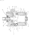
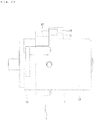
- Fig. 1 is a sectional view including a speed reduction mechanism, which shows a rotary electric machine according to Embodiment 1 of the present invention.
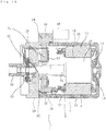
- Fig. 2 is an axial sectional view showing the rotary electric machine according to Embodiment 1 of the present invention.
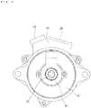
- Fig. 3 is a side view showing the rotary electric machine according to Embodiment 1 of the present invention.
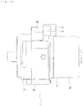
- Fig. 4 is a top view showing the rotary electric machine according to Embodiment 1 of the present invention.
- Fig. 5 is a front view showing the rotary electric machine according to Embodiment 1 of the present invention.
- Fig. 6 is a rear view showing the rotary electric machine according to Embodiment 1 of the present invention.
- a rotary electric machine 2 is a permanent magnet synchronous motor; and a three-phase stator winding 5 is wound around a stator core 3 which is formed by laminating magnetic steel sheets, via a resin-made insulator 4. Respective phase windings are connected in star or delta by winding terminals 7 incorporated in a resin-made terminal holder 6.
- Motor terminals 9 which are for electrically connecting to a driving device 8 are attached to the winding terminals 7.
- the stator core 3 is inserted with force into an iron-made frame 10 to form stator 11 of the motor.
- a bottom portion is provided on one end portion of the frame 10; and at a central portion of the bottom portion, a rear bearing box portion 14 for accommodating a bearding 13 which is for supporting one end of a rotor 12 is formed.
- Magnets 16 for forming a field system are attached to an outer peripheral portion of a shaft 15 of the rotor 12.
- the other end portion of the frame 10 is opened and a spigot joint portion 18 which is for joining to a housing 17 of the driving device 8 is formed.
- the housing 17 is formed by a resin molding; and the housing 17 is joined to a heat sink 19 of the driving device 8 on one end thereof.
- connection between the housing 17 and the heat sink 19 is made by clamping together with the frame 10.
- the heat sink 19 is formed by a die cast molding of aluminum alloy; and at a central portion of the heat sink, a front bearing box portion 21 for accommodating a front bearing 20 which is for supporting one end of the rotor is formed.
- the housing 17 and the heat sink 19 constitute a driving device accommodating portion 22.
- An attaching spigot joint portion 24 which is for attaching to a speed reduction mechanism 23 is provided on the other end portion of the heat sink 19.
- a resolver serving as a rotation sensor 25 is attached to a central portion on the front side of the heat sink 19.
- a boss 26 serving as a coupling which is for joining to the speed reduction mechanism 23 is attached on an end portion on the front side of the shaft 15.
- the driving device 8 has a glass epoxy-made control substrate 29 on which a microcomputer 27 and a field effect transistor (FET) driving circuit 28 are mounted and power circuits 30 on which a power element such as a power metal oxide semiconductor field effect transistor (MOSFET) is mounted.
- a lead frame 31 in which copper-made terminals (not shown in the drawing) through which electric power is supplied to the power circuits 30 and copper-made terminals (not shown in the drawing) which connect the power circuit 30 to other power circuit 30, the power circuit 30 to a capacitor (not shown in the drawing), and a coil to other coil (not shown in the drawing) are insert-molded with resin to be integrally formed.
- Copper-made terminals (not shown in the drawing) which connect the connector portion 34 to the control substrate 29 and the connector portion 34 to the power circuit 30 are also insert-molded in the lead frame 31.
- the power circuits 30 are provided so as to be firmly attached to an inside wall of the heat sink 19 and are configured to transmit heat emitted from the power elements to the heat sink 19.
- a power circuit 30 is provided with a power circuit signal terminal 32 and a power circuit motor terminal 33; the power circuit signal terminal 32 is connected to the control substrate 29; and the power circuit motor terminal 33 is connected to the motor terminal 9.
- the capacitor (not shown in the drawing) which absorbs ripples of a current flowing through the rotary electric machine 2 is accommodated in the heat sink 19, and is connected to the power circuit 30 via a terminal (not shown in the drawing). Furthermore, a coil (not shown in the drawing) which absorbs noise is also accommodated in the heat sink 19, and is connected to the connector portion 34 via a terminal (not shown in the drawing).
- a power supply connector 35 and a signal connector 36 are provided on the connector portion 34.
- the coaxially integrated driving device and rotary electric machine can be configured by stacking three portions of the heat sink 19, the housing 17, and the frame 10 in the axial direction of the rotary electric machine. Consequently, as compared before, the number of components is reduced, assembly becomes easier, and reduction in weight is achieved by resinification of components.
- the power circuit 30 is directly attached to the heat sink 19; and therefore, good heat dissipation properties can be secured in combination with a heat transmission effect from the heat sink 19 to the speed reduction mechanism 23.
- the frame 10 of the rotary electric machine 2 is attached to the heat sink 19 via the resin-made housing 17; and therefore, the vibration of the rotary electric machine 2 can be suppressed from being transmitted to the speed reduction mechanism 23 by the vibration damping effect of resin material and the generation of noise due to resonance with the speed reduction mechanism 23 and a member to which the speed reduction mechanism is attached can be suppressed.
- Fig. 7 is an axial sectional view showing a rotary electric machine according to Embodiment 2 of the present invention.
- Fig. 8 is a side view showing the rotary electric machine according to Embodiment 2 of the present invention.
- the rotary electric machine in this Embodiment 2 is different as compared to the aforementioned Embodiment 1 in that, a connector portion 34 and a lead frame 31 are integrally formed by a resin molding to be an integrated connector portion and lead frame 37.
- the rotary electric machine can be configured by stacking three portions of a heat sink 19, a housing 17, and a frame 10 in the axial direction of the rotary electric machine; and the lead frame 31 and the connector portion 34 are further integrated to be the integrated connector portion and lead frame 37. Consequently, as compared to the aforementioned conventional one, the number of components is further reduced, assembly becomes easier, and reduction in weight is achieved by resinification of components.
- a power circuit 30 is directly attached to the heat sink 19; and therefore, good heat dissipation properties can be secured in combination with a heat transmission effect from the heat sink 19 to a speed reduction mechanism 23.
- the frame 10 of the rotary electric machine 2 is attached to the heat sink 19 via the resin-made housing 17; and therefore, the vibration of the rotary electric machine 2 can be suppressed from being transmitted to the speed reduction mechanism 23 by the vibration damping effect of resin material and the generation of noise due to resonance with the speed reduction mechanism 23 and a member to which the speed reduction mechanism is attached can be suppressed.
- Example 3 will be described with reference to Fig. 9 and Fig. 10 .
- Fig. 9 is an axial sectional view showing a rotary electric machine according to Example 3.
- Fig. 10 is a side view showing the rotary electric machine according to Example 3.
- the rotary electric machine in this Example 3 is different as compared to the aforementioned Embodiment 1 in that, a housing 17 and a frame 10 are integrally formed by a resin molding to be an integrated housing and frame 38.
- the rotary electric machine can be configured by stacking two portions of a heat sink 19 and the integrated housing and frame 38 in the axial direction of the rotary electric machine; and the housing 17 and the frame 10 are further integrated to be the integrated housing and frame 38. Consequently, as compared to the aforementioned conventional one, the number of components is further reduced, assembly becomes easier, and reduction in weight is further achieved by resinification of also the frame 10 in addition to the housing 17.
- a power circuit 30 is directly attached to the heat sink 19; and therefore, good heat dissipation properties can be secured in combination with a heat transmission effect from the heat sink 19 to a speed reduction mechanism 23.
- the frame 10 of the rotary electric machine 2 is made of resin and is integrated with the housing 17 to be the integrated housing and frame 38; and consequently, rigidity of the frame is improved and the vibration of the rotary electric machine 2 can be suppressed.
- the rotary electric machine 2 is attached to the heat sink 19 via the resin-made integrated housing and frame 38; and therefore, the vibration of the rotary electric machine 2 can be suppressed from being transmitted to the speed reduction mechanism 23 by the vibration damping effect of resin material and the generation of noise due to resonance with the speed reduction mechanism 23 and a member to which the speed reduction mechanism is attached can be suppressed.
- Example 4 will be described with reference to Fig. 11 and Fig. 12 .
- Fig. 11 is an axial sectional view showing a rotary electric machine according to Example 4.
- Fig. 12 is a side view showing the rotary electric machine according to Example 4.
- the rotary electric machine in this Example 4 is different as compared to the aforementioned Embodiment 1 in that, a lead frame 31 and a housing 17 are integrally formed by a resin molding to be an integrated lead frame and housing 39.
- the rotary electric machine can be configured by stacking three portions of a heat sink 19, the integrated lead frame and housing 39, and a frame 10 in the axial direction of the rotary electric machine; and the lead frame 31 and the housing 17 are further integrated to be the integrated lead frame and housing 39. Consequently, as compared to the aforementioned conventional one, the number of components is further reduced, assembly becomes easier, and reduction in weight is achieved by resinification of components.
- a power circuit 30 is directly attached to the heat sink 19; and therefore, good heat dissipation properties can be secured, in combination with a heat transmission effect from the heat sink 19 to a speed reduction mechanism 23.
- the frame 10 of the rotary electric machine 2 is attached to the heat sink 19 via the resin-made integrated lead frame and housing 39; and therefore, the vibration of the rotary electric machine 2 can be suppressed from being transmitted to the speed reduction mechanism 23 by the vibration damping effect of resin material and the generation of noise due to resonance with the speed reduction mechanism 23 and a member to which the speed reduction mechanism is attached can be suppressed.
- Embodiment 5 of the present invention will be described with reference to Fig. 13 and Fig. 14 .
- Fig. 13 is an axial sectional view showing a rotary electric machine according to Embodiment 5 of the present invention.
- Fig. 14 is a side view showing the rotary electric machine according to Embodiment 5 of the present invention.
- the rotary electric machine in this Embodiment 5 is different as compared to the aforementioned Embodiment 1 in that, a connector portion 34 and a housing 17 are integrally formed by a resin molding to be an integrated connector portion and housing 40.
- the rotary electric machine can be configured by stacking three portions of a heat sink 19, the integrated connector portion and housing 40, and a frame 10 in the axial direction of the rotary electric machine; and the connector portion 34 and the housing 17 are further integrated to be the integrated connector portion and housing 40. Consequently, as compared to the aforementioned conventional one, the number of components is further reduced, assembly becomes easier, and reduction in weight is achieved by resinification of components.
- a power circuit 30 is directly attached to the heat sink 19; and therefore, good heat dissipation properties can be secured in combination with a heat transmission effect from the heat sink 19 to a speed reduction mechanism 23.
- the frame 10 of the rotary electric machine 2 is attached to the heat sink 19 via the resin-made integrated connector portion and housing 40; and therefore, the vibration of the rotary electric machine 2 can be suppressed from being transmitted to the speed reduction mechanism 23 by the vibration damping effect of resin material and the generation of noise due to resonance with the speed reduction mechanism 23 and a member to which the speed reduction mechanism is attached can be suppressed.
- Example 6 will be described with reference to Fig. 15 and Fig. 16 .
- Fig. 15 is an axial sectional view showing a rotary electric machine according to Example 6.
- Fig. 16 is a side view showing the rotary electric machine according to Example 6.
- the rotary electric machine in this Example 6 is different as compared to the aforementioned Embodiment 2 in that, in addition to that in which a connector portion 34 and a lead frame 31 are integrally formed by a resin molding to be an integrated connector portion and lead frame 37, a housing 17 and a frame 10 are integrally formed by a resin molding to be an integrated housing and frame 38.
- the rotary electric machine can be configured by stacking two portions of a heat sink 19 and the integrated housing and frame 38 in the axial direction of the rotary electric machine.
- the housing 17 and the frame 10 are integrated to be the integrated housing and frame 38. Consequently, as compared to the aforementioned conventional one, the number of components is further reduced, assembly becomes easier, and reduction in weight is further achieved by resinification of also the frame in addition to the housing.
- a power circuit 30 is directly attached to the heat sink 19; and therefore, good heat dissipation properties can be secured in combination with a heat transmission effect from the heat sink 19 to a speed reduction mechanism 23.
- the frame of the rotary electric machine 2 is made of resin and is integrated with the housing to be the integrated housing and frame 38; and consequently, rigidity of the frame is improved and the vibration of the rotary electric machine 2 can be further suppressed.
- the rotary electric machine 2 is attached to the heat sink 19 via the resin-made integrated housing and frame 38; and therefore, the vibration of the rotary electric machine 2 can be suppressed from being transmitted to the speed reduction mechanism 23 by the vibration damping effect of resin material and the generation of noise due to resonance with the speed reduction mechanism 23 and a member to which the speed reduction mechanism is attached can be suppressed.
- Example 7 will be described with reference to Fig. 17 and Fig. 18 .
- Fig. 17 is an axial sectional view showing a rotary electric machine according to Example 7.
- Fig. 18 is a side view showing the rotary electric machine according to Example 7.
- the rotary electric machine in this Example 7 is different as compared to the aforementioned Embodiment 2 in that, in addition to a connector portion 34 and a lead frame 31, a housing 17 is further integrally formed by a resin molding to be an integrated connector portion, lead frame, and housing 41.
- the rotary electric machine can be configured by stacking three portions of a heat sink 19; the integrated connector portion, lead frame, and housing 41; and a frame 10 in the axial direction of the rotary electric machine.
- the housing 17 is further integrated to be the integrated connector portion, lead frame, and housing 41. Consequently, as compared to the aforementioned conventional one, the number of components is further reduced, assembly becomes easier, and reduction in weight is achieved by resinification of components.
- a power circuit 30 is directly attached to the heat sink 19; and therefore, good heat dissipation properties can be secured in combination with a heat transmission effect from the heat sink 19 to a speed reduction mechanism 23.
- the frame 10 of the rotary electric machine 2 is attached to the heat sink 19 via the resin-made integrated connector portion, lead frame, and housing 41; and therefore, the vibration of the rotary electric machine 2 can be suppressed from being transmitted to the speed reduction mechanism 23 by the vibration damping effect of resin material and the generation of noise due to resonance with the speed reduction mechanism 23 and a member to which the speed reduction mechanism is attached can be suppressed.
- Example 8 will be described with reference to Fig. 19 and Fig. 20 .
- Fig. 19 is an axial sectional view showing a rotary electric machine according to Example 8.
- Fig. 20 is a side view showing the rotary electric machine according to Example 8.
- the rotary electric machine in this Example 8 is different as compared to the aforementioned Example 3 in that, in addition to a housing 17 and a frame 10, a connector portion 34 is further integrally formed by a resin molding to be an integrated connector portion, housing, and frame 42.
- the rotary electric machine can be configured by stacking two portions of a heat sink 19 and the integrated connector portion, housing, and frame 42 in the axial direction of the rotary electric machine.
- the connector portion 34 is integrated to be the integrated connector portion, housing, and frame 42. Consequently, as compared to the aforementioned conventional one, the number of components is further reduced, assembly becomes easier, and reduction in weight is further achieved by resinification of also the frame in addition to the housing.
- a power circuit 30 is directly attached to the heat sink 19; and therefore, good heat dissipation properties can be secured in combination with a heat transmission effect from the heat sink 19 to a speed reduction mechanism 23.
- the frame of the rotary electric machine 2 is made of resin and is integrated with the housing to be the integrated connector portion, housing, and frame 42; and consequently, rigidity of the frame is improved and the vibration of the rotary electric machine 2 can be further suppressed.
- the rotary electric machine 2 is attached to the heat sink 19 via the resin-made integrated connector portion, housing, and frame 42; and therefore, the vibration of the rotary electric machine 2 can be suppressed from being transmitted to the speed reduction mechanism 23 by the vibration damping effect of resin material and the generation of noise due to resonance with the speed reduction mechanism 23 and a member to which the speed reduction mechanism is attached can be suppressed.
- Embodiment 9 is one in which any of the rotary electric machine of the aforementioned Embodiments and Examples is applied to an electric power steering apparatus.
- the vibration of a rotary electric machine 2 can be suppressed from being transmitted to a speed reduction mechanism 23, the generation of noise due to resonance with the speed reduction mechanism 23 and a vehicle body to which the speed reduction mechanism is attached can be suppressed, and the silent properties of a vehicle can be improved.
- the rotary electric machine is lightweight and therefore reduction in weight of the vehicle is achieved; and therefore, effects exist that fuel consumption of the vehicle is improved and the amount of emission of carbon dioxide can be reduced.
- the present invention is suitable for achieving a rotary electric machine which is lightweight, is easy in assembly, can reduce the number of components, and can suppress the vibration of a motor from being transmitted to members on the other side while securing the heat dissipation properties of a power circuit.
Landscapes
- Engineering & Computer Science (AREA)
- Power Engineering (AREA)
- Microelectronics & Electronic Packaging (AREA)
- Motor Or Generator Frames (AREA)
Claims (9)
- Machine électrique rotative comprenant :un dissipateur thermique (19) réalisé en métal et monté avec un circuit d'alimentation (30) ;un cadre (10) destiné à contenir un rotor (12) et un noyau de stator (3) ;un boîtier (17), le cadre (10) étant fixé au dissipateur thermique (19) par l'intermédiaire du boîtier (17), ledit boîtier (17) étant constitué d'une résine, un dispositif d'entraînement (8) comprenant un support de commande (29) et le circuit d'alimentation (30) étant logé dans une partie de réception de dispositif d'entraînement (22) constituée par le boîtier (17) et le dissipateur thermique (19); etledit dissipateur thermique (19), ledit boîtier (17) et ledit cadre (10) étant configurés d'un seul tenant et de façon coaxiale, et un cadre conducteur (31) est connecté audit circuit d'alimentation (30),ladite machine électrique rotative comprenant en outre une partie de connecteur (34) connectée audit cadre conducteur (31) et étant destinée à une connexion vers l'extérieur; etun appui avant (20) étant ménagé dans une partie centrale du dissipateur thermique (19) et supportant une extrémité du rotor (12).
- Machine électrique rotative selon la revendication 1,
dans laquelle ledit cadre connecteur (31) et ladite partie de connecteur (34) sont formés d'un seul tenant par moulage de résine pour constituer une partie de connecteur et un cadre connecteur intégrés (34). - Machine électrique rotative selon la revendication 1,
dans laquelle ledit boîtier (17) et ledit cadre (10) sont formés d'un seul tenant par moulage de résine pour constituer un boîtier et un cadre intégrés (38). - Machine électrique rotative selon la revendication 1,
dans laquelle ledit cadre connecteur (31) et ledit boîtier (17) sont formés d'un seul tenant par moulage de résine pour constituer un cadre connecteur et un boîtier intégrés (39). - Machine électrique rotative selon la revendication 1,
dans laquelle ladite partie de connecteur (34) et ledit boîtier (17) sont formés d'un seul tenant par moulage de résine pour constituer une partie de connecteur et un boîtier intégrés (40). - Machine électrique rotative selon la revendication 2,
dans laquelle ledit boîtier (17) et ledit cadre (10) sont formées d'un seul tenant par moulage de résine pour constituer un boîtier et un cadre intégrés (38). - Machine électrique rotative selon la revendication 2,
dans laquelle, en plus de ladite partie de connecteur (34) et dudit cadre connecteur (31), ledit boîtier (17) est en outre formé d'un seul tenant par moulage de résine pour constituer une partie de connecteur, une structure de connexion et un boîtier intégrés (41). - Machine électrique rotative selon la revendication 3,
dans laquelle, en plus dudit boîtier (17) et dudit cadre (10), ladite partie de connecteur (34) est en outre formée d'un seul tenant par moulage de résine pour constituer une partie de connecteur, un boîtier et un cadre intégrés (42). - Machine électrique rotative selon l'une quelconque des revendications 1 à la revendication 8,
dans laquelle ladite machine électrique rotative est appliquée à un appareil de direction assistée électrique.
Applications Claiming Priority (1)
| Application Number | Priority Date | Filing Date | Title |
|---|---|---|---|
| PCT/JP2011/059717 WO2012144029A1 (fr) | 2011-04-20 | 2011-04-20 | Machine électrique rotative |
Publications (3)
| Publication Number | Publication Date |
|---|---|
| EP2701287A1 EP2701287A1 (fr) | 2014-02-26 |
| EP2701287A4 EP2701287A4 (fr) | 2015-11-25 |
| EP2701287B1 true EP2701287B1 (fr) | 2016-12-21 |
Family
ID=47041179
Family Applications (1)
| Application Number | Title | Priority Date | Filing Date |
|---|---|---|---|
| EP11864109.1A Not-in-force EP2701287B1 (fr) | 2011-04-20 | 2011-04-20 | Machine électrique rotative |
Country Status (5)
| Country | Link |
|---|---|
| US (1) | US9252638B2 (fr) |
| EP (1) | EP2701287B1 (fr) |
| JP (1) | JP5611452B2 (fr) |
| CN (1) | CN103339838B (fr) |
| WO (1) | WO2012144029A1 (fr) |
Families Citing this family (12)
| Publication number | Priority date | Publication date | Assignee | Title |
|---|---|---|---|---|
| USD707739S1 (en) * | 2013-06-20 | 2014-06-24 | Asmo Co., Ltd. | Motor actuator |
| USD706325S1 (en) * | 2013-06-20 | 2014-06-03 | Asmo Co., Ltd. | Motor actuator |
| WO2015056294A1 (fr) * | 2013-10-15 | 2015-04-23 | 株式会社安川電機 | Machine électrique rotative |
| JP6372756B2 (ja) * | 2014-12-26 | 2018-08-15 | パナソニックIpマネジメント株式会社 | モータおよびそれを備えた電動工具 |
| JP6482353B2 (ja) * | 2015-03-31 | 2019-03-13 | 株式会社村上開明堂 | 車両用電動格納式視認装置 |
| JP5951067B1 (ja) * | 2015-04-10 | 2016-07-13 | 三菱電機株式会社 | 電動パワーステアリング装置 |
| USD774576S1 (en) * | 2015-04-20 | 2016-12-20 | SZ DJI Technology Co., Ltd. | Motor |
| US10756600B2 (en) * | 2016-02-24 | 2020-08-25 | Hitachi, Ltd. | Axial gap rotary electric machine |
| CN112425041B (zh) * | 2018-07-19 | 2024-05-31 | 索尤若驱动有限及两合公司 | 具有接线单元的电机和用于制造具有接线单元的电机的方法 |
| CN111106698A (zh) * | 2018-10-29 | 2020-05-05 | 日本电产株式会社 | 马达以及减速装置 |
| JP7272181B2 (ja) * | 2019-08-27 | 2023-05-12 | 株式会社デンソーダイシン | 絞り弁装置及び絞り弁装置の製造方法 |
| GB2617398A (en) | 2022-04-08 | 2023-10-11 | Zf Automotive Uk Ltd | A steering column assembly for a vehicle |
Family Cites Families (14)
| Publication number | Priority date | Publication date | Assignee | Title |
|---|---|---|---|---|
| JPS6137580A (ja) * | 1984-07-30 | 1986-02-22 | Nissan Motor Co Ltd | 電動式動力舵取り装置 |
| JP2534683Y2 (ja) * | 1990-07-16 | 1997-05-07 | 愛三工業株式会社 | ステップモータのターミナル固定構造 |
| US5939807A (en) * | 1997-12-16 | 1999-08-17 | Reliance Electric Industrial Company | Cap mounted drive for a brushless DC motor |
| JP3774624B2 (ja) * | 2000-10-18 | 2006-05-17 | 三菱電機株式会社 | 電動パワーステアリング装置 |
| JP2002254357A (ja) * | 2001-03-01 | 2002-09-10 | Hitachi Koki Co Ltd | 電動工具 |
| WO2004040734A1 (fr) | 2002-10-31 | 2004-05-13 | Nsk Ltd. | Dispositif de direction assistee electrique |
| JP2005306050A (ja) | 2002-10-31 | 2005-11-04 | Nsk Ltd | 電動パワーステアリング装置 |
| JP2005312086A (ja) | 2002-10-31 | 2005-11-04 | Nsk Ltd | 電動パワーステアリング装置 |
| JP2007037262A (ja) | 2005-07-26 | 2007-02-08 | Mitsubishi Electric Corp | インバータ一体型回転電機 |
| JP4353951B2 (ja) * | 2006-03-06 | 2009-10-28 | 三菱電機株式会社 | 電動式パワーステアリング装置 |
| JP5011801B2 (ja) * | 2006-04-11 | 2012-08-29 | 日本精工株式会社 | 電動パワーステアリング装置 |
| JP2009298246A (ja) * | 2008-06-11 | 2009-12-24 | Jtekt Corp | 電動パワーステアリング装置 |
| JP4856686B2 (ja) * | 2008-10-03 | 2012-01-18 | 株式会社東海理化電機製作所 | 電動ステアリングロック装置及びモータ制振構造 |
| JP5603045B2 (ja) * | 2009-09-24 | 2014-10-08 | 三菱電機株式会社 | 電動パワーステアリング装置用モータ装置 |
-
2011
- 2011-04-20 WO PCT/JP2011/059717 patent/WO2012144029A1/fr not_active Ceased
- 2011-04-20 EP EP11864109.1A patent/EP2701287B1/fr not_active Not-in-force
- 2011-04-20 CN CN201180066386.0A patent/CN103339838B/zh not_active Expired - Fee Related
- 2011-04-20 US US13/991,507 patent/US9252638B2/en not_active Expired - Fee Related
- 2011-04-20 JP JP2013510776A patent/JP5611452B2/ja not_active Expired - Fee Related
Non-Patent Citations (1)
| Title |
|---|
| None * |
Also Published As
| Publication number | Publication date |
|---|---|
| EP2701287A4 (fr) | 2015-11-25 |
| WO2012144029A1 (fr) | 2012-10-26 |
| JPWO2012144029A1 (ja) | 2014-07-28 |
| EP2701287A1 (fr) | 2014-02-26 |
| US20130257185A1 (en) | 2013-10-03 |
| JP5611452B2 (ja) | 2014-10-22 |
| CN103339838A (zh) | 2013-10-02 |
| CN103339838B (zh) | 2016-05-25 |
| US9252638B2 (en) | 2016-02-02 |
Similar Documents
| Publication | Publication Date | Title |
|---|---|---|
| US9252638B2 (en) | Rotary electric machine | |
| KR101204624B1 (ko) | 제어 장치 일체형 전동 파워 스티어링 장치용 모터 및 전동 파워 스티어링 장치 | |
| US9531232B2 (en) | Rotating electrical machine incorporating drive device | |
| CN103534908B (zh) | 电动动力转向装置用电动机驱动装置 | |
| CN102812623B (zh) | 电动式驱动装置和具有该电动式驱动装置的电动式动力转向装置 | |
| CN101557141B (zh) | 电动动力转向装置用电动机及电动动力转向装置 | |
| US9935526B2 (en) | Electric rotating machine | |
| JP5410194B2 (ja) | 駆動回路内蔵型モータ | |
| JP6157652B2 (ja) | 永久磁石型モータ | |
| WO2014054155A1 (fr) | Machine électrique rotative comprenant un dispositif de commande d'entraînement intégré | |
| CN103404005A (zh) | 电动机驱动装置 | |
| JP5489224B2 (ja) | モータ、および、それを用いた電動パワーステアリング装置 | |
| US9118236B2 (en) | Motor for electric power steering | |
| JP2010011601A (ja) | 電動モータ用ターミナルユニット | |
| JP5645974B2 (ja) | 電動パワーステアリング用電動モータ装置及び電動パワーステアリング装置 |
Legal Events
| Date | Code | Title | Description |
|---|---|---|---|
| PUAI | Public reference made under article 153(3) epc to a published international application that has entered the european phase |
Free format text: ORIGINAL CODE: 0009012 |
|
| 17P | Request for examination filed |
Effective date: 20130619 |
|
| AK | Designated contracting states |
Kind code of ref document: A1 Designated state(s): AL AT BE BG CH CY CZ DE DK EE ES FI FR GB GR HR HU IE IS IT LI LT LU LV MC MK MT NL NO PL PT RO RS SE SI SK SM TR |
|
| DAX | Request for extension of the european patent (deleted) | ||
| RA4 | Supplementary search report drawn up and despatched (corrected) |
Effective date: 20151027 |
|
| RIC1 | Information provided on ipc code assigned before grant |
Ipc: H02K 5/173 20060101ALI20151021BHEP Ipc: H02K 5/06 20060101ALI20151021BHEP Ipc: H02K 5/08 20060101ALI20151021BHEP Ipc: H02K 3/50 20060101ALI20151021BHEP Ipc: H02K 11/00 20060101AFI20151021BHEP Ipc: H02K 5/15 20060101ALI20151021BHEP Ipc: H02K 7/116 20060101ALI20151021BHEP Ipc: H02K 5/22 20060101ALI20151021BHEP Ipc: H02K 5/02 20060101ALI20151021BHEP |
|
| REG | Reference to a national code |
Ref country code: DE Ref legal event code: R079 Ref document number: 602011033741 Country of ref document: DE Free format text: PREVIOUS MAIN CLASS: H02K0011000000 Ipc: H02K0011225000 |
|
| RIC1 | Information provided on ipc code assigned before grant |
Ipc: H02K 5/22 20060101ALI20160629BHEP Ipc: H02K 5/02 20060101ALI20160629BHEP Ipc: H02K 7/116 20060101ALI20160629BHEP Ipc: H02K 11/33 20160101ALI20160629BHEP Ipc: H02K 11/225 20160101AFI20160629BHEP Ipc: H02K 3/50 20060101ALI20160629BHEP Ipc: H02K 5/08 20060101ALI20160629BHEP Ipc: H02K 5/15 20060101ALI20160629BHEP Ipc: H02K 5/173 20060101ALI20160629BHEP Ipc: H02K 5/06 20060101ALI20160629BHEP |
|
| GRAP | Despatch of communication of intention to grant a patent |
Free format text: ORIGINAL CODE: EPIDOSNIGR1 |
|
| INTG | Intention to grant announced |
Effective date: 20160810 |
|
| GRAS | Grant fee paid |
Free format text: ORIGINAL CODE: EPIDOSNIGR3 |
|
| GRAA | (expected) grant |
Free format text: ORIGINAL CODE: 0009210 |
|
| AK | Designated contracting states |
Kind code of ref document: B1 Designated state(s): AL AT BE BG CH CY CZ DE DK EE ES FI FR GB GR HR HU IE IS IT LI LT LU LV MC MK MT NL NO PL PT RO RS SE SI SK SM TR |
|
| REG | Reference to a national code |
Ref country code: GB Ref legal event code: FG4D |
|
| REG | Reference to a national code |
Ref country code: CH Ref legal event code: EP |
|
| REG | Reference to a national code |
Ref country code: IE Ref legal event code: FG4D |
|
| REG | Reference to a national code |
Ref country code: AT Ref legal event code: REF Ref document number: 856247 Country of ref document: AT Kind code of ref document: T Effective date: 20170115 |
|
| REG | Reference to a national code |
Ref country code: DE Ref legal event code: R096 Ref document number: 602011033741 Country of ref document: DE |
|
| PG25 | Lapsed in a contracting state [announced via postgrant information from national office to epo] |
Ref country code: LV Free format text: LAPSE BECAUSE OF FAILURE TO SUBMIT A TRANSLATION OF THE DESCRIPTION OR TO PAY THE FEE WITHIN THE PRESCRIBED TIME-LIMIT Effective date: 20161221 |
|
| REG | Reference to a national code |
Ref country code: FR Ref legal event code: PLFP Year of fee payment: 7 |
|
| REG | Reference to a national code |
Ref country code: LT Ref legal event code: MG4D |
|
| REG | Reference to a national code |
Ref country code: NL Ref legal event code: MP Effective date: 20161221 |
|
| PG25 | Lapsed in a contracting state [announced via postgrant information from national office to epo] |
Ref country code: SE Free format text: LAPSE BECAUSE OF FAILURE TO SUBMIT A TRANSLATION OF THE DESCRIPTION OR TO PAY THE FEE WITHIN THE PRESCRIBED TIME-LIMIT Effective date: 20161221 Ref country code: GR Free format text: LAPSE BECAUSE OF FAILURE TO SUBMIT A TRANSLATION OF THE DESCRIPTION OR TO PAY THE FEE WITHIN THE PRESCRIBED TIME-LIMIT Effective date: 20170322 Ref country code: NO Free format text: LAPSE BECAUSE OF FAILURE TO SUBMIT A TRANSLATION OF THE DESCRIPTION OR TO PAY THE FEE WITHIN THE PRESCRIBED TIME-LIMIT Effective date: 20170321 Ref country code: LT Free format text: LAPSE BECAUSE OF FAILURE TO SUBMIT A TRANSLATION OF THE DESCRIPTION OR TO PAY THE FEE WITHIN THE PRESCRIBED TIME-LIMIT Effective date: 20161221 |
|
| REG | Reference to a national code |
Ref country code: AT Ref legal event code: MK05 Ref document number: 856247 Country of ref document: AT Kind code of ref document: T Effective date: 20161221 |
|
| PG25 | Lapsed in a contracting state [announced via postgrant information from national office to epo] |
Ref country code: FI Free format text: LAPSE BECAUSE OF FAILURE TO SUBMIT A TRANSLATION OF THE DESCRIPTION OR TO PAY THE FEE WITHIN THE PRESCRIBED TIME-LIMIT Effective date: 20161221 Ref country code: RS Free format text: LAPSE BECAUSE OF FAILURE TO SUBMIT A TRANSLATION OF THE DESCRIPTION OR TO PAY THE FEE WITHIN THE PRESCRIBED TIME-LIMIT Effective date: 20161221 Ref country code: HR Free format text: LAPSE BECAUSE OF FAILURE TO SUBMIT A TRANSLATION OF THE DESCRIPTION OR TO PAY THE FEE WITHIN THE PRESCRIBED TIME-LIMIT Effective date: 20161221 |
|
| PG25 | Lapsed in a contracting state [announced via postgrant information from national office to epo] |
Ref country code: NL Free format text: LAPSE BECAUSE OF FAILURE TO SUBMIT A TRANSLATION OF THE DESCRIPTION OR TO PAY THE FEE WITHIN THE PRESCRIBED TIME-LIMIT Effective date: 20161221 |
|
| PG25 | Lapsed in a contracting state [announced via postgrant information from national office to epo] |
Ref country code: CZ Free format text: LAPSE BECAUSE OF FAILURE TO SUBMIT A TRANSLATION OF THE DESCRIPTION OR TO PAY THE FEE WITHIN THE PRESCRIBED TIME-LIMIT Effective date: 20161221 Ref country code: EE Free format text: LAPSE BECAUSE OF FAILURE TO SUBMIT A TRANSLATION OF THE DESCRIPTION OR TO PAY THE FEE WITHIN THE PRESCRIBED TIME-LIMIT Effective date: 20161221 Ref country code: IS Free format text: LAPSE BECAUSE OF FAILURE TO SUBMIT A TRANSLATION OF THE DESCRIPTION OR TO PAY THE FEE WITHIN THE PRESCRIBED TIME-LIMIT Effective date: 20170421 Ref country code: SK Free format text: LAPSE BECAUSE OF FAILURE TO SUBMIT A TRANSLATION OF THE DESCRIPTION OR TO PAY THE FEE WITHIN THE PRESCRIBED TIME-LIMIT Effective date: 20161221 Ref country code: RO Free format text: LAPSE BECAUSE OF FAILURE TO SUBMIT A TRANSLATION OF THE DESCRIPTION OR TO PAY THE FEE WITHIN THE PRESCRIBED TIME-LIMIT Effective date: 20161221 |
|
| PG25 | Lapsed in a contracting state [announced via postgrant information from national office to epo] |
Ref country code: PT Free format text: LAPSE BECAUSE OF FAILURE TO SUBMIT A TRANSLATION OF THE DESCRIPTION OR TO PAY THE FEE WITHIN THE PRESCRIBED TIME-LIMIT Effective date: 20170421 Ref country code: AT Free format text: LAPSE BECAUSE OF FAILURE TO SUBMIT A TRANSLATION OF THE DESCRIPTION OR TO PAY THE FEE WITHIN THE PRESCRIBED TIME-LIMIT Effective date: 20161221 Ref country code: BG Free format text: LAPSE BECAUSE OF FAILURE TO SUBMIT A TRANSLATION OF THE DESCRIPTION OR TO PAY THE FEE WITHIN THE PRESCRIBED TIME-LIMIT Effective date: 20170321 Ref country code: IT Free format text: LAPSE BECAUSE OF FAILURE TO SUBMIT A TRANSLATION OF THE DESCRIPTION OR TO PAY THE FEE WITHIN THE PRESCRIBED TIME-LIMIT Effective date: 20161221 Ref country code: ES Free format text: LAPSE BECAUSE OF FAILURE TO SUBMIT A TRANSLATION OF THE DESCRIPTION OR TO PAY THE FEE WITHIN THE PRESCRIBED TIME-LIMIT Effective date: 20161221 Ref country code: PL Free format text: LAPSE BECAUSE OF FAILURE TO SUBMIT A TRANSLATION OF THE DESCRIPTION OR TO PAY THE FEE WITHIN THE PRESCRIBED TIME-LIMIT Effective date: 20161221 Ref country code: BE Free format text: LAPSE BECAUSE OF FAILURE TO SUBMIT A TRANSLATION OF THE DESCRIPTION OR TO PAY THE FEE WITHIN THE PRESCRIBED TIME-LIMIT Effective date: 20161221 Ref country code: SM Free format text: LAPSE BECAUSE OF FAILURE TO SUBMIT A TRANSLATION OF THE DESCRIPTION OR TO PAY THE FEE WITHIN THE PRESCRIBED TIME-LIMIT Effective date: 20161221 |
|
| REG | Reference to a national code |
Ref country code: DE Ref legal event code: R097 Ref document number: 602011033741 Country of ref document: DE |
|
| PLBE | No opposition filed within time limit |
Free format text: ORIGINAL CODE: 0009261 |
|
| STAA | Information on the status of an ep patent application or granted ep patent |
Free format text: STATUS: NO OPPOSITION FILED WITHIN TIME LIMIT |
|
| 26N | No opposition filed |
Effective date: 20170922 |
|
| PG25 | Lapsed in a contracting state [announced via postgrant information from national office to epo] |
Ref country code: DK Free format text: LAPSE BECAUSE OF FAILURE TO SUBMIT A TRANSLATION OF THE DESCRIPTION OR TO PAY THE FEE WITHIN THE PRESCRIBED TIME-LIMIT Effective date: 20161221 |
|
| REG | Reference to a national code |
Ref country code: CH Ref legal event code: PL |
|
| GBPC | Gb: european patent ceased through non-payment of renewal fee |
Effective date: 20170420 |
|
| REG | Reference to a national code |
Ref country code: IE Ref legal event code: MM4A |
|
| PG25 | Lapsed in a contracting state [announced via postgrant information from national office to epo] |
Ref country code: MC Free format text: LAPSE BECAUSE OF FAILURE TO SUBMIT A TRANSLATION OF THE DESCRIPTION OR TO PAY THE FEE WITHIN THE PRESCRIBED TIME-LIMIT Effective date: 20161221 |
|
| PG25 | Lapsed in a contracting state [announced via postgrant information from national office to epo] |
Ref country code: SI Free format text: LAPSE BECAUSE OF FAILURE TO SUBMIT A TRANSLATION OF THE DESCRIPTION OR TO PAY THE FEE WITHIN THE PRESCRIBED TIME-LIMIT Effective date: 20161221 Ref country code: LI Free format text: LAPSE BECAUSE OF NON-PAYMENT OF DUE FEES Effective date: 20170430 Ref country code: CH Free format text: LAPSE BECAUSE OF NON-PAYMENT OF DUE FEES Effective date: 20170430 Ref country code: GB Free format text: LAPSE BECAUSE OF NON-PAYMENT OF DUE FEES Effective date: 20170420 Ref country code: LU Free format text: LAPSE BECAUSE OF NON-PAYMENT OF DUE FEES Effective date: 20170420 |
|
| REG | Reference to a national code |
Ref country code: FR Ref legal event code: PLFP Year of fee payment: 8 |
|
| PG25 | Lapsed in a contracting state [announced via postgrant information from national office to epo] |
Ref country code: IE Free format text: LAPSE BECAUSE OF NON-PAYMENT OF DUE FEES Effective date: 20170420 |
|
| PG25 | Lapsed in a contracting state [announced via postgrant information from national office to epo] |
Ref country code: MT Free format text: LAPSE BECAUSE OF NON-PAYMENT OF DUE FEES Effective date: 20170420 |
|
| PG25 | Lapsed in a contracting state [announced via postgrant information from national office to epo] |
Ref country code: HU Free format text: LAPSE BECAUSE OF FAILURE TO SUBMIT A TRANSLATION OF THE DESCRIPTION OR TO PAY THE FEE WITHIN THE PRESCRIBED TIME-LIMIT; INVALID AB INITIO Effective date: 20110420 |
|
| PG25 | Lapsed in a contracting state [announced via postgrant information from national office to epo] |
Ref country code: CY Free format text: LAPSE BECAUSE OF NON-PAYMENT OF DUE FEES Effective date: 20161221 |
|
| PG25 | Lapsed in a contracting state [announced via postgrant information from national office to epo] |
Ref country code: MK Free format text: LAPSE BECAUSE OF FAILURE TO SUBMIT A TRANSLATION OF THE DESCRIPTION OR TO PAY THE FEE WITHIN THE PRESCRIBED TIME-LIMIT Effective date: 20161221 |
|
| PG25 | Lapsed in a contracting state [announced via postgrant information from national office to epo] |
Ref country code: TR Free format text: LAPSE BECAUSE OF FAILURE TO SUBMIT A TRANSLATION OF THE DESCRIPTION OR TO PAY THE FEE WITHIN THE PRESCRIBED TIME-LIMIT Effective date: 20161221 |
|
| PG25 | Lapsed in a contracting state [announced via postgrant information from national office to epo] |
Ref country code: AL Free format text: LAPSE BECAUSE OF FAILURE TO SUBMIT A TRANSLATION OF THE DESCRIPTION OR TO PAY THE FEE WITHIN THE PRESCRIBED TIME-LIMIT Effective date: 20161221 |
|
| PGFP | Annual fee paid to national office [announced via postgrant information from national office to epo] |
Ref country code: FR Payment date: 20220308 Year of fee payment: 12 |
|
| PGFP | Annual fee paid to national office [announced via postgrant information from national office to epo] |
Ref country code: DE Payment date: 20220302 Year of fee payment: 12 |
|
| REG | Reference to a national code |
Ref country code: DE Ref legal event code: R119 Ref document number: 602011033741 Country of ref document: DE |
|
| PG25 | Lapsed in a contracting state [announced via postgrant information from national office to epo] |
Ref country code: FR Free format text: LAPSE BECAUSE OF NON-PAYMENT OF DUE FEES Effective date: 20230430 Ref country code: DE Free format text: LAPSE BECAUSE OF NON-PAYMENT OF DUE FEES Effective date: 20231103 |