EP2702256B1 - Verbrennungsmotor und verfahren zum einspritzen von kraftstoff in einen brennraum eines verbrennungsmotors - Google Patents
Verbrennungsmotor und verfahren zum einspritzen von kraftstoff in einen brennraum eines verbrennungsmotors Download PDFInfo
- Publication number
- EP2702256B1 EP2702256B1 EP12724888.8A EP12724888A EP2702256B1 EP 2702256 B1 EP2702256 B1 EP 2702256B1 EP 12724888 A EP12724888 A EP 12724888A EP 2702256 B1 EP2702256 B1 EP 2702256B1
- Authority
- EP
- European Patent Office
- Prior art keywords
- angle
- jet
- lies
- central axis
- injector
- Prior art date
- Legal status (The legal status is an assumption and is not a legal conclusion. Google has not performed a legal analysis and makes no representation as to the accuracy of the status listed.)
- Active
Links
Images


Classifications
-
- F—MECHANICAL ENGINEERING; LIGHTING; HEATING; WEAPONS; BLASTING
- F02—COMBUSTION ENGINES; HOT-GAS OR COMBUSTION-PRODUCT ENGINE PLANTS
- F02M—SUPPLYING COMBUSTION ENGINES IN GENERAL WITH COMBUSTIBLE MIXTURES OR CONSTITUENTS THEREOF
- F02M61/00—Fuel-injectors not provided for in groups F02M39/00 - F02M57/00 or F02M67/00
- F02M61/16—Details not provided for in, or of interest apart from, the apparatus of groups F02M61/02 - F02M61/14
- F02M61/18—Injection nozzles, e.g. having valve seats; Details of valve member seated ends, not otherwise provided for
- F02M61/1806—Injection nozzles, e.g. having valve seats; Details of valve member seated ends, not otherwise provided for characterised by the arrangement of discharge orifices, e.g. orientation or size
-
- F—MECHANICAL ENGINEERING; LIGHTING; HEATING; WEAPONS; BLASTING
- F02—COMBUSTION ENGINES; HOT-GAS OR COMBUSTION-PRODUCT ENGINE PLANTS
- F02B—INTERNAL-COMBUSTION PISTON ENGINES; COMBUSTION ENGINES IN GENERAL
- F02B23/00—Other engines characterised by special shape or construction of combustion chambers to improve operation
- F02B23/08—Other engines characterised by special shape or construction of combustion chambers to improve operation with positive ignition
- F02B23/10—Other engines characterised by special shape or construction of combustion chambers to improve operation with positive ignition with separate admission of air and fuel into cylinder
- F02B23/104—Other engines characterised by special shape or construction of combustion chambers to improve operation with positive ignition with separate admission of air and fuel into cylinder the injector being placed on a side position of the cylinder
-
- F—MECHANICAL ENGINEERING; LIGHTING; HEATING; WEAPONS; BLASTING
- F02—COMBUSTION ENGINES; HOT-GAS OR COMBUSTION-PRODUCT ENGINE PLANTS
- F02B—INTERNAL-COMBUSTION PISTON ENGINES; COMBUSTION ENGINES IN GENERAL
- F02B23/00—Other engines characterised by special shape or construction of combustion chambers to improve operation
- F02B23/08—Other engines characterised by special shape or construction of combustion chambers to improve operation with positive ignition
- F02B23/10—Other engines characterised by special shape or construction of combustion chambers to improve operation with positive ignition with separate admission of air and fuel into cylinder
-
- F—MECHANICAL ENGINEERING; LIGHTING; HEATING; WEAPONS; BLASTING
- F02—COMBUSTION ENGINES; HOT-GAS OR COMBUSTION-PRODUCT ENGINE PLANTS
- F02D—CONTROLLING COMBUSTION ENGINES
- F02D41/00—Electrical control of supply of combustible mixture or its constituents
- F02D41/30—Controlling fuel injection
- F02D41/38—Controlling fuel injection of the high pressure type
-
- F—MECHANICAL ENGINEERING; LIGHTING; HEATING; WEAPONS; BLASTING
- F02—COMBUSTION ENGINES; HOT-GAS OR COMBUSTION-PRODUCT ENGINE PLANTS
- F02M—SUPPLYING COMBUSTION ENGINES IN GENERAL WITH COMBUSTIBLE MIXTURES OR CONSTITUENTS THEREOF
- F02M69/00—Low-pressure fuel-injection apparatus ; Apparatus with both continuous and intermittent injection; Apparatus injecting different types of fuel
- F02M69/04—Injectors peculiar thereto
-
- F—MECHANICAL ENGINEERING; LIGHTING; HEATING; WEAPONS; BLASTING
- F02—COMBUSTION ENGINES; HOT-GAS OR COMBUSTION-PRODUCT ENGINE PLANTS
- F02B—INTERNAL-COMBUSTION PISTON ENGINES; COMBUSTION ENGINES IN GENERAL
- F02B17/00—Engines characterised by means for effecting stratification of charge in cylinders
- F02B17/005—Engines characterised by means for effecting stratification of charge in cylinders having direct injection in the combustion chamber
-
- F—MECHANICAL ENGINEERING; LIGHTING; HEATING; WEAPONS; BLASTING
- F02—COMBUSTION ENGINES; HOT-GAS OR COMBUSTION-PRODUCT ENGINE PLANTS
- F02B—INTERNAL-COMBUSTION PISTON ENGINES; COMBUSTION ENGINES IN GENERAL
- F02B23/00—Other engines characterised by special shape or construction of combustion chambers to improve operation
- F02B23/08—Other engines characterised by special shape or construction of combustion chambers to improve operation with positive ignition
- F02B23/10—Other engines characterised by special shape or construction of combustion chambers to improve operation with positive ignition with separate admission of air and fuel into cylinder
- F02B2023/103—Other engines characterised by special shape or construction of combustion chambers to improve operation with positive ignition with separate admission of air and fuel into cylinder the injector having a multi-hole nozzle for generating multiple sprays
-
- F—MECHANICAL ENGINEERING; LIGHTING; HEATING; WEAPONS; BLASTING
- F02—COMBUSTION ENGINES; HOT-GAS OR COMBUSTION-PRODUCT ENGINE PLANTS
- F02B—INTERNAL-COMBUSTION PISTON ENGINES; COMBUSTION ENGINES IN GENERAL
- F02B75/00—Other engines
- F02B75/12—Other methods of operation
- F02B2075/125—Direct injection in the combustion chamber for spark ignition engines, i.e. not in pre-combustion chamber
-
- F—MECHANICAL ENGINEERING; LIGHTING; HEATING; WEAPONS; BLASTING
- F02—COMBUSTION ENGINES; HOT-GAS OR COMBUSTION-PRODUCT ENGINE PLANTS
- F02B—INTERNAL-COMBUSTION PISTON ENGINES; COMBUSTION ENGINES IN GENERAL
- F02B23/00—Other engines characterised by special shape or construction of combustion chambers to improve operation
- F02B23/08—Other engines characterised by special shape or construction of combustion chambers to improve operation with positive ignition
- F02B23/10—Other engines characterised by special shape or construction of combustion chambers to improve operation with positive ignition with separate admission of air and fuel into cylinder
- F02B23/101—Other engines characterised by special shape or construction of combustion chambers to improve operation with positive ignition with separate admission of air and fuel into cylinder the injector being placed on or close to the cylinder centre axis, e.g. with mixture formation using spray guided concepts
-
- F—MECHANICAL ENGINEERING; LIGHTING; HEATING; WEAPONS; BLASTING
- F02—COMBUSTION ENGINES; HOT-GAS OR COMBUSTION-PRODUCT ENGINE PLANTS
- F02D—CONTROLLING COMBUSTION ENGINES
- F02D41/00—Electrical control of supply of combustible mixture or its constituents
- F02D41/30—Controlling fuel injection
- F02D41/38—Controlling fuel injection of the high pressure type
- F02D2041/389—Controlling fuel injection of the high pressure type for injecting directly into the cylinder
-
- F—MECHANICAL ENGINEERING; LIGHTING; HEATING; WEAPONS; BLASTING
- F02—COMBUSTION ENGINES; HOT-GAS OR COMBUSTION-PRODUCT ENGINE PLANTS
- F02D—CONTROLLING COMBUSTION ENGINES
- F02D41/00—Electrical control of supply of combustible mixture or its constituents
- F02D41/30—Controlling fuel injection
- F02D41/38—Controlling fuel injection of the high pressure type
- F02D41/40—Controlling fuel injection of the high pressure type with means for controlling injection timing or duration
- F02D41/402—Multiple injections
-
- F—MECHANICAL ENGINEERING; LIGHTING; HEATING; WEAPONS; BLASTING
- F02—COMBUSTION ENGINES; HOT-GAS OR COMBUSTION-PRODUCT ENGINE PLANTS
- F02M—SUPPLYING COMBUSTION ENGINES IN GENERAL WITH COMBUSTIBLE MIXTURES OR CONSTITUENTS THEREOF
- F02M61/00—Fuel-injectors not provided for in groups F02M39/00 - F02M57/00 or F02M67/00
- F02M61/16—Details not provided for in, or of interest apart from, the apparatus of groups F02M61/02 - F02M61/14
- F02M61/18—Injection nozzles, e.g. having valve seats; Details of valve member seated ends, not otherwise provided for
- F02M61/1806—Injection nozzles, e.g. having valve seats; Details of valve member seated ends, not otherwise provided for characterised by the arrangement of discharge orifices, e.g. orientation or size
- F02M61/1813—Discharge orifices having different orientations with respect to valve member direction of movement, e.g. orientations being such that fuel jets emerging from discharge orifices collide with each other
-
- Y—GENERAL TAGGING OF NEW TECHNOLOGICAL DEVELOPMENTS; GENERAL TAGGING OF CROSS-SECTIONAL TECHNOLOGIES SPANNING OVER SEVERAL SECTIONS OF THE IPC; TECHNICAL SUBJECTS COVERED BY FORMER USPC CROSS-REFERENCE ART COLLECTIONS [XRACs] AND DIGESTS
- Y02—TECHNOLOGIES OR APPLICATIONS FOR MITIGATION OR ADAPTATION AGAINST CLIMATE CHANGE
- Y02T—CLIMATE CHANGE MITIGATION TECHNOLOGIES RELATED TO TRANSPORTATION
- Y02T10/00—Road transport of goods or passengers
- Y02T10/10—Internal combustion engine [ICE] based vehicles
- Y02T10/12—Improving ICE efficiencies
Definitions
- the present invention relates to a method for injecting fuel in a targeted manner into a combustion chamber of a cylinder of an internal combustion engine of a vehicle.
- Injecting fuel into a multi-jet combustion chamber is well known in the art, see for example DE 100 32 330 A1 , DE 10 2004 041 031 A1 , DE 10 2004 002 296 A1 , U.S. 7,770,556 B2 , US 2009/064 964 A1 , U.S. 6,883,491 B2 or JP 2007092633 A .
- the fuel is injected in such a way that the spark plug and the valves of the cylinder are not wetted by the injected fuel as far as possible (see in particular DE 100 32 330 A1 , DE 10 2004 041 031 A1 and DE 10 2004 002 296 A1 ).
- the problem of wall wetting when injecting the fuel is also discussed in the publications DE 10 2004 041 031 A1 and in the DE 10 2004 002 296 A1 themed.
- an internal combustion engine in which a first injector injects fuel into the intake manifold and a second injector injects fuel directly into the combustion chamber of a cylinder. It is provided that the fuel is supplied to the directly injecting injector at a pressure that is dependent on the required load, which leads to the formation of different injection jets of the fuel.
- the injection jets emerging from the two slit-shaped injector openings of the direct-injecting injector are fan-shaped when viewed from the side and almost line-shaped when viewed from the roof of the combustion chamber, with the two injection jets forming a "V" with an inner angle of between Train 40° and 50°.
- a spark plug lies between the two legs of the "V", again seen from the combustion chamber roof.
- the injection jets also have a fan shape when viewed from the roof of the combustion chamber, with these overlapping in the area of the spark plug. This should improve the ignitability of the fuel-air mixture at low loads.
- injector which has a plurality of Injection opening forms, of which a central injection opening is surrounded by outer injection openings in one or two rows of rings.
- the central longitudinal axes of the outer injection openings are arranged obliquely with respect to the central longitudinal axis of the central injection opening, as a result of which the injection jets form an injection cone.
- the angle between the central longitudinal axis of the central injection opening on the one hand and the central longitudinal axis of the injection openings of the inner ring row on the other should be between 13° and 27°.
- the angle between the central longitudinal axis of the central injection opening on the one hand and the central longitudinal axis of the injection openings of the outer row of rings on the other hand should be between 22° and 48°.
- the specific arrangement of the injection openings of the injector should enable a mixture cloud to be generated in the combustion chamber, which has a stoichiometric or slightly rich core and a lean envelope.
- the specific arrangement of the injection openings is intended to form an injector that can be manufactured at low cost, which is intended to ensure a concentration of the injected fuel in the area of the spark plug during late injection in a warm-up phase of the internal combustion engine, without adversely affecting the cylinder wetting when the internal combustion engine is in operation after the operating temperature range has been reached to effect fuel.
- An injector by means of which fuel is injected via six injection openings into a combustion chamber of an internal combustion engine, is also from U.S. 7,418,940 B1 known.
- this object is achieved by a method for injecting fuel into a combustion chamber of a cylinder of an internal combustion engine of a vehicle according to claim 1 and by an internal combustion engine according to claim 5 and by a vehicle with the internal combustion engine according to claim 7.
- the dependent claims define preferred and advantageous embodiments of the present invention.
- a method for injecting fuel into the combustion chamber of a cylinder of the internal combustion engine of a vehicle is provided.
- the fuel is injected into the combustion chamber by means of an injector in the form of exactly five jets.
- a first plane is defined in such a way that both the central axis of the injector and the central axis of the cylinder lie in this first plane, ie the first plane is spanned by the central axis of the injector and the central axis of the cylinder.
- a second plane which is perpendicular to the first plane, is defined in such a way that both the central axis of the injector and the surface normal of the first plane lie in this second plane, so that this second plane passes through the central axis of the injector and through the surface normal of the first level is opened.
- the result of the simulations and experiments is a specific spray geometry with five holes in an injector hole arrangement.
- each jet (and thus each hole of the injector's hole arrangement) is defined via a first angle and via a second angle.
- the first angle lies between a projection of the central axis of the respective jet in the second plane and the central axis of the injector.
- the second angle lies between the projection of the central axis of the respective jet in the first plane and the central axis of the injector.
- the fuel is sprayed (in particular simultaneously) with exactly five jets into the combustion chamber, so that a first, a second, a third, a fourth and a fifth jet exist.
- Table 1 shows where the individual jets of the optimal 5-hole arrangement according to the invention are located in relation to the central axis of the injector.
- Table 1 optimal 5-hole arrangement first angle ( ⁇ ) second angle ( ⁇ ) optimal tolerance range optimal tolerance range 1st ray 0° -3° to +3° 0° -3° to +3° 2nd ray -28° -40° to -20° -28° -40° to -20° 3rd ray -10° -20° to -5° -25° -40° to -20° 4th ray +10° +5° to +20° -25° -40° to -20° 5th ray +28 degrees +20° to +40° -28° -40° to -20°
- each beam pair that a minimum angle between the two central axes of the two beams of the beam pair is greater than 15° (better 20°).
- this angle of more than 15° is not limited to the first or second plane, but that this angle to be observed applies to the plane which is spanned by the two central axes of the respective two beams.
- Adhering to the minimum angle mentioned advantageously ensures that two adjacent beams are not so close together that their beams are intensified. If two jets were too close together, the penetration of the corresponding fuel jets would be disadvantageously too great, so that the fuel would be sprayed too far into the combustion chamber, so that it could, for example, wet the cylinder surface.
- the jets are injected into the combustion chamber at a pressure of more than 200 bar (preferably more than 250 bar).
- a specific injection timing can be used to operate the internal combustion engine, with the injection jets being injected depending on the piston position and the position of the intake valve (the lift of the intake valve).
- the high injection pressure of 200 bar advantageously prevents wetting of the piston or the inlet valve and also reduces particle emissions (in the exhaust gas). Due to the lateral injection position, the present invention also offers the possibility of using common rail injectors with injection pressures of up to 800 bar, which are known, for example, for the diesel engine.
- Multiple injection further optimizes evaporation and mixture formation in the cylinder, which improves cold start and emission behavior in particular.
- a fuel injection system for injecting fuel into a combustion chamber of a cylinder of an internal combustion engine of a vehicle is provided.
- the fuel injection device comprises an injector with a hole arrangement (for example a surface) which has exactly five holes running through the hole arrangement or surface.
- the injector injects the fuel through the five holes of the hole arrangement into the combustion chamber. If a fuel jet is injected through a hole in the hole arrangement into the combustion chamber by means of the injector, the central axis of this hole corresponds in particular to the central axis of this jet. Therefore, the direction of the central axis of the respective hole corresponds to the direction of the central axis of the beam that can be generated through the hole.
- the spray geometry of the hole arrangement corresponds to that which is given in Table 1 with regard to the method according to the invention.
- the fuel is injected into the combustion chamber in such a way that neither the cylinder running surface nor the combustion chamber roof nor the piston are wetted by the injected fuel.
- the spray pattern according to the invention is the high-pressure injection valves (high-pressure injectors) or the arrangement of the individual ones Injection jets designed in such a way that fuel wetting of the intake valves, the piston and the cylinder liners is avoided by means of a special high-pressure injection valve design and a very high charge movement without a flap system in the intake port.
- the present invention reduces the hydrocarbons present in the vicinity of the cylinder wall ("wall quenching") and thus the pollutant emissions are significantly reduced. This results not least from a significant reduction in the penetration of the fuel jets.
- a combination of intake manifold and direct injection can be implemented.
- the increase in charge movement results in an increase in the turbulent kinetic energy in the cylinder of the combustion engine.
- a further advantage of the present invention results from the reduction in deposits on the piston and combustion chamber roof, which in turn contributes to the reduction in particulate emissions.
- the present invention is particularly suitable for a gasoline engine of a motor vehicle.
- the present invention is not restricted to this preferred area of application, since the present invention can also be used in ships, airplanes and rail-bound or track-guided vehicles.
- the present invention can also be used, at least in principle, with other engine types.
- In 1 shows the inside of a cylinder of a spark ignition engine.
- In 2 shows the orientation of the injection jets of an injector with a 5-hole arrangement according to the invention.
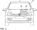
- 3 1 schematically represents a vehicle according to the invention with an internal combustion engine according to the invention.
- a combustion chamber 2 is shown inside a cylinder 13 of an Otto engine.
- a piston 14 moves within the cylinder 13 , the so-called combustion chamber roof 15 being located opposite the piston 14 .
- An inlet valve 8, an outlet valve 9, a spark plug 7 and an injector 1 protrude into the cylinder 13 and thus into the combustion chamber 2. Due to the fact that the central axis 11 of the injector 1 has an angle to the central axis 12 of the cylinder 13, it can be seen that the fuel is injected laterally at an angle into the cylinder 13. Below the roof of the combustion chamber there is a so-called snout or lower edge of the roof of the combustion chamber (a corresponding recess for installing the injector 1). During operation, the injector 1 injects jets of fuel 3 into the combustion chamber 2.
- These fuel jets 3 are created by the fuel being sprayed through corresponding holes in a hole arrangement. If this arrangement of holes is represented as a surface of a segment of a sphere, then the central axis of each hole, which corresponds, for example, to a straight line passing through the center of the corresponding sphere and through the center of the corresponding hole, forms a relationship with the central axis 11 of the Injector 1, which can be expressed by the first angle ⁇ and ⁇ by the second angle.
- the first plane is spanned by the central axis 11 of the injector 1 and by the central axis 12 of the cylinder 13 .
- the second plane is perpendicular to the first plane and includes the central axis 1 of the injector 1, so that the central axis 11 of the injector 1 lies within both the first and the second plane.
- the first angle ⁇ corresponds to an angle in the second plane and the second angle ⁇ corresponds to an angle in the first plane.
- the center axis of a hole in the hole arrangement corresponds to the center axis of that jet which is injected through this hole into the combustion chamber 2 .
- Each hole and thus each ray is defined by the first angle ⁇ and by the second angle ⁇ .
- the first angle ⁇ indicates how large the angle is between the central axis 11 of the injector 1 and the projection of the central axis of the respective hole (jet) in the second plane.
- the second angle ⁇ indicates how large the angle is between the central axis 11 of the injector 1 and the projection of the central axis of the respective hole (jet) in the first plane.
- the rays 21-25 meet the lower edge of the combustion chamber roof 15 (snout).
- the rays 21-25 are below the curve 6, which represents the course of the lower edge of the combustion chamber roof 15, which is also the case in accordance with the invention in 2 illustrated spray geometry is the case.
- the diameter of one of the beams 21-25 is 150 ⁇ m, for example.
- the vehicle 10 includes an Otto engine 30 which has an injection device 20 .
- This injection device 20 in turn comprises an injector 1 with the 5-hole arrangement 4 according to the invention.
Landscapes
- Engineering & Computer Science (AREA)
- Chemical & Material Sciences (AREA)
- Combustion & Propulsion (AREA)
- Mechanical Engineering (AREA)
- General Engineering & Computer Science (AREA)
- Fuel-Injection Apparatus (AREA)
Description
- Die vorliegende Erfindung betrifft ein Verfahren, um gezielt Kraftstoff in einen Brennraum eines Zylinders eines Verbrennungsmotors eines Fahrzeugs einzuspritzen.
- Das Einspritzen von Kraftstoff in einen Brennraum mit mehreren Strahlen ist nach dem Stand der Technik gut bekannt, siehe beispielsweise
DE 100 32 330 A1 ,DE 10 2004 041 031 A1 ,DE 10 2004 002 296 A1 ,US 7,770,556 B2 ,US 2009/064 964 A1 ,US 6 883 491 B2 oderJP 2007092633 A - Dabei wird das Einspritzen des Kraftstoffs nach dem Stand der Technik derart durchgeführt, dass die Zündkerze und die Ventile des Zylinders möglichst nicht von dem eingespritzten Kraftstoff benetzt werden (siehe insbesondere
DE 100 32 330 A1 ,DE 10 2004 041 031 A1 undDE 10 2004 002 296 A1 ). Auch das Problem der Wandbenetzung beim Einspritzen des Kraftstoffs wird in den DruckschriftenDE 10 2004 041 031 A1 und in derDE 10 2004 002 296 A1 thematisiert. - Aus der
US 2006/0207550 A1 ist ein Verbrennungsmotor bekannt, bei dem ein erster Injektor Kraftstoff in das Saugrohr und jeweils ein zweiter Injektor Kraftstoff direkt in den Brennraum eines Zylinders einspritzt. Dabei ist vorgesehen, dass der Kraftstoff dem direkt einspritzenden Injektor mit einem von der angeforderten Last abhängigen Druck zugeführt wird, was zur Ausbildung unterschiedlicher Einspritzstrahlen des Kraftstoffs führt. Bei hoher Lastanforderung und hohem Kraftstoffdruck sind die aus den zwei schlitzförmigen Injektoröffnungen des direkt einspritzenden Injektors austretenden Einspritzstrahlen jeweils von der Seite gesehen fächerförmig mit, vom Brennraumdach aus gesehen, fast strichförmiger Ausprägung, wobei die beiden Einspritzstrahlen ein "V" mit einem inneren Winkel von zwischen 40° und 50° ausbilden. Dabei liegt eine Zündkerze, wiederum vom Brennraumdach aus gesehen, zwischen den zwei Schenkeln des "V". Bei niedriger Lastanforderung und niedrigem Kraftstoffdruck weisen die Einspritzstrahlen auch vom Brennraumdach aus gesehen eine Fächerform auf, wobei diese im Bereich der Zündkerze überschneiden. Dadurch soll bei geringer Last die Zündwilligkeit des Kraftstoff-Luft-Gemisches verbessert werden. - Aus der
WO 02/02928 A1 - Aus der
US 7,770,556 B2 ist ein zum direkten Einspritzen von Kraftstoff in einen Brennraum eines Verbrennungsmotors vorgesehener Injektor bekannt, der sechs Einspritzöffnung ausbildet, die in einer Ringreihe um eine Mittellängsachse herum angeordnet sind. Dabei ist der Neigungswinkel, den die Mittellängsachsen der Einspritzöffnungen jeweils mit der Mittellängsachse des Injektors einschließen, unterschiedlich. Dabei soll der Winkel zwischen den Mittellängsachsen jeweils benachbarter Einspritzöffnungen 20° oder mehr betragen. Durch die spezifische Anordnung der Einspritzöffnungen soll ein kostengünstig herstellbarer Injektor ausgebildet werden, der bei einer Späteinspritzung in einer Warmlaufphase des Verbrennungsmotors eine Konzentration des eingespritzten Kraftstoffs im Bereich der Zündkerze gewährleisten soll, ohne dabei im Betrieb des Verbrennungsmotors nach dem Erreichen des Betriebstemperaturbereichs eine nachteilige Zylinderbenetzung mit Kraftstoff zu bewirken. - Ein Injektor, mittels dem Kraftstoff über sechs Einspritzöffnungen in einen Brennraum eines Verbrennungsmotors eingespritzt wird, ist auch aus der
US 7,418,940 B1 bekannt. - Ausgehend von diesem Stand der Technik stellt sich die vorliegende Erfindung die Aufgabe, den Kraftstoff in Form von mehreren Strahlen derart in den Brennraum einzuspritzen, dass möglichst
- keine Benetzung der Lauffläche des Zylinders auftritt,
- keine Ventilteller von in den Zylinder hineinragenden Ventilen benetzt werden,
- der Kolben nicht benetzt wird, und
- das Brennraumdach nicht benetzt wird.
- Erfindungsgemäß wird diese Aufgabe durch ein Verfahren zum Einspritzen von Kraftstoff in einen Brennraum eines Zylinders eines Verbrennungsmotors eines Fahrzeugs nach Anspruch 1 und durch einen Verbrennungsmotor nach Anspruch 5 und durch ein Fahrzeug mit dem Verbrennungsmotor nach Anspruch 7 gelöst. Die abhängigen Ansprüche definieren bevorzugte und vorteilhafte Ausführungsformen der vorliegenden Erfindung.
- Im Rahmen der vorliegenden Erfindung wird ein Verfahren zum Einspritzen von Kraftstoff in den Brennraum eines Zylinders des Verbrennungsmotors eines Fahrzeugs bereitgestellt. Dabei wird der Kraftstoff mittels eines Injektors in Form von genau fünf Strahlen in den Brennraum eingespritzt.
- Eine erste Ebene ist derart definiert, dass sowohl die Mittelachse des Injektors als auch die Mittelachse des Zylinders in dieser ersten Ebene liegen, die erste Ebene also von der Mittelachse des Injektors und der Mittelachse des Zylinders aufgespannt wird.
- Eine zweite Ebene welche senkrecht zu der ersten Ebene liegt, ist derart definiert, dass in dieser zweiten Ebene sowohl die Mittelachse des Injektors als auch die Flächennormale der ersten Ebene liegen, so dass diese zweite Ebene durch die Mittelachse des Injektors und durch die Flächennormale der ersten Ebene aufgespannt wird.
- Um eine Spraygeometrie (bestimmte Anordnung der Einspritzstrahlen) zu bestimmen, wurden zahlreiche Simulationen und Experimente durchgeführt, die zum einen die vorab definierten Aufgaben möglichst optimal erfüllen und zum anderen ein Kraftstoff-Luft-Gemisch innerhalb des Zylinders erzeugen, wobei das Volumen des Brennraums dennoch optimal ausgenutzt wird.
- Das Ergebnis der Simulationen und Experimente ist eine bestimmte Spraygeometrie mit fünf Löchern einer Lochanordnung eines Injektors.
- Um eine Spraygeometrie zu definieren, wird jeder Strahl (und damit jedes Loch der Lochanordnung des Injektors) über einen ersten Winkel und über einen zweiten Winkel definiert. Dabei liegt der erste Winkel zwischen einer Projektion der Mittelachse des jeweiligen Strahls in die zweite Ebene und der Mittelachse des Injektors. Der zweite Winkel liegt zwischen der Projektion der Mittelachse des jeweiligen Strahls in die erste Ebene und der Mittelachse des Injektors.
- Bei der Spraygeometrie mit genau fünf Löchern wird der Kraftstoff (insbesondere gleichzeitig) mit genau fünf Strahlen in den Brennraum gespritzt, so dass ein erster, ein zweiter, ein dritter, ein vierter und ein fünfter Strahl existieren. Tabelle 1 stellt nachfolgend dar, wo sich die einzelnen Strahlen der erfindungsgemäßen optimalen 5-Loch-Anordnung im Bezug zu der Mittelachse des Injektors jeweils befinden.
Tabelle 1: optimale 5-Loch-Anordnung erster Winkel (α) zweiter Winkel (β) optimal Toleranzbereich optimal Toleranzbereich 1. Strahl 0° -3° bis +3° 0° -3° bis +3° 2. Strahl -28° -40° bis -20° -28° -40° bis -20° 3. Strahl -10° -20° bis -5° -25° -40° bis -20° 4. Strahl +10° +5° bis +20° -25° -40° bis -20° 5. Strahl +28° +20° bis +40° -28° -40° bis -20° - Vorteilhafterweise gilt für jedes Strahlenpaar, dass ein Mindestwinkel zwischen den beiden Mittelachsen der zwei Strahlen des Strahlenpaars größer als 15° (besser 20°) ist.
- Es sei darauf hingewiesen, dass dieser Winkel von mehr als 15° (besser 20°) nicht auf die erste oder zweite Ebene beschränkt ist, sondern dass dieser einzuhaltende Winkel für diejenige Ebene gilt, welche von den beiden Mittelachsen der jeweiligen beiden Strahlen aufgespannt wird.
- Indem der genannte Mindestwinkel eingehalten wird, wird in vorteilhafterweise dafür gesorgt, dass zwei benachbarte Strahlen nicht derart dicht beieinander liegen, sodass sich ihre Strahlen verstärken. Würden nämlich zwei Strahlen zu dicht beieinander liegen, wäre in nachteiliger Weise eine Penetration der entsprechenden Kraftstoffstrahlen zu groß, so dass der Kraftstoff zu weit in den Brennraum gespritzt würde, so dass er beispielsweise die Zylinderlauffläche benetzen könnte.
- Gemäss einer Ausführungsform werden die Strahlen mit einem Druck von mehr als 200 bar (besser mehr als 250 bar) in den Brennraum eingespritzt. Darüber hinaus kann zum Betrieb des Verbrennungsmotors ein spezielles Einspritztiming eingesetzt werden, wobei die Einspritzstrahlen abhängig von der Kolbenstellung und der Stellung des Einlassventils (des Hubs des Einlassventils) eingespritzt werden.
- Durch den hohen Einspritzdruck von 200 bar (oder gar 250 bar) wird in vorteilhafterweise eine Benetzung des Kolbens oder des Einlassventils vermieden und auch eine Partikelemission (im Abgas) reduziert. Die vorliegende Erfindung bietet aufgrund der seitlichen Einspritzlage ebenfalls die Möglichkeit, Common-Rail-Injektoren mit Einspritzdrücken bis zu 800 bar einzusetzen, welche beispielsweise für den Dieselmotor bekannt sind.
- Darüber hinaus ist erfindungsgemäß eine Mehrfacheinspritzung möglich, was bedeutet, dass jeder der fünf Strahlen im selben Arbeitstakt mehrfach eingespritzt wird.
- Durch die Mehrfacheinspritzung werden die Verdampfung und die Gemischbildung im Zylinder weiter optimiert, wodurch insbesondere das Kaltstart- und Emissionsverhalten verbessert wird.
- Im Rahmen der vorliegenden Erfindung wird ein Kraftstoffeinspritzsystem zum Einspritzen von Kraftstoff in einen Brennraum eines Zylinders eines Verbrennungsmotors eines Fahrzeugs bereitgestellt.
- Dabei umfasst die Kraftstoffeinspritzvorrichtung einen Injektor mit einer Lochanordnung (zum Beispiel eine Fläche), welche genau fünf durch die Lochanordnung beziehungsweise Fläche hindurch verlaufende Löcher aufweist.
- Es ist vorgesehen, dass der Injektor den Kraftstoff durch die fünf Löcher der Lochanordnung hindurch in den Brennraum einspritzt. Wird durch ein Loch der Lochanordnung hindurch mittels des Injektors ein Kraftstoffstrahl in den Brennraum gespritzt, so entspricht die Mittelachse dieses Loches insbesondere der Mittelachse dieses Strahls. Daher entspricht die Richtung der Mittelachse des jeweiligen Loches der Richtung der Mittelachse des durch das Loch erzeugbaren Strahls. Die Spraygeometrie der Lochanordnung entspricht derjenigen, die bezüglich des erfindungsgemäßen Verfahrens in der Tabelle 1 angegeben ist.
- Durch die vorliegende Erfindung wird der Kraftstoff derart in den Brennraum eingespritzt, dass weder die Zylinderlauffläche noch das Brennraumdach noch der Kolben von dem eingespritzten Kraftstoff benetzt werden. Dies führt in vorteilhafterweise zu einer Reduktion der Partikelemissionen, zu einer Vermeidung von Verkokungen, zu einer Vermeidung von einer Schmierölverdünnung und zu einer Erhöhung der Brenngeschwindigkeit des sich im Brennraum bildenden Kraftstoff-Luft-Gemisches. Anders ausgedrückt ist das erfindungsgemäße Spraybild der Hochdruck-Einspritzventile (Hochdruck-Injektoren) bzw. die Anordnung der einzelnen Einspritzstrahlen so ausgelegt, dass eine Kraftstoffbenetzung der Einlassventile, des Kolbens und der Zylinderlaufbuchsen mittels spezieller Hochdruck-Einspritzventil-Auslegung und einer sehr hohen Ladungsbewegung ohne Klappensystem im Einlasskanal vermieden wird.
- Durch die vorliegende Erfindung werden die in der Nähe der Zylinderwand vorhandenen Kohlenwasserstoffe reduziert ("Wall-Quenching") und somit die Schadstoffemissionen deutlich abgesenkt. Dies resultiert nicht zuletzt aus einer deutlichen Reduktion der Penetration der Kraftstoffstrahlen. Um die Partikelemissionen weiter zu reduzieren, kann eine Kombination aus Saugrohr- und Direkteinspritzung realisiert werden. Darüber hinaus ist es möglich, den Verbrennungsmotor mit einem Einlass- und mit einem Auslassnockenwellensteller zu realisieren, um größtmögliche Überschneidungen realisieren zu können und somit das Drehmoment bei kleineren Drehzahlen ("Low End Torque") zu verbessern und den Kraftstoffverbrauch und die Schadstoffemissionen (insbesondere Partikelemissionen und Emissionen von Kohlenwasserstoffen) abzusenken. Die Erhöhung der Ladungsbewegung resultiert in einer Erhöhung der turbulenten kinetischen Energie im Zylinder des Verbrennungsmotors. Ein weiterer Vorteil der vorliegenden Erfindung ergibt sich durch die Reduzierung der Ablagerungen auf Kolben und Brennraumdach, was wiederum zur Reduzierung der Partikelemissionen beiträgt.
- Die vorliegende Erfindung ist insbesondere für einen Ottomotor eines Kraftfahrzeugs geeignet. Selbstverständlich ist die vorliegende Erfindung nicht auf diesen bevorzugten Anwendungsbereich eingeschränkt, da die vorliegende Erfindung auch bei Schiffen, Flugzeugen sowie gleisgebundenen oder spurgeführten Fahrzeugen einsetzbar ist. Darüber hinaus ist die vorliegende Erfindung zumindest prinzipiell auch bei anderen Motortypen einsetzbar.
- Im Folgenden wird die vorliegende Erfindung anhand erfindungsgemäßer Ausführungsformen mit Bezug zu den Figuren im Detail beschrieben.
- In
Fig. 1 ist das Innere eines Zylinders eines Ottomotors dargestellt. - In
Fig. 2 ist die Ausrichtung der Einspritzstrahlen eines Injektors mit erfindungsgemäßer 5-LochAnordnung dargestellt. -
Fig. 3 stellt schematisch ein erfindungsgemäßes Fahrzeug mit einem erfindungsgemäßen Verbrennungsmotor dar. - In
Fig. 1 ist ein Brennraum 2 im Inneren eines Zylinders 13 eines Ottomotors dargestellt. Innerhalb des Zylinders 13 bewegt sich ein Kolben 14, wobei sich dem Kolben 14 gegenüber das so genannte Brennraumdach 15 befindet. In den Zylinder 13 und damit in den Brennraum 2 hinein ragen ein Einlassventil 8, ein Auslassventil 9, eine Zündkerze 7 und ein Injektor 1. Anhand der Tatsache, dass die Mittelachse 11 des Injektors 1 zu der Mittelachse 12 des Zylinders 13 einen Winkel aufweist, erkennt man, dass der Kraftstoff seitlich schräg in den Zylinder 13 eingespritzt wird. Unterhalb des Brennraumdachs befindet sich eine so genannte Schnaupe bzw. Unterkante des Brennraumdaches (eine entsprechenden Aussparung zur Montage des Injektors 1). Im Betrieb spritzt der Injektor 1 Kraftstoffstrahlen 3 in den Brennraum 2. - Diese Kraftstoffstrahlen 3 entstehen, indem der Kraftstoff durch entsprechende Löcher einer Lochanordnung gespritzt wird. Stellt man sich diese Lochanordnung als eine Oberfläche eines Segments einer Kugel dar, dann bildet die Mittelachse jedes Loches, welche beispielsweise einer Geraden entspricht, die durch den Mittelpunkt der entsprechenden Kugel und durch den Mittelpunkt des entsprechenden Lochs verläuft, eine Beziehung zu der Mittelachse 11 des Injektors 1, was durch den ersten Winkel α und durch den zweiten Winkel β ausgedrückt werden kann.
- Dazu existieren eine erste und eine zweite Ebene. Die erste Ebene wird von der Mittelachse 11 des Injektors 1 und von der Mittelachse 12 des Zylinders 13 aufgespannt. Die zweite Ebene steht senkrecht auf der ersten Ebene und beinhaltet die Mittelachse 1 des Injektors 1, so dass die Mittelachse 11 des Injektors 1 sowohl innerhalb der ersten als auch innerhalb der zweiten Ebene liegt. Der erste Winkel α entspricht einem Winkel in der zweiten Ebene, und der zweite Winkel β entspricht einem Winkel in der ersten Ebene. Die Mittelachse eines Loches der Lochanordnung entspricht der Mittelachse desjenigen Strahls, welcher durch dieses Loch hindurch in den Brennraum 2 eingespritzt wird. Jedes Loch und damit jeder Strahl wird durch den ersten Winkel α und durch den zweiten Winkel β definiert. Der erste Winkel α gibt dabei an, wie groß der Winkel zwischen der Mittelachse 11 des Injektors 1 und der Projektion der Mittelachse des jeweiligen Loches (Strahls) in der zweiten Ebene ist. In ähnlicher Weise gibt der zweite Winkel β an, wie groß der Winkel zwischen der Mittelachse 11 des Injektors 1 und der Projektion der Mittelachse des jeweiligen Loches (Strahls) in der ersten Ebene ist.
- In
Fig. 2 ist die Ausrichtung der fünf Strahlen 21-25 der 5-Loch-Anordnung dargestellt. Zusätzlich ist inFig. 2 die Ventilhubkurve 5 jeweils für das Einlassventil 8 und das Ausmaßventil 9 dargestellt. Damit der jeweilige Strahl 21-25 zu keinem Zeitpunkt eines der Ventile 8, 9 (oder besser den Ventilteller eines der Ventile 8, 9) trifft, liegt der entsprechende Strahl 21-25 außerhalb der geschlossenen Ventilhubkurve 5, was bei der erfindungsgemäßen inFig. 2 dargestellten Spraygeometrie der Fall ist. - Darüber hinaus trifft keiner der Strahlen 21-25 die Unterkante des Brennraumdaches 15 (Schnaupe). Dazu liegen die Strahlen 21-25 unterhalb der Kurve 6, welche den Verlauf der Unterkante des Brennraumdaches 15 darstellt, was ebenfalls bei der erfindungsgemäßen in
Fig. 2 dargestellten Spraygeometrie der Fall ist. - Der Durchmesser eines der Strahlen 21-25 beträgt beispielsweise 150 µm.
- Schließlich ist in
Fig. 3 ein erfindungsgemäßes Fahrzeug 10 schematisch dargestellt. Das Fahrzeug 10 umfasst einen Ottomotor 30, welcher eine Einspritzvorrichtung 20 aufweist. Diese Einspritzvorrichtung 20 umfasst ihrerseits einen Injektor 1 mit der erfindungsgemäßen 5-LochAnordnung 4.
Claims (7)
- Verfahren zum Einspritzen von Kraftstoff in einen Brennraum (2) eines Zylinders (13) eines Verbrennungsmotors (30) eines Fahrzeugs (10),- wobei der Kraftstoff mit genau fünf Strahlen (3) mittels eines Injektors (1) in den Brennraum (2) eingespritzt wird,- wobei eine erste Ebene definiert ist, in welcher sowohl die Mittelachse (11) des Injektors (1) als auch die Mittelachse (12) des Zylinders (13) liegen, und- wobei eine zweite Ebene definiert ist, in welcher sowohl die Mittelachse (11) des Injektors (1) als auch die Flächennormale der ersten Ebene liegen,wobei eine Richtung jeder der Strahlen (3)• durch einen ersten Winkel (α) zwischen der Mittelachse (11) des Injektors (1) und einer Projektion der Mittelachse des jeweiligen Strahls (3) in die zweite Ebene, und• durch einen zweiten Winkel (β) zwischen der Mittelachse (11) des Injektors (1) und einer Projektion der Mittelachse des jeweiligen Strahls (3) in die erste Ebene definiert ist,- wobei die Strahlen (3) einen ersten, einen zweiten, einen dritten, einen vierten und einen fünften Strahl umfassen, wobei- der erste Winkel (α) des ersten Strahls (21) in einem Winkelbereich von -3° bis +3° liegt und- der zweite Winkel (β) des ersten Strahls (21) in einem Winkelbereich von -3° bis +3° liegt und- der erste Winkel (α) des zweiten Strahls (22) in einem Winkelbereich von -40° bis -20° liegt und- dass der zweite Winkel (β) des zweiten Strahls (22) in einem Winkelbereich von -40° bis -20° liegt und- der erste Winkel (α) des dritten Strahls (23) in einem Winkelbereich von -20° bis -5° liegt und- der zweite Winkel (β) des dritten Strahls (23) in einem Winkelbereich von -40° bis -20° liegt und- der erste Winkel (α) des vierten Strahls (24) in einem Winkelbereich von +5° bis +20° liegt und- der zweite Winkel (β) des vierten Strahls (24) in einem Winkelbereich von -40° bis -20° liegt und- der erste Winkel (α) des fünften Strahls (25) in einem Winkelbereich von +20° bis +40° liegt und- der zweite Winkel (β) des fünften Strahls (25) in einem Winkelbereich von -40° bis -20° liegt,wobei alle Strahlen (21-25) außerhalb des in die Ebenen projizierten Verlaufes einer Ventilhubkurve (5) und unterhalb des in die Ebenen projizierten Verlaufes einer Kurve (6) der Unterkante eines Brennraumdaches (15) liegen.
- Verfahren nach Anspruch 1,
dadurch gekennzeichnet,
dass die Strahlen (3) derart erzeugt werden, dass für jedes Strahlenpaar, welches aus zwei der Strahlen (3) gebildet wird, ein Winkel zwischen den beiden Mittelachsen der zwei Strahlen des Strahlenpaars größer als 15° ist. - Verfahren nach einem der vorherigen Ansprüche,
dadurch gekennzeichnet,
dass die Strahlen (3) mit einem Druck von mehr als 200 bar in den Brennraum (2) gespritzt werden. - Verfahren nach einem der vorhergehenden Ansprüche,
dadurch gekennzeichnet,
dass die Strahlen (3) in demselben Arbeitstakt mehrfach eingespritzt werden. - Verbrennungsmotor (30) eines Fahrzeugs (10) mit einem Injektor (1) zum Einspritzen von Kraftstoff in einen Brennraum (2) eines Zylinders (13) des Verbrennungsmotors (30),- wobei der Injektor (1) Kraftstoff durch genau fünf Löcher einer Lochanordnung (4) des Injektors (4) in den Brennraum (2) spritzt,- wobei eine erste Ebene definiert ist, in welcher sowohl die Mittelachse (11) des Injektors (1) als auch die Mittelachse (12) des Zylinders (13) liegen, und- wobei eine zweite Ebene definiert ist, in welcher sowohl die Mittelachse (11) des Injektors (1) als auch die Flächennormale der ersten Ebene liegen,wobei eine Richtung jeder der Strahlen (3)• durch einen ersten Winkel (α) zwischen der Mittelachse (11) des Injektors (1) und einer Projektion der Mittelachse des jeweiligen Strahls (3) in die zweite Ebene, und• durch einen zweiten Winkel (β) zwischen der Mittelachse (11) des Injektors (1) und einer Projektion der Mittelachse des jeweiligen Strahls (3) in die erste Ebene definiert ist,- wobei die Strahlen (3) einen ersten, einen zweiten, einen dritten, einen vierten und einen fünften Strahl umfassen, wobei- der erste Winkel (α) des ersten Strahls (21) in einem Winkelbereich von -3° bis +3° liegt und- der zweite Winkel (β) des ersten Strahls (21) in einem Winkelbereich von -3° bis +3° liegt und- der erste Winkel (α) des zweiten Strahls (22) in einem Winkelbereich von -40° bis -20° liegt und- dass der zweite Winkel (β) des zweiten Strahls (22) in einem Winkelbereich von -40° bis -20° liegt und- der erste Winkel (α) des dritten Strahls (23) in einem Winkelbereich von -20° bis -5° liegt und- der zweite Winkel (β) des dritten Strahls (23) in einem Winkelbereich von -40° bis -20° liegt und- der erste Winkel (α) des vierten Strahls (24) in einem Winkelbereich von +5° bis +20° liegt und- der zweite Winkel (β) des vierten Strahls (24) in einem Winkelbereich von -40° bis -20° liegt und- der erste Winkel (α) des fünften Strahls (25) in einem Winkelbereich von +20° bis +40° liegt und- der zweite Winkel (β) des fünften Strahls (25) in einem Winkelbereich von -40° bis -20° liegt,wobei alle Strahlen (21-25) außerhalb des in die Ebenen projizierten Verlaufes einer Ventilhubkurve (5) und unterhalb des in die Ebenen projizierten Verlaufes einer Kurve (6) der Unterkante eines Brennraumdaches (15) liegen.
- Verbrennungsmotor (30) nach Anspruch 5, dadurch gekennzeichnet, dass eine Richtung der Mittelachse jedes der Löcher eine Richtung der Mittelachse des durch das Loch erzeugbaren Strahls bestimmt.
- Fahrzeug (10) mit einem Verbrennungsmotor (30) nach Anspruch 5 oder Anspruch 6.
Applications Claiming Priority (3)
| Application Number | Priority Date | Filing Date | Title |
|---|---|---|---|
| DE201110018949 DE102011018949A1 (de) | 2011-04-29 | 2011-04-29 | Verfahren und Vorrichtung zum Einspritzen von Kraftstoff in einen Brennraum |
| DE102012005456 | 2012-03-20 | ||
| PCT/EP2012/001790 WO2012146378A2 (de) | 2011-04-29 | 2012-04-26 | Verfahren und vorrichtung zum einspritzen von kraftstoff in einen brennraum |
Publications (2)
| Publication Number | Publication Date |
|---|---|
| EP2702256A2 EP2702256A2 (de) | 2014-03-05 |
| EP2702256B1 true EP2702256B1 (de) | 2022-06-08 |
Family
ID=46201541
Family Applications (1)
| Application Number | Title | Priority Date | Filing Date |
|---|---|---|---|
| EP12724888.8A Active EP2702256B1 (de) | 2011-04-29 | 2012-04-26 | Verbrennungsmotor und verfahren zum einspritzen von kraftstoff in einen brennraum eines verbrennungsmotors |
Country Status (4)
| Country | Link |
|---|---|
| US (1) | US9394871B2 (de) |
| EP (1) | EP2702256B1 (de) |
| CN (1) | CN103620179B (de) |
| WO (1) | WO2012146378A2 (de) |
Families Citing this family (3)
| Publication number | Priority date | Publication date | Assignee | Title |
|---|---|---|---|---|
| EP3291972B1 (de) | 2015-05-04 | 2021-01-13 | SKL Schwergewebekonfektion Lichtenstein GmbH | Hybrider, textilverstärkter multi-material-verbundwerkstoff und verfahren zu seiner herstellung |
| CN107060883A (zh) * | 2017-03-10 | 2017-08-18 | 王明忠 | 水动力、油水三次动力(活塞式)组合动力发动机 |
| DE102017107947A1 (de) * | 2017-04-12 | 2018-10-18 | Volkswagen Ag | Strahlbild eines Mehrloch-Einspritzventils für Einspritzdrücke über 300 bar bei Ottomotoren mit zentraler Injektorlage |
Citations (3)
| Publication number | Priority date | Publication date | Assignee | Title |
|---|---|---|---|---|
| US6883491B2 (en) * | 2001-05-21 | 2005-04-26 | Robert Bosch Gmbh | Fuel injection system |
| US7418940B1 (en) * | 2007-08-30 | 2008-09-02 | Ford Global Technologies, Llc | Fuel injector spray pattern for direct injection spark ignition engines |
| US20090064964A1 (en) * | 2007-09-10 | 2009-03-12 | Gm Global Technology Operations, Inc. | Spark ignited direct injection flow geometry for improved combustion |
Family Cites Families (13)
| Publication number | Priority date | Publication date | Assignee | Title |
|---|---|---|---|---|
| DE10032336A1 (de) | 2000-07-04 | 2002-01-17 | Bosch Gmbh Robert | Brennstoffeinspritzsystem |
| DE10032330A1 (de) * | 2000-07-04 | 2002-01-17 | Bosch Gmbh Robert | Brennstoffeinspritzsystem |
| JP2003269176A (ja) | 2002-01-09 | 2003-09-25 | Nissan Motor Co Ltd | 筒内直噴エンジン |
| JP4022882B2 (ja) * | 2002-06-20 | 2007-12-19 | 株式会社デンソー | 燃料噴射装置 |
| DE102004002296B4 (de) | 2004-01-16 | 2013-10-10 | Audi Ag | Kraftstoffeinspritzung und Verfahren zur Einspritzung von Kraftstoff |
| DE102004005727A1 (de) | 2004-02-05 | 2005-09-01 | Robert Bosch Gmbh | Brennstoffeinspritzsystem |
| DE102004041031A1 (de) | 2004-08-25 | 2006-03-02 | Audi Ag | Kraftstoff-Einspritzventil mit Strahldurchdringung |
| JP4543978B2 (ja) | 2005-03-18 | 2010-09-15 | トヨタ自動車株式会社 | 内燃機関の制御装置 |
| JP2007092633A (ja) | 2005-09-28 | 2007-04-12 | Mazda Motor Corp | 火花点火式直噴エンジン |
| JP4535032B2 (ja) * | 2006-07-04 | 2010-09-01 | 株式会社デンソー | 燃料噴射制御装置 |
| JP2009024683A (ja) | 2007-07-24 | 2009-02-05 | Hitachi Ltd | 複数の噴孔を有するインジェクタ、当該インジェクタを備えた筒内ガソリン噴射型内燃機関とその制御方法 |
| US8056531B2 (en) * | 2010-06-24 | 2011-11-15 | Ford Global Technologies Llc | Shallow piston bowl and injector spray pattern for a gasoline, direct-injection engine |
| AT508578B1 (de) | 2010-10-07 | 2012-08-15 | Avl List Gmbh | Verfahren zum betreiben einer viertakt-brennkraftmaschine mit funkenzündung |
-
2012
- 2012-04-26 WO PCT/EP2012/001790 patent/WO2012146378A2/de not_active Ceased
- 2012-04-26 US US14/115,832 patent/US9394871B2/en active Active
- 2012-04-26 CN CN201280031976.4A patent/CN103620179B/zh active Active
- 2012-04-26 EP EP12724888.8A patent/EP2702256B1/de active Active
Patent Citations (3)
| Publication number | Priority date | Publication date | Assignee | Title |
|---|---|---|---|---|
| US6883491B2 (en) * | 2001-05-21 | 2005-04-26 | Robert Bosch Gmbh | Fuel injection system |
| US7418940B1 (en) * | 2007-08-30 | 2008-09-02 | Ford Global Technologies, Llc | Fuel injector spray pattern for direct injection spark ignition engines |
| US20090064964A1 (en) * | 2007-09-10 | 2009-03-12 | Gm Global Technology Operations, Inc. | Spark ignited direct injection flow geometry for improved combustion |
Also Published As
| Publication number | Publication date |
|---|---|
| EP2702256A2 (de) | 2014-03-05 |
| US9394871B2 (en) | 2016-07-19 |
| CN103620179A (zh) | 2014-03-05 |
| US20140251274A1 (en) | 2014-09-11 |
| WO2012146378A3 (de) | 2013-02-21 |
| CN103620179B (zh) | 2017-08-18 |
| WO2012146378A2 (de) | 2012-11-01 |
Similar Documents
| Publication | Publication Date | Title |
|---|---|---|
| EP1301702B1 (de) | Brennstoffeinspritzsystem | |
| DE112015004524B4 (de) | Kraftstoffeinspritzdüse mit Düse variabler Lochgröße und Sprühwinkel und MHBIB | |
| DE10012969B4 (de) | Einspritzdüse und ein Verfahren zur Bildung eines Kraftstoff-Luftgemischs | |
| DE102011015438B4 (de) | Motor mit einer durch Kraftstoffeinspritzung ausgelösten Verbrennungskammermischung | |
| DE102016117297A1 (de) | Kraftstoffeinspritzvorrichtung | |
| EP1290321A1 (de) | Brennstoffeinspritzsystem und verfahren zum einspritzen | |
| DE102009042155A1 (de) | Kraftstoff-Einspritzventil für eine Brennkraftmaschine | |
| EP1319822B1 (de) | Brennkraftmaschine mit Direkteinspritzung | |
| EP2776702B1 (de) | Einspritzdüse | |
| EP1290322B1 (de) | Brennstoffeinspritzsystem | |
| DE102016118591A1 (de) | Benzin-diesel-kombinations-verbrennungsmotor | |
| EP1408231B1 (de) | Einspritzvorrichtung zum Einspritzen von Kraftstoff | |
| WO2012146378A2 (de) | Verfahren und vorrichtung zum einspritzen von kraftstoff in einen brennraum | |
| WO2020038702A1 (de) | Verfahren zum betreiben einer verbrennungskraftmaschine für ein kraftfahrzeug, sowie verbrennungskraftmaschine für ein kraftfahrzeug | |
| DE102018133550B4 (de) | Verbrennungskraftmaschine | |
| DE10122352B4 (de) | Brennstoffeinspritzsystem | |
| DE102009018485A1 (de) | Verbrennungskraftmaschine | |
| EP2898214B1 (de) | Kraftstoff-einspritzsystem einer brennkraftmaschine | |
| EP1413745B1 (de) | Kraftstoffinjektor und Brennkraftmaschine mit Direkteinspritzung | |
| EP1481159B1 (de) | Brennstoffeinspritzventil | |
| DE102004002296B4 (de) | Kraftstoffeinspritzung und Verfahren zur Einspritzung von Kraftstoff | |
| DE102011018949A1 (de) | Verfahren und Vorrichtung zum Einspritzen von Kraftstoff in einen Brennraum | |
| DE10106887A1 (de) | Direkteinspritzende Brennkraftmaschine mit Fremdzündung und Verfahren zum Betrieb einer derartigen Brennkraftmaschine | |
| DE102018003529A1 (de) | Iniektoranordnung eines Injektors einer Verbrennungskraftmaschine | |
| WO2006048129A1 (de) | Brennkraftmaschine |
Legal Events
| Date | Code | Title | Description |
|---|---|---|---|
| PUAI | Public reference made under article 153(3) epc to a published international application that has entered the european phase |
Free format text: ORIGINAL CODE: 0009012 |
|
| 17P | Request for examination filed |
Effective date: 20131129 |
|
| AK | Designated contracting states |
Kind code of ref document: A2 Designated state(s): AL AT BE BG CH CY CZ DE DK EE ES FI FR GB GR HR HU IE IS IT LI LT LU LV MC MK MT NL NO PL PT RO RS SE SI SK SM TR |
|
| RIN1 | Information on inventor provided before grant (corrected) |
Inventor name: EBUS, FEITSE Inventor name: HENTSCHEL, LARS Inventor name: SCHINTZEL, KAY Inventor name: THEOBALD, JOERG Inventor name: THAYSEN, ANDREAS |
|
| DAX | Request for extension of the european patent (deleted) | ||
| STAA | Information on the status of an ep patent application or granted ep patent |
Free format text: STATUS: EXAMINATION IS IN PROGRESS |
|
| 17Q | First examination report despatched |
Effective date: 20170203 |
|
| GRAP | Despatch of communication of intention to grant a patent |
Free format text: ORIGINAL CODE: EPIDOSNIGR1 |
|
| STAA | Information on the status of an ep patent application or granted ep patent |
Free format text: STATUS: GRANT OF PATENT IS INTENDED |
|
| RIC1 | Information provided on ipc code assigned before grant |
Ipc: F02B 23/10 20060101AFI20211122BHEP |
|
| INTG | Intention to grant announced |
Effective date: 20211221 |
|
| GRAS | Grant fee paid |
Free format text: ORIGINAL CODE: EPIDOSNIGR3 |
|
| GRAA | (expected) grant |
Free format text: ORIGINAL CODE: 0009210 |
|
| STAA | Information on the status of an ep patent application or granted ep patent |
Free format text: STATUS: THE PATENT HAS BEEN GRANTED |
|
| AK | Designated contracting states |
Kind code of ref document: B1 Designated state(s): AL AT BE BG CH CY CZ DE DK EE ES FI FR GB GR HR HU IE IS IT LI LT LU LV MC MK MT NL NO PL PT RO RS SE SI SK SM TR |
|
| REG | Reference to a national code |
Ref country code: GB Ref legal event code: FG4D Free format text: NOT ENGLISH |
|
| REG | Reference to a national code |
Ref country code: AT Ref legal event code: REF Ref document number: 1497061 Country of ref document: AT Kind code of ref document: T Effective date: 20220615 Ref country code: CH Ref legal event code: EP |
|
| REG | Reference to a national code |
Ref country code: DE Ref legal event code: R096 Ref document number: 502012017057 Country of ref document: DE |
|
| REG | Reference to a national code |
Ref country code: IE Ref legal event code: FG4D Free format text: LANGUAGE OF EP DOCUMENT: GERMAN |
|
| REG | Reference to a national code |
Ref country code: LT Ref legal event code: MG9D |
|
| REG | Reference to a national code |
Ref country code: NL Ref legal event code: MP Effective date: 20220608 |
|
| PG25 | Lapsed in a contracting state [announced via postgrant information from national office to epo] |
Ref country code: SE Free format text: LAPSE BECAUSE OF FAILURE TO SUBMIT A TRANSLATION OF THE DESCRIPTION OR TO PAY THE FEE WITHIN THE PRESCRIBED TIME-LIMIT Effective date: 20220608 Ref country code: NO Free format text: LAPSE BECAUSE OF FAILURE TO SUBMIT A TRANSLATION OF THE DESCRIPTION OR TO PAY THE FEE WITHIN THE PRESCRIBED TIME-LIMIT Effective date: 20220908 Ref country code: LT Free format text: LAPSE BECAUSE OF FAILURE TO SUBMIT A TRANSLATION OF THE DESCRIPTION OR TO PAY THE FEE WITHIN THE PRESCRIBED TIME-LIMIT Effective date: 20220608 Ref country code: HR Free format text: LAPSE BECAUSE OF FAILURE TO SUBMIT A TRANSLATION OF THE DESCRIPTION OR TO PAY THE FEE WITHIN THE PRESCRIBED TIME-LIMIT Effective date: 20220608 Ref country code: GR Free format text: LAPSE BECAUSE OF FAILURE TO SUBMIT A TRANSLATION OF THE DESCRIPTION OR TO PAY THE FEE WITHIN THE PRESCRIBED TIME-LIMIT Effective date: 20220909 Ref country code: FI Free format text: LAPSE BECAUSE OF FAILURE TO SUBMIT A TRANSLATION OF THE DESCRIPTION OR TO PAY THE FEE WITHIN THE PRESCRIBED TIME-LIMIT Effective date: 20220608 Ref country code: ES Free format text: LAPSE BECAUSE OF FAILURE TO SUBMIT A TRANSLATION OF THE DESCRIPTION OR TO PAY THE FEE WITHIN THE PRESCRIBED TIME-LIMIT Effective date: 20220608 Ref country code: BG Free format text: LAPSE BECAUSE OF FAILURE TO SUBMIT A TRANSLATION OF THE DESCRIPTION OR TO PAY THE FEE WITHIN THE PRESCRIBED TIME-LIMIT Effective date: 20220908 |
|
| PG25 | Lapsed in a contracting state [announced via postgrant information from national office to epo] |
Ref country code: RS Free format text: LAPSE BECAUSE OF FAILURE TO SUBMIT A TRANSLATION OF THE DESCRIPTION OR TO PAY THE FEE WITHIN THE PRESCRIBED TIME-LIMIT Effective date: 20220608 Ref country code: LV Free format text: LAPSE BECAUSE OF FAILURE TO SUBMIT A TRANSLATION OF THE DESCRIPTION OR TO PAY THE FEE WITHIN THE PRESCRIBED TIME-LIMIT Effective date: 20220608 |
|
| PG25 | Lapsed in a contracting state [announced via postgrant information from national office to epo] |
Ref country code: NL Free format text: LAPSE BECAUSE OF FAILURE TO SUBMIT A TRANSLATION OF THE DESCRIPTION OR TO PAY THE FEE WITHIN THE PRESCRIBED TIME-LIMIT Effective date: 20220608 |
|
| PG25 | Lapsed in a contracting state [announced via postgrant information from national office to epo] |
Ref country code: SM Free format text: LAPSE BECAUSE OF FAILURE TO SUBMIT A TRANSLATION OF THE DESCRIPTION OR TO PAY THE FEE WITHIN THE PRESCRIBED TIME-LIMIT Effective date: 20220608 Ref country code: SK Free format text: LAPSE BECAUSE OF FAILURE TO SUBMIT A TRANSLATION OF THE DESCRIPTION OR TO PAY THE FEE WITHIN THE PRESCRIBED TIME-LIMIT Effective date: 20220608 Ref country code: RO Free format text: LAPSE BECAUSE OF FAILURE TO SUBMIT A TRANSLATION OF THE DESCRIPTION OR TO PAY THE FEE WITHIN THE PRESCRIBED TIME-LIMIT Effective date: 20220608 Ref country code: PT Free format text: LAPSE BECAUSE OF FAILURE TO SUBMIT A TRANSLATION OF THE DESCRIPTION OR TO PAY THE FEE WITHIN THE PRESCRIBED TIME-LIMIT Effective date: 20221010 Ref country code: EE Free format text: LAPSE BECAUSE OF FAILURE TO SUBMIT A TRANSLATION OF THE DESCRIPTION OR TO PAY THE FEE WITHIN THE PRESCRIBED TIME-LIMIT Effective date: 20220608 Ref country code: CZ Free format text: LAPSE BECAUSE OF FAILURE TO SUBMIT A TRANSLATION OF THE DESCRIPTION OR TO PAY THE FEE WITHIN THE PRESCRIBED TIME-LIMIT Effective date: 20220608 |
|
| PG25 | Lapsed in a contracting state [announced via postgrant information from national office to epo] |
Ref country code: PL Free format text: LAPSE BECAUSE OF FAILURE TO SUBMIT A TRANSLATION OF THE DESCRIPTION OR TO PAY THE FEE WITHIN THE PRESCRIBED TIME-LIMIT Effective date: 20220608 Ref country code: IS Free format text: LAPSE BECAUSE OF FAILURE TO SUBMIT A TRANSLATION OF THE DESCRIPTION OR TO PAY THE FEE WITHIN THE PRESCRIBED TIME-LIMIT Effective date: 20221008 |
|
| REG | Reference to a national code |
Ref country code: DE Ref legal event code: R097 Ref document number: 502012017057 Country of ref document: DE |
|
| PG25 | Lapsed in a contracting state [announced via postgrant information from national office to epo] |
Ref country code: AL Free format text: LAPSE BECAUSE OF FAILURE TO SUBMIT A TRANSLATION OF THE DESCRIPTION OR TO PAY THE FEE WITHIN THE PRESCRIBED TIME-LIMIT Effective date: 20220608 |
|
| PLBE | No opposition filed within time limit |
Free format text: ORIGINAL CODE: 0009261 |
|
| STAA | Information on the status of an ep patent application or granted ep patent |
Free format text: STATUS: NO OPPOSITION FILED WITHIN TIME LIMIT |
|
| REG | Reference to a national code |
Ref country code: DE Ref legal event code: R082 Ref document number: 502012017057 Country of ref document: DE |
|
| PG25 | Lapsed in a contracting state [announced via postgrant information from national office to epo] |
Ref country code: DK Free format text: LAPSE BECAUSE OF FAILURE TO SUBMIT A TRANSLATION OF THE DESCRIPTION OR TO PAY THE FEE WITHIN THE PRESCRIBED TIME-LIMIT Effective date: 20220608 |
|
| 26N | No opposition filed |
Effective date: 20230310 |
|
| PG25 | Lapsed in a contracting state [announced via postgrant information from national office to epo] |
Ref country code: SI Free format text: LAPSE BECAUSE OF FAILURE TO SUBMIT A TRANSLATION OF THE DESCRIPTION OR TO PAY THE FEE WITHIN THE PRESCRIBED TIME-LIMIT Effective date: 20220608 |
|
| P01 | Opt-out of the competence of the unified patent court (upc) registered |
Effective date: 20230523 |
|
| REG | Reference to a national code |
Ref country code: CH Ref legal event code: PL |
|
| PG25 | Lapsed in a contracting state [announced via postgrant information from national office to epo] |
Ref country code: LU Free format text: LAPSE BECAUSE OF NON-PAYMENT OF DUE FEES Effective date: 20230426 |
|
| REG | Reference to a national code |
Ref country code: BE Ref legal event code: MM Effective date: 20230430 |
|
| PG25 | Lapsed in a contracting state [announced via postgrant information from national office to epo] |
Ref country code: MC Free format text: LAPSE BECAUSE OF FAILURE TO SUBMIT A TRANSLATION OF THE DESCRIPTION OR TO PAY THE FEE WITHIN THE PRESCRIBED TIME-LIMIT Effective date: 20220608 |
|
| PG25 | Lapsed in a contracting state [announced via postgrant information from national office to epo] |
Ref country code: MC Free format text: LAPSE BECAUSE OF FAILURE TO SUBMIT A TRANSLATION OF THE DESCRIPTION OR TO PAY THE FEE WITHIN THE PRESCRIBED TIME-LIMIT Effective date: 20220608 Ref country code: LI Free format text: LAPSE BECAUSE OF NON-PAYMENT OF DUE FEES Effective date: 20230430 Ref country code: IT Free format text: LAPSE BECAUSE OF FAILURE TO SUBMIT A TRANSLATION OF THE DESCRIPTION OR TO PAY THE FEE WITHIN THE PRESCRIBED TIME-LIMIT Effective date: 20220608 Ref country code: CH Free format text: LAPSE BECAUSE OF NON-PAYMENT OF DUE FEES Effective date: 20230430 |
|
| REG | Reference to a national code |
Ref country code: IE Ref legal event code: MM4A |
|
| PG25 | Lapsed in a contracting state [announced via postgrant information from national office to epo] |
Ref country code: BE Free format text: LAPSE BECAUSE OF NON-PAYMENT OF DUE FEES Effective date: 20230430 |
|
| PG25 | Lapsed in a contracting state [announced via postgrant information from national office to epo] |
Ref country code: IE Free format text: LAPSE BECAUSE OF NON-PAYMENT OF DUE FEES Effective date: 20230426 |
|
| PG25 | Lapsed in a contracting state [announced via postgrant information from national office to epo] |
Ref country code: IE Free format text: LAPSE BECAUSE OF NON-PAYMENT OF DUE FEES Effective date: 20230426 |
|
| REG | Reference to a national code |
Ref country code: AT Ref legal event code: MM01 Ref document number: 1497061 Country of ref document: AT Kind code of ref document: T Effective date: 20230426 |
|
| PG25 | Lapsed in a contracting state [announced via postgrant information from national office to epo] |
Ref country code: AT Free format text: LAPSE BECAUSE OF NON-PAYMENT OF DUE FEES Effective date: 20230426 |
|
| PG25 | Lapsed in a contracting state [announced via postgrant information from national office to epo] |
Ref country code: AT Free format text: LAPSE BECAUSE OF NON-PAYMENT OF DUE FEES Effective date: 20230426 |
|
| PG25 | Lapsed in a contracting state [announced via postgrant information from national office to epo] |
Ref country code: BG Free format text: LAPSE BECAUSE OF FAILURE TO SUBMIT A TRANSLATION OF THE DESCRIPTION OR TO PAY THE FEE WITHIN THE PRESCRIBED TIME-LIMIT Effective date: 20220608 |
|
| PG25 | Lapsed in a contracting state [announced via postgrant information from national office to epo] |
Ref country code: BG Free format text: LAPSE BECAUSE OF FAILURE TO SUBMIT A TRANSLATION OF THE DESCRIPTION OR TO PAY THE FEE WITHIN THE PRESCRIBED TIME-LIMIT Effective date: 20220608 |
|
| PG25 | Lapsed in a contracting state [announced via postgrant information from national office to epo] |
Ref country code: CY Free format text: LAPSE BECAUSE OF FAILURE TO SUBMIT A TRANSLATION OF THE DESCRIPTION OR TO PAY THE FEE WITHIN THE PRESCRIBED TIME-LIMIT; INVALID AB INITIO Effective date: 20120426 |
|
| PG25 | Lapsed in a contracting state [announced via postgrant information from national office to epo] |
Ref country code: HU Free format text: LAPSE BECAUSE OF FAILURE TO SUBMIT A TRANSLATION OF THE DESCRIPTION OR TO PAY THE FEE WITHIN THE PRESCRIBED TIME-LIMIT; INVALID AB INITIO Effective date: 20120426 |
|
| PG25 | Lapsed in a contracting state [announced via postgrant information from national office to epo] |
Ref country code: TR Free format text: LAPSE BECAUSE OF FAILURE TO SUBMIT A TRANSLATION OF THE DESCRIPTION OR TO PAY THE FEE WITHIN THE PRESCRIBED TIME-LIMIT Effective date: 20220608 |
|
| PGFP | Annual fee paid to national office [announced via postgrant information from national office to epo] |
Ref country code: GB Payment date: 20260421 Year of fee payment: 15 |
|
| PGFP | Annual fee paid to national office [announced via postgrant information from national office to epo] |
Ref country code: DE Payment date: 20260430 Year of fee payment: 15 |
|
| PGFP | Annual fee paid to national office [announced via postgrant information from national office to epo] |
Ref country code: FR Payment date: 20260423 Year of fee payment: 15 |