EP2702665B1 - Système et procédé pour suivre et archiver des données de performance de batterie - Google Patents
Système et procédé pour suivre et archiver des données de performance de batterie Download PDFInfo
- Publication number
- EP2702665B1 EP2702665B1 EP12776802.6A EP12776802A EP2702665B1 EP 2702665 B1 EP2702665 B1 EP 2702665B1 EP 12776802 A EP12776802 A EP 12776802A EP 2702665 B1 EP2702665 B1 EP 2702665B1
- Authority
- EP
- European Patent Office
- Prior art keywords
- battery
- battery pack
- processor
- data
- memory
- Prior art date
- Legal status (The legal status is an assumption and is not a legal conclusion. Google has not performed a legal analysis and makes no representation as to the accuracy of the status listed.)
- Active
Links
Images




Classifications
-
- H—ELECTRICITY
- H02—GENERATION; CONVERSION OR DISTRIBUTION OF ELECTRIC POWER
- H02J—ELECTRIC POWER NETWORKS; CIRCUIT ARRANGEMENTS OR SYSTEMS FOR SUPPLYING OR DISTRIBUTING ELECTRIC POWER; SYSTEMS FOR STORING ELECTRIC ENERGY
- H02J7/00—Circuit arrangements for charging or discharging batteries or for supplying loads from batteries
- H02J7/50—Circuit arrangements for charging or discharging batteries or for supplying loads from batteries acting upon multiple batteries simultaneously or sequentially
- H02J7/52—Circuit arrangements for charging or discharging batteries or for supplying loads from batteries acting upon multiple batteries simultaneously or sequentially for charge balancing, e.g. equalisation of charge between batteries
-
- A—HUMAN NECESSITIES
- A61—MEDICAL OR VETERINARY SCIENCE; HYGIENE
- A61H—PHYSICAL THERAPY APPARATUS, e.g. DEVICES FOR LOCATING OR STIMULATING REFLEX POINTS IN THE BODY; ARTIFICIAL RESPIRATION; MASSAGE; BATHING DEVICES FOR SPECIAL THERAPEUTIC OR HYGIENIC PURPOSES OR SPECIFIC PARTS OF THE BODY
- A61H31/00—Artificial respiration by a force applied to the chest; Heart stimulation, e.g. heart massage
- A61H31/004—Heart stimulation
-
- H—ELECTRICITY
- H02—GENERATION; CONVERSION OR DISTRIBUTION OF ELECTRIC POWER
- H02J—ELECTRIC POWER NETWORKS; CIRCUIT ARRANGEMENTS OR SYSTEMS FOR SUPPLYING OR DISTRIBUTING ELECTRIC POWER; SYSTEMS FOR STORING ELECTRIC ENERGY
- H02J7/00—Circuit arrangements for charging or discharging batteries or for supplying loads from batteries
-
- H—ELECTRICITY
- H02—GENERATION; CONVERSION OR DISTRIBUTION OF ELECTRIC POWER
- H02J—ELECTRIC POWER NETWORKS; CIRCUIT ARRANGEMENTS OR SYSTEMS FOR SUPPLYING OR DISTRIBUTING ELECTRIC POWER; SYSTEMS FOR STORING ELECTRIC ENERGY
- H02J7/00—Circuit arrangements for charging or discharging batteries or for supplying loads from batteries
- H02J7/40—Circuit arrangements for charging or discharging batteries or for supplying loads from batteries characterised by the exchange of charge or discharge related data
- H02J7/44—Circuit arrangements for charging or discharging batteries or for supplying loads from batteries characterised by the exchange of charge or discharge related data between battery management systems and power sources
-
- H—ELECTRICITY
- H02—GENERATION; CONVERSION OR DISTRIBUTION OF ELECTRIC POWER
- H02J—ELECTRIC POWER NETWORKS; CIRCUIT ARRANGEMENTS OR SYSTEMS FOR SUPPLYING OR DISTRIBUTING ELECTRIC POWER; SYSTEMS FOR STORING ELECTRIC ENERGY
- H02J7/00—Circuit arrangements for charging or discharging batteries or for supplying loads from batteries
- H02J7/40—Circuit arrangements for charging or discharging batteries or for supplying loads from batteries characterised by the exchange of charge or discharge related data
- H02J7/47—Arrangements for checking compatibility or authentication between one component, e.g. a battery or a battery charger, and another component, e.g. a power source
-
- H—ELECTRICITY
- H02—GENERATION; CONVERSION OR DISTRIBUTION OF ELECTRIC POWER
- H02J—ELECTRIC POWER NETWORKS; CIRCUIT ARRANGEMENTS OR SYSTEMS FOR SUPPLYING OR DISTRIBUTING ELECTRIC POWER; SYSTEMS FOR STORING ELECTRIC ENERGY
- H02J7/00—Circuit arrangements for charging or discharging batteries or for supplying loads from batteries
- H02J7/50—Circuit arrangements for charging or discharging batteries or for supplying loads from batteries acting upon multiple batteries simultaneously or sequentially
- H02J7/575—Parallel/serial switching of connection of batteries to charge or load circuit
-
- H—ELECTRICITY
- H02—GENERATION; CONVERSION OR DISTRIBUTION OF ELECTRIC POWER
- H02J—ELECTRIC POWER NETWORKS; CIRCUIT ARRANGEMENTS OR SYSTEMS FOR SUPPLYING OR DISTRIBUTING ELECTRIC POWER; SYSTEMS FOR STORING ELECTRIC ENERGY
- H02J7/00—Circuit arrangements for charging or discharging batteries or for supplying loads from batteries
- H02J7/60—Circuit arrangements for charging or discharging batteries or for supplying loads from batteries including safety or protection arrangements
- H02J7/61—Circuit arrangements for charging or discharging batteries or for supplying loads from batteries including safety or protection arrangements against overcharge
-
- H—ELECTRICITY
- H02—GENERATION; CONVERSION OR DISTRIBUTION OF ELECTRIC POWER
- H02J—ELECTRIC POWER NETWORKS; CIRCUIT ARRANGEMENTS OR SYSTEMS FOR SUPPLYING OR DISTRIBUTING ELECTRIC POWER; SYSTEMS FOR STORING ELECTRIC ENERGY
- H02J7/00—Circuit arrangements for charging or discharging batteries or for supplying loads from batteries
- H02J7/70—Circuit arrangements for charging or discharging batteries or for supplying loads from batteries characterised by the mechanical construction
- H02J7/751—Circuit arrangements for charging or discharging batteries or for supplying loads from batteries characterised by the mechanical construction concerning the insertion or the connection of the batteries
-
- H—ELECTRICITY
- H02—GENERATION; CONVERSION OR DISTRIBUTION OF ELECTRIC POWER
- H02J—ELECTRIC POWER NETWORKS; CIRCUIT ARRANGEMENTS OR SYSTEMS FOR SUPPLYING OR DISTRIBUTING ELECTRIC POWER; SYSTEMS FOR STORING ELECTRIC ENERGY
- H02J7/00—Circuit arrangements for charging or discharging batteries or for supplying loads from batteries
- H02J7/80—Circuit arrangements for charging or discharging batteries or for supplying loads from batteries including monitoring or indicating arrangements
- H02J7/82—Control of state of charge [SOC]
-
- H—ELECTRICITY
- H02—GENERATION; CONVERSION OR DISTRIBUTION OF ELECTRIC POWER
- H02J—ELECTRIC POWER NETWORKS; CIRCUIT ARRANGEMENTS OR SYSTEMS FOR SUPPLYING OR DISTRIBUTING ELECTRIC POWER; SYSTEMS FOR STORING ELECTRIC ENERGY
- H02J2105/00—Networks for supplying or distributing electric power characterised by their spatial reach or by the load
- H02J2105/40—Networks for supplying or distributing electric power characterised by their spatial reach or by the load characterised by the loads connecting to the networks or being supplied by the networks
- H02J2105/46—Medical devices, medical implants or life supporting devices
-
- H—ELECTRICITY
- H02—GENERATION; CONVERSION OR DISTRIBUTION OF ELECTRIC POWER
- H02J—ELECTRIC POWER NETWORKS; CIRCUIT ARRANGEMENTS OR SYSTEMS FOR SUPPLYING OR DISTRIBUTING ELECTRIC POWER; SYSTEMS FOR STORING ELECTRIC ENERGY
- H02J7/00—Circuit arrangements for charging or discharging batteries or for supplying loads from batteries
- H02J7/40—Circuit arrangements for charging or discharging batteries or for supplying loads from batteries characterised by the exchange of charge or discharge related data
- H02J7/42—Circuit arrangements for charging or discharging batteries or for supplying loads from batteries characterised by the exchange of charge or discharge related data with electronic devices having internal batteries, e.g. mobile phones
-
- H—ELECTRICITY
- H02—GENERATION; CONVERSION OR DISTRIBUTION OF ELECTRIC POWER
- H02J—ELECTRIC POWER NETWORKS; CIRCUIT ARRANGEMENTS OR SYSTEMS FOR SUPPLYING OR DISTRIBUTING ELECTRIC POWER; SYSTEMS FOR STORING ELECTRIC ENERGY
- H02J7/00—Circuit arrangements for charging or discharging batteries or for supplying loads from batteries
- H02J7/40—Circuit arrangements for charging or discharging batteries or for supplying loads from batteries characterised by the exchange of charge or discharge related data
- H02J7/443—Circuit arrangements for charging or discharging batteries or for supplying loads from batteries characterised by the exchange of charge or discharge related data using passive battery identification means, e.g. resistors or capacitors
-
- H—ELECTRICITY
- H02—GENERATION; CONVERSION OR DISTRIBUTION OF ELECTRIC POWER
- H02J—ELECTRIC POWER NETWORKS; CIRCUIT ARRANGEMENTS OR SYSTEMS FOR SUPPLYING OR DISTRIBUTING ELECTRIC POWER; SYSTEMS FOR STORING ELECTRIC ENERGY
- H02J7/00—Circuit arrangements for charging or discharging batteries or for supplying loads from batteries
- H02J7/60—Circuit arrangements for charging or discharging batteries or for supplying loads from batteries including safety or protection arrangements
- H02J7/62—Circuit arrangements for charging or discharging batteries or for supplying loads from batteries including safety or protection arrangements against overcurrent
-
- H—ELECTRICITY
- H02—GENERATION; CONVERSION OR DISTRIBUTION OF ELECTRIC POWER
- H02J—ELECTRIC POWER NETWORKS; CIRCUIT ARRANGEMENTS OR SYSTEMS FOR SUPPLYING OR DISTRIBUTING ELECTRIC POWER; SYSTEMS FOR STORING ELECTRIC ENERGY
- H02J7/00—Circuit arrangements for charging or discharging batteries or for supplying loads from batteries
- H02J7/60—Circuit arrangements for charging or discharging batteries or for supplying loads from batteries including safety or protection arrangements
- H02J7/63—Circuit arrangements for charging or discharging batteries or for supplying loads from batteries including safety or protection arrangements against overdischarge
-
- H—ELECTRICITY
- H02—GENERATION; CONVERSION OR DISTRIBUTION OF ELECTRIC POWER
- H02J—ELECTRIC POWER NETWORKS; CIRCUIT ARRANGEMENTS OR SYSTEMS FOR SUPPLYING OR DISTRIBUTING ELECTRIC POWER; SYSTEMS FOR STORING ELECTRIC ENERGY
- H02J7/00—Circuit arrangements for charging or discharging batteries or for supplying loads from batteries
- H02J7/60—Circuit arrangements for charging or discharging batteries or for supplying loads from batteries including safety or protection arrangements
- H02J7/64—Circuit arrangements for charging or discharging batteries or for supplying loads from batteries including safety or protection arrangements against overvoltage
-
- H—ELECTRICITY
- H02—GENERATION; CONVERSION OR DISTRIBUTION OF ELECTRIC POWER
- H02J—ELECTRIC POWER NETWORKS; CIRCUIT ARRANGEMENTS OR SYSTEMS FOR SUPPLYING OR DISTRIBUTING ELECTRIC POWER; SYSTEMS FOR STORING ELECTRIC ENERGY
- H02J7/00—Circuit arrangements for charging or discharging batteries or for supplying loads from batteries
- H02J7/60—Circuit arrangements for charging or discharging batteries or for supplying loads from batteries including safety or protection arrangements
- H02J7/65—Circuit arrangements for charging or discharging batteries or for supplying loads from batteries including safety or protection arrangements against overtemperature
-
- H—ELECTRICITY
- H02—GENERATION; CONVERSION OR DISTRIBUTION OF ELECTRIC POWER
- H02J—ELECTRIC POWER NETWORKS; CIRCUIT ARRANGEMENTS OR SYSTEMS FOR SUPPLYING OR DISTRIBUTING ELECTRIC POWER; SYSTEMS FOR STORING ELECTRIC ENERGY
- H02J7/00—Circuit arrangements for charging or discharging batteries or for supplying loads from batteries
- H02J7/80—Circuit arrangements for charging or discharging batteries or for supplying loads from batteries including monitoring or indicating arrangements
- H02J7/82—Control of state of charge [SOC]
- H02J7/825—Detection of fully charged condition
-
- Y—GENERAL TAGGING OF NEW TECHNOLOGICAL DEVELOPMENTS; GENERAL TAGGING OF CROSS-SECTIONAL TECHNOLOGIES SPANNING OVER SEVERAL SECTIONS OF THE IPC; TECHNICAL SUBJECTS COVERED BY FORMER USPC CROSS-REFERENCE ART COLLECTIONS [XRACs] AND DIGESTS
- Y02—TECHNOLOGIES OR APPLICATIONS FOR MITIGATION OR ADAPTATION AGAINST CLIMATE CHANGE
- Y02E—REDUCTION OF GREENHOUSE GAS [GHG] EMISSIONS, RELATED TO ENERGY GENERATION, TRANSMISSION OR DISTRIBUTION
- Y02E60/00—Enabling technologies; Technologies with a potential or indirect contribution to GHG emissions mitigation
- Y02E60/10—Energy storage using batteries
Definitions
- the invention is directed to a battery pack for providing power to a device. More specifically, the invention is directed a battery pack and battery management system having a memory in which can be stored data related to the performance of the battery.
- the memory is accessible to both internal and external processors for retrieval and analysis of the data.
- Cardiopulmonary resuscitation is a well-known and valuable method of first aid used to resuscitate people who have suffered from cardiac arrest.
- CPR requires repetitive chest compressions to squeeze the heart and the thoracic cavity to pump blood through the body.
- Artificial respiration such as mouth-to-mouth breathing or a bag mask apparatus, is used to supply air to the lungs.
- a first aid provider performs manual chest compression effectively, blood flow in the body is about 25% to 30% of normal blood flow.
- Even experienced paramedics cannot maintain adequate chest compressions for more than a few minutes. Hightower, et al., Decay In Quality Of Chest Compressions Over Time, 26 Ann. Emerg. Med. 300 (September 1995 ).
- CPR is not often successful at sustaining or reviving the patient. Nevertheless, if chest compressions could be adequately maintained, then cardiac arrest victims could be sustained for extended periods of time. Occasional reports of extended CPR efforts (45 to 90 minutes) have been reported, with the victims eventually being saved by coronary bypass surgery. See Tovar, et al., Successful Myocardial Revascularization and Neurologic Recovery, 22 Texas Heart J. 271 (1995 ).
- any CPR device should be easy to use and facilitate rapid deployment of the device on the patient.
- Our own devices are easy to deploy quickly and may significantly increase the patient's chances of survival.
- the power supply must be capable of delivering sufficient energy to the motor driving the compression device for at least that length of time.
- the power supply must be relatively light weight, so as to enhance portability of the chest compression device, yet it must deliver its power for an extended period of time without significant voltage or current drop off to ensure consistency of compression throughout the treatment period.
- the invention provides a high-performance battery pack capable of reliably providing high power and current to power a device for a prolonged period of time.
- the battery pack includes a battery management system that monitors and controls all aspects of battery operation, including charging and discharging of the battery.
- the battery management system is also capable of recording events that occur during the lifetime of the battery pack, and communicating those events for later analysis.
- the battery management system is also capable of being updated with enhanced or improved operating parameters, and is capable of managing various battery chemistries to provide for forward and backwards compatibility.
- the battery management system of the present invention includes one or more processors for monitoring and controlling the various functions of the battery management system.
- the one or more processors are configured to communicate with internal and/or external memory storage or devices to provide for storage of events that occur during the lifetime of the battery pack.
- the processors may be configured to communicate not only with internal or external storage media or devices, but may also be configured to communicate over a network with other processors, storage media or devices, or even other batteries or battery chargers.
- the network may be either wired or wireless.
- the battery management system of the present invention includes a memory in which can be stored data and information related to the performance of the battery.
- the battery management system may also include a position locating system, such as, for example, a system based on global positioning satellite (GPS) technology, and the memory may be configured to store data and information related to the location of the battery.
- the sensor may be an accelerometer for sensing how the battery is handled during use, storage and transport, and the memory is configured to store information related to the handling of the battery so that the information and data may be retrieved and analyzed.
- the present invention may include a battery that has a memory that is used as a carrier to provide for the viral, or rapid, distribution of data, operating parameters and/or software updates to other batteries or the equipment that is powered by the batteries.
- the battery obtains updated data, operating parameters and/or software from the memory of a battery charger that is used to recharge a discharged battery.
- the recharged battery carries the updated data, operating parameters and/or software to a piece of equipment that utilizes the battery for power, and, once connected to the equipment, provides for distribution of the updated data, operating parameters and software to a memory and/or processor of the equipment.
- the battery checks the memory of the charger or charging circuit, or the memory of the equipment or discharging circuit, to determine the relative date of data, operating parameters and/or software on both the battery and the equipment, and either provides updated data, operating parameters and/or software to the equipment, or retrieves later data, operating parameters and/or software from the equipment to update the memory of the battery and/or further distribute the updated data, operating parameters and/or software to other batteries or equipment.
- the memory is an event archive.
- the processor external to the battery is a processor located in a battery charger.
- the processor is also configured to communicate with a processor in a device being powered by the battery pack, and wherein the processor in the device being powered by the battery pack communicates information related to an operational parameter of the device being powered by the battery pack to the processor for storage in the memory.
- the data related to the operation of the rechargeable battery includes history data related to the operation of the rechargeable battery, and in yet another aspect, the data related to the operation of the rechargeable battery includes run time data.
- the data related to the operation of the rechargeable battery includes data selected from the group consisting of number of times the battery has been charged or discharged, a maximum or minimum lifetime load test voltage, a maximum or minimum lifetime load test current, a maximum or minimum lifetime load test power, a maximum lifetime peak charge temperature, a temperature sensor ID, a minimum lifetime peak charge temperature, a maximum lifetime peak discharge temperature, a lifetime full charge cycle count, a lifetime condition cycle count, a lifetime low power count, a lifetime wakeup count, a lifetime reset count, an lifetime total fault count, a lifetime cell under ⁇ voltage fault count, a lifetime over-current fault count and a last condition cycle time.
- the data includes data related to identification of the rechargeable battery, and in an alternative aspect, the data related to identification of the rechargeable battery is a serial number. In yet another aspect, the data related to operation of the rechargeable battery includes a time stamp to identify a data and time the data was stored in the memory.
- the processor located in the charger is programmed to request that the processor of the rechargeable battery communicate the data stored in the memory to the processor located in the charger, and wherein the processor located in the charger stores the received data in a memory associated with the processor located in the charger.
- the processor located in the charger is configured to communicate the data stored in the memory associate with the processor located in the charger to a server remote from the charger.
- the battery pack further comprises: circuitry for determining a location of the battery pack from location signals received by a receiver in the battery pack; and wherein the processor stores the location of the battery pack in the memory.
- the processor stores the location of a device powered by the battery pack in the memory.
- the senor is an accelerometer and the processor is configured to determine data related to forces experienced by the battery pack and also configured to store the data related to the forces experienced by the battery pack in the memory.
- the processor is configured to retrieve the stored data from memory in response to a request for the data received from a processor external to the battery pack.
- the processor is configured to retrieve the stored data from memory and communicate the stored data to a processor external to the battery pack in response to the occurrence of an event sensed by the processor that causes the processor to execute a programmed command code.
- the senor , clock, memory and processor comprise a battery management system.
- the various embodiments of the present invention are directed to providing a rechargeable battery for powering mobile equipment, particularly medical devices.
- the embodiments of the invention are particularly advantageous when the battery is required to provide a large amount of current over a predictable period of time.
- the embodiments of the invention include a battery management system that controls all aspects of the operation of the battery, and also includes a memory in which events related to the battery that occur during the battery's lifetime are stored.
- embodiments of the battery management system include the capability of accommodating batteries using different battery chemistries, and are also capable of being updated through a communication port.
- the battery When a battery in accordance with the various embodiments of the present invention is used with a mechanical compression device, the battery must be capable of powering the mechanical compression device for long enough to treat the patient not only in the field, but also during transport of the patient from the field to a care center.
- a patient's size and weight are factors that determine the amount of current drain on the battery during treatment. Accordingly, treatment of a larger than average patient results in a larger current draw on the battery.
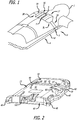
- FIG. 1 a chest compression belt fitted on a patient 1.
- a chest compression device 2 applies compressions with the belt 3, which has a right belt portion 3R and a left belt portion 3L.
- the chest compression device 2 includes a belt drive platform 4 and a compression belt cartridge 5 (which includes the belt).
- the belt drive platform includes a housing 6 upon which the patient rests, a means for tightening the belt, a processor and a user interface disposed on the housing.
- the belt includes pull straps 18 and 19 and wide load distribution sections 16 and 17 at the ends of the belt.
- the means for tightening the belt includes a motor attached to a drive spool, around which the belt spools and tightens during use.
- the design of the chest compression device allows for a lightweight electro-mechanical chest compression device.
- the fully assembled chest compression device weighs only 29 pounds, and is thus hand-portable over long distances.
- the device itself weighs about 22.0 to 23.0 pounds, with the battery, in at least one embodiment of the present invention, weighing between 2 and 5.0 pounds, and preferably about 3 pounds.
- the belt cartridge weighs about 0.8 pounds and the straps to secure the patient weigh about 1.6 pounds.
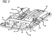
- FIG. 2 shows the posterior side 23 of the chest compression device as seen from the superior direction.
- the average sized patient's buttocks and the back of the patient's legs would extend past the inferior bumper 40.
- the device is built around a sturdy channel beam 41 that is laterally oriented with respect to the housing.
- the channel beam supports the device against the forces created during compressions.
- the channel beam also serves as the structure to which the belt cartridge is attached.
- the channel beam 41 forms a channel extending across the lateral width of the device.
- the belt is disposed in and travels along the channel.
- the belt is attached to a drive spool 42 that spans the channel.
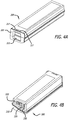
- FIG. 3 shows internal components of the chest compression device 2.
- a motor 79 is operable to provide torque to the drive spool 42 through a clutch 80 and a gearbox 81.
- a brake 82 attached to the superior side of the motor, is operable to brake the motion of the drive spool.
- the brake hub connects directly to the rotor shaft of the motor.
- the motor 79 and brake 82 are controlled by a processor unit 83, motor controller 84 and power distribution controller, all of which are mounted to the inside of the anterior cover plate 60.
- the processor unit includes a computer processor, a non-volatile memory device and a display.
- the processor unit is provided with software used to control the power controller and the motor controller. Together, the processor unit, power controller and motor controller make up a control system capable of precisely controlling the operation of the motor. Thus, the timing and force of compressions are automatically and precisely controlled for patients of varying sizes.
- FIGS. 2 and 3 also show the location of a battery compartment 121 near the head of the patient.
- the location and design of the battery pack and battery compartment allow for rapid exchange of batteries.
- a spring in the back of the compartment forces the battery pack out unless the battery pack is fully and correctly inserted in the compartment.
- a latch on one end of the battery pack engages a receiver in the battery compartment 121 to hold the battery pack within the batter compartment when the battery pack is inserted into the battery compartment.
- Recesses 120 indicate the location of the springs inside the battery compartment 121.
- Plastic grills 122 at the end of the battery compartment reinforce the recesses.
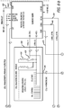
- FIGS. 4A and 4B are perspective views of a battery pack 200 showing the front and back sides 205, 210 of the battery pack respectively.
- Front side 205 of the battery pack faces outward and is visible to the user when the battery pack is inserted into the battery compartment 121 ( FIG. 3 ).
- front side 205 includes a latch 215 that engages a receiver within battery compartment 121 to hold the battery pack 200 within the battery compartment.
- a pair of raised tabs 217 disposed on the tops side of the front end of the battery pack. These tabs cooperate with the latch to ensure that the battery is properly seated in the battery compartment by prevent the top of the battery from riding up during battery insertion, forcing the latch into proper engagement with a battery latch receiver or lip of the battery compartment.
- connection 220 that connects to a connector within battery compartment 121 to enable electrical communication between the controller or processor of the mechanical compression device and the battery pack 200.
- This connector not only allows for the flow of current from the battery pack to power the mechanical compression device, but it also provides for the flow of data, programming commands and other information, such as battery charge status, discharge rate, time remaining until discharged, and the like between the battery pack and the processor or computer controlling the operation of the mechanical compression device.
- connector 220 may be configured to be connected to a connector in a battery charger to charge the cells of the battery pack, as well as to provide for the flow of data, software programs or commands and/or other information between the charger and the battery pack.
- connector 220 may be used to connect the battery pack to a communication network that would allow for flow of information between the battery pack and other computers, servers, processor or devices that are also connected to the network.
- the network may be a wired network, such as, for example, an Ethernet, or it may be a wireless network.
- the network may be a local network, or it may be a wide area network, such as a WLAN or the Internet.
- a status indicator 225 which may be, for example, one or more light emitting diodes (LEDs) or similar devices, is also disposed on the back end 210 of battery pack 200 to provide a visual indication of, for example, the charge/discharge status of the battery pack, the presence of any faults that would affect the operation of the battery pack, or other information that might be useful to the user of the battery.
- a push button 230 is also included; button 230 may be used, for example, to initiate a reset of the battery pack. Alternatively, button 230 may be used to initiate a diagnostic test, the results of which may be indicated by status indicator 225. In other embodiments, pressing button 230 may initiate other functions of the processor in the battery pack, including, for example, and not by way of limitation, determining the remaining capacity of the battery, display of fault codes through the use of status indicator 225 and the like.
- FIG. 5 is an exploded perspective view of the battery pack 200.
- the battery pack 200 in this exploded view has been inverted from the view of FIGS. 4A and 4B .
- the battery pack has a bottom enclosure 234 and a top enclosure 232.
- a battery latch assembly having a battery latch 236, a lever base 238 and a lever latch 240 is mounted at the side of the battery pack facing outward when the battery pack is inserted into a battery compartment, and is held in place by the bottom and top enclosures.
- Lever latch 240 has a wing 241 that is inserted into a groove or slot 243 formed in a face of battery latch 236, and lever base 238 is mounted on the bottom enclosure to pivotally hold lever latch 240 in the enclosure.
- Compression springs 254 are disposed between a bottom end of battery latch 236 and top enclosure 232.
- a projection 255 is disposed a top end of battery latch 238, and is configured to protrude through slot 251 that extends through a thickness of the bottom enclosure 234.
- battery latch 236 may be manipulated by a user to engage and disengage projection 255 from the latch receiver located in the mechanical compression device to insert the battery pack into the battery compartment and to release the battery pack for removal from battery compartment 121.
- a battery entry board 242 Disposed at the back end 210 of the battery pack is a battery entry board 242 to which is mounted connector 220, indicator 225 and button 230 ( FIG. 4B ).
- Entry board 256 is mounted to bottom enclosure 232 using one or more screws 250.
- the entry board may also be fastened to top enclosure 252 using one or more screws 256.
- a water resistant gasket 262 may be used to resist the incursion of fluids into the interior of the battery pack.
- a label 260 may be used to provide information to a user relative to the various indications that may be provided by indicator(s) 225.
- Battery cell assembly 246 includes one or more battery cells 248.
- Battery cells 248 may be cells utilizing a variety of battery chemistries, such as, for example, nickel metal hydride, lithium hydride, lithium-ion and the like.
- Battery management board 244 and battery cell assembly 246 may also include a pair of splatter shields 266 mounted on left and right sides of battery cell assembly 246 to protect the terminals of the individual battery cells 248 from inadvertent contact with other parts of the assembly, thus providing a shield against short circuit of the battery cells.
- Battery pack 200 also includes at least one vent 264, shown disposed in the top enclosure to allow for venting of the battery pack to prevent buildup of potentially flammable or explosive gases produced by the battery cells 248 during charging or discharging of the battery pack. While shown disposed in the top enclosure, those skilled in the art will appreciate that the vents may be disposed through any wall or side of the battery pack. Vents 264 may be a simple hole extending through the wall or side of the battery pack. Alternatively, vent 264 may include a filtering means 265, such as a screen or hydrophobic membrane to prevent the incursion of particulates or fluids or moisture into the interior of the battery pack.
- An additional advantage of such vents is that the vent or vents provide for equalization of pressure between the interior and exterior of the battery pack, such as may occur when the battery pack is transported to a higher or lower altitude.
- the mechanical compression device described above requires a reliable power source to operate. It is not unusual for the device to be required to be used for thirty minutes or more to provide resuscitation to a patient in an emergency.
- the torque and power requirements of the motor of the mechanical compression device require up to a peak of seventy amperes of current during compression. If enough current cannot be delivered by the battery to the motor controlling the compressions, the voltage falls off and the motor may not be capable of generating enough torque to ensure complete compression of a patient's chest.
- the inventors of the present invention have realized that having a very low total internal resistance is key to ensuring extended and reliable operation of the battery when the battery is under a constant power drain.
- One such battery chemistry that has been found to be useful in devices requiring high power is a battery using Lithium Ion chemistry, such as the model ANR26650M1-A or ANR26650M1-B Lithium Ion cell available from A123 Systems, Incorporated.
- FIG. 6 is a schematic diagram illustrating one embodiment of a battery pack 300 in accordance with the present invention.
- Battery pack 300 includes eleven Li-Ion chemistry cells, such as the model ANR26650M1-A or ANR26650M1-B cells described above. Each cell provides 3.3 volts, and the eleven cells are connected in series to provide a total of 36.3 volts.
- a battery pack in accordance with principles of the present invention can be manufactured that weighs approximately three pounds.
- Such a battery has been observed to deliver between 1550 and 2000 watts, and preferably deliver a peak power of 1800 watts. This provides a desirable weight to power ratio.
- such an embodiment has also been found to be able to deliver energy of slightly less than 100 watt/hours. While eleven battery cells are used in this exemplary embodiment, more or less cells could be used depending on the requirements of the device to be powered.
- the Lithium Ion (Li-Ion) cells used should have low internal DC resistance, preferably below 15 milliohms, and more preferably below 12.5 milliohms per cell.
- Li-Ion batteries are capable of providing the voltage and current required to operate a mechanical compression device for extended periods of time, care must be taken during both the discharge phase, and recharge of the batteries to ensure that the batteries continue to function for their desired lifetimes. It is well known that Li-Ion cells should not be over charged, nor should they be over discharged. Accordingly, various embodiments of the present invention include the capability of monitoring and controlling both the discharge of the cells and the recharging cycle. Those embodiments will be discussed in more detail below.
- Bus 320 has both a positive side and a negative, or ground side, as is typical for a DC circuit.
- Bus 320 delivers the direct current provided by the battery cells to a load (in this example, the mechanical compression device) through an interface 330.
- interface 330 is a pin connector having seven connection pins.
- a socket could be used, or a combination of pins and sockets, with more or less than seven pins or sockets could be used.
- bus 320 The positive side of bus 320 is connected to pin 7 of interface 330. Similarly, the negative side of bus 320 is connected to pin 6 of interface 330. Pins 1-5 of interface are used to communicate various signals involved in the monitoring and control of the battery pack, as well as for communication to the device that is being powered, enabling the exchange of information and control signals between the battery pack and the powered device. Various exemplary embodiments of the invention incorporating those features will be discussed in more detail below.
- the positive side of bus 320 includes a fuse 342 to protect the circuit from over current conditions.
- Fuse 342 may be, for example, a 30 ampere fuse. In such a case, a sustained current flow through fuse 342 of more than 30 amperes would cause the fuse to open, breaking the circuit created by bus 320 and stopping the flow of current from the battery cells.
- there is also a blown fuse detector circuit that monitors the fuse, and, if the fuse is blown, provides a signal to the pack controller that the fuse is blown. The pack controller may then provide a signal indicating that the battery is not suitable for use.
- Such a signal may be the change in color of and LED, or activation or de-activation of some other status indicator.
- the pack control may provide a signal to the equipment powered by the battery, which may then provide an indication to a user that the battery is not ready for use.
- the positive side of main bus 320 also includes a number of n-channel field effect transistors (n-FET) 340, 350 and 360. These n-FETs provide for switching and control of the circuit. N-FETs are used because they provide a very low resistance switch in keeping with the design requirement of minimizing the total internal resistance of the battery. Another unique capability of the n-FET is that they are capable of conducting high current loads, without damage and without generating excessive amounts of heat.
- One example of an n-FET that has been found suitable for use in various embodiments of the present invention is the model IRLS3036, available from Digi-Key Corporation.
- p-FET devices In typical designs, p-FET devices would be used as the switches and would be placed in the high side of the main bus. However, p-FETS have two or more times the on resistance of an n-FET device. Thus, to handle the same current as an n-FET device, several p-FETs wired in parallel would be needed. Moreover, use of several p-FETS may also require the use of a heat sink to dissipate heat generated while the p-FET is on. This is disadvantageous where space within the battery pack is limited.
- an n-FET device would typically be used in the low side of the main bus to switch the current on and off in the bus.
- use of an n-FET in this situation breaks the ground of the battery, which may cause noise in the circuit and interfere with communication between the various elements of the battery management system circuitry.
- the inventions have placed the n-FET switches in the high side of the bus, which provides efficient switching of the bus without the generation of excess heat that may occur when p-FETs are used. Placing the n-FETs in the high side of the bus also eliminates the problem of breaking the ground of circuit.
- one or more resistors may be inserted in the negative, or low, side of the main bus circuit. These resistors provide the ability to tap the main bus to monitor various aspects of the current flowing through the circuit.
- resistor 370 is connected across the input lines of a cell balancing and primary protection circuit, which is discussed in more detail below.
- a typical value for resistor 370 is, for example, 2.5 milliohms.
- resistor 380 may be connected across a state-of-charge monitor, also known as a "gas gauge.” In this embodiment, the value of resistor 380 may be, for example, 5 milliohms.
- Each of the cells 310 is individually monitored during both charging and discharging to control the rate of charging and discharging, respectively.
- a separate cell tap line 390 is connected to each cell and to a cell monitoring and balancing circuit 400.
- a monitoring system on a microchip which may be, for example, battery pack protection and monitor integrated circuit (IC) 410 such as an OZ890 available from O 2 Micro, is used to control the charging of the various cells.
- IC battery pack protection and monitor integrated circuit
- cell monitoring line 390 provides a positive signal to a representative pin input of IC 410.
- cell 1 is monitored using input line BC1 of IC 410, and so forth up to cell 11, which is monitored using input line BC11 of IC 410.
- IC 410 If the control circuitry of IC 410 detects an imbalance in a cell, IC 410 provides a signal on an appropriate external bleed control line CB1-CB11. As shown in FIG. 6 , when the signal on the appropriate external bleed control line is applied to the gate of n-FET 420, current is allowed to pass between the source and the drain of n-FET 420 and then through resistor 430, which results in bypassing the cell and halting charging of the cell. As can be seen from FIG. 6 , each cell has its own dedicated combination of resistor and n-FET in electrical communication with IC 410 for monitoring each cell and preventing each individual cell from over charging.
- Cell balancing and primary protection IC 410 may also be used in some embodiments to monitor the total voltage of the battery cell pack. For example, when all of the cells have attained their maximum voltage, IC 410 can send a low signal to the gate of n-FET 350 to open the channel between the source an drain of n-FET 350 and thus open the main bus circuit 320. This results in a cessation of charging current through the cells, and thus halts the charging process.
- IC 410 monitors the voltage across the cells during discharge of the battery. When the voltage across the cells drops below a threshold level, for example, 21 volts, IC 410 drives the signal on line 450 low, which in turn shuts off n-FET 360 which interrupts the main bus circuit. This prevents damage to the battery cells that may be caused by removing too much of the charge in the cells, which may result in decreased life of the cell.
- a threshold level for example, 21 volts
- IC 410 may also include and control a temperature measurement capability designed to monitor the temperature of the battery pack and/or individual battery cells to prevent overheating.
- one or more thermistors 460 are used to provide temperature signals over line 470 to the IC 410. If IC 410 determines that the temperature of the battery is either too high or too low, IC 410 may drive either or both of n-FETs 350 and 360 low, opening the main bus 320 and isolating the battery pack. It will be understood that while only a single line 470 is shown for clarity, line 470 includes an appropriate number of conductors to monitor the function of all thermistors used in the temperature monitoring circuit in communication with IC 410.
- IC 410 may additionally provide a visual indication of fault state by providing a fault signal on line 480 that may then be used to cause LED 490 to light up.
- This visual signal of a fault condition sensed by the primary protection circuit indicates that the battery pack has been rendered non-functional by IC 410 and that repair or maintenance of the battery pack may be required.
- Some embodiments of the present invention may also include secondary protection against catastrophic faults or over voltage protection.
- Such secondary protection may be provided by a variety of circuits designed to monitor the voltage of the battery pack and/or the current flow through the main bus and to take action when certain thresholds values of current or voltage are exceeded.
- such protection may be provided by an integrated circuit 500, such as, for example, the OZ8800 available from O 2 Micro.
- an integrated circuit 500 such as, for example, the OZ8800 available from O 2 Micro.
- the OZ8800 secondary level battery protection integrated circuit can monitor three to seven individual cells. Thus, where eleven cells are used, two OZ8800s will be required.
- IC 500 monitors the voltage of each cell over monitoring line 312. In some embodiments, a time delay may be employed that provides for temporary over voltage conditions to exist. Where the time threshold is exceeded because the voltage did not drop back into an acceptable range, IC 500 sends a low signal over fault line 510 to n-FET 340 to turn off n-FET 340. Each cell is monitored by a similar circuit.
- n-FETs described above are in a normally off state unless a positive voltage is applied to the gate of each n-FET.
- any fault that results in voltage decrease to a level below the threshold of the n-FET at the gate will cause the n-FET to open, thus providing additional protection to the cells and battery management circuitry.
- Another embodiment of the present invention includes a "gas gauge” function that monitors the amount of useful charge remaining in the battery pack.
- gas gauge functionality can be provided using integrated circuits designed to carry out vary tasks, such as to calculate remaining battery capacity for use and standby conditions based on time of use, rate of discharge and the temperature of the battery. Such a circuit may also determine the true battery capacity in the course of a discharge cycle from near full charge to near full discharge states.
- FIG. 6 illustrates one example of such a gas gauge circuit 600.
- Monitoring of the battery pack is accomplished using an integrated circuit 610, such as a bq2060A available from Texas Instruments, Inc.
- IC 610 works in conjunction with an external EEPROM 620.
- EEPROM 620 stores configuration information for IC 610, such as the chemistry used in the battery cells, the self-discharge rate of the battery, various rate compensation factors, measurement calibration, and battery design voltage and capacity. All of these settings can be changed to allow the system to be used with a variety of battery types.
- IC 610 can communicate with a central processor and memory over a back-side bus circuit 630.
- IC 610 and EEPROM 620 may be configured, using control signals from the central processor, to accommodate different types of batteries that are detected and identified by other circuitry included in the system, or which are manually identified by a user.
- IC 610 may also cooperate with the pack controller to augment the reporting accuracy of the gas gauge in instances of low current draw using appropriate control commands embedded into the software that controls the operation of the pack controller and the gas gauge to implement the algorithms necessary to carry out this function.
- the gas gauge functions are carried out by IC 610 in conjunction with IC 800 to determines full charge battery capacity and the capacity remaining at any point in time by monitoring the amount of charge input or removed from the battery cells.
- IC 610 measures battery voltage, battery temperature and current as detected across resistor 380.
- IC 610 also, in some embodiments, may estimate the self-discharge rate of the battery, and also monitors for low-voltage thresholds of the battery.
- IC 610 measures the amount of charge and discharge of the battery by monitoring the voltage across resistor 380, which is located between the negative terminal of the first cell 310 (of the series connected cells) the negative terminal of the battery pack. Available battery charge is determined from this measured voltage and correcting the measurement for environmental and operating conditions.
- IC 610 may also measure the temperature of the battery pack so as to carry out the estimations and adjustments described above.
- a thermistor 640 is mounted adjacent to a cell or cells of the battery pack in such a manner as to be able to measure the temperature of the cell or cells of the battery pack.
- IC 610 drives the gate of n-FET 650 high by providing an appropriate signal over line 660 to connect a bias voltage source to thermistor 640 while the temperature of the cell or cells is being measured. Once the measurement is completed, IC 610 drives the gate of n-FET 650 low, opening the n-FET and thus disconnecting thermistor 640 from the bias source.
- IC 610 may be reset each time the battery is charged so that the reported amount of charge remaining in the battery is accurate.
- a battery pack supervisor circuit or pack controller 800 provides a signal over reset line 670 to drive the gate of n-FET 680 high. This causes the current to flow through n-FET 680, resulting in a reset signal being provided to IC 610 to reset the battery capacity counter of IC 610.
- IC 610 may include a seal/unseal function that prevents unauthorized access to the parameters stored in the IC 610 or EEPROM 620.
- Pack controller 800 may send a signal over line 680 that drives the gate of n-FET 690 high, which closes n-FET 690 allowing for commands and data to flow between IC 610 and EEPROM 630.
- Such data may include, for example, updated calibration information and the like.
- the flow of data between IC 610 and EEPROM 630 may be controlled using only software commands from the pack controller to control IC 610 and EEPROM 630 without requiring n-FET 690.
- the battery management system includes a pack controller 800 which serves as an overall supervisor for the various functions carried out by the battery management system.
- Pack controller 800 will typically be an integrated circuit, although discrete circuitry carrying out the same functions could be used, depending on the amount of space available within the confines of the battery pack.
- pack controller 800 may be a low or ultra-low power microcontroller such as the MSP430F2418 Mixed Signal Controller available from Texas Instruments Incorporated. Such a controller may include memory, such as random access memory or flash memory to provide for rapid and efficient execution of the various functions of the battery management system. Pack controller 800 also has the capability of communicating with peripheral devices, circuitry or memory over one or more communication buses, such as backside bus 630 and front-side 810.
- the communication busses typically use a communication protocol such as, for example, the I 2 C bus (a Trademark of Philips Incorporated) or the System Management Bus (SMBus).
- the SMBus is described in more detail below.
- Appropriate software commands are used to program the functions of the pack controller 800.
- Such software includes commands configuring the communication protocol interface, such as for example, the SMBus interface.
- the software would also configure the pack controller to monitor critical battery pack parameters, which are made available to it over communication lines 810, 820, 822, back-side bus 630, front side bus 810 and detect line 824, as well as other communications lines not shown or which may be added in the future.
- pack controller 800 is also in communication with one or more memory devices, such as, for example, an event archive EEPROM 900.
- an event archive EEPROM 900 has, for example, although not limited to, 64 kilobytes of memory that can be used to store history of various events that occur during the charge and discharge cycles of the battery pack, such as, for examples, the total amount of charge, total amount of energy discharged, the temperature of the battery cells, any faults that occur, or other information related to the individual battery cells and/or the various circuits employed to manage and control the operation of the battery.
- Pack controller 800 may also be programmed to communicate with memory and/or processors such as, for example, EEPROM 1000.
- EEPROM 1000 may be located in a mechanical compression device that is powered by the battery pack, or it may be incorporated into the battery pack and configured to be accessed by the devices to be powered by the battery.
- pack controller 800 communicates with EEPROM 1000 and/or a processor in the mechanical compression device over front side bus 810, which accesses a similar bus in the mechanical compression device through connector 330. In this manner, a two-way communication connection may be established between the battery pack and a device powered by the battery pack to allow for exchange of information between the battery pack and the powered device.
- updated operating parameters or commands may be loaded into the battery pack from the powered device when the battery pack is put into communication with the powered device.
- information contained in the event archive EEPROM 900 may be transmitted to the EEPROM 1000, or any other memory (such as a portable memory device) configured for communication over back-side bus 810 from any of the memories present in the battery pack.
- this communication capability also allows the battery to communicate with other devices besides devices which will be powered by the battery.
- the battery pack will be removed from a powered device to be recharged.
- the battery charger may be used to retrieve information from the memory or memories of the battery pack, and/or transmit updated data, information, programming commands or software to the battery through front-side bus 810.
- This communication process will typically be managed using various handshaking and communication dialog as set forth in the communication protocol used to enable the communication, such as the SMBus protocol, exchanged between a processor residing in the charger or other device and the pack controller 800 of the battery pack.
- the battery may also be trickle charged when the battery is inserted into the device to be powered, where the device being powered is also connected to an external power supply.
- pack controller 800 may include a capability, managed by pack controller 800, of recognizing when the battery pack is inserted into a battery charger or device to be powered, such as a mechanical compression device.
- pack controller 800 may be configured using appropriate software and/or hardware commands to provide a signal to IC 410 and IC 500 to provide a high signal to the gates of n-FETs 340, 350 and 360 to close those switches and thus provide full battery voltage at the positive and negative pins of connector 330 only when detect circuit 1100 sends an appropriate signal to pack controller 800 over line 824 indicating that the battery pack is properly mounted into a device to be powered.
- pack controller 800 monitors a line connected to a mechanical switch or interlock that is forced closed when the battery is properly inserted into a charger or a device to be powered. In another embodiment, pack controller 800 monitors a signal line connected to one or more pins of the battery connector. When an appropriate signal is received over this signal line, pack controller 800 determines that the battery is inserted into a charger or a device to be powered, and provides a high signal to the gates of n-FETs 340, 350 and 360 as described above.
- pack controller 800 may be programmed to respond only when a particular signal is received, ensuring that the battery is inserted into a specific type or make of a charger or device to be powered designed to accommodate the battery before providing the high signal to the gates of n-FETs 340, 350 and 360.
- Pack controller 800 may also be programmed to provide password access to allow for changing of settings and parameters stored in EEPROMs 900 and 620, as well as to provide appropriate signals to drive LED 490 in the event of a fault. Additional capabilities may also be included, configured using appropriate software and/or hardware commands, to provide additional functions to the battery management system. For example, such functions may include driving a display that indicates the total amount of charge remaining in the battery and the like.
- pack controller 800 A more complete description of the various capabilities that can be incorporated into pack controller 800, particularly when pack controller 800 is an MSP430F2418 (or other members of this controller family) is contained in a document entitled " MSP430F241x, MSP430F261x Mixed Signal Microcontroller,” SLAS541F - June 2007 - Revised December 2009 available from Texas Instruments Incorporated , the entirety of which is hereby incorporated herein by reference.
- the various processors and integrated circuits and logic systems incorporated into the various embodiments of the present invention are capable of functioning as a unified system due to their ability to communicate with one another over the front side bus 320 and the back side bus 630.
- the communications over these buses are carried out using the System Management Bus (SMBus) specification.
- the SMBus is a two-wire interface through which various system component chips, such as IC 410, IC 610, the secondary protection system 500, event archive 900, EEPROM 1000 and pack controller 800, among other circuitry, can communicate with each other and with the rest of the system. Further information related to the SMBus specification is contained in "System Management Bus (SMBus) Specification Version 2.0," SBS Implementers Forum, August 3, 2000 , the entirety of which is hereby incorporated herein by reference.
- SMBus System Management Bus
- the inventors have observed that, in some embodiments of the invention, the voltage required to drive the n-FETs closed exceeds the voltage that is available from the battery pack. For example, using an n-FET that requires a bias voltage of 10 volts, the n-FET requires a drive voltage of the bias voltage plus the battery voltage to drive the n-FET sufficiently to allow an appropriate voltage to pass through the n-FET to charge or discharge the battery. Accordingly, a voltage boost circuit is included to boost the voltage supplied to the gates of the n-FETs to drive the n-FETs to conduct the current supplied by the battery cells.
- n-FETs in the present invention results in the need for complex circuitry, such as the boost circuit. Such complexity could be eliminated using p-FETs.
- the heat generated using multiple p-FETs may require the addition of one or more heat sinks to dissipate the heat, which may require more space in a compact battery than which is available.
- p-FETs have at least twice the on resistance of n-FETs, which would increase the overall internal resistance of the battery pack.
- pack controller 800 is in communication with event archive EEPROM 900.
- event archive EEPROM 900 is a non-volatile memory device, such as a flash memory device, having, for example, 64 kilobytes of memory capacity.
- the pack controller 800 may store data and information related to usage, operation and performance of the battery pack in event archive 900 for later retrieval and analysis.
- Table 1 is an exemplary listing of data or information related to the long term history of the battery that may be sensed or collected by pack controller 800 during the lifetime of the battery and then stored in the event archive 900. It will be understood that while certain fields are shown, other data fields may be used, depending only on the design requirements of the system.
- CRC cyclic redundancy check
- FCC full charge capacity
- RC remaining capacity
- the clock field may be updated whenever the battery's runtime archive is changed. In case the battery loses power completely, the battery can use this field to reset its clock to the latest recorded time. This ensures that the timestamp in all history records stored in the memory increases with time, even after a power loss, to facilitate reassembly of the complete history data downloaded from the battery memory. Although it is not possible to account for the time lapse during a power loss, the time lapse may be estimated from the gap in the timestamps of individual history records.
- the clock field may also be updated using data received from global position satellites, in those embodiments where a GPS receiver, or other similar technology, such as location technology based on cellular telephone technology, is included in the battery.
- the data and information stored in the battery may also be related to run-time events that are recorded as they occur. For example, data or information related to an actual use of the battery may be recorded.
- the data and information stored in the battery may include data related to the current operation of the battery.
- data and information is commonly referred to as "run time” information or data.
- Table 2 is an exemplary listing of data or information related to the current operation, or run time, history of the battery that may sense or collected by pack controller 800 during the lifetime of the battery and then stored in the event archive 900. It will be understood that while certain fields are shown, other data fields may be used, depending only on the design requirements of the system.
- the run time information and data stored in the EEPROM 900 may be stored in a predetermined format. Once example of such a format, used to store the data listed in Table 2, is shown in Table 3 below: Table 3 Byte/Unit 1-4 5 6 7-15 16 Data field Timestamp, sec Event ID Parameters total length, byte Parameter(s) CRC
- a data record 16 bytes long is constructed using the data and information listed in Table 2. Additionally, the record includes a timestamp, stored in seconds, for each recorded event.
- the parameter stored in the data record is a 2 byte long error code.
- Such a code may be useful when the data is analyzed in troubleshooting the error in operation of the battery or the device being powered and determining any correction that needs to be made to prevent the error from occurring in the future. Additional data may be included as needed depending on the fault detected.
- the error code may also be the result of a self-test performed on the battery systems by the battery management system pack controller 800, or one of the other processors resident in the battery management system. Such a self-test may be initiated either automatically, such as in the event of a detected problem, or according to a predetermined schedule, or in response to a command from a user.
- the processor may test the various functions of the components of the battery management system and/or the battery cells to determine if they are functioning within acceptable parameter rangers.
- the temperatures sensors measuring the temperature of the battery or of individual battery cells may be polled periodically, such as, for example, every thirty (30) seconds.
- the results of the self-test may be recorded in EEPROM 900 as described above.
- the pack controller 800 may provide a visual indication of the results of test by sending a signal to the battery charger or device being powered to control an indicator or a display. A visual indication may also be provided by sending a signal to the LEDs of the battery pack.
- the pack controller 800 may control the n-FETs of the battery management system to open the main bus, effectively turning the battery off. Such a condition may require removal of the battery from the powered device or charger and insertion (or re-insertion) into a battery charger before controller 800 will allow the battery to provide current to a device.
- the "powered device operation power drain” event is recorded while the device to be powered is in active operation.
- the battery monitors the power and writes the current, voltage and temperature associated with the peak power provided by the battery, along with the remaining charge in the battery, as determined by the gas gauge, to the archive in 5-minute intervals.
- Each of these parameters requires two bytes of the data record, for a total of eight bytes.
- the "mode change” event provides a record of each time the operating mode of the battery is changed, along with the battery voltage and remaining charge available at that time.
- "Low power” mode occurs when the pack controller 800 disables the battery because the power remaining in the battery has fallen to an extremely low level. The battery also enters this mode when the pack controller 800 wakes up after losing power, most likely during a wakeup charge. Once the battery has enough charge to resume normal operation, controller 800 provides a signal indicating that the battery is now in the "In Device” mode.
- the battery voltage, remaining capacity and adjusted remaining capacity of the battery as determined by the gas gauge each require two bytes, for a total of seven bytes for this event. The adjusted remaining capacity is adjusted for scale, offset and time the battery has been inactive.
- the "battery state at start of charge” event requires seven bytes and is written when charging of the battery is initiated.
- a condition cycle is initiated when the battery is first charged, or after a deep discharge.
- the data in this field will be recorded in EEPROM 900 when the battery voltage is sufficient to power up pack controller 800.
- the “battery state at end of charge” event is similar to the “battery state at start of charge” event, except that it is the battery voltage, full charge capacity, peak battery temperature, peak temperature ID, and remaining charge that is stored. Both the full charge capacity and remaining charge are acquired from the gas gauge. In the event that charging is interrupted for any reason, such as, for example, the battery is withdrawn from the charger before charging is complete, this event is not written to EEPROM 900. This event requires a total of nine bytes in the data record.
- the "load test result” event records the result of a test that is performed on the battery by the charger when the battery is in the charger.
- the results of the test are recorded in EEPROM 900 by the battery charger over communication line 810.
- the end-of-life warning is an indication that the battery is approaching its service life, and may need to be replaced soon.
- the "BCP event” is recorded when a new battery configuration parameter (BCP) is uploaded to the battery.
- the battery configuration parameter includes fields for revision number and a flag that identifies the direction of data flow; that is, data flowing into, or out of, the battery.
- the BCP also includes test criteria for controlling the load test.
- the new BCP will not be saved into the memory of the battery, and this event will not be generated, and thus this event will not be stored in the EEPROM 900.
- This event requires a total of four bytes, with two bytes reserved for the revision number of the old BCP stored in the battery before the upload, and two bytes reserved for storing the revision number of the new BCP that has been uploaded, verified and stored in the memory of the battery.
- the "initialization complete” event is recorded upon the completion of the first initialization of the battery to record the version of the software loaded into the battery. This event records whether the software revision is a minor or major revision, and is recorded only once in the battery's lifetime, since a software revision will cause this event to be overwritten with the new software version.
- Data identifying the battery such as a serial number or collection of alpha numeric characters may also be stored in the EEPROM 900, or in other memory associated with the various processors or circuits of the battery management system. This identification information may be useful when the data is retrieved from the memory and analyzed.
- the pack controller 800 may be programmed to accept data provided to it through the front side, or smart bus, 810 by either a battery charger, or a device which is being powered by the battery.
- the device to be powered for example, the mechanical compression device described above, may have a processor and communication system that can transmit data or information to the battery that is related to the actual use of the mechanical compression device. The battery would then be used as a carrier of the information, which could then be retrieved from the event archive memory when the battery was recharged or serviced.
- FIG. 7 is a schematic illustration of one such system.
- a battery 1300 having data and information stored within an event archive EEPROM memory, is inserted into a charger 1310 for recharging after use.
- Charger 1310 includes a processor 1330 which is in operable communication with a memory 1320 and a communication circuit or port 1340.
- the processor 1330 sends a data retrieval request to the pack controller of the battery to retrieve data and/or information from the event archive memory of the battery.
- a communication session may be established between the processor 1330 and the pack controller of the battery, wherein the data and/or information stored in the event archive of the battery is communicated to the processor 1330 of the charger.
- the pack processor 800 controlling the operation of the battery may be programmed to transmit the information to a central server.
- memory 1320 may be any storage media that is capable of being written to and read by a processor, and may preferably be a non-volatile memory such as flash memory or it may be a storage media such as a hard disk drive.
- processor 1330 may also communicate the retrieved data and/or information to a storage device external to the charger, such as a computer 1350 which in turn has its own memory or storage media, using the communication port 1340.
- the data and/or information retrieved from the battery may be stored in the memory 1320 of the charger until such time as the charger is commanded to communicate the data and/or information to another computer, server or other system for analysis.
- the charger may be capable of communicating over a wired or wireless network, such as is illustrated by telephone line 1360 using appropriate communication hardware and software using a modem connected to a computer or the charger, to communicate the data and/or information to another system, such as a server 1370 located remotely from the charger 1310. While the invention is discussed in relation to "a server,” those skilled in the art will understand that "a server” also includes systems where the server functions are distributed among more than one physical "server” units.
- the charger may be capable of communicating through a LAN/WLAN 1380, which may be a local area network, a wide area network, the Internet and the like to communicate the data and/or information retrieved from the battery to server 1370.
- a communication process may be carried out through a wired system, or with the addition of appropriate hardware to the charger, such as a network card, wireless modem and the like, may be accomplished wirelessly.
- FIG. 8 illustrates yet another embodiment of the present invention wherein the battery archive memory is used to facilitate distribution of updated data, information, operating parameters and software that is used by the processors of the battery management system to monitor and control the operation of the battery during the battery's lifetime.
- battery pack 300 includes various processors and controllers, such as, for example, pack controller 800, primary protection circuit 410, IC 510 and memories such as EEPROM 1000, EEPROM 900 and EEPROM 620, among others.
- the processors are configured to control the operation of the battery, and the memories are configured to store, among other data and information, operating parameters used to control the operation of the battery and/or software programming that is used to program and control the processor to carry out the tasks required by the designers of the software.
- the memories may store information related to or associated with the operating parameters and/or software, such as, for example, a version number associated with a particular version of the parameters or software, or the memories may also be used to accumulate and store data related to the usage of the battery or equipment, performance characteristics or system configuration of the battery, charger or equipment powered by the battery, and maintenance data related to the operation of the battery, charger or equipment powered by the battery.
- the data stored and transferred by the battery to and from the charger or equipment powered by the battery may also include historical information related to individual batteries or pieces of equipment that the battery has been in communication with, where the data includes an identifier that allows the data to be analyzed to determine the operational history and/or performance of the individual battery, charger or piece of equipment.
- the data may also include location data identifying the location of the charger or equipment to facilitate location of the charger and device in the event there is a need to locate the charger or equipment.
- Examples of equipment powered by batteries that may benefit from the various embodiments of the present invention include, but are not limited to, battery powered medical devices, defibrillators, mechanical compression equipment, and any other equipment that is not typically connected by either a wired or wireless communication network yet still require to be tracked and/or updated on a periodic basis to ensure that the devices or equipment are operating with the most up to date data, configuration information, performance specifications, operating parameters and software programming available.
- One common element in a system using rechargeable batteries to power equipment is that the batteries need to be recharged. Often, to save weight in the equipment using the battery, if the equipment is designed for portability, the batteries are removable from the equipment so that they may be charged outside of the equipment. Thus, the portable equipment is not required to include battery charging circuitry.
- the charger includes a processor and a memory.
- the processor is controlled by software commands that may be imbedded in the processor, or they may be stored in a memory and retrieved from the memory by the processor as needed.
- Such programming and control schemes are well known to those skilled in the art, and will not be described in detail herein.
- a battery may have an updated revision of operating parameters or software commands stored within the memory of the battery.
- the processor of the battery, the charger, or both check the version of the operating parameters or software in the memory of the batter with the version that is present in the memory of the charger. If the version on the battery is later than the version stored in the memory of the charger, the memory of the charger is updated with the updated version of the operating parameters and/or software present on the battery.
- the version of the operating parameters and/or software present in the memory of the charger is later than the version stored in the memory of the battery, the latter version of the operating parameters and/or software stored in the charger is downloaded into the battery. In this manner updated versions of the operating parameters and/or software programs can be propagated across a fleet of batteries used to power equipment.
- a battery in another embodiment, can be used as a carrier to distribute or retrieve data generated during usage of the battery and/or equipment.
- data may include, for example and without limitation, historical operational data, maintenance data and the like.
- one or more of the chargers or pieces of equipment powered by the battery may be in communication with a centralized network or server through a communication system such as the internet or other wired or wireless network or communication line.
- a communication system such as the internet or other wired or wireless network or communication line.
- updated data, operating parameters, configuration information and software programs may be pushed out to the one or more chargers and/or pieces of equipment in communication with the network or server by, for example, a processor on the network or server suitably configured by appropriate software.
- the one or more chargers or pieces of equipment may periodically query the network or server to determine if there are updated data, operating parameters, configuration information and software programs present on the network or server that need to be downloaded from the network or server to the charger or piece of equipment, and if so, accept the updated data, operating parameters, configuration information and software programs from the network or server and store them in the memory of the charger or piece of equipment.
- the updated data, operating parameters, configuration information and software programs is downloaded into the memory of the battery.
- the battery When the battery is next inserted into a charger or piece of equipment that does not have the updated data, operating parameters, configuration information and software programs in its memory, the battery then uploads the updated data, operating parameters, configuration information and software programs to the memory of the charger or piece of equipment, thus facilitating the rapid distribution of the updated data, operating parameters, configuration information and software programs throughout the user base of chargers and pieces of equipment powered by the battery.
- FIG. 8 is a schematic illustration of the use of a battery in accordance with various embodiments of the invention as a carrier.
- Updated data, information, or software programming (hereinafter, collectively, “data") 1405 is communicated to a charger 1410.
- Data 1405 may be communicated to charger 1410 by a computer in communication with charger 1405.
- charger 1410 may be connected to a network, server, or other source of data.
- battery A 1415 may contain the data 1405, and communicate the data 1405 to charger 1410 when battery A 1415 is inserted into charger 1410 for recharging.
- updated data 1405 may have been stored in the memory of the battery by a processor in powered device 1420 when battery 1415 was inserted into the powered device, as illustrated by broken line 1425.
- the next battery to be inserted into charger 1410 in this case, battery B 1430, may become a carrier for data 1405 if the memory of battery 1430 does not already contain data 1405.
- the processor of the battery such as pack controller 800, will control the download of the data 1405 from charger 1410 to the memory of battery B 1430.
- the processors of device 1420 and battery B 1430 communicate to determine if the data stored in the memory of device 1420 is an earlier or later version of the data stored in the memory of battery B 1430. If the data stored in the memory of device 1420 is an earlier version, then the data 1405 is uploaded from the memory of battery B 1430 to the device 1420. If the data stored in the memory of device 1420 is a later version than data 1405, then the processors may decide either to download the later version of data to battery B 1430, replacing data 1405 with the later version for further transmission other devices, chargers and batteries, or the processes may decide that no transfer is to take place, and data 1405 is not uploaded into device 1420.
- battery B 1430 has the latest version of data 1405 stored within its memory
- processor of battery B 1430 communicating with the processor of charger 1435 to determine whether battery B 1430 or charger 1435 has the latest version of the data.
- the data in battery B 1430 is either uploaded into the memory of charger 1435, where it is now available to update the data in other batteries, such as battery C 1440, or a new version of data will be downloaded from charger 1435 into battery B 1430.
- battery C 1440 may again have the data in its memory updated when it is inserted into charger 1435. Battery C 1440 may then transmit updated data 1405 into powered device 1445 when battery C 1440 is inserted into device 1435
- This process continues virally, that is, it spreads the updated data from charger to battery to powered device in an automated fashion that helps to ensure that each battery, charger and powered device are operating using the latest data, information and/or software programming.
- the battery may also include circuitry for determining where the battery is located, such as circuitry that can communicate with a global positioning satellite and analyze the position of the battery from those communications using methods well known in the art. Such location information could then be stored in the event archive memory of the battery for later analysis and tracking of the location of the battery.
- the battery may also include an accelerometer that may provide data and information related to the handling of the battery that can be stored in the archive memory of the battery. Such data may be useful in determining the kind and level of forces that the battery experiences during use and transportation, and may be useful in improving the design of the battery to prevent damage during use and transportation to extend the life of the battery.
- the data gathered from the accelerometer may also be used in real time to detect when the battery or device in which the battery is inserted has been subjected to a shock that may have caused damage to the battery or device to be powered.
- the data is processed by the pack controller which may determine that the battery should not be used until the battery pack is checked for damage. Once a diagnostic test is run, the processor may then, assuming the diagnostic test indicates that the battery is capable of operating within normal parameters, permit the battery pack to operate and provide energy to the device to be powered.
- the charger may also exercise and condition the battery to determine whether the battery's performance is within acceptable parameters.
- the battery charger may also include diagnostic programs which can interface with the battery pack controller to run diagnostic tests on the battery.
- the charger may be configured so that the processor of the charger may control the upload and download of updated operating parameters and/or software or hardware programming commands to the pack controller.
- the pack controller would then store the updated operating parameters in the appropriate memory, such as EEPROM 620 or to update the programming of the primary protection processor 410, the state of charge processor 610 or the pack controller 800 itself.
- Communication of data and information stored within the event archive of the battery to an external computer or server for analysis would also be advantageous in that it would enable the establishment of a battery data base.
- the operation and life of a battery could be indexed by battery serial number, and correlated with data related to the charge using a serial number of the charger.
- Such a database would be useful in determining long term trends associated with the batteries and chargers as they are used in the field which could then result in the development of improvements to the batteries and chargers.
- the battery history data could be correlated with the upgrades to track the operational success or failure of the upgrades.
Landscapes
- Engineering & Computer Science (AREA)
- Power Engineering (AREA)
- Health & Medical Sciences (AREA)
- Cardiology (AREA)
- Heart & Thoracic Surgery (AREA)
- Pain & Pain Management (AREA)
- Animal Behavior & Ethology (AREA)
- Epidemiology (AREA)
- Emergency Medicine (AREA)
- Physical Education & Sports Medicine (AREA)
- Rehabilitation Therapy (AREA)
- Life Sciences & Earth Sciences (AREA)
- Pulmonology (AREA)
- General Health & Medical Sciences (AREA)
- Public Health (AREA)
- Veterinary Medicine (AREA)
- Charge And Discharge Circuits For Batteries Or The Like (AREA)
- Battery Mounting, Suspending (AREA)
- Secondary Cells (AREA)
Claims (19)
- Bloc-batterie (200) pour alimenter un dispositif, comprenant :une batterie rechargeable (248) ayant une borne positive et une borne négative (330) ;un capteur (810) pour surveiller un paramètre lié à un fonctionnement de la batterie rechargeable ;une horloge ;une mémoire (900) pour stocker des données liées à un fonctionnement de la batterie rechargeable ; etun processeur (800) en communication électrique avec le capteur et la mémoire, le processeur étant configuré pour recevoir des signaux en provenance du capteur et pour stocker les données liées à un fonctionnement de la batterie rechargeable extraites des signaux provenant du capteur dans la mémoire, le processeur étant également configuré pour récupérer les données stockées depuis la mémoire et pour communiquer les données stockées à un processeur externe au bloc-batterie, caractérisé en ce que la mémoire (900) a un champ d'horloge et le processeur (800) étant configuré pour récupérer les données depuis la mémoire (900) associées au dernier changement de données liées à un fonctionnement de la batterie rechargeable stockées dans la mémoire et pour réinitialiser l'horloge à l'aide des données récupérées de sorte que des estampilles temporelles appliquées à des données liées à un fonctionnement de la batterie rechargeable augmentent avec le temps après que le processeur (800) subit une perte de puissance.
- Bloc-batterie selon la revendication 1, dans lequel la mémoire (900) est une archive d'événements.
- Bloc-batterie selon la revendication 1, dans lequel le processeur externe à la batterie est un processeur situé dans un chargeur de batterie.
- Bloc-batterie selon la revendication 1, dans lequel le processeur (800) est également configuré pour communiquer avec un processeur dans un dispositif qui est alimenté par le bloc-batterie, et dans lequel le processeur dans le dispositif qui est alimenté par le bloc-batterie communique des informations liées à un paramètre opérationnel du dispositif qui est alimenté par le bloc-batterie au processeur en vue d'un stockage dans la mémoire (900).
- Bloc-batterie selon la revendication 1, dans lequel les données liées au fonctionnement de la batterie rechargeable comportent des données d'historique liées au fonctionnement de la batterie rechargeable.
- Bloc-batterie selon la revendication 1, dans lequel les données liées au fonctionnement de la batterie rechargeable comportent des données de temps d'exécution.
- Bloc-batterie selon la revendication 1, dans lequel les données liées au fonctionnement de la batterie rechargeable comportent des données choisies dans le groupe consistant en un nombre de fois où la batterie a été chargée ou déchargée, une tension d'essai de charge de durée de vie maximale ou minimale, un courant d'essai de charge de durée de vie maximale ou minimale, une puissance d'essai de charge de durée de vie maximale ou minimale, une température de charge de pointe de durée de vie maximale, un identifiant de capteur de température, une température de charge de pointe de durée de vie minimale, une température de décharge de pointe de durée de vie maximale, un comptage de cycles de pleine charge de durée de vie, un comptage de cycles de condition de durée de vie, un comptage de faibles puissances de durée de vie, un comptage de réveils de durée de vie, un comptage de réinitialisations de durée de vie, un comptage de défauts totaux de durée de vie, un comptage de défauts de sous-tension de cellule de durée de vie, un comptage de défauts de surintensité de durée de vie et un temps de cycle de dernière condition.
- Bloc-batterie selon la revendication 1, dans lequel les données comportent des données liées à l'identification de la batterie rechargeable.
- Bloc-batterie selon la revendication 8, dans lequel les données liées à l'identification de la batterie rechargeable sont un numéro de série.
- Bloc-batterie selon la revendication 1, dans lequel les estampilles temporelles appliquées aux données liées à un fonctionnement de la batterie rechargeable identifient une date et une heure auxquelles les données ont été stockées dans la mémoire.
- Bloc-batterie selon la revendication 3, dans lequel le processeur situé dans le chargeur est programmé pour demander que le processeur de la batterie rechargeable communique les données stockées dans la mémoire au processeur situé dans le chargeur, et dans lequel le processeur situé dans le chargeur stocke les données reçues dans une mémoire associée au processeur situé dans le chargeur.
- Bloc-batterie selon la revendication 11, dans lequel le processeur situé dans le chargeur est configuré pour communiquer les données stockées dans la mémoire associée au processeur situé dans le chargeur à un serveur à distance du chargeur.
- Bloc-batterie selon la revendication 1, comprenant en outre :une circuiterie pour déterminer une localisation du bloc-batterie à partir de signaux de localisation reçus par un récepteur dans le bloc-batterie ; etdans lequel le processeur stocke la localisation du bloc-batterie dans la mémoire.
- Bloc-batterie selon la revendication 13, dans lequel le processeur stocke la localisation d'un dispositif alimenté par le bloc-batterie dans la mémoire.
- Bloc-batterie selon la revendication 1, dans lequel le capteur est un accéléromètre et le processeur est configuré pour déterminer des données liées à des forces subies par le bloc-batterie et également configuré pour stocker les données liées aux forces subies par le bloc-batterie dans la mémoire.
- Bloc-batterie selon la revendication 1, dans lequel le processeur est configuré pour récupérer les données stockées depuis une mémoire en réponse à une demande pour les données reçues en provenance d'un processeur externe au bloc-batterie.
- Bloc-batterie selon la revendication 1, dans lequel le processeur est configuré pour récupérer les données stockées depuis une mémoire et communiquer les données stockées à un processeur externe au bloc-batterie en réponse à la survenue d'un événement détecté par le processeur qui amène le processeur à exécuter un code de commande programmé.
- Bloc-batterie selon la revendication 1, dans lequel le capteur (810), l'horloge, la mémoire (900) et le processeur (800) comprennent un système de gestion de batterie.
- Bloc-batterie selon la revendication 13, dans lequel la circuiterie pour déterminer une localisation du bloc-batterie est un récepteur GPS.
Priority Applications (1)
| Application Number | Priority Date | Filing Date | Title |
|---|---|---|---|
| EP19174998.5A EP3561995A1 (fr) | 2011-04-28 | 2012-04-27 | Système et procédé pour suivre et archiver des données de performance de batterie |
Applications Claiming Priority (3)
| Application Number | Priority Date | Filing Date | Title |
|---|---|---|---|
| US201161480286P | 2011-04-28 | 2011-04-28 | |
| US201161522204P | 2011-08-10 | 2011-08-10 | |
| PCT/US2012/035673 WO2012149482A2 (fr) | 2011-04-28 | 2012-04-27 | Système et procédé pour suivre et archiver des données de performance de batterie |
Related Child Applications (2)
| Application Number | Title | Priority Date | Filing Date |
|---|---|---|---|
| EP19174998.5A Division EP3561995A1 (fr) | 2011-04-28 | 2012-04-27 | Système et procédé pour suivre et archiver des données de performance de batterie |
| EP19174998.5A Division-Into EP3561995A1 (fr) | 2011-04-28 | 2012-04-27 | Système et procédé pour suivre et archiver des données de performance de batterie |
Publications (3)
| Publication Number | Publication Date |
|---|---|
| EP2702665A2 EP2702665A2 (fr) | 2014-03-05 |
| EP2702665A4 EP2702665A4 (fr) | 2014-11-26 |
| EP2702665B1 true EP2702665B1 (fr) | 2019-07-03 |
Family
ID=47067391
Family Applications (2)
| Application Number | Title | Priority Date | Filing Date |
|---|---|---|---|
| EP19174998.5A Ceased EP3561995A1 (fr) | 2011-04-28 | 2012-04-27 | Système et procédé pour suivre et archiver des données de performance de batterie |
| EP12776802.6A Active EP2702665B1 (fr) | 2011-04-28 | 2012-04-27 | Système et procédé pour suivre et archiver des données de performance de batterie |
Family Applications Before (1)
| Application Number | Title | Priority Date | Filing Date |
|---|---|---|---|
| EP19174998.5A Ceased EP3561995A1 (fr) | 2011-04-28 | 2012-04-27 | Système et procédé pour suivre et archiver des données de performance de batterie |
Country Status (5)
| Country | Link |
|---|---|
| US (4) | US9197079B2 (fr) |
| EP (2) | EP3561995A1 (fr) |
| JP (1) | JP6195558B2 (fr) |
| CN (1) | CN103797681B (fr) |
| WO (1) | WO2012149482A2 (fr) |
Families Citing this family (473)
| Publication number | Priority date | Publication date | Assignee | Title |
|---|---|---|---|---|
| US9060770B2 (en) | 2003-05-20 | 2015-06-23 | Ethicon Endo-Surgery, Inc. | Robotically-driven surgical instrument with E-beam driver |
| US20070084897A1 (en) | 2003-05-20 | 2007-04-19 | Shelton Frederick E Iv | Articulating surgical stapling instrument incorporating a two-piece e-beam firing mechanism |
| US9072535B2 (en) | 2011-05-27 | 2015-07-07 | Ethicon Endo-Surgery, Inc. | Surgical stapling instruments with rotatable staple deployment arrangements |
| US11998198B2 (en) | 2004-07-28 | 2024-06-04 | Cilag Gmbh International | Surgical stapling instrument incorporating a two-piece E-beam firing mechanism |
| US11890012B2 (en) | 2004-07-28 | 2024-02-06 | Cilag Gmbh International | Staple cartridge comprising cartridge body and attached support |
| US8215531B2 (en) | 2004-07-28 | 2012-07-10 | Ethicon Endo-Surgery, Inc. | Surgical stapling instrument having a medical substance dispenser |
| US7669746B2 (en) | 2005-08-31 | 2010-03-02 | Ethicon Endo-Surgery, Inc. | Staple cartridges for forming staples having differing formed staple heights |
| US9237891B2 (en) | 2005-08-31 | 2016-01-19 | Ethicon Endo-Surgery, Inc. | Robotically-controlled surgical stapling devices that produce formed staples having different lengths |
| US7934630B2 (en) | 2005-08-31 | 2011-05-03 | Ethicon Endo-Surgery, Inc. | Staple cartridges for forming staples having differing formed staple heights |
| US10159482B2 (en) | 2005-08-31 | 2018-12-25 | Ethicon Llc | Fastener cartridge assembly comprising a fixed anvil and different staple heights |
| US11246590B2 (en) | 2005-08-31 | 2022-02-15 | Cilag Gmbh International | Staple cartridge including staple drivers having different unfired heights |
| US11484312B2 (en) | 2005-08-31 | 2022-11-01 | Cilag Gmbh International | Staple cartridge comprising a staple driver arrangement |
| US20070106317A1 (en) | 2005-11-09 | 2007-05-10 | Shelton Frederick E Iv | Hydraulically and electrically actuated articulation joints for surgical instruments |
| US8708213B2 (en) | 2006-01-31 | 2014-04-29 | Ethicon Endo-Surgery, Inc. | Surgical instrument having a feedback system |
| US7753904B2 (en) | 2006-01-31 | 2010-07-13 | Ethicon Endo-Surgery, Inc. | Endoscopic surgical instrument with a handle that can articulate with respect to the shaft |
| US11793518B2 (en) | 2006-01-31 | 2023-10-24 | Cilag Gmbh International | Powered surgical instruments with firing system lockout arrangements |
| US7845537B2 (en) | 2006-01-31 | 2010-12-07 | Ethicon Endo-Surgery, Inc. | Surgical instrument having recording capabilities |
| US20110024477A1 (en) | 2009-02-06 | 2011-02-03 | Hall Steven G | Driven Surgical Stapler Improvements |
| US20110290856A1 (en) | 2006-01-31 | 2011-12-01 | Ethicon Endo-Surgery, Inc. | Robotically-controlled surgical instrument with force-feedback capabilities |
| US11224427B2 (en) | 2006-01-31 | 2022-01-18 | Cilag Gmbh International | Surgical stapling system including a console and retraction assembly |
| US11278279B2 (en) | 2006-01-31 | 2022-03-22 | Cilag Gmbh International | Surgical instrument assembly |
| US8186555B2 (en) | 2006-01-31 | 2012-05-29 | Ethicon Endo-Surgery, Inc. | Motor-driven surgical cutting and fastening instrument with mechanical closure system |
| US20120292367A1 (en) | 2006-01-31 | 2012-11-22 | Ethicon Endo-Surgery, Inc. | Robotically-controlled end effector |
| US8820603B2 (en) | 2006-01-31 | 2014-09-02 | Ethicon Endo-Surgery, Inc. | Accessing data stored in a memory of a surgical instrument |
| US8992422B2 (en) | 2006-03-23 | 2015-03-31 | Ethicon Endo-Surgery, Inc. | Robotically-controlled endoscopic accessory channel |
| US8322455B2 (en) | 2006-06-27 | 2012-12-04 | Ethicon Endo-Surgery, Inc. | Manually driven surgical cutting and fastening instrument |
| US10568652B2 (en) | 2006-09-29 | 2020-02-25 | Ethicon Llc | Surgical staples having attached drivers of different heights and stapling instruments for deploying the same |
| US11980366B2 (en) | 2006-10-03 | 2024-05-14 | Cilag Gmbh International | Surgical instrument |
| US8684253B2 (en) | 2007-01-10 | 2014-04-01 | Ethicon Endo-Surgery, Inc. | Surgical instrument with wireless communication between a control unit of a robotic system and remote sensor |
| US8632535B2 (en) | 2007-01-10 | 2014-01-21 | Ethicon Endo-Surgery, Inc. | Interlock and surgical instrument including same |
| US11291441B2 (en) | 2007-01-10 | 2022-04-05 | Cilag Gmbh International | Surgical instrument with wireless communication between control unit and remote sensor |
| US20080169332A1 (en) | 2007-01-11 | 2008-07-17 | Shelton Frederick E | Surgical stapling device with a curved cutting member |
| US11039836B2 (en) | 2007-01-11 | 2021-06-22 | Cilag Gmbh International | Staple cartridge for use with a surgical stapling instrument |
| US8727197B2 (en) | 2007-03-15 | 2014-05-20 | Ethicon Endo-Surgery, Inc. | Staple cartridge cavity configuration with cooperative surgical staple |
| US11857181B2 (en) | 2007-06-04 | 2024-01-02 | Cilag Gmbh International | Robotically-controlled shaft based rotary drive systems for surgical instruments |
| US8931682B2 (en) | 2007-06-04 | 2015-01-13 | Ethicon Endo-Surgery, Inc. | Robotically-controlled shaft based rotary drive systems for surgical instruments |
| US7753245B2 (en) | 2007-06-22 | 2010-07-13 | Ethicon Endo-Surgery, Inc. | Surgical stapling instruments |
| US11849941B2 (en) | 2007-06-29 | 2023-12-26 | Cilag Gmbh International | Staple cartridge having staple cavities extending at a transverse angle relative to a longitudinal cartridge axis |
| US9179912B2 (en) | 2008-02-14 | 2015-11-10 | Ethicon Endo-Surgery, Inc. | Robotically-controlled motorized surgical cutting and fastening instrument |
| US8573465B2 (en) | 2008-02-14 | 2013-11-05 | Ethicon Endo-Surgery, Inc. | Robotically-controlled surgical end effector system with rotary actuated closure systems |
| US7866527B2 (en) | 2008-02-14 | 2011-01-11 | Ethicon Endo-Surgery, Inc. | Surgical stapling apparatus with interlockable firing system |
| US8636736B2 (en) | 2008-02-14 | 2014-01-28 | Ethicon Endo-Surgery, Inc. | Motorized surgical cutting and fastening instrument |
| RU2493788C2 (ru) | 2008-02-14 | 2013-09-27 | Этикон Эндо-Серджери, Инк. | Хирургический режущий и крепежный инструмент, имеющий радиочастотные электроды |
| US7819298B2 (en) | 2008-02-14 | 2010-10-26 | Ethicon Endo-Surgery, Inc. | Surgical stapling apparatus with control features operable with one hand |
| US8758391B2 (en) | 2008-02-14 | 2014-06-24 | Ethicon Endo-Surgery, Inc. | Interchangeable tools for surgical instruments |
| US11986183B2 (en) | 2008-02-14 | 2024-05-21 | Cilag Gmbh International | Surgical cutting and fastening instrument comprising a plurality of sensors to measure an electrical parameter |
| US20130153641A1 (en) | 2008-02-15 | 2013-06-20 | Ethicon Endo-Surgery, Inc. | Releasable layer of material and surgical end effector having the same |
| US8210411B2 (en) | 2008-09-23 | 2012-07-03 | Ethicon Endo-Surgery, Inc. | Motor-driven surgical cutting instrument |
| US9005230B2 (en) | 2008-09-23 | 2015-04-14 | Ethicon Endo-Surgery, Inc. | Motorized surgical instrument |
| US11648005B2 (en) | 2008-09-23 | 2023-05-16 | Cilag Gmbh International | Robotically-controlled motorized surgical instrument with an end effector |
| US9386983B2 (en) | 2008-09-23 | 2016-07-12 | Ethicon Endo-Surgery, Llc | Robotically-controlled motorized surgical instrument |
| US8608045B2 (en) | 2008-10-10 | 2013-12-17 | Ethicon Endo-Sugery, Inc. | Powered surgical cutting and stapling apparatus with manually retractable firing system |
| US8517239B2 (en) | 2009-02-05 | 2013-08-27 | Ethicon Endo-Surgery, Inc. | Surgical stapling instrument comprising a magnetic element driver |
| JP2012517287A (ja) | 2009-02-06 | 2012-08-02 | エシコン・エンド−サージェリィ・インコーポレイテッド | 被駆動式手術用ステープラの改良 |
| US8220688B2 (en) | 2009-12-24 | 2012-07-17 | Ethicon Endo-Surgery, Inc. | Motor-driven surgical cutting instrument with electric actuator directional control assembly |
| US8851354B2 (en) | 2009-12-24 | 2014-10-07 | Ethicon Endo-Surgery, Inc. | Surgical cutting instrument that analyzes tissue thickness |
| US8783543B2 (en) | 2010-07-30 | 2014-07-22 | Ethicon Endo-Surgery, Inc. | Tissue acquisition arrangements and methods for surgical stapling devices |
| US10405854B2 (en) | 2010-09-30 | 2019-09-10 | Ethicon Llc | Surgical stapling cartridge with layer retention features |
| US9113865B2 (en) | 2010-09-30 | 2015-08-25 | Ethicon Endo-Surgery, Inc. | Staple cartridge comprising a layer |
| US9629814B2 (en) | 2010-09-30 | 2017-04-25 | Ethicon Endo-Surgery, Llc | Tissue thickness compensator configured to redistribute compressive forces |
| US11925354B2 (en) | 2010-09-30 | 2024-03-12 | Cilag Gmbh International | Staple cartridge comprising staples positioned within a compressible portion thereof |
| US9241714B2 (en) | 2011-04-29 | 2016-01-26 | Ethicon Endo-Surgery, Inc. | Tissue thickness compensator and method for making the same |
| US12213666B2 (en) | 2010-09-30 | 2025-02-04 | Cilag Gmbh International | Tissue thickness compensator comprising layers |
| US11298125B2 (en) | 2010-09-30 | 2022-04-12 | Cilag Gmbh International | Tissue stapler having a thickness compensator |
| US10945731B2 (en) | 2010-09-30 | 2021-03-16 | Ethicon Llc | Tissue thickness compensator comprising controlled release and expansion |
| US11812965B2 (en) | 2010-09-30 | 2023-11-14 | Cilag Gmbh International | Layer of material for a surgical end effector |
| US9320523B2 (en) | 2012-03-28 | 2016-04-26 | Ethicon Endo-Surgery, Llc | Tissue thickness compensator comprising tissue ingrowth features |
| US8695866B2 (en) | 2010-10-01 | 2014-04-15 | Ethicon Endo-Surgery, Inc. | Surgical instrument having a power control circuit |
| CN103797681B (zh) | 2011-04-28 | 2018-05-11 | 佐尔循环公司 | 跟踪并存档电池性能数据的系统和方法 |
| CN107257152B (zh) * | 2011-04-28 | 2021-04-09 | 佐尔循环公司 | 用于更新数据、操作参数和/或软件的系统 |
| BR112013027794B1 (pt) | 2011-04-29 | 2020-12-15 | Ethicon Endo-Surgery, Inc | Conjunto de cartucho de grampos |
| US11207064B2 (en) | 2011-05-27 | 2021-12-28 | Cilag Gmbh International | Automated end effector component reloading system for use with a robotic system |
| US10307167B2 (en) | 2012-12-14 | 2019-06-04 | Corquest Medical, Inc. | Assembly and method for left atrial appendage occlusion |
| US10813630B2 (en) | 2011-08-09 | 2020-10-27 | Corquest Medical, Inc. | Closure system for atrial wall |
| US10314594B2 (en) | 2012-12-14 | 2019-06-11 | Corquest Medical, Inc. | Assembly and method for left atrial appendage occlusion |
| US9044230B2 (en) | 2012-02-13 | 2015-06-02 | Ethicon Endo-Surgery, Inc. | Surgical cutting and fastening instrument with apparatus for determining cartridge and firing motion status |
| CN104379068B (zh) | 2012-03-28 | 2017-09-22 | 伊西康内外科公司 | 包括组织厚度补偿件的保持器组件 |
| MX350846B (es) | 2012-03-28 | 2017-09-22 | Ethicon Endo Surgery Inc | Compensador de grosor de tejido que comprende cápsulas que definen un ambiente de baja presión. |
| MX358135B (es) | 2012-03-28 | 2018-08-06 | Ethicon Endo Surgery Inc | Compensador de grosor de tejido que comprende una pluralidad de capas. |
| US9101358B2 (en) | 2012-06-15 | 2015-08-11 | Ethicon Endo-Surgery, Inc. | Articulatable surgical instrument comprising a firing drive |
| US20140001231A1 (en) | 2012-06-28 | 2014-01-02 | Ethicon Endo-Surgery, Inc. | Firing system lockout arrangements for surgical instruments |
| BR112014032776B1 (pt) | 2012-06-28 | 2021-09-08 | Ethicon Endo-Surgery, Inc | Sistema de instrumento cirúrgico e kit cirúrgico para uso com um sistema de instrumento cirúrgico |
| US12383267B2 (en) | 2012-06-28 | 2025-08-12 | Cilag Gmbh International | Robotically powered surgical device with manually-actuatable reversing system |
| US9282974B2 (en) | 2012-06-28 | 2016-03-15 | Ethicon Endo-Surgery, Llc | Empty clip cartridge lockout |
| US9226751B2 (en) | 2012-06-28 | 2016-01-05 | Ethicon Endo-Surgery, Inc. | Surgical instrument system including replaceable end effectors |
| US9289256B2 (en) | 2012-06-28 | 2016-03-22 | Ethicon Endo-Surgery, Llc | Surgical end effectors having angled tissue-contacting surfaces |
| JP6290201B2 (ja) | 2012-06-28 | 2018-03-07 | エシコン・エンド−サージェリィ・インコーポレイテッドEthicon Endo−Surgery,Inc. | 空クリップカートリッジ用のロックアウト |
| US11197671B2 (en) | 2012-06-28 | 2021-12-14 | Cilag Gmbh International | Stapling assembly comprising a lockout |
| US9219294B2 (en) * | 2012-08-22 | 2015-12-22 | Eric D. Albsmeier | Power management system that changes the operating conditions of a battery charger |
| WO2014045745A1 (fr) * | 2012-09-18 | 2014-03-27 | Necエナジーデバイス株式会社 | Système de stockage d'énergie et procédé de protection de batterie |
| US9671468B2 (en) * | 2012-11-07 | 2017-06-06 | Microsoft Technology Licensing, Llc | Battery with computing, sensing and communication capabilities |
| US20140142689A1 (en) | 2012-11-21 | 2014-05-22 | Didier De Canniere | Device and method of treating heart valve malfunction |
| MX368026B (es) | 2013-03-01 | 2019-09-12 | Ethicon Endo Surgery Inc | Instrumento quirúrgico articulable con vías conductoras para la comunicación de la señal. |
| RU2669463C2 (ru) | 2013-03-01 | 2018-10-11 | Этикон Эндо-Серджери, Инк. | Хирургический инструмент с мягким упором |
| US9629629B2 (en) | 2013-03-14 | 2017-04-25 | Ethicon Endo-Surgey, LLC | Control systems for surgical instruments |
| US9351726B2 (en) | 2013-03-14 | 2016-05-31 | Ethicon Endo-Surgery, Llc | Articulation control system for articulatable surgical instruments |
| BR112015026109B1 (pt) | 2013-04-16 | 2022-02-22 | Ethicon Endo-Surgery, Inc | Instrumento cirúrgico |
| US9801626B2 (en) | 2013-04-16 | 2017-10-31 | Ethicon Llc | Modular motor driven surgical instruments with alignment features for aligning rotary drive shafts with surgical end effector shafts |
| US9664745B1 (en) * | 2013-06-07 | 2017-05-30 | Material Handling Services, LLC | Computer implemented system and method and computer program product for using battery information to automatically charge a battery |
| WO2015022618A1 (fr) * | 2013-08-13 | 2015-02-19 | Koninklijke Philips N.V. | Indication automatisée de batterie et système de rétroaction sur la base de conditions environnementale et de données d'utilisation pour gestion et fiabilité améliorées |
| MX369362B (es) | 2013-08-23 | 2019-11-06 | Ethicon Endo Surgery Llc | Dispositivos de retraccion de miembros de disparo para instrumentos quirurgicos electricos. |
| US20150053737A1 (en) | 2013-08-23 | 2015-02-26 | Ethicon Endo-Surgery, Inc. | End effector detection systems for surgical instruments |
| EP2869427B1 (fr) * | 2013-10-31 | 2019-04-17 | ResMed Paris SAS | Appareil pour traiter un trouble respiratoire avec une connexion de source de puissance |
| US9566443B2 (en) | 2013-11-26 | 2017-02-14 | Corquest Medical, Inc. | System for treating heart valve malfunction including mitral regurgitation |
| US9962161B2 (en) | 2014-02-12 | 2018-05-08 | Ethicon Llc | Deliverable surgical instrument |
| US10013049B2 (en) | 2014-03-26 | 2018-07-03 | Ethicon Llc | Power management through sleep options of segmented circuit and wake up control |
| BR112016021943B1 (pt) | 2014-03-26 | 2022-06-14 | Ethicon Endo-Surgery, Llc | Instrumento cirúrgico para uso por um operador em um procedimento cirúrgico |
| US9750499B2 (en) | 2014-03-26 | 2017-09-05 | Ethicon Llc | Surgical stapling instrument system |
| US20150272557A1 (en) | 2014-03-26 | 2015-10-01 | Ethicon Endo-Surgery, Inc. | Modular surgical instrument system |
| US12232723B2 (en) | 2014-03-26 | 2025-02-25 | Cilag Gmbh International | Systems and methods for controlling a segmented circuit |
| JP6532889B2 (ja) | 2014-04-16 | 2019-06-19 | エシコン エルエルシーEthicon LLC | 締結具カートリッジ組立体及びステープル保持具カバー配置構成 |
| US10561422B2 (en) | 2014-04-16 | 2020-02-18 | Ethicon Llc | Fastener cartridge comprising deployable tissue engaging members |
| US10327764B2 (en) | 2014-09-26 | 2019-06-25 | Ethicon Llc | Method for creating a flexible staple line |
| US20150297223A1 (en) | 2014-04-16 | 2015-10-22 | Ethicon Endo-Surgery, Inc. | Fastener cartridges including extensions having different configurations |
| CN106456158B (zh) | 2014-04-16 | 2019-02-05 | 伊西康内外科有限责任公司 | 包括非一致紧固件的紧固件仓 |
| CN106456176B (zh) | 2014-04-16 | 2019-06-28 | 伊西康内外科有限责任公司 | 包括具有不同构型的延伸部的紧固件仓 |
| US11787297B2 (en) * | 2014-07-03 | 2023-10-17 | The Noco Company | Battery charging device for charging a deeply discharged battery, and battery charging system and method |
| US11458851B2 (en) | 2014-07-03 | 2022-10-04 | The Noco Company | Jump starting apparatus |
| US9007015B1 (en) | 2014-07-03 | 2015-04-14 | The Noco Company | Portable vehicle battery jump start apparatus with safety protection |
| TWI505531B (zh) * | 2014-08-05 | 2015-10-21 | 廣達電腦股份有限公司 | 備用電池 |
| US11311294B2 (en) | 2014-09-05 | 2022-04-26 | Cilag Gmbh International | Powered medical device including measurement of closure state of jaws |
| US9724094B2 (en) | 2014-09-05 | 2017-08-08 | Ethicon Llc | Adjunct with integrated sensors to quantify tissue compression |
| BR112017004361B1 (pt) | 2014-09-05 | 2023-04-11 | Ethicon Llc | Sistema eletrônico para um instrumento cirúrgico |
| US10105142B2 (en) | 2014-09-18 | 2018-10-23 | Ethicon Llc | Surgical stapler with plurality of cutting elements |
| US11523821B2 (en) | 2014-09-26 | 2022-12-13 | Cilag Gmbh International | Method for creating a flexible staple line |
| JP6648119B2 (ja) | 2014-09-26 | 2020-02-14 | エシコン エルエルシーEthicon LLC | 外科ステープル留めバットレス及び付属物材料 |
| US10076325B2 (en) | 2014-10-13 | 2018-09-18 | Ethicon Llc | Surgical stapling apparatus comprising a tissue stop |
| US9924944B2 (en) | 2014-10-16 | 2018-03-27 | Ethicon Llc | Staple cartridge comprising an adjunct material |
| US11141153B2 (en) | 2014-10-29 | 2021-10-12 | Cilag Gmbh International | Staple cartridges comprising driver arrangements |
| US10517594B2 (en) | 2014-10-29 | 2019-12-31 | Ethicon Llc | Cartridge assemblies for surgical staplers |
| US9844376B2 (en) | 2014-11-06 | 2017-12-19 | Ethicon Llc | Staple cartridge comprising a releasable adjunct material |
| US10842626B2 (en) | 2014-12-09 | 2020-11-24 | Didier De Canniere | Intracardiac device to correct mitral regurgitation |
| US10736636B2 (en) | 2014-12-10 | 2020-08-11 | Ethicon Llc | Articulatable surgical instrument system |
| RU2703684C2 (ru) | 2014-12-18 | 2019-10-21 | ЭТИКОН ЭНДО-СЕРДЖЕРИ, ЭлЭлСи | Хирургический инструмент с упором, который выполнен с возможностью избирательного перемещения относительно кассеты со скобами вокруг дискретной неподвижной оси |
| US9987000B2 (en) | 2014-12-18 | 2018-06-05 | Ethicon Llc | Surgical instrument assembly comprising a flexible articulation system |
| US9844375B2 (en) | 2014-12-18 | 2017-12-19 | Ethicon Llc | Drive arrangements for articulatable surgical instruments |
| US10245027B2 (en) | 2014-12-18 | 2019-04-02 | Ethicon Llc | Surgical instrument with an anvil that is selectively movable about a discrete non-movable axis relative to a staple cartridge |
| US10085748B2 (en) | 2014-12-18 | 2018-10-02 | Ethicon Llc | Locking arrangements for detachable shaft assemblies with articulatable surgical end effectors |
| US9844374B2 (en) | 2014-12-18 | 2017-12-19 | Ethicon Llc | Surgical instrument systems comprising an articulatable end effector and means for adjusting the firing stroke of a firing member |
| EP3249776A1 (fr) * | 2015-01-14 | 2017-11-29 | Black & Decker Inc. | Chargeur de batterie et procédé de charge de batterie |
| US10367237B2 (en) | 2015-02-06 | 2019-07-30 | Hewlett-Packard Development Company, L.P. | Battery calibration |
| US9557387B2 (en) | 2015-02-10 | 2017-01-31 | Lenovo Enterprise Solutions (Singapore) Pte. Ltd. | Testing individual cells within multi-cell battery applications |
| US10324137B2 (en) * | 2015-02-24 | 2019-06-18 | Quanta Computer Inc. | Intelligent method for calibrating battery capacity |
| US11154301B2 (en) | 2015-02-27 | 2021-10-26 | Cilag Gmbh International | Modular stapling assembly |
| US10687806B2 (en) | 2015-03-06 | 2020-06-23 | Ethicon Llc | Adaptive tissue compression techniques to adjust closure rates for multiple tissue types |
| US10548504B2 (en) | 2015-03-06 | 2020-02-04 | Ethicon Llc | Overlaid multi sensor radio frequency (RF) electrode system to measure tissue compression |
| US9808246B2 (en) | 2015-03-06 | 2017-11-07 | Ethicon Endo-Surgery, Llc | Method of operating a powered surgical instrument |
| JP2020121162A (ja) | 2015-03-06 | 2020-08-13 | エシコン エルエルシーEthicon LLC | 測定の安定性要素、クリープ要素、及び粘弾性要素を決定するためのセンサデータの時間依存性評価 |
| US9993248B2 (en) | 2015-03-06 | 2018-06-12 | Ethicon Endo-Surgery, Llc | Smart sensors with local signal processing |
| US9901342B2 (en) | 2015-03-06 | 2018-02-27 | Ethicon Endo-Surgery, Llc | Signal and power communication system positioned on a rotatable shaft |
| US10441279B2 (en) | 2015-03-06 | 2019-10-15 | Ethicon Llc | Multiple level thresholds to modify operation of powered surgical instruments |
| US10617412B2 (en) | 2015-03-06 | 2020-04-14 | Ethicon Llc | System for detecting the mis-insertion of a staple cartridge into a surgical stapler |
| US10245033B2 (en) | 2015-03-06 | 2019-04-02 | Ethicon Llc | Surgical instrument comprising a lockable battery housing |
| WO2016160369A1 (fr) | 2015-03-20 | 2016-10-06 | Zoll Medical Corporation | Systèmes d'auto-test d'un dispositif médical ambulatoire |
| US10390825B2 (en) | 2015-03-31 | 2019-08-27 | Ethicon Llc | Surgical instrument with progressive rotary drive systems |
| US10578677B2 (en) * | 2015-06-30 | 2020-03-03 | Zoll Medical Corporation | Systems and methods for monitoring battery life status |
| US11058425B2 (en) | 2015-08-17 | 2021-07-13 | Ethicon Llc | Implantable layers for a surgical instrument |
| US10238386B2 (en) | 2015-09-23 | 2019-03-26 | Ethicon Llc | Surgical stapler having motor control based on an electrical parameter related to a motor current |
| US10105139B2 (en) | 2015-09-23 | 2018-10-23 | Ethicon Llc | Surgical stapler having downstream current-based motor control |
| US10299878B2 (en) | 2015-09-25 | 2019-05-28 | Ethicon Llc | Implantable adjunct systems for determining adjunct skew |
| US10980539B2 (en) | 2015-09-30 | 2021-04-20 | Ethicon Llc | Implantable adjunct comprising bonded layers |
| US11890015B2 (en) | 2015-09-30 | 2024-02-06 | Cilag Gmbh International | Compressible adjunct with crossing spacer fibers |
| US10172620B2 (en) | 2015-09-30 | 2019-01-08 | Ethicon Llc | Compressible adjuncts with bonding nodes |
| US10736633B2 (en) | 2015-09-30 | 2020-08-11 | Ethicon Llc | Compressible adjunct with looping members |
| US10639234B2 (en) * | 2015-10-16 | 2020-05-05 | Zoll Circulation, Inc. | Automated chest compression device |
| US10682282B2 (en) | 2015-10-16 | 2020-06-16 | Zoll Circulation, Inc. | Automated chest compression device |
| US10292704B2 (en) | 2015-12-30 | 2019-05-21 | Ethicon Llc | Mechanisms for compensating for battery pack failure in powered surgical instruments |
| US10265068B2 (en) | 2015-12-30 | 2019-04-23 | Ethicon Llc | Surgical instruments with separable motors and motor control circuits |
| GB201523108D0 (en) * | 2015-12-30 | 2016-02-10 | Hyperdrive Innovation Ltd | Battery management system |
| US10368865B2 (en) | 2015-12-30 | 2019-08-06 | Ethicon Llc | Mechanisms for compensating for drivetrain failure in powered surgical instruments |
| US11709747B2 (en) | 2016-01-08 | 2023-07-25 | Zoll Medical Corporation | Patient assurance system and method |
| CN106960985B (zh) * | 2016-01-08 | 2019-10-15 | 松下知识产权经营株式会社 | 服务器装置的控制方法和服务器装置 |
| US20170219657A1 (en) * | 2016-01-28 | 2017-08-03 | Bae Systems Controls Inc. | Online battery capacity estimation utilizing passive balancing |
| CN105897537B (zh) * | 2016-02-05 | 2019-08-30 | 惠州市蓝微新源技术有限公司 | 一种电池管理系统配置整车通信协议的方法及系统 |
| BR112018016098B1 (pt) | 2016-02-09 | 2023-02-23 | Ethicon Llc | Instrumento cirúrgico |
| US11213293B2 (en) | 2016-02-09 | 2022-01-04 | Cilag Gmbh International | Articulatable surgical instruments with single articulation link arrangements |
| US11224426B2 (en) | 2016-02-12 | 2022-01-18 | Cilag Gmbh International | Mechanisms for compensating for drivetrain failure in powered surgical instruments |
| US10448948B2 (en) | 2016-02-12 | 2019-10-22 | Ethicon Llc | Mechanisms for compensating for drivetrain failure in powered surgical instruments |
| US11617538B2 (en) | 2016-03-14 | 2023-04-04 | Zoll Medical Corporation | Proximity based processing systems and methods |
| US10426342B2 (en) | 2016-03-31 | 2019-10-01 | Zoll Medical Corporation | Remote access for ambulatory medical device |
| US10617413B2 (en) | 2016-04-01 | 2020-04-14 | Ethicon Llc | Closure system arrangements for surgical cutting and stapling devices with separate and distinct firing shafts |
| US11179150B2 (en) | 2016-04-15 | 2021-11-23 | Cilag Gmbh International | Systems and methods for controlling a surgical stapling and cutting instrument |
| US11607239B2 (en) | 2016-04-15 | 2023-03-21 | Cilag Gmbh International | Systems and methods for controlling a surgical stapling and cutting instrument |
| US10492783B2 (en) | 2016-04-15 | 2019-12-03 | Ethicon, Llc | Surgical instrument with improved stop/start control during a firing motion |
| US10828028B2 (en) | 2016-04-15 | 2020-11-10 | Ethicon Llc | Surgical instrument with multiple program responses during a firing motion |
| US10335145B2 (en) | 2016-04-15 | 2019-07-02 | Ethicon Llc | Modular surgical instrument with configurable operating mode |
| US10426467B2 (en) | 2016-04-15 | 2019-10-01 | Ethicon Llc | Surgical instrument with detection sensors |
| US10456137B2 (en) | 2016-04-15 | 2019-10-29 | Ethicon Llc | Staple formation detection mechanisms |
| US10357247B2 (en) | 2016-04-15 | 2019-07-23 | Ethicon Llc | Surgical instrument with multiple program responses during a firing motion |
| US20170296173A1 (en) | 2016-04-18 | 2017-10-19 | Ethicon Endo-Surgery, Llc | Method for operating a surgical instrument |
| US11317917B2 (en) | 2016-04-18 | 2022-05-03 | Cilag Gmbh International | Surgical stapling system comprising a lockable firing assembly |
| US10433840B2 (en) | 2016-04-18 | 2019-10-08 | Ethicon Llc | Surgical instrument comprising a replaceable cartridge jaw |
| US10500000B2 (en) | 2016-08-16 | 2019-12-10 | Ethicon Llc | Surgical tool with manual control of end effector jaws |
| TWI590562B (zh) * | 2016-09-10 | 2017-07-01 | 緯創資通股份有限公司 | 能夠提升電能供應穩定性的儲能裝置及其電源管理方法 |
| US11656666B2 (en) | 2016-11-16 | 2023-05-23 | Microsoft Technology Licensing, Llc | Dynamic power source selection, charging, and discharging |
| US10488905B2 (en) * | 2016-11-16 | 2019-11-26 | Microsoft Technology Licensing, Llc | Dynamic energy storage device discharging |
| MX2019007311A (es) | 2016-12-21 | 2019-11-18 | Ethicon Llc | Sistemas de engrapado quirurgico. |
| US10568626B2 (en) | 2016-12-21 | 2020-02-25 | Ethicon Llc | Surgical instruments with jaw opening features for increasing a jaw opening distance |
| US10639035B2 (en) | 2016-12-21 | 2020-05-05 | Ethicon Llc | Surgical stapling instruments and replaceable tool assemblies thereof |
| JP7010956B2 (ja) | 2016-12-21 | 2022-01-26 | エシコン エルエルシー | 組織をステープル留めする方法 |
| US10881401B2 (en) | 2016-12-21 | 2021-01-05 | Ethicon Llc | Staple firing member comprising a missing cartridge and/or spent cartridge lockout |
| US10779823B2 (en) | 2016-12-21 | 2020-09-22 | Ethicon Llc | Firing member pin angle |
| JP7010957B2 (ja) | 2016-12-21 | 2022-01-26 | エシコン エルエルシー | ロックアウトを備えるシャフトアセンブリ |
| US11090048B2 (en) | 2016-12-21 | 2021-08-17 | Cilag Gmbh International | Method for resetting a fuse of a surgical instrument shaft |
| US20180168609A1 (en) | 2016-12-21 | 2018-06-21 | Ethicon Endo-Surgery, Llc | Firing assembly comprising a fuse |
| US10667811B2 (en) | 2016-12-21 | 2020-06-02 | Ethicon Llc | Surgical stapling instruments and staple-forming anvils |
| JP2020501815A (ja) | 2016-12-21 | 2020-01-23 | エシコン エルエルシーEthicon LLC | 外科用ステープル留めシステム |
| US11134942B2 (en) | 2016-12-21 | 2021-10-05 | Cilag Gmbh International | Surgical stapling instruments and staple-forming anvils |
| US20180168615A1 (en) | 2016-12-21 | 2018-06-21 | Ethicon Endo-Surgery, Llc | Method of deforming staples from two different types of staple cartridges with the same surgical stapling instrument |
| US10499914B2 (en) | 2016-12-21 | 2019-12-10 | Ethicon Llc | Staple forming pocket arrangements |
| US20180168623A1 (en) | 2016-12-21 | 2018-06-21 | Ethicon Endo-Surgery, Llc | Surgical stapling systems |
| US10758230B2 (en) | 2016-12-21 | 2020-09-01 | Ethicon Llc | Surgical instrument with primary and safety processors |
| US10918385B2 (en) | 2016-12-21 | 2021-02-16 | Ethicon Llc | Surgical system comprising a firing member rotatable into an articulation state to articulate an end effector of the surgical system |
| CN110114014B (zh) | 2016-12-21 | 2022-08-09 | 爱惜康有限责任公司 | 包括端部执行器闭锁件和击发组件闭锁件的外科器械系统 |
| US11419606B2 (en) | 2016-12-21 | 2022-08-23 | Cilag Gmbh International | Shaft assembly comprising a clutch configured to adapt the output of a rotary firing member to two different systems |
| CN110099619B (zh) | 2016-12-21 | 2022-07-15 | 爱惜康有限责任公司 | 用于外科端部执行器和可替换工具组件的闭锁装置 |
| US10617414B2 (en) | 2016-12-21 | 2020-04-14 | Ethicon Llc | Closure member arrangements for surgical instruments |
| US10588083B2 (en) * | 2017-05-18 | 2020-03-10 | Tracie Wireless Llc | Preventing peak current draw in a wireless device |
| WO2018231810A1 (fr) | 2017-06-12 | 2018-12-20 | Tae Technologies, Inc. | Dispositifs de commande du courant par hystérésis à plusieurs niveaux et leurs procédés de commande |
| EA202090065A1 (ru) | 2017-06-16 | 2020-04-17 | Таэ Текнолоджиз, Инк. | Многоуровневые контроллеры напряжения гистерезиса для модуляторов напряжения и способы для их управления |
| US11517325B2 (en) | 2017-06-20 | 2022-12-06 | Cilag Gmbh International | Closed loop feedback control of motor velocity of a surgical stapling and cutting instrument based on measured displacement distance traveled over a specified time interval |
| US11090046B2 (en) | 2017-06-20 | 2021-08-17 | Cilag Gmbh International | Systems and methods for controlling displacement member motion of a surgical stapling and cutting instrument |
| USD879809S1 (en) | 2017-06-20 | 2020-03-31 | Ethicon Llc | Display panel with changeable graphical user interface |
| US10813639B2 (en) | 2017-06-20 | 2020-10-27 | Ethicon Llc | Closed loop feedback control of motor velocity of a surgical stapling and cutting instrument based on system conditions |
| US11653914B2 (en) | 2017-06-20 | 2023-05-23 | Cilag Gmbh International | Systems and methods for controlling motor velocity of a surgical stapling and cutting instrument according to articulation angle of end effector |
| US11382638B2 (en) | 2017-06-20 | 2022-07-12 | Cilag Gmbh International | Closed loop feedback control of motor velocity of a surgical stapling and cutting instrument based on measured time over a specified displacement distance |
| US10307170B2 (en) | 2017-06-20 | 2019-06-04 | Ethicon Llc | Method for closed loop control of motor velocity of a surgical stapling and cutting instrument |
| US10646220B2 (en) | 2017-06-20 | 2020-05-12 | Ethicon Llc | Systems and methods for controlling displacement member velocity for a surgical instrument |
| USD890784S1 (en) | 2017-06-20 | 2020-07-21 | Ethicon Llc | Display panel with changeable graphical user interface |
| US12490980B2 (en) | 2017-06-20 | 2025-12-09 | Cilag Gmbh International | Surgical instrument having controllable articulation velocity |
| US10624633B2 (en) | 2017-06-20 | 2020-04-21 | Ethicon Llc | Systems and methods for controlling motor velocity of a surgical stapling and cutting instrument |
| US10888321B2 (en) | 2017-06-20 | 2021-01-12 | Ethicon Llc | Systems and methods for controlling velocity of a displacement member of a surgical stapling and cutting instrument |
| US10779820B2 (en) | 2017-06-20 | 2020-09-22 | Ethicon Llc | Systems and methods for controlling motor speed according to user input for a surgical instrument |
| US10881396B2 (en) | 2017-06-20 | 2021-01-05 | Ethicon Llc | Surgical instrument with variable duration trigger arrangement |
| USD879808S1 (en) | 2017-06-20 | 2020-03-31 | Ethicon Llc | Display panel with graphical user interface |
| US10980537B2 (en) | 2017-06-20 | 2021-04-20 | Ethicon Llc | Closed loop feedback control of motor velocity of a surgical stapling and cutting instrument based on measured time over a specified number of shaft rotations |
| US11071554B2 (en) | 2017-06-20 | 2021-07-27 | Cilag Gmbh International | Closed loop feedback control of motor velocity of a surgical stapling and cutting instrument based on magnitude of velocity error measurements |
| US10881399B2 (en) | 2017-06-20 | 2021-01-05 | Ethicon Llc | Techniques for adaptive control of motor velocity of a surgical stapling and cutting instrument |
| US11266405B2 (en) | 2017-06-27 | 2022-03-08 | Cilag Gmbh International | Surgical anvil manufacturing methods |
| US10856869B2 (en) | 2017-06-27 | 2020-12-08 | Ethicon Llc | Surgical anvil arrangements |
| US11090049B2 (en) | 2017-06-27 | 2021-08-17 | Cilag Gmbh International | Staple forming pocket arrangements |
| US11324503B2 (en) | 2017-06-27 | 2022-05-10 | Cilag Gmbh International | Surgical firing member arrangements |
| US10772629B2 (en) | 2017-06-27 | 2020-09-15 | Ethicon Llc | Surgical anvil arrangements |
| US10993716B2 (en) | 2017-06-27 | 2021-05-04 | Ethicon Llc | Surgical anvil arrangements |
| US20190000461A1 (en) | 2017-06-28 | 2019-01-03 | Ethicon Llc | Surgical cutting and fastening devices with pivotable anvil with a tissue locating arrangement in close proximity to an anvil pivot axis |
| US10765427B2 (en) | 2017-06-28 | 2020-09-08 | Ethicon Llc | Method for articulating a surgical instrument |
| US11564686B2 (en) | 2017-06-28 | 2023-01-31 | Cilag Gmbh International | Surgical shaft assemblies with flexible interfaces |
| US11259805B2 (en) | 2017-06-28 | 2022-03-01 | Cilag Gmbh International | Surgical instrument comprising firing member supports |
| US10716614B2 (en) | 2017-06-28 | 2020-07-21 | Ethicon Llc | Surgical shaft assemblies with slip ring assemblies with increased contact pressure |
| BR112019027065B1 (pt) | 2017-06-28 | 2023-12-26 | Ethicon Llc | Instrumento cirúrgico e sistema cirúrgico |
| USD906355S1 (en) | 2017-06-28 | 2020-12-29 | Ethicon Llc | Display screen or portion thereof with a graphical user interface for a surgical instrument |
| EP4070740B1 (fr) | 2017-06-28 | 2025-03-26 | Cilag GmbH International | Instrument chirurgical comprenant des coupleurs rotatifs actionnables de façon sélective |
| US10903685B2 (en) | 2017-06-28 | 2021-01-26 | Ethicon Llc | Surgical shaft assemblies with slip ring assemblies forming capacitive channels |
| US11000279B2 (en) | 2017-06-28 | 2021-05-11 | Ethicon Llc | Surgical instrument comprising an articulation system ratio |
| US11246592B2 (en) | 2017-06-28 | 2022-02-15 | Cilag Gmbh International | Surgical instrument comprising an articulation system lockable to a frame |
| US10932772B2 (en) | 2017-06-29 | 2021-03-02 | Ethicon Llc | Methods for closed loop velocity control for robotic surgical instrument |
| US11007022B2 (en) | 2017-06-29 | 2021-05-18 | Ethicon Llc | Closed loop velocity control techniques based on sensed tissue parameters for robotic surgical instrument |
| US10898183B2 (en) | 2017-06-29 | 2021-01-26 | Ethicon Llc | Robotic surgical instrument with closed loop feedback techniques for advancement of closure member during firing |
| US11073885B2 (en) * | 2017-07-25 | 2021-07-27 | Dell Products, L.P. | Battery architecture for variable loads and output topologies in an information handling system |
| US11944300B2 (en) | 2017-08-03 | 2024-04-02 | Cilag Gmbh International | Method for operating a surgical system bailout |
| US11974742B2 (en) | 2017-08-03 | 2024-05-07 | Cilag Gmbh International | Surgical system comprising an articulation bailout |
| US11471155B2 (en) | 2017-08-03 | 2022-10-18 | Cilag Gmbh International | Surgical system bailout |
| US11304695B2 (en) | 2017-08-03 | 2022-04-19 | Cilag Gmbh International | Surgical system shaft interconnection |
| US11399829B2 (en) | 2017-09-29 | 2022-08-02 | Cilag Gmbh International | Systems and methods of initiating a power shutdown mode for a surgical instrument |
| US10729501B2 (en) | 2017-09-29 | 2020-08-04 | Ethicon Llc | Systems and methods for language selection of a surgical instrument |
| USD907647S1 (en) | 2017-09-29 | 2021-01-12 | Ethicon Llc | Display screen or portion thereof with animated graphical user interface |
| US10743872B2 (en) | 2017-09-29 | 2020-08-18 | Ethicon Llc | System and methods for controlling a display of a surgical instrument |
| US10765429B2 (en) | 2017-09-29 | 2020-09-08 | Ethicon Llc | Systems and methods for providing alerts according to the operational state of a surgical instrument |
| USD917500S1 (en) | 2017-09-29 | 2021-04-27 | Ethicon Llc | Display screen or portion thereof with graphical user interface |
| USD907648S1 (en) | 2017-09-29 | 2021-01-12 | Ethicon Llc | Display screen or portion thereof with animated graphical user interface |
| US10790549B2 (en) * | 2017-10-26 | 2020-09-29 | Sunfield Semiconductor Inc. | Method for management of energy storage systems, and related method of operation for smart energy storage cells |
| US11090075B2 (en) | 2017-10-30 | 2021-08-17 | Cilag Gmbh International | Articulation features for surgical end effector |
| US11134944B2 (en) | 2017-10-30 | 2021-10-05 | Cilag Gmbh International | Surgical stapler knife motion controls |
| US10842490B2 (en) | 2017-10-31 | 2020-11-24 | Ethicon Llc | Cartridge body design with force reduction based on firing completion |
| US10779903B2 (en) | 2017-10-31 | 2020-09-22 | Ethicon Llc | Positive shaft rotation lock activated by jaw closure |
| US10497185B2 (en) * | 2017-11-28 | 2019-12-03 | The Boeing Company | Apparatus and method for vehicle maintenance scheduling and fault monitoring |
| US10828033B2 (en) | 2017-12-15 | 2020-11-10 | Ethicon Llc | Handheld electromechanical surgical instruments with improved motor control arrangements for positioning components of an adapter coupled thereto |
| US10869666B2 (en) | 2017-12-15 | 2020-12-22 | Ethicon Llc | Adapters with control systems for controlling multiple motors of an electromechanical surgical instrument |
| US11033267B2 (en) | 2017-12-15 | 2021-06-15 | Ethicon Llc | Systems and methods of controlling a clamping member firing rate of a surgical instrument |
| US10779825B2 (en) | 2017-12-15 | 2020-09-22 | Ethicon Llc | Adapters with end effector position sensing and control arrangements for use in connection with electromechanical surgical instruments |
| US10687813B2 (en) | 2017-12-15 | 2020-06-23 | Ethicon Llc | Adapters with firing stroke sensing arrangements for use in connection with electromechanical surgical instruments |
| US10966718B2 (en) | 2017-12-15 | 2021-04-06 | Ethicon Llc | Dynamic clamping assemblies with improved wear characteristics for use in connection with electromechanical surgical instruments |
| US10743875B2 (en) | 2017-12-15 | 2020-08-18 | Ethicon Llc | Surgical end effectors with jaw stiffener arrangements configured to permit monitoring of firing member |
| US11197670B2 (en) | 2017-12-15 | 2021-12-14 | Cilag Gmbh International | Surgical end effectors with pivotal jaws configured to touch at their respective distal ends when fully closed |
| US11006955B2 (en) | 2017-12-15 | 2021-05-18 | Ethicon Llc | End effectors with positive jaw opening features for use with adapters for electromechanical surgical instruments |
| US10779826B2 (en) | 2017-12-15 | 2020-09-22 | Ethicon Llc | Methods of operating surgical end effectors |
| US10743874B2 (en) | 2017-12-15 | 2020-08-18 | Ethicon Llc | Sealed adapters for use with electromechanical surgical instruments |
| US11071543B2 (en) | 2017-12-15 | 2021-07-27 | Cilag Gmbh International | Surgical end effectors with clamping assemblies configured to increase jaw aperture ranges |
| US11045270B2 (en) | 2017-12-19 | 2021-06-29 | Cilag Gmbh International | Robotic attachment comprising exterior drive actuator |
| US10729509B2 (en) | 2017-12-19 | 2020-08-04 | Ethicon Llc | Surgical instrument comprising closure and firing locking mechanism |
| US11020112B2 (en) | 2017-12-19 | 2021-06-01 | Ethicon Llc | Surgical tools configured for interchangeable use with different controller interfaces |
| USD910847S1 (en) | 2017-12-19 | 2021-02-16 | Ethicon Llc | Surgical instrument assembly |
| US10716565B2 (en) | 2017-12-19 | 2020-07-21 | Ethicon Llc | Surgical instruments with dual articulation drivers |
| US10835330B2 (en) | 2017-12-19 | 2020-11-17 | Ethicon Llc | Method for determining the position of a rotatable jaw of a surgical instrument attachment assembly |
| US11311290B2 (en) | 2017-12-21 | 2022-04-26 | Cilag Gmbh International | Surgical instrument comprising an end effector dampener |
| US11129680B2 (en) | 2017-12-21 | 2021-09-28 | Cilag Gmbh International | Surgical instrument comprising a projector |
| US11751867B2 (en) | 2017-12-21 | 2023-09-12 | Cilag Gmbh International | Surgical instrument comprising sequenced systems |
| US11076853B2 (en) | 2017-12-21 | 2021-08-03 | Cilag Gmbh International | Systems and methods of displaying a knife position during transection for a surgical instrument |
| US12336705B2 (en) | 2017-12-21 | 2025-06-24 | Cilag Gmbh International | Continuous use self-propelled stapling instrument |
| TWI835767B (zh) * | 2017-12-27 | 2024-03-21 | 日商F S R股份有限公司 | 二次電池 |
| MX2020009845A (es) | 2018-03-22 | 2020-10-15 | Tae Tech Inc | Sistemas y metodos para gestion y control de potencia. |
| US10905629B2 (en) * | 2018-03-30 | 2021-02-02 | Zoll Circulation, Inc. | CPR compression device with cooling system and battery removal detection |
| KR102280334B1 (ko) * | 2018-08-09 | 2021-07-21 | 주식회사 엘지에너지솔루션 | 이차전지 충방전 장치 |
| US10912559B2 (en) | 2018-08-20 | 2021-02-09 | Ethicon Llc | Reinforced deformable anvil tip for surgical stapler anvil |
| US11083458B2 (en) | 2018-08-20 | 2021-08-10 | Cilag Gmbh International | Powered surgical instruments with clutching arrangements to convert linear drive motions to rotary drive motions |
| US11207065B2 (en) | 2018-08-20 | 2021-12-28 | Cilag Gmbh International | Method for fabricating surgical stapler anvils |
| US11324501B2 (en) | 2018-08-20 | 2022-05-10 | Cilag Gmbh International | Surgical stapling devices with improved closure members |
| US10842492B2 (en) | 2018-08-20 | 2020-11-24 | Ethicon Llc | Powered articulatable surgical instruments with clutching and locking arrangements for linking an articulation drive system to a firing drive system |
| US10856870B2 (en) | 2018-08-20 | 2020-12-08 | Ethicon Llc | Switching arrangements for motor powered articulatable surgical instruments |
| US10779821B2 (en) | 2018-08-20 | 2020-09-22 | Ethicon Llc | Surgical stapler anvils with tissue stop features configured to avoid tissue pinch |
| US11291440B2 (en) | 2018-08-20 | 2022-04-05 | Cilag Gmbh International | Method for operating a powered articulatable surgical instrument |
| US11045192B2 (en) | 2018-08-20 | 2021-06-29 | Cilag Gmbh International | Fabricating techniques for surgical stapler anvils |
| US20200054321A1 (en) | 2018-08-20 | 2020-02-20 | Ethicon Llc | Surgical instruments with progressive jaw closure arrangements |
| USD914878S1 (en) | 2018-08-20 | 2021-03-30 | Ethicon Llc | Surgical instrument anvil |
| US11253256B2 (en) | 2018-08-20 | 2022-02-22 | Cilag Gmbh International | Articulatable motor powered surgical instruments with dedicated articulation motor arrangements |
| US11039834B2 (en) | 2018-08-20 | 2021-06-22 | Cilag Gmbh International | Surgical stapler anvils with staple directing protrusions and tissue stability features |
| US10918877B2 (en) | 2018-09-28 | 2021-02-16 | Zoll Medical Corporation | Battery lock for ambulatory medical device |
| JP7205989B2 (ja) * | 2018-12-26 | 2023-01-17 | カワサキモータース株式会社 | バッテリパックおよびそれを備える移動体 |
| EP3718193B1 (fr) | 2019-02-24 | 2021-10-27 | Galooli Ltd | Un serveur d'analyse de batteries multiples basé sur un circuit de surveillance de batterie intégré |
| US11147553B2 (en) | 2019-03-25 | 2021-10-19 | Cilag Gmbh International | Firing drive arrangements for surgical systems |
| US11147551B2 (en) | 2019-03-25 | 2021-10-19 | Cilag Gmbh International | Firing drive arrangements for surgical systems |
| US11172929B2 (en) | 2019-03-25 | 2021-11-16 | Cilag Gmbh International | Articulation drive arrangements for surgical systems |
| US11696761B2 (en) | 2019-03-25 | 2023-07-11 | Cilag Gmbh International | Firing drive arrangements for surgical systems |
| CA3134697A1 (fr) | 2019-03-29 | 2020-10-08 | Tae Technologies, Inc. | Systemes d'energie bases sur un module ayant des modules de source de convertisseur et procedes associes |
| AT522408B1 (de) * | 2019-04-10 | 2022-10-15 | Georg Hagleitner Hans | Spender zur Ausgabe eines bahnförmigen Flächenprodukts, insbesondere aus Papier, oder zur Ausgabe eines Fluids |
| US11426251B2 (en) | 2019-04-30 | 2022-08-30 | Cilag Gmbh International | Articulation directional lights on a surgical instrument |
| US11253254B2 (en) | 2019-04-30 | 2022-02-22 | Cilag Gmbh International | Shaft rotation actuator on a surgical instrument |
| US11648009B2 (en) | 2019-04-30 | 2023-05-16 | Cilag Gmbh International | Rotatable jaw tip for a surgical instrument |
| US11903581B2 (en) | 2019-04-30 | 2024-02-20 | Cilag Gmbh International | Methods for stapling tissue using a surgical instrument |
| US11432816B2 (en) | 2019-04-30 | 2022-09-06 | Cilag Gmbh International | Articulation pin for a surgical instrument |
| US11452528B2 (en) | 2019-04-30 | 2022-09-27 | Cilag Gmbh International | Articulation actuators for a surgical instrument |
| US11471157B2 (en) | 2019-04-30 | 2022-10-18 | Cilag Gmbh International | Articulation control mapping for a surgical instrument |
| US12556017B2 (en) | 2019-05-30 | 2026-02-17 | Tae Technologies, Inc. | Advanced battery charging on modular levels of energy storage systems |
| US11291451B2 (en) | 2019-06-28 | 2022-04-05 | Cilag Gmbh International | Surgical instrument with battery compatibility verification functionality |
| US11478241B2 (en) | 2019-06-28 | 2022-10-25 | Cilag Gmbh International | Staple cartridge including projections |
| US11376098B2 (en) | 2019-06-28 | 2022-07-05 | Cilag Gmbh International | Surgical instrument system comprising an RFID system |
| US12004740B2 (en) | 2019-06-28 | 2024-06-11 | Cilag Gmbh International | Surgical stapling system having an information decryption protocol |
| US11246678B2 (en) | 2019-06-28 | 2022-02-15 | Cilag Gmbh International | Surgical stapling system having a frangible RFID tag |
| US11684434B2 (en) | 2019-06-28 | 2023-06-27 | Cilag Gmbh International | Surgical RFID assemblies for instrument operational setting control |
| US11426167B2 (en) | 2019-06-28 | 2022-08-30 | Cilag Gmbh International | Mechanisms for proper anvil attachment surgical stapling head assembly |
| US11660163B2 (en) | 2019-06-28 | 2023-05-30 | Cilag Gmbh International | Surgical system with RFID tags for updating motor assembly parameters |
| US11464601B2 (en) | 2019-06-28 | 2022-10-11 | Cilag Gmbh International | Surgical instrument comprising an RFID system for tracking a movable component |
| US11051807B2 (en) | 2019-06-28 | 2021-07-06 | Cilag Gmbh International | Packaging assembly including a particulate trap |
| US11627959B2 (en) | 2019-06-28 | 2023-04-18 | Cilag Gmbh International | Surgical instruments including manual and powered system lockouts |
| US11523822B2 (en) | 2019-06-28 | 2022-12-13 | Cilag Gmbh International | Battery pack including a circuit interrupter |
| US11399837B2 (en) | 2019-06-28 | 2022-08-02 | Cilag Gmbh International | Mechanisms for motor control adjustments of a motorized surgical instrument |
| US11298132B2 (en) | 2019-06-28 | 2022-04-12 | Cilag GmbH Inlernational | Staple cartridge including a honeycomb extension |
| US11771419B2 (en) | 2019-06-28 | 2023-10-03 | Cilag Gmbh International | Packaging for a replaceable component of a surgical stapling system |
| US11219455B2 (en) | 2019-06-28 | 2022-01-11 | Cilag Gmbh International | Surgical instrument including a lockout key |
| US11638587B2 (en) | 2019-06-28 | 2023-05-02 | Cilag Gmbh International | RFID identification systems for surgical instruments |
| US11497492B2 (en) | 2019-06-28 | 2022-11-15 | Cilag Gmbh International | Surgical instrument including an articulation lock |
| US11259803B2 (en) | 2019-06-28 | 2022-03-01 | Cilag Gmbh International | Surgical stapling system having an information encryption protocol |
| US11298127B2 (en) | 2019-06-28 | 2022-04-12 | Cilag GmbH Interational | Surgical stapling system having a lockout mechanism for an incompatible cartridge |
| US11553971B2 (en) | 2019-06-28 | 2023-01-17 | Cilag Gmbh International | Surgical RFID assemblies for display and communication |
| US11224497B2 (en) | 2019-06-28 | 2022-01-18 | Cilag Gmbh International | Surgical systems with multiple RFID tags |
| US11241235B2 (en) | 2019-06-28 | 2022-02-08 | Cilag Gmbh International | Method of using multiple RFID chips with a surgical assembly |
| EP4031032A4 (fr) | 2019-09-27 | 2023-09-06 | Bard Access Systems, Inc. | Caractéristique d'avancement automatique d'un dispositif intra-osseux |
| US11759235B2 (en) | 2019-09-27 | 2023-09-19 | Bard Access Systems, Inc. | Constant-torque intraosseous access devices and methods thereof |
| CN112568976B (zh) | 2019-09-27 | 2025-08-12 | 巴德阿克塞斯系统股份有限公司 | 用于骨内进入医疗装置的各种操作机构及其方法 |
| JP7451693B2 (ja) | 2019-10-09 | 2024-03-18 | ザ・ノコ・カンパニー | 深放電したバッテリを充電するバッテリ充電装置、バッテリ充電システム及び方法 |
| US11576672B2 (en) | 2019-12-19 | 2023-02-14 | Cilag Gmbh International | Surgical instrument comprising a closure system including a closure member and an opening member driven by a drive screw |
| US11464512B2 (en) | 2019-12-19 | 2022-10-11 | Cilag Gmbh International | Staple cartridge comprising a curved deck surface |
| US11607219B2 (en) | 2019-12-19 | 2023-03-21 | Cilag Gmbh International | Staple cartridge comprising a detachable tissue cutting knife |
| US11291447B2 (en) | 2019-12-19 | 2022-04-05 | Cilag Gmbh International | Stapling instrument comprising independent jaw closing and staple firing systems |
| US11844520B2 (en) | 2019-12-19 | 2023-12-19 | Cilag Gmbh International | Staple cartridge comprising driver retention members |
| US11234698B2 (en) | 2019-12-19 | 2022-02-01 | Cilag Gmbh International | Stapling system comprising a clamp lockout and a firing lockout |
| US11504122B2 (en) | 2019-12-19 | 2022-11-22 | Cilag Gmbh International | Surgical instrument comprising a nested firing member |
| US11559304B2 (en) | 2019-12-19 | 2023-01-24 | Cilag Gmbh International | Surgical instrument comprising a rapid closure mechanism |
| US11931033B2 (en) | 2019-12-19 | 2024-03-19 | Cilag Gmbh International | Staple cartridge comprising a latch lockout |
| US11304696B2 (en) | 2019-12-19 | 2022-04-19 | Cilag Gmbh International | Surgical instrument comprising a powered articulation system |
| US11529139B2 (en) | 2019-12-19 | 2022-12-20 | Cilag Gmbh International | Motor driven surgical instrument |
| US11529137B2 (en) | 2019-12-19 | 2022-12-20 | Cilag Gmbh International | Staple cartridge comprising driver retention members |
| US12035913B2 (en) | 2019-12-19 | 2024-07-16 | Cilag Gmbh International | Staple cartridge comprising a deployable knife |
| US11911032B2 (en) | 2019-12-19 | 2024-02-27 | Cilag Gmbh International | Staple cartridge comprising a seating cam |
| US11701111B2 (en) | 2019-12-19 | 2023-07-18 | Cilag Gmbh International | Method for operating a surgical stapling instrument |
| US11446029B2 (en) | 2019-12-19 | 2022-09-20 | Cilag Gmbh International | Staple cartridge comprising projections extending from a curved deck surface |
| US20210322265A1 (en) * | 2020-03-31 | 2021-10-21 | Zoll Circulation, Inc. | Data Management System and Methods for Chest Compression Devices |
| CA3178859A1 (fr) | 2020-04-14 | 2021-10-21 | Tae Technologies, Inc. | Systemes modulaires d'energie en cascade dotes d'un appareil de refroidissement et ayant une capacite de source d'energie remplacable |
| CA3191441A1 (fr) | 2020-04-14 | 2021-10-21 | Tae Technologies, Inc. | Systemes, dispositifs et procedes pour charger et decharger des systemes d'energie en cascade utilisant des modules |
| CN215349256U (zh) | 2020-04-21 | 2021-12-31 | 巴德阿克塞斯系统股份有限公司 | 骨内进入装置及进入装置 |
| IL298081A (en) | 2020-05-14 | 2023-01-01 | Tae Tech Inc | Systems, devices and methods for rail-based electric vehicles and other electric vehicles with modular cascaded energy systems |
| USD975850S1 (en) | 2020-06-02 | 2023-01-17 | Cilag Gmbh International | Staple cartridge |
| USD976401S1 (en) | 2020-06-02 | 2023-01-24 | Cilag Gmbh International | Staple cartridge |
| USD967421S1 (en) | 2020-06-02 | 2022-10-18 | Cilag Gmbh International | Staple cartridge |
| USD974560S1 (en) | 2020-06-02 | 2023-01-03 | Cilag Gmbh International | Staple cartridge |
| EP4154265A1 (fr) * | 2020-06-02 | 2023-03-29 | Bard Access Systems, Inc. | Dispositif intraosseux et transfert de données |
| USD975278S1 (en) | 2020-06-02 | 2023-01-10 | Cilag Gmbh International | Staple cartridge |
| USD975851S1 (en) | 2020-06-02 | 2023-01-17 | Cilag Gmbh International | Staple cartridge |
| USD966512S1 (en) | 2020-06-02 | 2022-10-11 | Cilag Gmbh International | Staple cartridge |
| WO2021247723A2 (fr) | 2020-06-03 | 2021-12-09 | Bard Access Systems, Inc. | Dispositif intra-osseux comprenant un obturateur de détection |
| TWI759765B (zh) * | 2020-06-12 | 2022-04-01 | 民傑資科股份有限公司 | 具有同時充電及備份資料功能的裝置 |
| DE102020209396A1 (de) * | 2020-07-24 | 2022-01-27 | Robert Bosch Gesellschaft mit beschränkter Haftung | Verfahren zur Erfassung von elektrischen Fehlerzuständen in einem Wechselakkupack und System zur Durchführung des Verfahrens |
| US11638582B2 (en) | 2020-07-28 | 2023-05-02 | Cilag Gmbh International | Surgical instruments with torsion spine drive arrangements |
| US20240359595A1 (en) * | 2020-08-24 | 2024-10-31 | Tae Technologies, Inc. | Modular Cascaded Energy Systems with a Cooling Apparatus and with Replaceable Energy Source Capability |
| EP4199845B1 (fr) | 2020-08-25 | 2025-06-25 | Bard Access Systems, Inc. | Système d'accès intraosseux incliné |
| WO2022051306A1 (fr) | 2020-09-01 | 2022-03-10 | Bard Access Systems, Inc. | Système d'accès intra-osseux rétractable |
| CN215839325U (zh) | 2020-09-09 | 2022-02-18 | 巴德阿克塞斯系统股份有限公司 | 用于骨内进入系统的抽吸设备 |
| AU2021350186A1 (en) | 2020-09-28 | 2023-05-11 | Tae Technologies, Inc. | Multi-phase module-based energy system frameworks and methods related thereto |
| WO2022072330A1 (fr) | 2020-09-30 | 2022-04-07 | Tae Technologies, Inc. | Systèmes, dispositifs et procédés pour un équilibrage intraphase et interphase dans des systèmes d'énergie en cascade à base de modules |
| US12053175B2 (en) | 2020-10-29 | 2024-08-06 | Cilag Gmbh International | Surgical instrument comprising a stowed closure actuator stop |
| US11452526B2 (en) | 2020-10-29 | 2022-09-27 | Cilag Gmbh International | Surgical instrument comprising a staged voltage regulation start-up system |
| US11779330B2 (en) | 2020-10-29 | 2023-10-10 | Cilag Gmbh International | Surgical instrument comprising a jaw alignment system |
| US11844518B2 (en) | 2020-10-29 | 2023-12-19 | Cilag Gmbh International | Method for operating a surgical instrument |
| USD1013170S1 (en) | 2020-10-29 | 2024-01-30 | Cilag Gmbh International | Surgical instrument assembly |
| USD980425S1 (en) | 2020-10-29 | 2023-03-07 | Cilag Gmbh International | Surgical instrument assembly |
| US11534259B2 (en) | 2020-10-29 | 2022-12-27 | Cilag Gmbh International | Surgical instrument comprising an articulation indicator |
| US11717289B2 (en) | 2020-10-29 | 2023-08-08 | Cilag Gmbh International | Surgical instrument comprising an indicator which indicates that an articulation drive is actuatable |
| US11617577B2 (en) | 2020-10-29 | 2023-04-04 | Cilag Gmbh International | Surgical instrument comprising a sensor configured to sense whether an articulation drive of the surgical instrument is actuatable |
| US11931025B2 (en) | 2020-10-29 | 2024-03-19 | Cilag Gmbh International | Surgical instrument comprising a releasable closure drive lock |
| US11896217B2 (en) | 2020-10-29 | 2024-02-13 | Cilag Gmbh International | Surgical instrument comprising an articulation lock |
| US11517390B2 (en) | 2020-10-29 | 2022-12-06 | Cilag Gmbh International | Surgical instrument comprising a limited travel switch |
| US11627960B2 (en) | 2020-12-02 | 2023-04-18 | Cilag Gmbh International | Powered surgical instruments with smart reload with separately attachable exteriorly mounted wiring connections |
| US11653920B2 (en) | 2020-12-02 | 2023-05-23 | Cilag Gmbh International | Powered surgical instruments with communication interfaces through sterile barrier |
| US11653915B2 (en) | 2020-12-02 | 2023-05-23 | Cilag Gmbh International | Surgical instruments with sled location detection and adjustment features |
| US11678882B2 (en) | 2020-12-02 | 2023-06-20 | Cilag Gmbh International | Surgical instruments with interactive features to remedy incidental sled movements |
| US11944296B2 (en) | 2020-12-02 | 2024-04-02 | Cilag Gmbh International | Powered surgical instruments with external connectors |
| US12471982B2 (en) | 2020-12-02 | 2025-11-18 | Cilag Gmbh International | Method for tissue treatment by surgical instrument |
| US11744581B2 (en) | 2020-12-02 | 2023-09-05 | Cilag Gmbh International | Powered surgical instruments with multi-phase tissue treatment |
| US11849943B2 (en) | 2020-12-02 | 2023-12-26 | Cilag Gmbh International | Surgical instrument with cartridge release mechanisms |
| US11890010B2 (en) | 2020-12-02 | 2024-02-06 | Cllag GmbH International | Dual-sided reinforced reload for surgical instruments |
| US11737751B2 (en) | 2020-12-02 | 2023-08-29 | Cilag Gmbh International | Devices and methods of managing energy dissipated within sterile barriers of surgical instrument housings |
| JP7136175B2 (ja) | 2020-12-22 | 2022-09-13 | カシオ計算機株式会社 | データ処理装置、電子機器、データ処理方法及びプログラム |
| AU2022207104A1 (en) | 2021-01-13 | 2023-07-20 | Tae Technologies, Inc. | Systems, devices, and methods for module-based cascaded energy systems |
| CN217960227U (zh) | 2021-02-08 | 2022-12-06 | 巴德阿克塞斯系统股份有限公司 | 骨内进入系统 |
| US11812964B2 (en) | 2021-02-26 | 2023-11-14 | Cilag Gmbh International | Staple cartridge comprising a power management circuit |
| US11723657B2 (en) | 2021-02-26 | 2023-08-15 | Cilag Gmbh International | Adjustable communication based on available bandwidth and power capacity |
| US11950779B2 (en) | 2021-02-26 | 2024-04-09 | Cilag Gmbh International | Method of powering and communicating with a staple cartridge |
| US11730473B2 (en) | 2021-02-26 | 2023-08-22 | Cilag Gmbh International | Monitoring of manufacturing life-cycle |
| US12324580B2 (en) | 2021-02-26 | 2025-06-10 | Cilag Gmbh International | Method of powering and communicating with a staple cartridge |
| US11744583B2 (en) | 2021-02-26 | 2023-09-05 | Cilag Gmbh International | Distal communication array to tune frequency of RF systems |
| US11696757B2 (en) | 2021-02-26 | 2023-07-11 | Cilag Gmbh International | Monitoring of internal systems to detect and track cartridge motion status |
| US11751869B2 (en) | 2021-02-26 | 2023-09-12 | Cilag Gmbh International | Monitoring of multiple sensors over time to detect moving characteristics of tissue |
| US11980362B2 (en) | 2021-02-26 | 2024-05-14 | Cilag Gmbh International | Surgical instrument system comprising a power transfer coil |
| US11749877B2 (en) | 2021-02-26 | 2023-09-05 | Cilag Gmbh International | Stapling instrument comprising a signal antenna |
| US12108951B2 (en) | 2021-02-26 | 2024-10-08 | Cilag Gmbh International | Staple cartridge comprising a sensing array and a temperature control system |
| US11701113B2 (en) | 2021-02-26 | 2023-07-18 | Cilag Gmbh International | Stapling instrument comprising a separate power antenna and a data transfer antenna |
| US11925349B2 (en) | 2021-02-26 | 2024-03-12 | Cilag Gmbh International | Adjustment to transfer parameters to improve available power |
| US11950777B2 (en) | 2021-02-26 | 2024-04-09 | Cilag Gmbh International | Staple cartridge comprising an information access control system |
| US11793514B2 (en) | 2021-02-26 | 2023-10-24 | Cilag Gmbh International | Staple cartridge comprising sensor array which may be embedded in cartridge body |
| US20220285957A1 (en) * | 2021-03-08 | 2022-09-08 | Google Llc | Cell Fault Detection in Batteries with Parallel Cells |
| US11737749B2 (en) | 2021-03-22 | 2023-08-29 | Cilag Gmbh International | Surgical stapling instrument comprising a retraction system |
| US11806011B2 (en) | 2021-03-22 | 2023-11-07 | Cilag Gmbh International | Stapling instrument comprising tissue compression systems |
| US11717291B2 (en) | 2021-03-22 | 2023-08-08 | Cilag Gmbh International | Staple cartridge comprising staples configured to apply different tissue compression |
| US11826012B2 (en) | 2021-03-22 | 2023-11-28 | Cilag Gmbh International | Stapling instrument comprising a pulsed motor-driven firing rack |
| US11759202B2 (en) | 2021-03-22 | 2023-09-19 | Cilag Gmbh International | Staple cartridge comprising an implantable layer |
| US11826042B2 (en) | 2021-03-22 | 2023-11-28 | Cilag Gmbh International | Surgical instrument comprising a firing drive including a selectable leverage mechanism |
| US11723658B2 (en) | 2021-03-22 | 2023-08-15 | Cilag Gmbh International | Staple cartridge comprising a firing lockout |
| US11903582B2 (en) | 2021-03-24 | 2024-02-20 | Cilag Gmbh International | Leveraging surfaces for cartridge installation |
| US11793516B2 (en) | 2021-03-24 | 2023-10-24 | Cilag Gmbh International | Surgical staple cartridge comprising longitudinal support beam |
| US11944336B2 (en) | 2021-03-24 | 2024-04-02 | Cilag Gmbh International | Joint arrangements for multi-planar alignment and support of operational drive shafts in articulatable surgical instruments |
| US11786239B2 (en) | 2021-03-24 | 2023-10-17 | Cilag Gmbh International | Surgical instrument articulation joint arrangements comprising multiple moving linkage features |
| US11896219B2 (en) | 2021-03-24 | 2024-02-13 | Cilag Gmbh International | Mating features between drivers and underside of a cartridge deck |
| US11857183B2 (en) | 2021-03-24 | 2024-01-02 | Cilag Gmbh International | Stapling assembly components having metal substrates and plastic bodies |
| US11786243B2 (en) | 2021-03-24 | 2023-10-17 | Cilag Gmbh International | Firing members having flexible portions for adapting to a load during a surgical firing stroke |
| US11744603B2 (en) | 2021-03-24 | 2023-09-05 | Cilag Gmbh International | Multi-axis pivot joints for surgical instruments and methods for manufacturing same |
| US12102323B2 (en) | 2021-03-24 | 2024-10-01 | Cilag Gmbh International | Rotary-driven surgical stapling assembly comprising a floatable component |
| US11849945B2 (en) | 2021-03-24 | 2023-12-26 | Cilag Gmbh International | Rotary-driven surgical stapling assembly comprising eccentrically driven firing member |
| US11896218B2 (en) | 2021-03-24 | 2024-02-13 | Cilag Gmbh International | Method of using a powered stapling device |
| US11832816B2 (en) | 2021-03-24 | 2023-12-05 | Cilag Gmbh International | Surgical stapling assembly comprising nonplanar staples and planar staples |
| US11849944B2 (en) | 2021-03-24 | 2023-12-26 | Cilag Gmbh International | Drivers for fastener cartridge assemblies having rotary drive screws |
| US20220378425A1 (en) | 2021-05-28 | 2022-12-01 | Cilag Gmbh International | Stapling instrument comprising a control system that controls a firing stroke length |
| EP4367770A4 (fr) | 2021-07-07 | 2025-06-18 | TAE Technologies, Inc. | Systèmes, dispositifs et procédés pour des systèmes d'énergie en cascade reposant sur des modules configurés pour servir d'interface avec des sources d'énergie renouvelable |
| US12015286B2 (en) * | 2021-08-06 | 2024-06-18 | Neutron Holdings, Inc. | System and method for controlling battery charger cabinet |
| US12239317B2 (en) | 2021-10-18 | 2025-03-04 | Cilag Gmbh International | Anvil comprising an arrangement of forming pockets proximal to tissue stop |
| US11957337B2 (en) | 2021-10-18 | 2024-04-16 | Cilag Gmbh International | Surgical stapling assembly with offset ramped drive surfaces |
| US11980363B2 (en) | 2021-10-18 | 2024-05-14 | Cilag Gmbh International | Row-to-row staple array variations |
| US11877745B2 (en) | 2021-10-18 | 2024-01-23 | Cilag Gmbh International | Surgical stapling assembly having longitudinally-repeating staple leg clusters |
| US11937816B2 (en) | 2021-10-28 | 2024-03-26 | Cilag Gmbh International | Electrical lead arrangements for surgical instruments |
| US12089841B2 (en) | 2021-10-28 | 2024-09-17 | Cilag CmbH International | Staple cartridge identification systems |
| US12432790B2 (en) | 2021-10-28 | 2025-09-30 | Cilag Gmbh International | Method and device for transmitting UART communications over a security short range wireless communication |
| US20230268753A1 (en) * | 2022-02-21 | 2023-08-24 | Lenovo (United States) Inc. | Intelligent battery charging based on history |
| CN114604107B (zh) * | 2022-04-24 | 2026-01-23 | 福建理工大学 | 电动汽车动力电池紧急安全快速脱离装置 |
| EP4693695A1 (fr) | 2023-07-10 | 2026-02-11 | LG Energy Solution, Ltd. | Appareil de connexion en série et système de charge/décharge de batterie le comprenant |
Family Cites Families (157)
| Publication number | Priority date | Publication date | Assignee | Title |
|---|---|---|---|---|
| US397487A (en) | 1889-02-12 | Lock for satchels | ||
| US35803A (en) | 1862-07-01 | Improvement in sash-fasteners | ||
| US621600A (en) | 1899-03-21 | Sash-fastener | ||
| US947528A (en) | 1908-04-20 | 1910-01-25 | James T Hunter | Seal-lock. |
| US2649322A (en) | 1946-05-20 | 1953-08-18 | Mack Grant | Flush door latching mechanism |
| US3789550A (en) | 1972-06-12 | 1974-02-05 | Stahl Metal Prod Division | Corrosion-resistant, double-panel, lockable door |
| US3782141A (en) | 1972-10-26 | 1974-01-01 | Hansen Mfg Co A L | Flush type door latch |
| US4302714A (en) | 1979-04-27 | 1981-11-24 | Yefsky Sheldon A | Rechargeable battery charger system for charging testing, rejuvenation and preventative maintenance |
| US4709202A (en) * | 1982-06-07 | 1987-11-24 | Norand Corporation | Battery powered system |
| US4455523A (en) * | 1982-06-07 | 1984-06-19 | Norand Corporation | Portable battery powered system |
| US4845419A (en) * | 1985-11-12 | 1989-07-04 | Norand Corporation | Automatic control means providing a low-power responsive signal, particularly for initiating data preservation operation |
| EP0222381B1 (fr) | 1985-11-15 | 1992-07-15 | Sanyo Electric Co., Ltd. | Dispositif de charge |
| JPH0629857Y2 (ja) | 1987-05-22 | 1994-08-10 | 沖電気工業株式会社 | キ−ボ−ド装置 |
| JPS63198567U (fr) | 1987-06-12 | 1988-12-21 | ||
| US5047663A (en) | 1989-07-28 | 1991-09-10 | Dallas Semiconductor Corporation | Low-power comparator which tolerates high-slew-rate incoming signals and deriving power from the incoming signals |
| US5153817A (en) | 1990-02-09 | 1992-10-06 | Kabushiki Kaisha Toshiba | Electronic apparatus system including an expansion device removably connected to a removable battery pack |
| US5224870A (en) | 1991-01-11 | 1993-07-06 | Physio-Control Corporation | Battery pack |
| US5325041A (en) * | 1991-08-09 | 1994-06-28 | Briggs James B | Automatic rechargeable battery monitoring system |
| US5311397A (en) | 1992-08-06 | 1994-05-10 | Logistics Management Inc. | Computer with modules readily replaceable by unskilled personnel |
| CN1119054A (zh) | 1993-03-05 | 1996-03-20 | 摩托罗拉公司 | 具有存储器的存储充电过程的电池 |
| US5539298A (en) * | 1993-03-19 | 1996-07-23 | Compaq Computer Corporation | Pulse charge technique to trickle charge a rechargeable battery |
| US5514946A (en) * | 1993-03-19 | 1996-05-07 | Compaq Computer Corp. | Battery pack including static memory and a timer for charge management |
| US5292159A (en) | 1993-03-24 | 1994-03-08 | Nyx, Inc. | Latch mechanism for vehicle glove boxes or the like |
| US5534768A (en) | 1994-02-09 | 1996-07-09 | Harris Corporation | Regulated power supply having wide input AC/DC voltage range |
| US5484178A (en) | 1994-03-28 | 1996-01-16 | Nyx, Inc. | Side pull latch mechanism |
| US5606242A (en) * | 1994-10-04 | 1997-02-25 | Duracell, Inc. | Smart battery algorithm for reporting battery parameters to an external device |
| US5633573A (en) * | 1994-11-10 | 1997-05-27 | Duracell, Inc. | Battery pack having a processor controlled battery operating system |
| TW269727B (en) * | 1995-04-03 | 1996-02-01 | Electrosource Inc | Battery management system |
| EP0743531A3 (fr) * | 1995-05-16 | 1997-04-23 | Hewlett Packard Co | Support de batterie à échange d'information avec la boîte aux lettres électronique d'une batterie |
| US5625291A (en) * | 1995-05-16 | 1997-04-29 | Brink; Gregory D. | System for exchanging information in a battery mailbox |
| EP0743532A3 (fr) | 1995-05-16 | 1997-04-23 | Hewlett Packard Co | Batterie avec une boîte aux lettres électronique pour l'échange d'information |
| JP3297251B2 (ja) | 1995-06-20 | 2002-07-02 | 株式会社東芝 | 携帯形電子機器 |
| US5656914A (en) * | 1995-10-31 | 1997-08-12 | Motorola, Inc. | Battery charger having pocket with multiple sets of charging contacts |
| KR0156173B1 (ko) | 1995-11-21 | 1998-11-16 | 문정환 | 인터럽트 발생회로 |
| JPH10124182A (ja) | 1996-10-24 | 1998-05-15 | Fujitsu Ltd | 増設バッテリを装着可能な携帯型コンピュータ装置 |
| DE69840469D1 (de) | 1997-05-23 | 2009-03-05 | Sony Corp | Elektronisches gerät mit batteriesatz und mitteln zur detektion der batterieankopplung |
| US6181103B1 (en) * | 1997-05-27 | 2001-01-30 | Shu-Chin Chen | Advanced intelligent computer power management system |
| US5936384A (en) | 1997-06-09 | 1999-08-10 | Ricoh Company, Ltd. | Charge and discharge protection circuit and battery pack with high withstand voltage |
| US7059769B1 (en) * | 1997-06-27 | 2006-06-13 | Patrick Henry Potega | Apparatus for enabling multiple modes of operation among a plurality of devices |
| JPH1140205A (ja) * | 1997-07-18 | 1999-02-12 | Hitachi Ltd | リチウム電池システム |
| US6090056A (en) | 1997-08-27 | 2000-07-18 | Emergency Medical Systems, Inc. | Resuscitation and alert system |
| US6142962A (en) | 1997-08-27 | 2000-11-07 | Emergency Medical Systems, Inc. | Resuscitation device having a motor driven belt to constrict/compress the chest |
| JP2003123848A (ja) * | 1997-09-15 | 2003-04-25 | Honda Motor Co Ltd | 電動車両用バッテリ |
| US7705602B2 (en) * | 1997-11-03 | 2010-04-27 | Midtronics, Inc. | Automotive vehicle electrical system diagnostic device |
| US5926545A (en) | 1997-12-09 | 1999-07-20 | Wu; Cheng-Yi | Battery holder |
| US6169387B1 (en) * | 1997-12-22 | 2001-01-02 | Lifecor, Inc. | Battery management apparatus for portable electronic devices |
| US5929601A (en) * | 1997-12-22 | 1999-07-27 | Lifecor, Inc. | Battery management apparatus for portable electronic devices |
| US5932989A (en) * | 1998-05-04 | 1999-08-03 | Motorola, Inc. | Method for an electronic device to detect the presence of a battery charger |
| US6194869B1 (en) | 1998-05-21 | 2001-02-27 | Paul E. Peterzell | Circuit to connect battery to load only in presence of a load of acceptable magnitude |
| US6066106A (en) | 1998-05-29 | 2000-05-23 | Emergency Medical Systems, Inc. | Modular CPR assist device |
| WO2000024108A1 (fr) | 1998-10-16 | 2000-04-27 | Century Mfg. Co. | Chargeur de batterie portable comportant un commutateur anti-inversion de polarite |
| US6331365B1 (en) | 1998-11-12 | 2001-12-18 | General Electric Company | Traction motor drive system |
| US6211648B1 (en) | 1999-03-05 | 2001-04-03 | Hewlett-Packard Company | Battery pack for portable computer |
| JP3890168B2 (ja) * | 1999-08-03 | 2007-03-07 | 株式会社東京アールアンドデー | 電動装置及びその電池ユニットの充放電方法 |
| US7183748B1 (en) | 2000-02-07 | 2007-02-27 | Fujitsu Limited | Electric charger and power supply device for portable terminal |
| US6307349B1 (en) * | 2000-02-24 | 2001-10-23 | Intermec Ip Corp. | Battery pack having memory |
| JP2002058102A (ja) * | 2000-08-09 | 2002-02-22 | Matsushita Electric Ind Co Ltd | 電動車両の電池保守サービスシステム |
| KR100776980B1 (ko) * | 2000-03-09 | 2007-11-21 | 클리니컬 어낼리시스 코포레이션 | 의료진단시스템 |
| JP3727508B2 (ja) | 2000-04-13 | 2005-12-14 | 株式会社マキタ | 充電装置、電池の充電特性更新方法 |
| WO2001087020A1 (fr) | 2000-04-27 | 2001-11-15 | Lumion Corporation | Circuit de commande de ballast universel |
| US20020123325A1 (en) | 2001-03-01 | 2002-09-05 | Cooper Gerald M. | Method and apparatus for increasing the security of wireless data services |
| JP2002315198A (ja) * | 2001-04-17 | 2002-10-25 | Makita Corp | 電池駆動機器 |
| JP3926114B2 (ja) * | 2001-04-18 | 2007-06-06 | 株式会社マキタ | 複数の充電装置の管理方法 |
| US6616620B2 (en) * | 2001-05-25 | 2003-09-09 | Revivant Corporation | CPR assist device with pressure bladder feedback |
| US6939314B2 (en) | 2001-05-25 | 2005-09-06 | Revivant Corporation | CPR compression device and method |
| US6696771B2 (en) | 2001-05-29 | 2004-02-24 | Harman International Industries, Incorporated | Power switch for external module adapted to interface with a portable information handling system |
| US6722716B2 (en) | 2001-09-10 | 2004-04-20 | Owen Ralph Baser | Door handle assembly |
| TW530429B (en) | 2001-12-24 | 2003-05-01 | Avid Electronics Corp | Intelligent secondary battery management method and device |
| US6806681B1 (en) | 2002-04-30 | 2004-10-19 | Zinc Matrix Power, Inc. | Battery holder |
| US6730432B1 (en) | 2002-05-23 | 2004-05-04 | Symbol Technologies, Inc. | Secure battery latch |
| US6827695B2 (en) | 2002-10-25 | 2004-12-07 | Revivant Corporation | Method of determining depth of compressions during cardio-pulmonary resuscitation |
| JP4212333B2 (ja) * | 2002-10-29 | 2009-01-21 | 三洋電機株式会社 | 電池、機器、及び充電器 |
| US7079020B2 (en) * | 2003-02-03 | 2006-07-18 | Ingrid, Inc. | Multi-controller security network |
| US7110896B2 (en) * | 2003-04-22 | 2006-09-19 | Hewlett-Packard Development Company, L.P. | System and method for displaying battery status and other parameters of a portable electronic device in a power-off state |
| US7273239B1 (en) | 2003-05-06 | 2007-09-25 | Builder's Hardware | Latch for sliding closures |
| GB0312303D0 (en) * | 2003-05-29 | 2003-07-02 | Yuasa Battery Uk Ltd | Battery life monitor and battery state of charge monitor |
| US7227335B2 (en) | 2003-07-22 | 2007-06-05 | Makita Corporation | Method and apparatus for diagnosing the condition of a rechargeable battery |
| US6888354B1 (en) | 2003-10-03 | 2005-05-03 | Asco Power Technologies. L.P. | Apparatus and method for detecting missing or defective battery conditions |
| US7270639B2 (en) * | 2003-10-14 | 2007-09-18 | Zoll Circulation, Inc. | Temperature regulation system for automatic chest compression housing |
| US7049859B2 (en) | 2003-12-18 | 2006-05-23 | Delphi Technologies, Inc. | Variable threshold comparator interface circuit |
| US7657185B2 (en) | 2004-01-26 | 2010-02-02 | Opnext, Inc. | Electronic interface for long reach optical transceiver |
| US20050174813A1 (en) | 2004-02-06 | 2005-08-11 | Delta Electronics, Inc. | High efficiency power converter with synchronous rectification |
| US20060154642A1 (en) * | 2004-02-20 | 2006-07-13 | Scannell Robert F Jr | Medication & health, environmental, and security monitoring, alert, intervention, information and network system with associated and supporting apparatuses |
| JP4241437B2 (ja) | 2004-03-01 | 2009-03-18 | 株式会社リコー | 電池接続検出回路 |
| US7914054B2 (en) | 2004-08-02 | 2011-03-29 | Trw Automotive U.S. Llc | Vehicle latch and method of manufacturing the same |
| US8344685B2 (en) * | 2004-08-20 | 2013-01-01 | Midtronics, Inc. | System for automatically gathering battery information |
| GB0502274D0 (en) * | 2005-02-04 | 2005-03-09 | Xipower Ltd | Battery management system |
| US20060255596A1 (en) | 2005-05-10 | 2006-11-16 | Teng-Long Yong | Flush handle latch mechanism |
| ATE489670T1 (de) * | 2005-10-14 | 2010-12-15 | Research In Motion Ltd | Mobiles kommunikationsgerät mit einem intelligenten batteriesystem |
| CA2625186C (fr) * | 2005-10-14 | 2014-02-11 | Research In Motion Limited | Authentification d'un groupe de batterie pour un dispositif mobile |
| US7715884B2 (en) * | 2005-10-14 | 2010-05-11 | Research In Motion Limited | Mobile device with a smart battery having a battery information profile corresponding to a communication standard |
| US20070244471A1 (en) | 2005-10-21 | 2007-10-18 | Don Malackowski | System and method for managing the operation of a battery powered surgical tool and the battery used to power the tool |
| CA2915847C (fr) * | 2005-10-21 | 2019-01-08 | Stryker Corporation | Systeme et procede de rechargement de batterie exposee a un environnement severe |
| EP1780867B1 (fr) | 2005-10-28 | 2016-11-30 | Black & Decker Inc. | Bloc batterie pour un outil de puissance sans raccord |
| JP5039980B2 (ja) * | 2005-11-14 | 2012-10-03 | 日立ビークルエナジー株式会社 | 二次電池モジュール |
| FR2894420A1 (fr) | 2005-12-05 | 2007-06-08 | Inventel Sa | Combine telephonique, base et methode associee pour mettre a jour le logiciel du combine |
| US7552954B2 (en) | 2006-02-13 | 2009-06-30 | The Boeing Company | Storage bin latch assembly |
| JP4690223B2 (ja) * | 2006-02-24 | 2011-06-01 | 株式会社デンソー | バッテリの状態量演算装置 |
| US8007451B2 (en) * | 2006-05-11 | 2011-08-30 | Laerdal Medical As | Servo motor for CPR with decompression stroke faster than the compression stroke |
| US7880438B1 (en) * | 2006-06-07 | 2011-02-01 | American Power Conversion Corporation | UPS battery replacement |
| JP2008005148A (ja) | 2006-06-21 | 2008-01-10 | Nec Electronics Corp | スイッチ素子駆動回路および半導体装置 |
| JP4890993B2 (ja) * | 2006-08-02 | 2012-03-07 | 株式会社東海理化電機製作所 | 電動車両の蓄電池装置 |
| US8182001B2 (en) | 2006-09-14 | 2012-05-22 | Milgard Manufacturing Incorporated | Direct action window lock |
| EP1987990B1 (fr) | 2007-04-30 | 2017-09-27 | Automotive Lighting Italia S.p.A. | Unité de commande électronique pour véhicule avec un dispositif pour contrôler l'alimentation d'une unité de commande électronique |
| JP4398489B2 (ja) * | 2007-05-29 | 2010-01-13 | レノボ・シンガポール・プライベート・リミテッド | 電池パック、機器、および充電制御方法 |
| US8140154B2 (en) * | 2007-06-13 | 2012-03-20 | Zoll Medical Corporation | Wearable medical treatment device |
| US7974689B2 (en) * | 2007-06-13 | 2011-07-05 | Zoll Medical Corporation | Wearable medical treatment device with motion/position detection |
| CN100553071C (zh) * | 2007-06-15 | 2009-10-21 | 陈建民 | 一种智能数字电池 |
| GB2489344B (en) | 2007-06-15 | 2012-12-05 | Apple Inc | circuitry and method for regulating a power supply signal |
| US8552689B2 (en) | 2007-08-24 | 2013-10-08 | Dell Products L.P. | System and method for information handling system battery charge protection and fault alarm |
| US8639214B1 (en) * | 2007-10-26 | 2014-01-28 | Iwao Fujisaki | Communication device |
| US8163411B2 (en) | 2007-11-21 | 2012-04-24 | Denso Corporation | Abnormality detection apparatus for battery pack |
| US20110023130A1 (en) * | 2007-11-26 | 2011-01-27 | Judson Mannon Gudgel | Smart Battery System and Methods of Use |
| US9017355B2 (en) * | 2007-12-03 | 2015-04-28 | Covidien Ag | Battery-powered hand-held ultrasonic surgical cautery cutting device |
| JP4506857B2 (ja) * | 2008-03-11 | 2010-07-21 | 株式会社デンソー | 充電管理システム、及び充電履歴記憶管理装置 |
| JP5065958B2 (ja) | 2008-03-26 | 2012-11-07 | パナソニック株式会社 | 電池パック |
| JP4831113B2 (ja) | 2008-04-28 | 2011-12-07 | ブラザー工業株式会社 | バッテリー接続検出装置およびそれを備えた画像形成装置 |
| US7880434B2 (en) | 2008-05-21 | 2011-02-01 | Southwest Electronic Energy Corporation | System for balancing a plurality of battery pack system modules connected in series |
| US7728548B2 (en) * | 2008-06-02 | 2010-06-01 | Physio-Control, Inc. | Defibrillator battery authentication system |
| EP2159731A1 (fr) * | 2008-08-26 | 2010-03-03 | Research In Motion Limited | Statut de l'autorisation pour batterie intelligente dans un dispositif de communication mobile |
| US8487581B2 (en) | 2008-09-17 | 2013-07-16 | Stl Energy Technology (S) Pte Ltd. | Battery pack burn-in test system and method |
| US20120112691A1 (en) * | 2008-09-27 | 2012-05-10 | Kurs Andre B | Wireless energy transfer for vehicles |
| TWI446670B (zh) | 2008-11-20 | 2014-07-21 | Richtek Technology Corp | 升壓轉換器的保護裝置及方法 |
| US9130395B2 (en) | 2008-12-12 | 2015-09-08 | Hanrim Postech Co., Ltd. | Non-contact charging station with planar spiral power transmission coil and method for controlling the same |
| CN101783503B (zh) | 2009-01-16 | 2014-02-26 | 鸿富锦精密工业(深圳)有限公司 | 过压保护电路 |
| KR101539237B1 (ko) | 2009-01-20 | 2015-07-27 | 삼성전자주식회사 | 배터리 로딩 검출장치 및 검출방법 |
| JP5305975B2 (ja) | 2009-02-20 | 2013-10-02 | 三洋電機株式会社 | 電池パックのアップデート方法 |
| JP5627246B2 (ja) | 2009-04-03 | 2014-11-19 | 三洋電機株式会社 | 電池システム、電動車両及び電池制御装置 |
| WO2010121356A1 (fr) * | 2009-04-24 | 2010-10-28 | Storefront.Com Online Inc. | Batterie automatisée et système de distribution de données |
| US9608460B2 (en) * | 2009-07-30 | 2017-03-28 | Aerovironment, Inc. | Remote rechargeable monitoring system and method |
| CN102034522B (zh) | 2009-09-30 | 2012-09-19 | 鸿富锦精密工业(深圳)有限公司 | 卡锁结构 |
| US8604748B2 (en) | 2010-04-27 | 2013-12-10 | St-Ericsson Sa | Methods and systems for detecting battery presence |
| CN102939683B (zh) * | 2010-05-17 | 2015-03-11 | 丰田自动车株式会社 | 二次电池的价值推算装置和价值推算方法 |
| WO2011146482A1 (fr) * | 2010-05-18 | 2011-11-24 | Zoll Medical Corporation | Dispositif médical ambulatoire portable comprenant de multiples électrodes de mesure |
| US8729811B2 (en) | 2010-07-30 | 2014-05-20 | Cirrus Logic, Inc. | Dimming multiple lighting devices by alternating energy transfer from a magnetic storage element |
| JP5685885B2 (ja) * | 2010-10-21 | 2015-03-18 | 株式会社デンソー | 車両用電池パック |
| CN102569684A (zh) | 2010-12-08 | 2012-07-11 | 鸿富锦精密工业(深圳)有限公司 | 电池固定装置 |
| US8970171B2 (en) * | 2011-01-05 | 2015-03-03 | Zoll Medical Corporation | Battery conditioner with power dissipater |
| US10862323B2 (en) * | 2011-04-28 | 2020-12-08 | Zoll Circulation, Inc. | Battery management system for control of lithium power cells |
| US9825475B2 (en) * | 2011-04-28 | 2017-11-21 | Zoll Circulation, Inc. | System and method for automated detection of battery insert |
| CN107257152B (zh) | 2011-04-28 | 2021-04-09 | 佐尔循环公司 | 用于更新数据、操作参数和/或软件的系统 |
| AU2012249306B2 (en) | 2011-04-28 | 2017-07-20 | Zoll Circulation, Inc. | Battery management system for control of lithium power cells |
| EP2702664B1 (fr) * | 2011-04-28 | 2018-01-17 | Zoll Circulation, Inc. | Système de gestion de batterie avec système élévateur à mosfet |
| CN103797609B (zh) * | 2011-04-28 | 2016-12-14 | 佐尔循环公司 | 用于电池固位的闩锁机构 |
| CN103797681B (zh) | 2011-04-28 | 2018-05-11 | 佐尔循环公司 | 跟踪并存档电池性能数据的系统和方法 |
| US8756548B2 (en) * | 2011-05-06 | 2014-06-17 | Xcelemor, Inc. | Computing system with hardware reconfiguration mechanism and method of operation thereof |
| US20130164567A1 (en) * | 2011-06-24 | 2013-06-27 | Seektech, Inc. | Modular battery pack apparatus, systems, and methods |
| US9461486B2 (en) * | 2011-07-02 | 2016-10-04 | Leonid Rozenboim | Accumulator battery monitoring over power circuit |
| US9806547B2 (en) * | 2011-09-29 | 2017-10-31 | Texas Instruments Incorporated | Circuits, devices, methods and systems to secure power-up for battery operating devices even with low current chargers and to execute other performances |
| CN102437625A (zh) * | 2011-12-23 | 2012-05-02 | 台达电子企业管理(上海)有限公司 | 充电器 |
| US9293928B2 (en) * | 2013-04-23 | 2016-03-22 | Kevin Alexander | System and method for a dynamically configurable power distribution control and management system |
| EP2854940B1 (fr) * | 2012-05-31 | 2022-07-06 | Zoll Medical Corporation | Dispositif de traitement et de surveillance médicale pourvu d'une stimulation externe |
| US9220912B2 (en) * | 2012-07-26 | 2015-12-29 | Zoll Medical Corporation | Medical equipment servicing |
| US8655307B1 (en) * | 2012-10-26 | 2014-02-18 | Lookout, Inc. | System and method for developing, updating, and using user device behavioral context models to modify user, device, and application state, settings and behavior for enhanced user security |
| US9267996B2 (en) * | 2013-03-14 | 2016-02-23 | GM Global Technology Operations LLC | Method and system for estimating voltage of a battery element |
| US20150053737A1 (en) * | 2013-08-23 | 2015-02-26 | Ethicon Endo-Surgery, Inc. | End effector detection systems for surgical instruments |
| WO2016025861A1 (fr) | 2014-08-14 | 2016-02-18 | Schumacher Electric Corp. | Système et procédé de commande de chargeur de batterie |
-
2012
- 2012-04-27 CN CN201280031060.9A patent/CN103797681B/zh active Active
- 2012-04-27 EP EP19174998.5A patent/EP3561995A1/fr not_active Ceased
- 2012-04-27 WO PCT/US2012/035673 patent/WO2012149482A2/fr not_active Ceased
- 2012-04-27 EP EP12776802.6A patent/EP2702665B1/fr active Active
- 2012-04-27 JP JP2014508159A patent/JP6195558B2/ja not_active Expired - Fee Related
- 2012-04-27 US US13/458,996 patent/US9197079B2/en not_active Expired - Fee Related
-
2015
- 2015-11-23 US US14/949,649 patent/US10476278B2/en active Active
-
2019
- 2019-11-06 US US16/676,305 patent/US11133681B2/en active Active
-
2021
- 2021-08-27 US US17/459,880 patent/US12549019B2/en active Active
Non-Patent Citations (1)
| Title |
|---|
| None * |
Also Published As
| Publication number | Publication date |
|---|---|
| CN103797681B (zh) | 2018-05-11 |
| EP2702665A2 (fr) | 2014-03-05 |
| US12549019B2 (en) | 2026-02-10 |
| US20220021222A1 (en) | 2022-01-20 |
| JP6195558B2 (ja) | 2017-09-13 |
| WO2012149482A3 (fr) | 2012-12-27 |
| US11133681B2 (en) | 2021-09-28 |
| WO2012149482A2 (fr) | 2012-11-01 |
| US9197079B2 (en) | 2015-11-24 |
| US10476278B2 (en) | 2019-11-12 |
| EP2702665A4 (fr) | 2014-11-26 |
| CN103797681A (zh) | 2014-05-14 |
| EP3561995A1 (fr) | 2019-10-30 |
| US20160254682A1 (en) | 2016-09-01 |
| US20200280196A1 (en) | 2020-09-03 |
| US20120274280A1 (en) | 2012-11-01 |
| JP2014517983A (ja) | 2014-07-24 |
Similar Documents
| Publication | Publication Date | Title |
|---|---|---|
| US12549019B2 (en) | System and method for tracking and archiving battery performance data | |
| US12107444B2 (en) | Viral distribution of battery management parameters | |
| EP2702663B1 (fr) | Système de gestion de batterie pour commande de cellules d'alimentation au lithium | |
| JP2021065099A (ja) | バッテリー挿入を自動検知するためのシステムおよび方法 | |
| US10862323B2 (en) | Battery management system for control of lithium power cells |
Legal Events
| Date | Code | Title | Description |
|---|---|---|---|
| PUAI | Public reference made under article 153(3) epc to a published international application that has entered the european phase |
Free format text: ORIGINAL CODE: 0009012 |
|
| 17P | Request for examination filed |
Effective date: 20131107 |
|
| AK | Designated contracting states |
Kind code of ref document: A2 Designated state(s): AL AT BE BG CH CY CZ DE DK EE ES FI FR GB GR HR HU IE IS IT LI LT LU LV MC MK MT NL NO PL PT RO RS SE SI SK SM TR |
|
| DAX | Request for extension of the european patent (deleted) | ||
| A4 | Supplementary search report drawn up and despatched |
Effective date: 20141027 |
|
| RIC1 | Information provided on ipc code assigned before grant |
Ipc: H02J 7/00 20060101AFI20141021BHEP Ipc: H01M 10/44 20060101ALI20141021BHEP |
|
| RAP1 | Party data changed (applicant data changed or rights of an application transferred) |
Owner name: ZOLL CIRCULATION, INC. |
|
| REG | Reference to a national code |
Ref country code: DE Ref legal event code: R079 Ref document number: 602012061699 Country of ref document: DE Free format text: PREVIOUS MAIN CLASS: H02J0007040000 Ipc: H02J0007000000 |
|
| RIC1 | Information provided on ipc code assigned before grant |
Ipc: H01M 10/44 20060101ALI20180213BHEP Ipc: H02J 7/00 20060101AFI20180213BHEP Ipc: A61H 31/00 20060101ALI20180213BHEP |
|
| GRAP | Despatch of communication of intention to grant a patent |
Free format text: ORIGINAL CODE: EPIDOSNIGR1 |
|
| STAA | Information on the status of an ep patent application or granted ep patent |
Free format text: STATUS: GRANT OF PATENT IS INTENDED |
|
| INTG | Intention to grant announced |
Effective date: 20180405 |
|
| GRAJ | Information related to disapproval of communication of intention to grant by the applicant or resumption of examination proceedings by the epo deleted |
Free format text: ORIGINAL CODE: EPIDOSDIGR1 |
|
| STAA | Information on the status of an ep patent application or granted ep patent |
Free format text: STATUS: REQUEST FOR EXAMINATION WAS MADE |
|
| INTC | Intention to grant announced (deleted) | ||
| GRAP | Despatch of communication of intention to grant a patent |
Free format text: ORIGINAL CODE: EPIDOSNIGR1 |
|
| STAA | Information on the status of an ep patent application or granted ep patent |
Free format text: STATUS: GRANT OF PATENT IS INTENDED |
|
| INTG | Intention to grant announced |
Effective date: 20181001 |
|
| GRAS | Grant fee paid |
Free format text: ORIGINAL CODE: EPIDOSNIGR3 |
|
| GRAA | (expected) grant |
Free format text: ORIGINAL CODE: 0009210 |
|
| STAA | Information on the status of an ep patent application or granted ep patent |
Free format text: STATUS: THE PATENT HAS BEEN GRANTED |
|
| AK | Designated contracting states |
Kind code of ref document: B1 Designated state(s): AL AT BE BG CH CY CZ DE DK EE ES FI FR GB GR HR HU IE IS IT LI LT LU LV MC MK MT NL NO PL PT RO RS SE SI SK SM TR |
|
| REG | Reference to a national code |
Ref country code: GB Ref legal event code: FG4D |
|
| REG | Reference to a national code |
Ref country code: CH Ref legal event code: EP Ref country code: AT Ref legal event code: REF Ref document number: 1152146 Country of ref document: AT Kind code of ref document: T Effective date: 20190715 |
|
| REG | Reference to a national code |
Ref country code: IE Ref legal event code: FG4D |
|
| REG | Reference to a national code |
Ref country code: DE Ref legal event code: R096 Ref document number: 602012061699 Country of ref document: DE |
|
| REG | Reference to a national code |
Ref country code: NL Ref legal event code: MP Effective date: 20190703 |
|
| REG | Reference to a national code |
Ref country code: LT Ref legal event code: MG4D |
|
| REG | Reference to a national code |
Ref country code: AT Ref legal event code: MK05 Ref document number: 1152146 Country of ref document: AT Kind code of ref document: T Effective date: 20190703 |
|
| PG25 | Lapsed in a contracting state [announced via postgrant information from national office to epo] |
Ref country code: AT Free format text: LAPSE BECAUSE OF FAILURE TO SUBMIT A TRANSLATION OF THE DESCRIPTION OR TO PAY THE FEE WITHIN THE PRESCRIBED TIME-LIMIT Effective date: 20190703 Ref country code: BG Free format text: LAPSE BECAUSE OF FAILURE TO SUBMIT A TRANSLATION OF THE DESCRIPTION OR TO PAY THE FEE WITHIN THE PRESCRIBED TIME-LIMIT Effective date: 20191003 Ref country code: SE Free format text: LAPSE BECAUSE OF FAILURE TO SUBMIT A TRANSLATION OF THE DESCRIPTION OR TO PAY THE FEE WITHIN THE PRESCRIBED TIME-LIMIT Effective date: 20190703 Ref country code: NL Free format text: LAPSE BECAUSE OF FAILURE TO SUBMIT A TRANSLATION OF THE DESCRIPTION OR TO PAY THE FEE WITHIN THE PRESCRIBED TIME-LIMIT Effective date: 20190703 Ref country code: PT Free format text: LAPSE BECAUSE OF FAILURE TO SUBMIT A TRANSLATION OF THE DESCRIPTION OR TO PAY THE FEE WITHIN THE PRESCRIBED TIME-LIMIT Effective date: 20191104 Ref country code: NO Free format text: LAPSE BECAUSE OF FAILURE TO SUBMIT A TRANSLATION OF THE DESCRIPTION OR TO PAY THE FEE WITHIN THE PRESCRIBED TIME-LIMIT Effective date: 20191003 Ref country code: LT Free format text: LAPSE BECAUSE OF FAILURE TO SUBMIT A TRANSLATION OF THE DESCRIPTION OR TO PAY THE FEE WITHIN THE PRESCRIBED TIME-LIMIT Effective date: 20190703 Ref country code: CZ Free format text: LAPSE BECAUSE OF FAILURE TO SUBMIT A TRANSLATION OF THE DESCRIPTION OR TO PAY THE FEE WITHIN THE PRESCRIBED TIME-LIMIT Effective date: 20190703 Ref country code: FI Free format text: LAPSE BECAUSE OF FAILURE TO SUBMIT A TRANSLATION OF THE DESCRIPTION OR TO PAY THE FEE WITHIN THE PRESCRIBED TIME-LIMIT Effective date: 20190703 Ref country code: HR Free format text: LAPSE BECAUSE OF FAILURE TO SUBMIT A TRANSLATION OF THE DESCRIPTION OR TO PAY THE FEE WITHIN THE PRESCRIBED TIME-LIMIT Effective date: 20190703 |
|
| PG25 | Lapsed in a contracting state [announced via postgrant information from national office to epo] |
Ref country code: LV Free format text: LAPSE BECAUSE OF FAILURE TO SUBMIT A TRANSLATION OF THE DESCRIPTION OR TO PAY THE FEE WITHIN THE PRESCRIBED TIME-LIMIT Effective date: 20190703 Ref country code: GR Free format text: LAPSE BECAUSE OF FAILURE TO SUBMIT A TRANSLATION OF THE DESCRIPTION OR TO PAY THE FEE WITHIN THE PRESCRIBED TIME-LIMIT Effective date: 20191004 Ref country code: AL Free format text: LAPSE BECAUSE OF FAILURE TO SUBMIT A TRANSLATION OF THE DESCRIPTION OR TO PAY THE FEE WITHIN THE PRESCRIBED TIME-LIMIT Effective date: 20190703 Ref country code: RS Free format text: LAPSE BECAUSE OF FAILURE TO SUBMIT A TRANSLATION OF THE DESCRIPTION OR TO PAY THE FEE WITHIN THE PRESCRIBED TIME-LIMIT Effective date: 20190703 Ref country code: IS Free format text: LAPSE BECAUSE OF FAILURE TO SUBMIT A TRANSLATION OF THE DESCRIPTION OR TO PAY THE FEE WITHIN THE PRESCRIBED TIME-LIMIT Effective date: 20191103 Ref country code: ES Free format text: LAPSE BECAUSE OF FAILURE TO SUBMIT A TRANSLATION OF THE DESCRIPTION OR TO PAY THE FEE WITHIN THE PRESCRIBED TIME-LIMIT Effective date: 20190703 |
|
| PG25 | Lapsed in a contracting state [announced via postgrant information from national office to epo] |
Ref country code: TR Free format text: LAPSE BECAUSE OF FAILURE TO SUBMIT A TRANSLATION OF THE DESCRIPTION OR TO PAY THE FEE WITHIN THE PRESCRIBED TIME-LIMIT Effective date: 20190703 |
|
| PG25 | Lapsed in a contracting state [announced via postgrant information from national office to epo] |
Ref country code: DK Free format text: LAPSE BECAUSE OF FAILURE TO SUBMIT A TRANSLATION OF THE DESCRIPTION OR TO PAY THE FEE WITHIN THE PRESCRIBED TIME-LIMIT Effective date: 20190703 Ref country code: IT Free format text: LAPSE BECAUSE OF FAILURE TO SUBMIT A TRANSLATION OF THE DESCRIPTION OR TO PAY THE FEE WITHIN THE PRESCRIBED TIME-LIMIT Effective date: 20190703 Ref country code: EE Free format text: LAPSE BECAUSE OF FAILURE TO SUBMIT A TRANSLATION OF THE DESCRIPTION OR TO PAY THE FEE WITHIN THE PRESCRIBED TIME-LIMIT Effective date: 20190703 Ref country code: PL Free format text: LAPSE BECAUSE OF FAILURE TO SUBMIT A TRANSLATION OF THE DESCRIPTION OR TO PAY THE FEE WITHIN THE PRESCRIBED TIME-LIMIT Effective date: 20190703 Ref country code: RO Free format text: LAPSE BECAUSE OF FAILURE TO SUBMIT A TRANSLATION OF THE DESCRIPTION OR TO PAY THE FEE WITHIN THE PRESCRIBED TIME-LIMIT Effective date: 20190703 |
|
| PG25 | Lapsed in a contracting state [announced via postgrant information from national office to epo] |
Ref country code: SK Free format text: LAPSE BECAUSE OF FAILURE TO SUBMIT A TRANSLATION OF THE DESCRIPTION OR TO PAY THE FEE WITHIN THE PRESCRIBED TIME-LIMIT Effective date: 20190703 Ref country code: SM Free format text: LAPSE BECAUSE OF FAILURE TO SUBMIT A TRANSLATION OF THE DESCRIPTION OR TO PAY THE FEE WITHIN THE PRESCRIBED TIME-LIMIT Effective date: 20190703 Ref country code: IS Free format text: LAPSE BECAUSE OF FAILURE TO SUBMIT A TRANSLATION OF THE DESCRIPTION OR TO PAY THE FEE WITHIN THE PRESCRIBED TIME-LIMIT Effective date: 20200224 |
|
| REG | Reference to a national code |
Ref country code: DE Ref legal event code: R097 Ref document number: 602012061699 Country of ref document: DE |
|
| PLBE | No opposition filed within time limit |
Free format text: ORIGINAL CODE: 0009261 |
|
| STAA | Information on the status of an ep patent application or granted ep patent |
Free format text: STATUS: NO OPPOSITION FILED WITHIN TIME LIMIT |
|
| PG2D | Information on lapse in contracting state deleted |
Ref country code: IS |
|
| 26N | No opposition filed |
Effective date: 20200603 |
|
| PG25 | Lapsed in a contracting state [announced via postgrant information from national office to epo] |
Ref country code: SI Free format text: LAPSE BECAUSE OF FAILURE TO SUBMIT A TRANSLATION OF THE DESCRIPTION OR TO PAY THE FEE WITHIN THE PRESCRIBED TIME-LIMIT Effective date: 20190703 |
|
| REG | Reference to a national code |
Ref country code: DE Ref legal event code: R119 Ref document number: 602012061699 Country of ref document: DE |
|
| PG25 | Lapsed in a contracting state [announced via postgrant information from national office to epo] |
Ref country code: MC Free format text: LAPSE BECAUSE OF FAILURE TO SUBMIT A TRANSLATION OF THE DESCRIPTION OR TO PAY THE FEE WITHIN THE PRESCRIBED TIME-LIMIT Effective date: 20190703 |
|
| REG | Reference to a national code |
Ref country code: CH Ref legal event code: PL |
|
| PG25 | Lapsed in a contracting state [announced via postgrant information from national office to epo] |
Ref country code: FR Free format text: LAPSE BECAUSE OF NON-PAYMENT OF DUE FEES Effective date: 20200430 Ref country code: DE Free format text: LAPSE BECAUSE OF NON-PAYMENT OF DUE FEES Effective date: 20201103 Ref country code: CH Free format text: LAPSE BECAUSE OF NON-PAYMENT OF DUE FEES Effective date: 20200430 Ref country code: LU Free format text: LAPSE BECAUSE OF NON-PAYMENT OF DUE FEES Effective date: 20200427 Ref country code: LI Free format text: LAPSE BECAUSE OF NON-PAYMENT OF DUE FEES Effective date: 20200430 |
|
| REG | Reference to a national code |
Ref country code: BE Ref legal event code: MM Effective date: 20200430 |
|
| PG25 | Lapsed in a contracting state [announced via postgrant information from national office to epo] |
Ref country code: BE Free format text: LAPSE BECAUSE OF NON-PAYMENT OF DUE FEES Effective date: 20200430 |
|
| GBPC | Gb: european patent ceased through non-payment of renewal fee |
Effective date: 20200427 |
|
| PG25 | Lapsed in a contracting state [announced via postgrant information from national office to epo] |
Ref country code: GB Free format text: LAPSE BECAUSE OF NON-PAYMENT OF DUE FEES Effective date: 20200427 Ref country code: IE Free format text: LAPSE BECAUSE OF NON-PAYMENT OF DUE FEES Effective date: 20200427 |
|
| PG25 | Lapsed in a contracting state [announced via postgrant information from national office to epo] |
Ref country code: MT Free format text: LAPSE BECAUSE OF FAILURE TO SUBMIT A TRANSLATION OF THE DESCRIPTION OR TO PAY THE FEE WITHIN THE PRESCRIBED TIME-LIMIT Effective date: 20190703 Ref country code: CY Free format text: LAPSE BECAUSE OF FAILURE TO SUBMIT A TRANSLATION OF THE DESCRIPTION OR TO PAY THE FEE WITHIN THE PRESCRIBED TIME-LIMIT Effective date: 20190703 |
|
| PG25 | Lapsed in a contracting state [announced via postgrant information from national office to epo] |
Ref country code: MK Free format text: LAPSE BECAUSE OF FAILURE TO SUBMIT A TRANSLATION OF THE DESCRIPTION OR TO PAY THE FEE WITHIN THE PRESCRIBED TIME-LIMIT Effective date: 20190703 |