EP2702802B1 - Mobilfunknetzmobilität - Google Patents
Mobilfunknetzmobilität Download PDFInfo
- Publication number
- EP2702802B1 EP2702802B1 EP20110711560 EP11711560A EP2702802B1 EP 2702802 B1 EP2702802 B1 EP 2702802B1 EP 20110711560 EP20110711560 EP 20110711560 EP 11711560 A EP11711560 A EP 11711560A EP 2702802 B1 EP2702802 B1 EP 2702802B1
- Authority
- EP
- European Patent Office
- Prior art keywords
- radio
- layer node
- client
- radio layer
- application
- Prior art date
- Legal status (The legal status is an assumption and is not a legal conclusion. Google has not performed a legal analysis and makes no representation as to the accuracy of the status listed.)
- Not-in-force
Links
Images






Classifications
-
- H—ELECTRICITY
- H04—ELECTRIC COMMUNICATION TECHNIQUE
- H04W—WIRELESS COMMUNICATION NETWORKS
- H04W36/00—Hand-off or reselection arrangements
- H04W36/0005—Control or signalling for completing the hand-off
- H04W36/0011—Control or signalling for completing the hand-off for data sessions of end-to-end connection
- H04W36/0016—Hand-off preparation specially adapted for end-to-end data sessions
-
- H—ELECTRICITY
- H04—ELECTRIC COMMUNICATION TECHNIQUE
- H04W—WIRELESS COMMUNICATION NETWORKS
- H04W36/00—Hand-off or reselection arrangements
- H04W36/0005—Control or signalling for completing the hand-off
- H04W36/0011—Control or signalling for completing the hand-off for data sessions of end-to-end connection
- H04W36/0019—Control or signalling for completing the hand-off for data sessions of end-to-end connection adapted for mobile IP [MIP]
Definitions
- the present invention relates to cellular network mobility, and in particular to facilitating mobility in the case where local service networks within a given cellular network operator domain utilise overlapping IP addresses.
- a GPRS core network routes data between a UMTS Terrestrial Radio Access Network, UTRAN, to which a client (User Equipment or UE) is attached, and an IP backbone of the network operator.
- a so-called GPRS Gateway Support Node (GGSN) provides an interconnection between the GPRS core network and the IP backbone.
- the IP backbone provides client access to "internal" packet services of the network operator as well as access to the Internet and the various "external” services available over the Internet.
- the interface between the GGSN and the IP backbone is referred to in the relevant standards as the Gi interface.
- the Packet Data Network Gateway (PDN Gateway) within the Evolved Packet Core (EPC) network performs a role broadly similar to that of the GGSN, connecting the EPC to the operator's IP backbone.
- Network operators are currently experiencing rapid growth in demand for data services, due in large part to the growing use of streaming media services. These services tend to be centralised “above" the GGSN/PDN Gateway anchor point in the sense that subscribers connect to common servers (hosting the services) regardless of geographical location.
- it is desirable to allow for the local breakout of data connections such that data traffic does not have to flow unnecessarily through mobility tunnels, e.g. via a subscriber's home network to a visited network.
- local data sources i.e. local streaming servers and local caching, to reduce the path length between data source and subscriber.
- Such local data sources are enabled by so-called local "service networks" located beneath the level of the GGSN/PDN Gateway, for example within or co-located with a radio layer node.
- FIG. 1 illustrates schematically an example streaming media architecture with deployed caches used to offload the central server.
- the caches may be located within the Internet, within the IP backbone network, and/or within the operator's network. Considering the latter, in the case of a 3G network, caches could be located within the GPRS core network, for example co-located with or connected to the GGSN, or could be located within the RAN, for example co-located or connected to the Radio Network Controller (RNC). Similarly, in the case of a 4G network, caches may be located in the packet core network (co-located with or coupled to the PDN Gateway) or within the radio access network (co-located with or coupled to the enhanced Node B (eNB)).
- RNC Radio Network Controller
- Caching data beneath the GGSN/PDN Gateway attachment point whilst efficient in terms of reducing network traffic, does raise issues regarding subscriber mobility.
- Subscriber mobility is a requirement for the introduction and acceptance of any data traffic handling solution. Operators and subscribers will not accept a solution which results in the loss of service connections when a subscriber moves from one location to another or is otherwise handed over between network access points. There is an inherent conflict between moving the cache as close as possible to the subscriber equipment in order to reduce network traffic on the one hand, and facilitating subscriber mobility on the other. This applies of course not only to data caches but also to other data sources.
- One possible mechanism for enabling the provision of data to mobile nodes from local service networks located within or associated with the radio layer node involves providing the local service networks with unique IP addresses within the domain of a given network operator.
- One or more unique IP addresses may be allocated to each application residing in the local service network.
- Session establishment requests received over the local radio link are routed to an application within the local service network based upon the unique IP addresses, and are handled by the application based upon the destination Uniform Resource Locator (URL).
- URL Uniform Resource Locator
- a method of providing for the transfer of an IP flow when a client is handed over from a first to a second radio layer node of a cellular communications network comprises establishing said IP flow between a client and an application of a local service network within or connected to said first radio layer node, and sending said IP flow over a radio access bearer extending between the client and the first radio layer node, and maintaining within a mobility database a mapping between an identifier of the client, an IP address of said application, and an IP address of said local service network.
- a request including the client identifier is sent from said second to said first radio layer node or to another node if the central mobility database is maintained in that other node.
- the client identifier contained in said request is used at said first radio layer node or said other node to identify said mapping in the mobility database, and the application and local service network IP addresses are sent from said first radio layer node or said other node, to said second radio layer node.
- the application and local service network IP addresses are received at said second radio layer node, and the received local service network IP address are used at said second radio layer node to establish a tunnel between the second radio layer node and said local service network. Said IP flow is switched from said radio access bearer to said tunnel for delivery to the client via said second radio layer node.
- the apparatus further comprises a mobility controller configured, prior to or upon handover of the client from the apparatus to a second radio layer node, to receive a request including the client identifier from said second radio layer node, to use the client identifier contained in said request to identify said mapping in the mobility database, and to send to said second radio layer node the application and local service network IP addresses.
- a tunnel configurator is provided for configuring an IP tunnel towards said second radio layer node, whilst a switch is provided for switching said IP flow from said radio access bearer to said tunnel for delivery to the client via said second radio layer node.
- an apparatus configured to operate within a cellular communications network.
- the apparatus comprises a receiver for receiving from a first radio layer node a mapping between an identifier of a client associated with the radio layer node, an IP address of an application delivering an IP flow to said client, and an IP address of a local service network within which said application is located.
- a mobility database is provided for recording the received mapping, whilst a mobility controller is provided and configured, prior to or upon handover of the client from said first radio layer node to a second radio layer node, to receive a request including the client identifier from said second radio layer node, to use the client identifier contained in said request to identify said mapping in the mobility database, and to send to said second radio layer node the application and local service network IP addresses.
- Embodiments of the present invention may allow IP addresses for data such as streaming media to be shared by different radio layer nodes in a cellular network. This greatly simplifies DNS management.
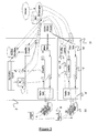
- FIG. 2 illustrates schematically a first aspect of this mobility solution in the context of a 3G network operated by a given network operator.
- This network forms part of an operator "domain" 1.
- Network components illustrated in Figure 2 include an RNC 2 configured to control a plurality of Radio Base Stations (RBSs) 3.
- the network further comprises a General GPRS Support Node (GGSN) 4 that is located within a GPRS core network part of the operator's network.
- the GGSN 4 interconnects the GPRS core network to an IP backbone network 5 within the same operator domain.
- the IP backbone network is in turn connected to the Internet 6.
- DNS Domain Name System
- DNS Domain Name System
- the radio logic 8 is configured to assist with the switching of traffic flows within the RNC 2.
- a client (UE) 9 has already established a PDP context with the GGSN 4, and that, as part of this process, it will have been allocated a client IP address (and will make use of a self-assigned client port number).
- the UE 9 In order to access a data source such as a source of streaming media, the UE 9 will send a DNS query containing a FQDN (identifying a service to be accessed) to the IP backbone network 5 via the established PDP context.
- the query will be routed to the DNS 7 which will (e.g. based on a configured A record) return an IP address mapped to the FQDN.
- the classifier 11 will either route to the correct application, or some routing function will be included in the local service network.]
- the classifier 11 is configured in particular to identify uplink traffic directed to the resolved IP address (returned to the UE by the DNS) and to route that traffic (shown in Figure 2 using the line identified by reference numeral 20) to the application 19 via the packet concentrator 18.
- the downlink packet handler 12 further comprises a packet insert function (marked with a "+" in the Figure) which allows insertion of packets received from the packet route selector 13.
- the UE 9 starts a session with an application 19 within the local service network 17, for example by performing a TCP handshake (using the received IP address and a well known port number such as port 80) including sending an http GET message including the URL of the requested service.
- Signalling traffic is routed to the TCP/IP layer beneath the application 19 by the packet classifier 11 of the uplink packet handler 10.
- the application identifies the requested service based upon the URL and begins streaming media (e.g. from the data cache) to the UE 9 over the local radio link. [The position of selector 13 is set such that the local service network traffic provided by the application 19 is sent over the local link.]
- This system architecture allows a single application to deliver data from multiple caches, e.g. in order to make available multiple streaming television channels.
- the anchoring information or "state" information for the UE 9 is, in this example:
- mappings considered here use the client IP address (and port number) to identify the UE 9
- other identities can alternatively be used, including the International Mobile Subscriber Identity (IMSI).
- IMSI International Mobile Subscriber Identity
- the only requirement on the identity is that it should uniquely identify the client (at least within the operator's domain).
- the radio logic 8 in the source RNC 2 is made aware of the handover and accordingly notifies the local mobility control entity 14.
- the local radio logic 8' informs the local mobility control entity 14' of the handover, and provides to it the client IP address as well as the identity of the source RNC 2.
- the mobility control entity 14 within the source RNC 2 uses these client identifiers to look up the local mobility database 15 and obtain the associated mapping information, namely [Application_dest_IP, application_port, application_protocol, Receiver_Tunnel_IP, Receiver_tunnel_Port, Reciever_tunnel protocol].
- This mapping information (which may include multiple mappings if the client is engaged in multiple sessions with different applications 19 within the local service network 17 of the source RNC 2) is returned to the local mobility control entity 14' within the target RNC 31, which then establishes an IP tunnel between the local interface 16' and the local service network 17 of the source RNC 2.
- the endpoint of the tunnel in the source RNC 2 is defined by [Receiver_Tunnel_IP, Receiver_tunnel_Port, Receiver_tunnel_protocol] whilst the endpoint within the target RNC is defined by a destination IP address and port number of the target RNC 31 [dest_tunnel_IP, dest_tunnel_port, dest_tunnel_protocol].
- a tunnelling protocol such as Layer 2 Tunnelling Protocol may be used to establish the tunnel, although alternative protocols and procedures will be readily apparent to the skilled person.
- the mobility control entity 14 within the source RNC 2 instructs the packet route selector 13 to switch so as to route traffic through the tunnel.
- These packets have as destination address and port number in the outer (tunnelling) header [dest_tunnel_IP, dest_tunnel_port,dest_tunnel_protocol], whilst the destination address and port number in the inner or encapsulated header is [client_IP, client_port, client_protocol].
- the data traffic flow path following handover of the client from the source to the target RNC is of course much longer than the previous local path, traversing as it does two, rather than just one, RNCs.
- the new path is not significantly less efficient than the prior art routing path where the local data source is located above the GGSN, e.g. within the Internet or IP backbone.
- a local routing path will be used for the vast majority of service accesses.
- FIG. 4 is a flow diagram identifying various steps in this procedure. These steps are as follows:
- the mobility database need not be located within the RNC, but may be located outside of the RNC. Indeed, a single, centralised mobility database may be provided within the radio access network, shared by all or a subset of RNCs within the radio access network.
- 3GPP TS 36.300 ["Evolved Universal Terrestrial Radio Access (E-UTRA) and Evolved Universal Terrestrial Radio Access Network (E-UTRAN)"] describes how the radio layer handover procedure is performed without involvement of the Evolved Packet Core (EPC) network.
- EPC Evolved Packet Core
- messages sent to set up the handover are exchanged directly between the radio network control entities, i.e. the eNBs.
- the release of the resources at the source side during the handover completion phase is triggered by the eNB.
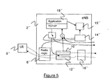
- Figure 5 illustrates schematically a possible eNB architecture, which includes functional components described above with reference to the 3G architecture.
- Figure 7 illustrates schematically an alternative scenario in which the local service network including the application(s) is located within a node 40 that is separate from the source RNC 2.
- a scenario arises, for example, when a UE is being handed over for a second time.
- the sequence of steps 1) to 10) described above with reference to Figure 4 applies in this case, with the difference that at step 9) there is no need to switch the selector in the node 40.
- the application e.g. application 19 in Figure 2
- the uplink packet handler 10 and associated classifier 11 are responsible for routing traffic to the application 19 from the UE 9 based upon destination IP address.
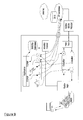
- the application operates as a middlebox, with all traffic between the Internet and the UE being routed via the application. This scenario is illustrated in Figure 8 .
- the classifier 11 in the uplink direction is configured to divert all uplink traffic directed to a given well known port, typically port number 80 for http traffic, to the application 19.
- the application 19 handles traffic addressed to the local service network based upon the destination IP address (and request URL). Other traffic is routed back to the uplink packet handler 10 for forwarding to the Internet.
- An additional classifier 50 is provided within the downlink packet handler 12 and similarly diverts downlink traffic to the application 19 based upon destination port number. The application 19 caches traffic if necessary before returning the traffic to the downlink packet handler 12 for forwarding to the UE 9.
- a second of the selectors 13" is configured in a first position a) to route traffic on the uplink radio link onto the uplink packet bearer for the UE and in a second position b) to route that traffic to the IP backbone via the established tunnel.
- This arrangement requires that, for both TCP/IP stacks, switching of the associated IP packet route selectors 13', 13" is synchronized such that, prior to a handover, both switches are in position a) and following handover both switches are in position b).
- the classifiers are set to the same values in the target node as in the source node.
- the sequence to perform handover is as before.
- the sequence for handover from initial node is shown below with certain required additions.
- the application within the local service network is responsible for registering the anchoring (that is mapping) information for a client into the local mobility database.
- An alternative approach is to trigger the registration of the anchoring information using the TCP-flow set-up message: TCP-syn. This means that anchoring can be done without involving knowledge about the higher layers in the application. It can even be done by the uplink classifier, with the classifier sending a registration message to the mobility database.
- the mobility database may be located at a central node, accessible to multiple radio layer nodes (e.g. RNCs) within the network.
- RNCs radio layer nodes
- a separate mobility controller is implemented within the central database, and supplies the mapping data, on request, to the target RNC.
- the mobility database may also instruct the source RNC to route IP traffic through the tunnel, or a request may subsequently be sent from the target RNC to the source RNC.
- a generic node architecture 100 is illustrated in Figure 10 and comprises a receiver 101 for receiving mapping data from a source RNC following the establishment of an IP flow, at the source RNC, to a client.
- the received mapping data is then stored within a mobility database 102, together with other previously received mappings.
- a mobility controller 103 receives and responds to queries from target RNCs, supplying mapping data extracted from the mobility database.
Landscapes
- Engineering & Computer Science (AREA)
- Computer Networks & Wireless Communication (AREA)
- Signal Processing (AREA)
- Mobile Radio Communication Systems (AREA)
Claims (16)
- Verfahren zum Ermöglichen der Übertragung eines IP-Flusses, wenn ein Client (9) von einem ersten an einen zweiten Funkschichtknoten eines zellularen Kommunikationsnetzes weitergegeben wird, wobei das Verfahren umfasst:Herstellen des IP-Flusses zwischen einem Client (9) und einer Anwendung eines lokalen Dienstnetzes verbunden mit dem oder innerhalb des ersten Funkschichtknoten/s und Senden des IP-Flusses über einen Funkzugangsträger, der sich zwischen dem Client (9) und dem ersten Funkschichtknoten erstreckt;Führen innerhalb einer Mobilitätsdatenbank einer Zuordnung zwischen einer Kennung des Clients (9), einer Anwendungs-IP-Adresse, die mit einer in Verwendung befindlichen Datenquelle für die Anwendung assoziiert ist, und einer IP-Adresse des lokalen Dienstnetzes, wobei die IP-Adresse des lokalen Dienstnetzes eine eindeutige IP-Adresse ist, die es ermöglicht, dass das lokale Dienstnetz, das die Anwendung bereitstellt, extern erreicht wird;Senden vor oder bei Weitergabe des Clients (9) vom ersten Funkschichtknoten an den zweiten Funkschichtknoten einer Anforderung, welche die Client-Kennung umfasst, vom zweiten an den ersten Funkschichtknoten oder einen anderen Knoten, wenn eine zentrale Mobilitätsdatenbank im anderen Knoten unterhalten wird, Verwenden der Client-Kennung, die in der Anforderung enthalten ist, am ersten Funkschichtknoten oder dem anderen Knoten, um die Zuordnung in der Mobilitätsdatenbank oder in der zentralen Mobilitätsdatenbank zu identifizieren, und Senden der Anwendung und der IP-Adresse des lokalen Dienstnetzes vom ersten Funkschichtknoten oder dem anderen Knoten an den zweiten Funkschichtknoten;Empfangen der Anwendung und der IP-Adresse des lokalen Dienstnetzes am zweiten Funkschichtknoten und Verwenden der empfangenen IP-Adresse des lokalen Dienstnetzes am zweiten Funkschichtknoten, um einen Tunnel zwischen dem zweiten Funkschichtknoten und dem lokalen Dienstnetz herzustellen; undUmschalten des IP-Flusses vom Funkzugangsträger auf den Tunnel zur Zustellung an den Client (9) über den zweiten Funkschichtknoten.
- Verfahren nach Anspruch 1 und umfassend ein Einbeziehen in die Zuordnung von Portnummern der Anwendung und des lokalen Dienstnetzes und optional einer IP-Flussprotokoll-Identität und Senden dieser weiteren Informationen zusammen mit den IP-Adressen an den zweiten Funkschichtknoten.
- Verfahren nach Anspruch 1 oder 2, wobei das zellulare Kommunikationsnetz eines von einem terrestrischen UMTS-Funkzugangsnetz, UTRAN, und einem Long Term Evolution-Funkzugangsnetz umfasst, und die ersten und zweiten Funkschichtknoten im ersteren Fall Funknetzsteuerungen sind, und die ersten und zweiten Funkschichtknoten im letzteren Fall eNBs sind.
- Verfahren nach einem der vorhergehenden Ansprüche und umfassend nach der Herstellung des IP-Flusses ein Erkennen von Paketen, die mit dem IP-Fluss assoziiert sind, in einem Uplink-Funkzugangsträger am ersten Funkschichtknoten und Umleiten dieser Pakete zur Anwendung, wobei die Client-Kennung eine Client-IP-Adresse oder eine Client-Portnummer ist.
- Verfahren nach einem der vorhergehenden Ansprüche, wobei der Schritt des Sendens einer Anforderung, welche die Client-Kennung umfasst, vom zweiten an den ersten Funkschichtknoten nach einer Weitergabe der Funkverbindung vom ersten an den zweiten Funkschichtknoten ausgeführt wird, und wobei der Schritt des Umschaltens des IP-Flusses vom ersten Funkzugangsträger auf den Tunnel zur Zustellung an den Client (9) über den zweiten Funkschichtknoten optional durch ein Signal von Funklogik innerhalb des ersten Funkschichtknotens ausgelöst wird, das eine Weitergabe der Funkverbindung bestätigt.
- Verfahren nach Anspruch 5, wobei der Schritt des Sendens einer Anforderung, welche die Client-Kennung umfasst, vom zweiten an den ersten Funkschichtknoten durch Funklogik innerhalb des zweiten Funkschichtknotens ausgelöst wird, die bestimmt, das eine Weitergabe der Funkverbindung abgeschlossen wurde oder ausgeführt wird.
- Verfahren nach einem der Ansprüche 1 bis 4, wobei der Schritt des Sendens einer Anforderung, welche die Client-Kennung umfasst, vom zweiten an den ersten Funkschichtknoten vor einer Weitergabe der Funkverbindung vom ersten an den zweiten Funkschichtknoten, aber nach dem Treffen einer Entscheidung zur Durchführung dieser Weitergabe ausgeführt wird.
- Verfahren nach einem der vorhergehenden Ansprüche, wobei die Tunnelendpunkte durch die IP-Adresse und optional durch die Portnummer des lokalen Dienstnetzes und eine IP-Adresse und optional eine Portnummer des zweiten Funkschichtknotens definiert sind.
- Verfahren nach einem der vorhergehenden Ansprüche, wobei die Mobilitätsdatenbank entweder eine lokale Datenbank innerhalb des ersten Funkschichtknotens oder eine zentrale Datenbank ist, die für mehrere Funkschichtknoten, einschließlich der ersten und zweiten Funkschichtknoten, zentral zugänglich ist.
- Verfahren nach einem der vorhergehenden Ansprüche und umfassend nach der Weitergabe der Funkverbindung ein Identifizieren von Paketen im Uplink-Funkzugangsträger am zweiten Funkschichtknoten, die mit dem IP-Fluss assoziiert sind, basierend auf der empfangenen Anwendungs-IP-Adresse und optional der Anwendungs-Portnummer und Leiten der identifizierten Pakete durch den Tunnel zum lokalen Dienstnetz.
- Verfahren nach einem der vorhergehenden Ansprüche und umfassend ein Umschalten eines oder mehrerer weiterer IP-Flüsse, die am Client (9) abschließen, vom Funkzugangsträger auf den Tunnel zur Zustellung an den Client (9) über den zweiten Funkschichtknoten, wobei der oder jeder weitere IP-Fluss auf einer Netzschicht über dem ersten Funkschichtknoten abgeht.
- Vorrichtung, die so konfiguriert ist, dass sie als ein Funkschichtknoten innerhalb eines zellularen Kommunikationsnetzes funktioniert, wobei die Vorrichtung umfasst:eine IP-Fluss-Steuerung zum Steuern eines IP-Flusses zwischen einem Client (9) und einer Anwendung eines lokalen Dienstnetzes innerhalb oder verbunden mit der Vorrichtung und zum Senden des IP-Flusses über einen Funkzugangsträger, der sich zwischen dem Client (9) und dem ersten Funkschichtknoten erstreckt;eine Datenbanksteuerung zum Führen innerhalb einer Mobilitätsdatenbank einer Zuordnung zwischen einer Kennung des Clients (9), einer Anwendungs-IP-Adresse, die mit einer in Verwendung befindlichen Datenquelle für die Anwendung assoziiert ist, und einer Lokales-Dienstnetz-IP-Adresse des lokalen Dienstnetzes, wobei die IP-Adresse des lokalen Dienstnetzes eine eindeutige IP-Adresse ist, die es ermöglicht, dass das lokale Dienstnetz, das die Anwendung bereitstellt, extern erreicht wird;eine Mobilitätssteuerung, die so konfiguriert ist, dass sie vor der Weitergabe des Clients (9) von der Vorrichtung an einen zweiten Funkschichtknoten eine Anforderung vom zweiten Funkschichtknoten empfängt, welche die Client-Kennung umfasst, die in der Anforderung enthaltene Client-Kennung verwendet, um die Zuordnung in der Mobilitätsdatenbank zu identifizieren, und die Anwendung und die IP-Adresse des lokalen Dienstnetzes an den zweiten Funkschichtkoten sendet;einen Tunnelkonfigurator zum Konfigurieren eines IP-Tunnels zum zweiten Funkschichtknoten; undeinen Switch zum Umschalten des IP-Flusses vom Funkzugangsträger auf den Tunnel zur Zustellung an den Client (9) über den zweiten Funkschichtknoten.
- Vorrichtung nach Anspruch 12, wobei die Vorrichtung die Mobilitätsdatenbank umfasst.
- Vorrichtung nach Anspruch 12 oder 13, wobei die Vorrichtung so konfiguriert ist, dass sie als eines von Folgendem funktioniert:einer Funknetzsteuerung innerhalb eines terrestrischen UMTS-Funkzugangsnetzes, UTRA, oder als ein erweiterter Knoten B innerhalb eines Long Term Evolution-Funkzugangsnetzes; undeiner Middlebox, die einen IP-Fluss, der ein IP-Kernnetz des zellularen Kommunikationsnetzes durchquert, zu einer Anwendung des lokalen Dienstnetzes leitet, und einen weiteren Switch zum Umschalten des weiteren IP-Flusses vom Funkzugangsträger auf den Tunnel zur Zustellung an den Client über den zweiten Funkschichtknoten umfasst, wobei die Datenbanksteuerung optional so konfiguriert ist, dass sie innerhalb der Mobilitätsdatenbank eine Kennung des Clients (9), eine IP-Adresse der Anwendung, zu welcher der das IP-Kernnetz durchquerende IP-Fluss geleitet wird, und eine IP-Adresse des lokalen Dienstnetzes führt, und die Mobilitätssteuerung so konfiguriert ist, dass sie auch diese weitere Zuordnung vor oder bei der Weitergabe für den zweiten Funkschichtknoten bereitstellt.
- Vorrichtung nach einem der Ansprüche 12 bis 14, wobei die Datenbanksteuerung so konfiguriert ist, dass sie in die Zuordnung(en) Portnummern der Anwendung und des lokalen Dienstnetzes und optional eine IP-Flussprotokoll-Identität einbezieht, und die Mobilitätssteuerung so konfiguriert ist, dass sie diese weiteren Informationen zusammen mit den IP-Adressen an den zweiten Funkschichtknoten sendet.
- Vorrichtung, die so konfiguriert ist, dass innerhalb eines zellularen Kommunikationsnetzes funktioniert, wobei die Vorrichtung umfasst:einen Empfänger zum Empfangen von einem ersten Funkschichtknoten einer Zuordnung zwischen einer Kennung eines Clients (9), der mit dem Funkschichtknoten assoziiert ist, einer Anwendungs-IP-Adresse, die mit einer in Verwendung befindlichen Datenquelle für eine Anwendung assoziiert ist, die den IP-Fluss an den Client (9) zustellt, und einer Lokales-Dienstnetz-IP-Adresse eines lokalen Dienstnetzes, wobei die IP-Adresse des lokalen Dienstnetzes eine eindeutige IP-Adresse ist, die es ermöglicht, dass das lokale Dienstnetz, das die Anwendung bereitstellt, extern erreicht wird;eine Mobilitätsdatenbank, welche die empfangene Zuordnung aufzeichnet; undeine Mobilitätssteuerung, die so konfiguriert ist, dass sie vor der Weitergabe des Clients (9) vom ersten Funkschichtknoten an einen zweiten Funkschichtknoten eine Anforderung vom zweiten Funkschichtknoten empfängt, welche die Client-Kennung umfasst, die in der Anforderung enthaltene Client-Kennung verwendet, um die Zuordnung in der Mobilitätsdatenbank zu identifizieren, und die Anwendung und die IP-Adresse des lokalen Dienstnetzes an den zweiten Funkschichtkoten sendet.
Applications Claiming Priority (1)
| Application Number | Priority Date | Filing Date | Title |
|---|---|---|---|
| PCT/EP2011/054978 WO2012130308A1 (en) | 2011-03-31 | 2011-03-31 | Cellular network mobility |
Publications (2)
| Publication Number | Publication Date |
|---|---|
| EP2702802A1 EP2702802A1 (de) | 2014-03-05 |
| EP2702802B1 true EP2702802B1 (de) | 2015-05-06 |
Family
ID=44625616
Family Applications (1)
| Application Number | Title | Priority Date | Filing Date |
|---|---|---|---|
| EP20110711560 Not-in-force EP2702802B1 (de) | 2011-03-31 | 2011-03-31 | Mobilfunknetzmobilität |
Country Status (3)
| Country | Link |
|---|---|
| US (1) | US9014142B2 (de) |
| EP (1) | EP2702802B1 (de) |
| WO (1) | WO2012130308A1 (de) |
Families Citing this family (8)
| Publication number | Priority date | Publication date | Assignee | Title |
|---|---|---|---|---|
| CN103621141A (zh) * | 2011-06-28 | 2014-03-05 | 京瓷株式会社 | 通信控制方法和家庭基站 |
| US9503935B2 (en) * | 2013-01-28 | 2016-11-22 | Blackberry Limited | Handover mechanism in cellular networks |
| US9521600B2 (en) | 2013-01-28 | 2016-12-13 | Blackberry Limited | Handover mechanism in cellular networks |
| US9820316B2 (en) * | 2013-03-15 | 2017-11-14 | Aerohive Networks, Inc. | Preventing asymmetric routing using network tunneling |
| EP2989849B1 (de) | 2013-04-23 | 2019-06-05 | LG Electronics Inc. | Verfahren und vorrichtung zur übertragung von inaktivitätsanzeigen in einem drahtloskommunikationssystem |
| EP3005823B1 (de) | 2013-05-31 | 2017-01-11 | Telefonaktiebolaget LM Ericsson (publ) | Service schicht zu steuern bewusst steuermeldung in einem kommunikationsnetz |
| US10117287B2 (en) * | 2014-08-26 | 2018-10-30 | Nokia Of America Corporation | Method and apparatus for improved dual connectivity |
| EP3405877B1 (de) * | 2016-01-22 | 2022-09-21 | Nokia Solutions and Networks Oy | Anwendungsverlagerung zwischen clouds |
Family Cites Families (8)
| Publication number | Priority date | Publication date | Assignee | Title |
|---|---|---|---|---|
| US7532596B2 (en) * | 2002-04-26 | 2009-05-12 | Nokia Corporation | Optimized information transfer associated with relocation of an IP session in a mobile communications system |
| DE60220808D1 (de) * | 2002-12-20 | 2007-08-02 | Motorola Inc | Verfahren und Vorrichtung zur Datenstrombehandlung in mobilem IP |
| US8489096B2 (en) * | 2006-06-01 | 2013-07-16 | Nokia Corporation | Inter-access handover with access specific policy control functions |
| US8867486B2 (en) | 2009-04-17 | 2014-10-21 | Qualcomm Incorporated | Wireless data communications employing IP flow mobility |
| US8428601B2 (en) * | 2009-05-07 | 2013-04-23 | Airvana Network Solutions, Inc. | Wireless network inter-technology handoffs |
| US8942167B2 (en) * | 2009-05-14 | 2015-01-27 | Avaya Inc. | Methods, apparatus and computer readable medium for seamless internet protocol multicast connectivity in unified networks |
| JPWO2011001594A1 (ja) * | 2009-06-29 | 2012-12-10 | パナソニック株式会社 | リダイレクション方法、リダイレクションシステム、モバイルノード、ホームエージェント及び代理ノード |
| TWI548237B (zh) * | 2011-02-24 | 2016-09-01 | 內數位專利控股公司 | 穩定本地分匯概念及使用 |
-
2011
- 2011-03-31 EP EP20110711560 patent/EP2702802B1/de not_active Not-in-force
- 2011-03-31 WO PCT/EP2011/054978 patent/WO2012130308A1/en not_active Ceased
- 2011-03-31 US US14/007,555 patent/US9014142B2/en not_active Expired - Fee Related
Also Published As
| Publication number | Publication date |
|---|---|
| US9014142B2 (en) | 2015-04-21 |
| WO2012130308A1 (en) | 2012-10-04 |
| EP2702802A1 (de) | 2014-03-05 |
| US20140023042A1 (en) | 2014-01-23 |
Similar Documents
| Publication | Publication Date | Title |
|---|---|---|
| US11818603B2 (en) | Packet duplication | |
| EP2702802B1 (de) | Mobilfunknetzmobilität | |
| EP3844922B1 (de) | Detektion von verkehr über quick udp internet connections (quic) in einem telekommunikationsnetzwerk zwischen einem benutzergerät (ue) und einem inhaltsanbieter (cp) | |
| CN105873133B (zh) | 双连接架构下支持业务本地分流的方法及设备 | |
| US11129054B2 (en) | Methods, systems and devices for supporting local breakout in small cell architecture | |
| US10390259B2 (en) | Data forwarding in a mobile communications network system with centralized gateway apparatus controlling distributed gateway elements | |
| US10104541B2 (en) | Method and apparatus for establishing user plane bearer | |
| US20160174285A1 (en) | Method for maintaining service continuity in heterogeneous communications system | |
| US10098042B2 (en) | MME, local server, MME-local server interface, and data transmission method for optimized data path in LTE network | |
| US8767728B2 (en) | Tunnel gateway managed caching architecture | |
| US20210029586A1 (en) | Methods and system for offloading data traffic | |
| US20170272990A1 (en) | Methods and apparatus for wireless connection management | |
| WO2017219355A1 (zh) | 多连接通信方法和设备 | |
| CN105992393A (zh) | 建立辅基站的方法及设备 | |
| EP2724563B1 (de) | Zwischenspeicherung über eine schnittstelle zwischen einem funkzugangsnetz und einem core-netzwerk | |
| WO2018188728A1 (en) | Handover with no or limited mme involvement | |
| US9277457B2 (en) | Efficient data delivery in cellular networks | |
| EP3694252B1 (de) | Verfahren und vorrichtung zur zellumschaltung |
Legal Events
| Date | Code | Title | Description |
|---|---|---|---|
| PUAI | Public reference made under article 153(3) epc to a published international application that has entered the european phase |
Free format text: ORIGINAL CODE: 0009012 |
|
| 17P | Request for examination filed |
Effective date: 20130827 |
|
| AK | Designated contracting states |
Kind code of ref document: A1 Designated state(s): AL AT BE BG CH CY CZ DE DK EE ES FI FR GB GR HR HU IE IS IT LI LT LU LV MC MK MT NL NO PL PT RO RS SE SI SK SM TR |
|
| DAX | Request for extension of the european patent (deleted) | ||
| GRAP | Despatch of communication of intention to grant a patent |
Free format text: ORIGINAL CODE: EPIDOSNIGR1 |
|
| INTG | Intention to grant announced |
Effective date: 20141114 |
|
| GRAS | Grant fee paid |
Free format text: ORIGINAL CODE: EPIDOSNIGR3 |
|
| GRAA | (expected) grant |
Free format text: ORIGINAL CODE: 0009210 |
|
| AK | Designated contracting states |
Kind code of ref document: B1 Designated state(s): AL AT BE BG CH CY CZ DE DK EE ES FI FR GB GR HR HU IE IS IT LI LT LU LV MC MK MT NL NO PL PT RO RS SE SI SK SM TR |
|
| REG | Reference to a national code |
Ref country code: GB Ref legal event code: FG4D |
|
| REG | Reference to a national code |
Ref country code: CH Ref legal event code: EP |
|
| REG | Reference to a national code |
Ref country code: IE Ref legal event code: FG4D |
|
| REG | Reference to a national code |
Ref country code: AT Ref legal event code: REF Ref document number: 726423 Country of ref document: AT Kind code of ref document: T Effective date: 20150615 |
|
| REG | Reference to a national code |
Ref country code: DE Ref legal event code: R096 Ref document number: 602011016283 Country of ref document: DE Effective date: 20150618 |
|
| REG | Reference to a national code |
Ref country code: NL Ref legal event code: T3 |
|
| REG | Reference to a national code |
Ref country code: AT Ref legal event code: MK05 Ref document number: 726423 Country of ref document: AT Kind code of ref document: T Effective date: 20150506 |
|
| REG | Reference to a national code |
Ref country code: LT Ref legal event code: MG4D |
|
| PG25 | Lapsed in a contracting state [announced via postgrant information from national office to epo] |
Ref country code: PT Free format text: LAPSE BECAUSE OF FAILURE TO SUBMIT A TRANSLATION OF THE DESCRIPTION OR TO PAY THE FEE WITHIN THE PRESCRIBED TIME-LIMIT Effective date: 20150907 Ref country code: LT Free format text: LAPSE BECAUSE OF FAILURE TO SUBMIT A TRANSLATION OF THE DESCRIPTION OR TO PAY THE FEE WITHIN THE PRESCRIBED TIME-LIMIT Effective date: 20150506 Ref country code: NO Free format text: LAPSE BECAUSE OF FAILURE TO SUBMIT A TRANSLATION OF THE DESCRIPTION OR TO PAY THE FEE WITHIN THE PRESCRIBED TIME-LIMIT Effective date: 20150806 Ref country code: ES Free format text: LAPSE BECAUSE OF FAILURE TO SUBMIT A TRANSLATION OF THE DESCRIPTION OR TO PAY THE FEE WITHIN THE PRESCRIBED TIME-LIMIT Effective date: 20150506 Ref country code: FI Free format text: LAPSE BECAUSE OF FAILURE TO SUBMIT A TRANSLATION OF THE DESCRIPTION OR TO PAY THE FEE WITHIN THE PRESCRIBED TIME-LIMIT Effective date: 20150506 Ref country code: HR Free format text: LAPSE BECAUSE OF FAILURE TO SUBMIT A TRANSLATION OF THE DESCRIPTION OR TO PAY THE FEE WITHIN THE PRESCRIBED TIME-LIMIT Effective date: 20150506 |
|
| PG25 | Lapsed in a contracting state [announced via postgrant information from national office to epo] |
Ref country code: LV Free format text: LAPSE BECAUSE OF FAILURE TO SUBMIT A TRANSLATION OF THE DESCRIPTION OR TO PAY THE FEE WITHIN THE PRESCRIBED TIME-LIMIT Effective date: 20150506 Ref country code: IS Free format text: LAPSE BECAUSE OF FAILURE TO SUBMIT A TRANSLATION OF THE DESCRIPTION OR TO PAY THE FEE WITHIN THE PRESCRIBED TIME-LIMIT Effective date: 20150906 Ref country code: RS Free format text: LAPSE BECAUSE OF FAILURE TO SUBMIT A TRANSLATION OF THE DESCRIPTION OR TO PAY THE FEE WITHIN THE PRESCRIBED TIME-LIMIT Effective date: 20150506 Ref country code: AT Free format text: LAPSE BECAUSE OF FAILURE TO SUBMIT A TRANSLATION OF THE DESCRIPTION OR TO PAY THE FEE WITHIN THE PRESCRIBED TIME-LIMIT Effective date: 20150506 Ref country code: BG Free format text: LAPSE BECAUSE OF FAILURE TO SUBMIT A TRANSLATION OF THE DESCRIPTION OR TO PAY THE FEE WITHIN THE PRESCRIBED TIME-LIMIT Effective date: 20150806 Ref country code: GR Free format text: LAPSE BECAUSE OF FAILURE TO SUBMIT A TRANSLATION OF THE DESCRIPTION OR TO PAY THE FEE WITHIN THE PRESCRIBED TIME-LIMIT Effective date: 20150807 |
|
| PG25 | Lapsed in a contracting state [announced via postgrant information from national office to epo] |
Ref country code: EE Free format text: LAPSE BECAUSE OF FAILURE TO SUBMIT A TRANSLATION OF THE DESCRIPTION OR TO PAY THE FEE WITHIN THE PRESCRIBED TIME-LIMIT Effective date: 20150506 Ref country code: DK Free format text: LAPSE BECAUSE OF FAILURE TO SUBMIT A TRANSLATION OF THE DESCRIPTION OR TO PAY THE FEE WITHIN THE PRESCRIBED TIME-LIMIT Effective date: 20150506 |
|
| REG | Reference to a national code |
Ref country code: DE Ref legal event code: R097 Ref document number: 602011016283 Country of ref document: DE |
|
| PG25 | Lapsed in a contracting state [announced via postgrant information from national office to epo] |
Ref country code: CZ Free format text: LAPSE BECAUSE OF FAILURE TO SUBMIT A TRANSLATION OF THE DESCRIPTION OR TO PAY THE FEE WITHIN THE PRESCRIBED TIME-LIMIT Effective date: 20150506 Ref country code: RO Free format text: LAPSE BECAUSE OF NON-PAYMENT OF DUE FEES Effective date: 20150506 Ref country code: SK Free format text: LAPSE BECAUSE OF FAILURE TO SUBMIT A TRANSLATION OF THE DESCRIPTION OR TO PAY THE FEE WITHIN THE PRESCRIBED TIME-LIMIT Effective date: 20150506 Ref country code: PL Free format text: LAPSE BECAUSE OF FAILURE TO SUBMIT A TRANSLATION OF THE DESCRIPTION OR TO PAY THE FEE WITHIN THE PRESCRIBED TIME-LIMIT Effective date: 20150506 |
|
| PLBE | No opposition filed within time limit |
Free format text: ORIGINAL CODE: 0009261 |
|
| STAA | Information on the status of an ep patent application or granted ep patent |
Free format text: STATUS: NO OPPOSITION FILED WITHIN TIME LIMIT |
|
| 26N | No opposition filed |
Effective date: 20160209 |
|
| PG25 | Lapsed in a contracting state [announced via postgrant information from national office to epo] |
Ref country code: IT Free format text: LAPSE BECAUSE OF FAILURE TO SUBMIT A TRANSLATION OF THE DESCRIPTION OR TO PAY THE FEE WITHIN THE PRESCRIBED TIME-LIMIT Effective date: 20150506 |
|
| PG25 | Lapsed in a contracting state [announced via postgrant information from national office to epo] |
Ref country code: SI Free format text: LAPSE BECAUSE OF FAILURE TO SUBMIT A TRANSLATION OF THE DESCRIPTION OR TO PAY THE FEE WITHIN THE PRESCRIBED TIME-LIMIT Effective date: 20150506 |
|
| PG25 | Lapsed in a contracting state [announced via postgrant information from national office to epo] |
Ref country code: BE Free format text: LAPSE BECAUSE OF FAILURE TO SUBMIT A TRANSLATION OF THE DESCRIPTION OR TO PAY THE FEE WITHIN THE PRESCRIBED TIME-LIMIT Effective date: 20150506 |
|
| PG25 | Lapsed in a contracting state [announced via postgrant information from national office to epo] |
Ref country code: MC Free format text: LAPSE BECAUSE OF FAILURE TO SUBMIT A TRANSLATION OF THE DESCRIPTION OR TO PAY THE FEE WITHIN THE PRESCRIBED TIME-LIMIT Effective date: 20150506 Ref country code: LU Free format text: LAPSE BECAUSE OF FAILURE TO SUBMIT A TRANSLATION OF THE DESCRIPTION OR TO PAY THE FEE WITHIN THE PRESCRIBED TIME-LIMIT Effective date: 20160331 |
|
| REG | Reference to a national code |
Ref country code: CH Ref legal event code: PL |
|
| REG | Reference to a national code |
Ref country code: IE Ref legal event code: MM4A |
|
| REG | Reference to a national code |
Ref country code: FR Ref legal event code: ST Effective date: 20161130 |
|
| PG25 | Lapsed in a contracting state [announced via postgrant information from national office to epo] |
Ref country code: FR Free format text: LAPSE BECAUSE OF NON-PAYMENT OF DUE FEES Effective date: 20160331 Ref country code: LI Free format text: LAPSE BECAUSE OF NON-PAYMENT OF DUE FEES Effective date: 20160331 Ref country code: IE Free format text: LAPSE BECAUSE OF NON-PAYMENT OF DUE FEES Effective date: 20160331 Ref country code: CH Free format text: LAPSE BECAUSE OF NON-PAYMENT OF DUE FEES Effective date: 20160331 |
|
| PG25 | Lapsed in a contracting state [announced via postgrant information from national office to epo] |
Ref country code: SE Free format text: LAPSE BECAUSE OF FAILURE TO SUBMIT A TRANSLATION OF THE DESCRIPTION OR TO PAY THE FEE WITHIN THE PRESCRIBED TIME-LIMIT Effective date: 20150506 |
|
| PG25 | Lapsed in a contracting state [announced via postgrant information from national office to epo] |
Ref country code: MT Free format text: LAPSE BECAUSE OF FAILURE TO SUBMIT A TRANSLATION OF THE DESCRIPTION OR TO PAY THE FEE WITHIN THE PRESCRIBED TIME-LIMIT Effective date: 20150506 |
|
| PG25 | Lapsed in a contracting state [announced via postgrant information from national office to epo] |
Ref country code: CY Free format text: LAPSE BECAUSE OF FAILURE TO SUBMIT A TRANSLATION OF THE DESCRIPTION OR TO PAY THE FEE WITHIN THE PRESCRIBED TIME-LIMIT Effective date: 20150506 Ref country code: SM Free format text: LAPSE BECAUSE OF FAILURE TO SUBMIT A TRANSLATION OF THE DESCRIPTION OR TO PAY THE FEE WITHIN THE PRESCRIBED TIME-LIMIT Effective date: 20150506 Ref country code: HU Free format text: LAPSE BECAUSE OF FAILURE TO SUBMIT A TRANSLATION OF THE DESCRIPTION OR TO PAY THE FEE WITHIN THE PRESCRIBED TIME-LIMIT; INVALID AB INITIO Effective date: 20110331 |
|
| PG25 | Lapsed in a contracting state [announced via postgrant information from national office to epo] |
Ref country code: TR Free format text: LAPSE BECAUSE OF FAILURE TO SUBMIT A TRANSLATION OF THE DESCRIPTION OR TO PAY THE FEE WITHIN THE PRESCRIBED TIME-LIMIT Effective date: 20150506 Ref country code: MK Free format text: LAPSE BECAUSE OF FAILURE TO SUBMIT A TRANSLATION OF THE DESCRIPTION OR TO PAY THE FEE WITHIN THE PRESCRIBED TIME-LIMIT Effective date: 20150506 |
|
| PG25 | Lapsed in a contracting state [announced via postgrant information from national office to epo] |
Ref country code: AL Free format text: LAPSE BECAUSE OF FAILURE TO SUBMIT A TRANSLATION OF THE DESCRIPTION OR TO PAY THE FEE WITHIN THE PRESCRIBED TIME-LIMIT Effective date: 20150506 |
|
| PGFP | Annual fee paid to national office [announced via postgrant information from national office to epo] |
Ref country code: DE Payment date: 20190327 Year of fee payment: 9 |
|
| PGFP | Annual fee paid to national office [announced via postgrant information from national office to epo] |
Ref country code: NL Payment date: 20190326 Year of fee payment: 9 |
|
| PGFP | Annual fee paid to national office [announced via postgrant information from national office to epo] |
Ref country code: GB Payment date: 20190404 Year of fee payment: 9 |
|
| REG | Reference to a national code |
Ref country code: DE Ref legal event code: R119 Ref document number: 602011016283 Country of ref document: DE |
|
| REG | Reference to a national code |
Ref country code: NL Ref legal event code: MM Effective date: 20200401 |
|
| PG25 | Lapsed in a contracting state [announced via postgrant information from national office to epo] |
Ref country code: NL Free format text: LAPSE BECAUSE OF NON-PAYMENT OF DUE FEES Effective date: 20200401 |
|
| PG25 | Lapsed in a contracting state [announced via postgrant information from national office to epo] |
Ref country code: DE Free format text: LAPSE BECAUSE OF NON-PAYMENT OF DUE FEES Effective date: 20201001 |
|
| GBPC | Gb: european patent ceased through non-payment of renewal fee |
Effective date: 20200331 |
|
| PG25 | Lapsed in a contracting state [announced via postgrant information from national office to epo] |
Ref country code: GB Free format text: LAPSE BECAUSE OF NON-PAYMENT OF DUE FEES Effective date: 20200331 |