EP2703192A1 - Dispositif de contrôle de la pression d'air d'un pneu - Google Patents
Dispositif de contrôle de la pression d'air d'un pneu Download PDFInfo
- Publication number
- EP2703192A1 EP2703192A1 EP12777592.2A EP12777592A EP2703192A1 EP 2703192 A1 EP2703192 A1 EP 2703192A1 EP 12777592 A EP12777592 A EP 12777592A EP 2703192 A1 EP2703192 A1 EP 2703192A1
- Authority
- EP
- European Patent Office
- Prior art keywords
- wheel
- rotational position
- sensor
- tire
- tpms
- Prior art date
- Legal status (The legal status is an assumption and is not a legal conclusion. Google has not performed a legal analysis and makes no representation as to the accuracy of the status listed.)
- Granted
Links
Images



Classifications
-
- B—PERFORMING OPERATIONS; TRANSPORTING
- B60—VEHICLES IN GENERAL
- B60C—VEHICLE TYRES; TYRE INFLATION; TYRE CHANGING; CONNECTING VALVES TO INFLATABLE ELASTIC BODIES IN GENERAL; DEVICES OR ARRANGEMENTS RELATED TO TYRES
- B60C23/00—Devices for measuring, signalling, controlling, or distributing tyre pressure or temperature, specially adapted for mounting on vehicles; Arrangement of tyre inflating devices on vehicles, e.g. of pumps or of tanks; Tyre cooling arrangements
- B60C23/02—Signalling devices actuated by tyre pressure
- B60C23/04—Signalling devices actuated by tyre pressure mounted on the wheel or tyre
- B60C23/0408—Signalling devices actuated by tyre pressure mounted on the wheel or tyre transmitting the signals by non-mechanical means from the wheel or tyre to a vehicle body mounted receiver
- B60C23/0415—Automatically identifying wheel mounted units, e.g. after replacement or exchange of wheels
-
- B—PERFORMING OPERATIONS; TRANSPORTING
- B60—VEHICLES IN GENERAL
- B60C—VEHICLE TYRES; TYRE INFLATION; TYRE CHANGING; CONNECTING VALVES TO INFLATABLE ELASTIC BODIES IN GENERAL; DEVICES OR ARRANGEMENTS RELATED TO TYRES
- B60C23/00—Devices for measuring, signalling, controlling, or distributing tyre pressure or temperature, specially adapted for mounting on vehicles; Arrangement of tyre inflating devices on vehicles, e.g. of pumps or of tanks; Tyre cooling arrangements
- B60C23/02—Signalling devices actuated by tyre pressure
-
- B—PERFORMING OPERATIONS; TRANSPORTING
- B60—VEHICLES IN GENERAL
- B60C—VEHICLE TYRES; TYRE INFLATION; TYRE CHANGING; CONNECTING VALVES TO INFLATABLE ELASTIC BODIES IN GENERAL; DEVICES OR ARRANGEMENTS RELATED TO TYRES
- B60C23/00—Devices for measuring, signalling, controlling, or distributing tyre pressure or temperature, specially adapted for mounting on vehicles; Arrangement of tyre inflating devices on vehicles, e.g. of pumps or of tanks; Tyre cooling arrangements
- B60C23/02—Signalling devices actuated by tyre pressure
- B60C23/04—Signalling devices actuated by tyre pressure mounted on the wheel or tyre
- B60C23/0408—Signalling devices actuated by tyre pressure mounted on the wheel or tyre transmitting the signals by non-mechanical means from the wheel or tyre to a vehicle body mounted receiver
- B60C23/0415—Automatically identifying wheel mounted units, e.g. after replacement or exchange of wheels
- B60C23/0416—Automatically identifying wheel mounted units, e.g. after replacement or exchange of wheels allocating a corresponding wheel position on vehicle, e.g. front/left or rear/right
-
- B—PERFORMING OPERATIONS; TRANSPORTING
- B60—VEHICLES IN GENERAL
- B60C—VEHICLE TYRES; TYRE INFLATION; TYRE CHANGING; CONNECTING VALVES TO INFLATABLE ELASTIC BODIES IN GENERAL; DEVICES OR ARRANGEMENTS RELATED TO TYRES
- B60C23/00—Devices for measuring, signalling, controlling, or distributing tyre pressure or temperature, specially adapted for mounting on vehicles; Arrangement of tyre inflating devices on vehicles, e.g. of pumps or of tanks; Tyre cooling arrangements
- B60C23/02—Signalling devices actuated by tyre pressure
- B60C23/04—Signalling devices actuated by tyre pressure mounted on the wheel or tyre
-
- B—PERFORMING OPERATIONS; TRANSPORTING
- B60—VEHICLES IN GENERAL
- B60C—VEHICLE TYRES; TYRE INFLATION; TYRE CHANGING; CONNECTING VALVES TO INFLATABLE ELASTIC BODIES IN GENERAL; DEVICES OR ARRANGEMENTS RELATED TO TYRES
- B60C23/00—Devices for measuring, signalling, controlling, or distributing tyre pressure or temperature, specially adapted for mounting on vehicles; Arrangement of tyre inflating devices on vehicles, e.g. of pumps or of tanks; Tyre cooling arrangements
- B60C23/02—Signalling devices actuated by tyre pressure
- B60C23/04—Signalling devices actuated by tyre pressure mounted on the wheel or tyre
- B60C23/0486—Signalling devices actuated by tyre pressure mounted on the wheel or tyre comprising additional sensors in the wheel or tyre mounted monitoring device, e.g. movement sensors, microphones or earth magnetic field sensors
- B60C23/0488—Movement sensor, e.g. for sensing angular speed, acceleration or centripetal force
-
- B—PERFORMING OPERATIONS; TRANSPORTING
- B60—VEHICLES IN GENERAL
- B60C—VEHICLE TYRES; TYRE INFLATION; TYRE CHANGING; CONNECTING VALVES TO INFLATABLE ELASTIC BODIES IN GENERAL; DEVICES OR ARRANGEMENTS RELATED TO TYRES
- B60C23/00—Devices for measuring, signalling, controlling, or distributing tyre pressure or temperature, specially adapted for mounting on vehicles; Arrangement of tyre inflating devices on vehicles, e.g. of pumps or of tanks; Tyre cooling arrangements
- B60C23/02—Signalling devices actuated by tyre pressure
- B60C23/04—Signalling devices actuated by tyre pressure mounted on the wheel or tyre
- B60C23/0486—Signalling devices actuated by tyre pressure mounted on the wheel or tyre comprising additional sensors in the wheel or tyre mounted monitoring device, e.g. movement sensors, microphones or earth magnetic field sensors
- B60C23/0489—Signalling devices actuated by tyre pressure mounted on the wheel or tyre comprising additional sensors in the wheel or tyre mounted monitoring device, e.g. movement sensors, microphones or earth magnetic field sensors for detecting the actual angular position of the monitoring device while the wheel is turning
-
- G—PHYSICS
- G01—MEASURING; TESTING
- G01L—MEASURING FORCE, STRESS, TORQUE, WORK, MECHANICAL POWER, MECHANICAL EFFICIENCY, OR FLUID PRESSURE
- G01L17/00—Devices or apparatus for measuring tyre pressure or the pressure in other inflated bodies
-
- G—PHYSICS
- G08—SIGNALLING
- G08C—TRANSMISSION SYSTEMS FOR MEASURED VALUES, CONTROL OR SIMILAR SIGNALS
- G08C17/00—Arrangements for transmitting signals characterised by the use of a wireless electrical link
- G08C17/02—Arrangements for transmitting signals characterised by the use of a wireless electrical link using a radio link
Definitions
- the present invention related to a tire air pressure monitor device.
- a transmitter sends a wireless signal at a constant, prescribed rotational position.
- the rotational positions of respective wheels are detected.
- the wheel position associated with a transmitter corresponding to the rotational position that is best in synchronization with the output period of the wireless signal among the rotational positions of the wheels is determined as the position of the wheel (wheel position) with which that transmitter is associated.
- Patent Document 1 Japanese Patent Application Publication No. 2010-122023
- the rotational position of a transmitter is determined from the output value of an acceleration sensor, and a wireless signal is output at the time when the output value of the acceleration sensor assumes the prescribed value.
- a braking control such as an ABS control
- the transmitter is likely to determine the rotational position erroneously and output a wireless signal at a rotational position different from the prescribed rotational position. Consequently, because of the determination of the wheel position of the transmitter based on the erroneous data on the rotational position, the determination of the wheel position is likely to be delayed.
- the purpose or objective of the present invention is to provide a tire air or pneumatic pressure monitoring device that may suppress delay in the determination of wheel position.
- the rotational position associated with each wheel corresponding to that wireless signal will not be detected. Therefore, the erroneous data of the rotational position for determination of the wheel position is prevented from being used so that a dely in the wheel position determination may be suppressed.
- FIG. 1 is a configuration diagram illustrating a tire air or pneumatic pressure monitoring device in a first embodiment.
- the end letters annexed to each reference sign is intended to indicate as follows: FL stands for the left front wheel, FR stands for the right front wheel, RL stands for the left rear wheel, and RR stands for the right rear wheel, respectively.
- FL stands for the left front wheel
- FR stands for the right front wheel
- RL stands for the left rear wheel
- RR stands for the right rear wheel
- the tire pneumatic pressure monitoring device in the first embodiment is provided with a TPMS (tire pressure monitoring system) sensors 2, a receiver 3, a TPMS control unit (TPMSCU) 4, a display 5, and wheel speed sensors 8.
- TPMS tire pressure monitoring system
- the TPMS sensor 2 is installed on each of the wheels 1, and the receiver 3, the TPMSCU 4, the display 5 and the wheel speed sensors 8 are arranged on the side of the vehicle body.
- the TPMS sensor 2 is installed at the position of an air valve (not shown in the figure) of each tire.
- FIG. 2 is a diagram illustrating the configuration of the TPMS sensor 2.
- the TPMS sensor 2 comprises a pressure sensor (a tire pneumatic pressure detecting mechanism) 2 a , an acceleration sensor (G sensor) 2 b , a sensor control unit (sensor CU) 2 c , a transmitter 2 d , and a button battery 2 e .
- the pressure sensor 2 a detects the pneumatic pressure [kPa] of the tire.
- the G sensor 2 b detects the acceleration in the centrifugal direction [G] acting on the tire.
- the sensor CU 2 c operates under the power supplied from the button battery 2 e , and the TPMS data containing the pneumatic pressure information of the tire detected by the pressure sensor 2 a and the sensor ID (the identification information) is sent as a wireless signal from the transmitter 2 d .
- the sensor IDs are defined by 1 to 4.
- the sensor CU 2 c compares the acceleration in the centrifugal direction detected by the G sensor 2 b with a preset threshold for determination of a vehicle running state. When the acceleration in the centrifugal direction is less than the running determination threshold, a determination is made that the vehicle is being stopped or stationary, so that transmission of the TPMS data is stopped. On the other hand, when the acceleration in the centrifugal direction exceeds the running determination threshold, a determination is made that the vehicle is running, and the TPMS data will be transmitted at a prescribed timing
- the receiver 3 receives the wireless signals output from each TPMS sensor 2 to decode and output to the TPMSCU 4.
- the TPMSCU 4 reads respective TPMS data, based on the sensor ID in the TPMS data and with reference to the corresponce relationship between each of the sensor IDs and the wheel positions stored in a nonvolatile memory 4 d (see FIG. 3 ), the TPMSCU4 determines to which wheel position the TPMS data is corresponding and indicates on the display 5 a tire air pressure contained in the TPMS data as the pneumatic pressure of the corresponding wheel position.
- the pneumatic pressure of a tire becomes below a lower limit threshold, the decrease in the pneumatic pressure is notified by a change in the display color, in flashing on the display, by an alarm sound, or the like.
- the ABSCU 6 Based on the wheel speed chain of pulses from each of wheel speed sensors 8, the ABSCU 6 detects the wheel speed of each wheel 1 , respectively. When a certain wheel has a locking tendency, an ABS actuator not shown in the figure is operated to adjust or maintain a wheel cylinder pressure of the corresponding wheel to suppress the locking tendency. In this way, the anti-skid brake control (ABS) is carried out.
- the ABSCU 6 outputs the count value of the wheel speed pulses to the CAN communication line 7 at every prescribed period of time (e.g., 20 msec).
- the wheel speed sensor comprises a gear-shaped rotor rotating in synchronization with the wheel 1, and both a permanent magnet and a coil arranged on the side of the vehicle body and facing the outer periphery of the rotor. As the rotor rotates, the concave-convex or corrugated surface of the rotor crosses the magnetic field formed on the periphery of the wheel speed sensor 8, so that the magnetic flux density varies to generate an electromotive force in the coil, and such a variation in the voltage is output as the wheel speed pulse signal to the ABSCU 6.
- the ABSCU 6 executes a vehicle behavior stabilization control, a brake traction control, and a brake LSD control as a control to control the wheel cylinder pressure of the wheel 1. More specifically, by the vehicle behavior stabilization control, the wheel is imparted with a braking force to suppress an over-steering tendency or under-steering tendency of the vehicle to secure a vehicle running stability.
- the brake traction control a road gripping force of the tire will be increased by suppressing idle rotation or spin of a drive wheel, when one side of the drive wheels slips such as on a low ⁇ road and the like.
- a differential is limited by using a brake.
- ABSCU6 outputs a control flag signal to the CAN communication line 7 and indicates whether or not the brake control described above is in execution. The control flag is set to "0" when the brake control is not in place or executed while set to "1" when executed.
- the TPMSCU 4 determines to which wheel the received TPMS belong. Consequently, when a tire rotation is carried out while the vehicle stops, the correspondence relationship between the sensor ID and the wheel position stored in the memory 4 d is not in agreement with the actual correspondence relationship, and it is impossible to find out to which wheel the TPMS data belong.
- the “tire rotation” refers to the operation of swapping the installing wheel positions of the tires so as to ensure an even tread wear of the tires and, thus, to prolong the service lifetime (the tread lifetime). For example, for a passenger vehicle, usually the front/rear wheel tires are swapped while the position of the left/right wheel tires are reversed.
- the transmission period of TPMS data on the side of each TPMS sensor 2 will be changed, and, on the side of TPMSCU4, based on the transmission period of the TPMS data and each wheel speed pulse, a determination is made with which wheel each TPMS sensor 2 is associated.
- the sensor CU 2 c of the TPMS sensor 2 determines that the tire rotation may have been carried out.
- the sensor CU 2 c executes a "normal mode” in which the TPMS data are transmitted every constant or prescribed interval (e.g. in one minute interval).
- the sensor CU executes a "constant position transmission mode” in which, in an intervalshorter than the transmission interval in the normal mode (e.g., in an interval of about 16 seconds), the TPMS data are transmitted at a constant or prescribed rotational position.
- the constant position transmission mode is executed until the number of transmission of the TPMS data reaches a prescribed number of times (e.g., 40 rounds). When the number of times of the transmission reaches the prescribed number of times, the constant position transmission mode transfers to the normal mode.
- the vehicle stop determination time is shorter than the prescribed time (15 min.)
- the constant position transmission mode before the vehicle stop is continued until the number of times of transmission reaches the prescribed number of times.
- the continuation of the constant position transmission mode before the vehicle stop is cancelled, and a new constant position transmission mode is started.
- the sensor CU 2 c determines a transmission timing of the TPMS data in the constant position transmission mode.
- the acceleration in the centrifugal direction acting on the TPMS sensor 2 varies in accordance with the acceleration/deceleration of the wheels 1, yet the gravity acceleration dependent component is always constant. That is, the acceleration in the centrifugal direction acting on the TPMS sensor shows a waveform with +1 [G] at a top point, -1 [G] at a bottom point of, and 0 [G] in the middle position of 90° between the top point and bottom point.
- the TPMS data may be output constantly at the top point.
- the TPMSCU 4 determines that the tire rotation may have been carried out.
- the TPMSCU 4 executes a "monitor mode" in which the pneumatic pressure of the tire of each wheel 1 is monitored.
- the TPMSCU4 executes an "auto-learning mode" which will be carried out until the wheel positions of all TPMS sensors 2 are determined, or until a predetermined, cumulative travel time (e.g. 8 minites) from the start of this mode has elapsed.
- a predetermined, cumulative travel time e.g. 8 minites
- the TPMSCU 4 receives a count value of the wheel speed pulses from the ABS control unit (ABSCU) 6 via the CAN communication line 7 and executes the wheel position determination control described below.
- FIG. 3 is a control block diagram of the TPMSCU 4 for executing the wheel position determination control.
- the TPMSCU 4 has a rotational position calculation unit (the rotational position detecting mechanism) 4 a , a dispersion calculation section 4 b , a wheel position determination section (the wheel position determination mechanism) 4 c , a memory 4 d , a rotational position detection inhibition unit (detection inhibition mechanism) 4e.
- the rotational position calculation unit 4a receives the TPMS data after being decoded to be output from the receiver 3 and the count values of the wheel speed pulses output from the ABSCU 6 to the CAN communication line 7 to calculate a rotational position (number of teeth of rotor) for each rotor when the rotational position of each TPMS sensor assumes the top point.
- the number or teeth may be determined.
- FIG. 4 is a diagram showing a method for calculating the rotational position of each wheel 1 .
- t 1 represents the time when the count value of the wheel speed pulses is input;
- t 2 represents the time when the rotational position of the TPMS sensor 2 reaches the top point;
- t 3 represents the time when the TPMS sensor 2 actually starts the transmission of the TPMS data;
- t 4 represents the time when the reception of the TPMS data by the TPMSCU 4 is completed; and
- t 5 represents the time when the count value of the wheel speed pulses is input.
- t 1 , t 4 , and t 5 can be actually measured; t 3 can be calculated by subtracting the data length (nominal value, e.g., about 10 msec.) of the TPMS data from t 4 ; and t 2 can be calculated by subtracting a time lag in the transmission (t 2 can be determined beforehand by experiment or the like) from t 3 .
- the dispersion computing section 4 b accumulates a rotational position of each wheel 1 which is calculated in the rotational position calculation unit 4a for each sensor ID to acquire rotational position data, and calculates a degree of dispersion in each rotational position data for each sensor ID as a dispersion characteristic value. The calculation of the dispersion characteristic value is made each time the rotational position for the identical sensor ID is calculated by the rotational position calculation unit 4a.
- FIG. 5 is a diagram illustrating a method for calculating the dispersion characteristic value.
- ave_cos ⁇ , ave_sin ⁇ ⁇ cos ⁇ / n , ⁇ sin ⁇ / n
- the wheel position determination unit 4 c works as follows.
- the dispersion characteristic values X of each rotational position data of the same and identical sensor ID calculated by the dispersion calculation unit 4 b are compared.
- a first threshold e.g., 0.57
- a second threshold e.g. 0.37
- a determination is made that the wheel position of the rotational position data corresponding to the dispersion characteristics value X with the greatest value, that is, the wheel position of the wheel speed sensor 8 that has detected the corresponding rotational position data, is the wheel position of the TPMS sensor 2 corresponding to the sensor ID of the rotational position data. This determination is carried out for all of the sensor IDs; the correspondence relationship between each sensor ID and each wheel position is obtained to be registered in the memory 4d in the updating process.
- the rotational position detection inhibition unit 4e inhibits or prevents the rotational position calculation unit 4a from calculating the rotational position of each wheel 1 when any wheel 1 is under a brake control in which a wheel cylinder pressure is controlled (for an anti-block brake control, a vehicle behavior stability control, a brake traction control, and a brake LSD control) by the ABSCU6.
- the determination as to whether the brake control is in place or progress may be made based on a value of the control flag which is input via the CAN communication line 7.
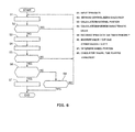
- FIG. 6 is a flow chart illustrating the flow of the wheel position determination control process according to the first embodiment.
- the sensor ID being "1" is assumed.
- the wheel position determination control process is also carried out in parallel.
- step S 1 the rotational position calculation unit 4 a receives the TPMS data with the sensor ID being1.
- step S2 the rotational position detection inhibition unit 4e determines whether or not a brake control is in progress, and, if YES, control returns to step S1, if NO, the control proceeds to step S3.
- step S3 the rotational position calculation section 4 a calculates the rotational position of each wheel 1.
- step S 4 the dispersion calculation unit 4 b calculates the dispersion characteristic values X of the rotational position data of each wheel 1.
- step S 6 a determination is made as to whether the TPMS data with sensor ID being equal to 1 are received for a prescribed number of times (e.g., 10 times) or more. If the determination result is YES, the operation goes to step S 6 . If the determination is NO, the operation returns to step S 1.
- step S 6 the wheel position determination section 4 c determines whether the greatest value of the dispersion characteristics value is over the first threshold of 0.57, and whether the value of the remaining dispersion characteristic values are less than the second threshold of 0.37. If the determination is YES, the operation goes to step S 7; if the determination result is NO, the operation goes to step S8.
- step S 7 the wheel position determination section 4 c determines the wheel position of the rotational position data corresponding to the highest dispersion characteristic value as the wheel position of the sensor ID. Then, the auto-learning mode ends.
- step S 8 the wheel position determination section 4 c determines whether a predetermined cumulative or accumulated running time (e.g., 8 min.) has elapsed from the start of the auto-learning mode. If the determination result is YES, the auto-learning mode is terminated. If the determination result is NO, the operation returns to step S 1 .
- a predetermined cumulative or accumulated running time e.g. 8 min.
- the wheel position determination section 4 c can determine the wheel positions for all of the sensor IDs within the prescribed accumulated travel time, the correspondence relationship between the sensor ID and the wheel position is updated and stored in the memory 4 d for registration. On the other hand, when it has been impossible to determine the wheel position for all of the sensor IDs within the prescribed accumulated travel time, the correspondence relationship between the sensor IDs and each wheel position currently stored in the memory 4 d is continued to be used.
- the TPMS sensor 2 works as follows: when the vehicle stop determination time right before the start of vehicle running is 15 min or longer, a determination is made that there is a possibility that the tire rotation has been carried out, and the operation goes from the normal mode to the constant position transmission mode. In the constant position transmission mode, after 16 seconds has elapsed from the transmission time of the previous time and the rotational position of own TPMS sensor reaches the top point, each TPMS sensor 2 transmits the TPMS data.
- the TPMSCU 4 goes from the monitoring mode to the auto-learning mode.
- the TPMSCU 4 calculates the rotational position (the number of teeth of the rotor) of each wheel 1 when the rotational position of the TPMS sensor 2 reaches the top point based on the input time of the count value of the wheel speed pulses, the time of completion of receipt of the TPMS data, and the like. This is carried out repeatedly for 10 or more times and accumulated as the rotational position data.
- the wheel position to which the rotational position data with least degree of dispersion is determined as the wheel position of that TPMS sensor 2.
- each wheel 1 When the vehicle travels or runs, the rotation speed of each wheel 1 may different from each other due to the difference in tracks between the outer and inner wheels, the lock and the slip of the wheels 1, and the difference in the pneumatic pressure of the tires. Even when the vehicle runs straight, as the driver still may make minute corrections on the steering wheel and there is a certain difference in the road surface between he left and right sides, the difference in the rotation speed still develops between the front and rear wheels 1 FL and 1 FR, and between the left and right wheels 1 RL and 1 RR.
- FIG. 7 illustrates the relationship between the rotational positions (the number of teeth of the rotors) of the wheels 1 FL, 1 FR, 1 RL, and 1 RR when the rotational position of the TPMS sensor 2 FL of the left front wheel 1 FL reaches the top point and the number of times of reception of the TPMS data.
- (a) corresponds to the wheel speed sensor 8 FL of the left front wheel 1 FL
- (b) corresponds to the wheel speed sensor 8 FR of the right front wheel 1 FR
- (c) corresponds to the wheel speed sensor 8 RL of the left rear wheel 1 RL
- (d) corresponds to the wheel speed sensor 8 RR of the right rear wheel 1 RR.
- the dispersion degree of the wheel position obtained from the wheel speed sensor 8 FL with respect to the own wheel is the smallest or least, so that the output period of the TPMS sensor 2 FL and the output period of the wheel speed sensor 8 FL are nearly synchronized with each other.
- an inclination sensor is arranged for each TPMS sensor, and the relationship between the wheel position of the TPMS sensor and the inclination angle is used to determine the wheel position of the TPMS sensor.
- the difference in the rotation velocity takes place between the 4 wheels, so that the correspondence between the wheel position of the TPMS sensor and the inclination angle varies.
- the same number of receivers as those of the TPMS sensors are arranged neighboring the sensors, respectively; based on the electromagnetic wave intensity of the received wireless signals, the wheel position of each TPMS sensor is determined.
- 4 receivers should be arranged. Consequently, the cost is higher.
- the wheel position of each TPMS sensor 2 may be specified without using the electromagnetic wave intensity, so that it is possible to determine the wheel position of each TPMS sensor 2 independent of the reception environment and the layout.
- one receiver 3 is sufficient, which would lead to elimination of the cost for additional sensors.
- the TPMSCU 4 calculates and determines that the rotational position of each wheel 1 is positioned at the top point based on the gravity acceleration dependent component of an acceleration in the centrifugal direction that is detectable from the G sensor 2b. Since the G sensor 2b is used in the existing tire pneumatic pressure monitoring device for detection of vehicle stop and travel, the existing TPMS sensor may be commonly used so that there is no need to add new sensors on the side of the vehicle. The cost can thus be reduced.
- the dispersion degree of the rotational position cannot be determined using the general dispersion formula defined by the average of the "square of the difference from the average or mean.”
- the dispersion calculation unit 4b works as follows.
- the rotational position ⁇ of each wheel 1 obtained from each wheel speed sensor 8 is converted to the circumferential coordinates (cos ⁇ , sin ⁇ ) of a unit circle having the origin (0, 0) at the center.
- the coordinates (cos ⁇ , sin ⁇ ) are taken as vectors, the average vectors (ave_cos ⁇ , ave_sin ⁇ ) of the vectors of the same rotational position data are acquired, and the scalar quantity of the average vector is calculated as the dispersion characteristic value X.
- FIG. 8 shows a diagram illustrating a change in the dispersion characteristic value X in accordance with the number of receipt of the TPMS data.
- the own wheel shows the dispersion characteristic value X calculated on the rotational position data of the wheel speed sensor 8 on the same wheel to which the TPMS sensor is installed, whereas the other wheels show the dispersion characteristic value X calculated on the rotational position data of the wheel speed sensor 8 on the wheel different from those to which the TPMS sensors are installed.
- the wheel position determination unit 4c compares the dispersion characteristic values on each rotational position data with respect to a specific sensor ID at receipt of the TPMS data with respect to that specific sensor ten times or more, and detects that the maximum value of the dispersion characteristic values X exceeds a first threshold value 0.57 while the remaining three dispersion characteristic values fall below a second threshold value 0.37, then the wheel position of the rotational position data corresponding to the maximum dispersion characteristic value X will be identified as the wheel position of that sensor ID.
- the maximum value of the dispersion characteristic values by comparing the maximum value with the first threshold value (0.57), a certain degree of determination accuracy may be ensured.
- a predetermined difference (of 0.2 or more) can be confirmed, which further enhances the determination accuracy. Therefore, at a relatively small number of receipt such as ten times, both the determination accuracy and shortening of determination time may be achieved.
- Each TPMS sensor 2 transmits TPMS data after 16 seconds has elapsed from the previous transmission time of TPMS data and at the timing at which the own rotational position reaches the top point.
- the dispersion characteristic values X of each rotational position data are compared to each other for determination of the wheel position, with respect to the TPMS sensor 2 which has transmitted TPMS data, a certain amount of cumulative travel distance will be necessary in order to cause a difference in the dispersion characteristic values X between own wheel (same wheel) and other wheel (other vehicle wheel).
- the TPMS sensor 2 Upon transmitting TPMS data forty (40) times during the constant position transmission mode, the TPMS sensor 2 transfers to the normal mode.
- the TPMS sensor 2 consumes the power of the button battery 2e at the transmission of the TPMS data so that the battery life time of the button battery 2e will be shorter as the constant position transmission mode continues.
- the constant position transmission mode will be terminated to transfer to the normal mode, which may suppress decrease in battery life time.
- the TPMSCU4 cannot determine the correspondence between each sensor ID and each wheel position despite elapsed time of cumulative travel of eight (8) minutes, the auto-learning mode will be terminated and the process transitions to the monitoring mode.
- the total number of TPMS data is thirty (30) times or less when the cumulative travel time has passed eight minutes, the auto-learning mode may be terminated substantially in synchronization with the completion of the constant position transmission mode of the TPMS sensor 2.
- the sensor CU2c of the TPMS sensor 2 detects the rotational position of the TPMS sensor 2 based on the gravity acceleration dependent component of the centrifugal acceleration detected by the G sensor 2b during the constant position transmission mode and transmits the TPMS data at the peak of the gravity acceleration dependent component so that the TPMS data will be transmitted at the top point at all times of transmission.
- the centrifugal acceleration exerted on the TPMS sensor 2 may be subject to change due to the acceleration/deceleration of the wheel 1, the gravity acceleration dependent component constantly draws a waveform of constant width (-1 to 1 [G]) and changes with a extremely shorter period compared to the speed of change in the centrifugal acceleration accompanied by the vehicle acceleration/deceleration. Therefore, it is easy to grasp the change in the gravity acceleration dependent component based on the centrifugal accelerations.
- the wheel 1 under control is subject to vibrate longitudinally in an extremely short period due to that control, the centrifugal acceleration detected by the G sensor 2b will be affected and fluctuates in an extremely short period with a large width or amplitude (several tens [G] or more).
- the sensor CU2c might falsely determine the shake or fluctuations as the peak in the gravitational acceleration dependent component so that the likelihood exists that the TPMS data will be transmitted at a rotational position other than the peak.
- the rotational position calculation unit 4a of the TPMSCU4 calculates the rotational position of each wheel 1 at the timing at which the rotational position of each TPMS sensor 2 has reached its peak based on the timing of receipt of the TPMS data and the count value of wheel speed pulses for each wheel at that timing. Therefore, the rotational position calculation unit 4a calculates the rotational position of each wheel 1 which has been transmitted at the rotational position other than the top point as that transmitted at the top point and the dispersion calculation unit 4b is to calculate the dispersion characteristic value X for each wheel 1 by including that rotational position in the rotational position data. Consequently, due to inclusion of false rotational position data into the rotational position data for each wheel, the creation of the difference between the maximum value and the other values for each dispersion characteristic value X will be delayed and the wheel position determination will be delayed.
- the rotational position detection inhibition unit 4e inhibits the rotational position calculation unit 4a from detecting the rotational position for each wheel when a brake control such as an ABS control is being executed.
- the rotational position of the wheel may be detected in good accuracy.
- G sensor may detect the acceleration exerted in a rotational direction of the tire and detects the rotational position on that acceleration detected.
- the accelerations acting on the tire is "0" [G] either at a top or bottom of the tire while assumes "1" [G] or "-1” [G] at the front and aft direction, respectively. Therefore, by transmitting TPMS data at the timing when the detection value of the acceleration sensor assumes "1" or "-1", the TPMS data may be transmitted at a constant rotational position.
Landscapes
- Engineering & Computer Science (AREA)
- Mechanical Engineering (AREA)
- Physics & Mathematics (AREA)
- General Physics & Mathematics (AREA)
- Computer Networks & Wireless Communication (AREA)
- Measuring Fluid Pressure (AREA)
- Regulating Braking Force (AREA)
- Arrangements For Transmission Of Measured Signals (AREA)
Applications Claiming Priority (2)
| Application Number | Priority Date | Filing Date | Title |
|---|---|---|---|
| JP2011096674A JP5853402B2 (ja) | 2011-04-25 | 2011-04-25 | タイヤ空気圧モニター装置 |
| PCT/JP2012/053972 WO2012147395A1 (fr) | 2011-04-25 | 2012-02-20 | Dispositif de contrôle de la pression d'air d'un pneu |
Publications (3)
| Publication Number | Publication Date |
|---|---|
| EP2703192A1 true EP2703192A1 (fr) | 2014-03-05 |
| EP2703192A4 EP2703192A4 (fr) | 2015-03-18 |
| EP2703192B1 EP2703192B1 (fr) | 2016-08-24 |
Family
ID=47071923
Family Applications (1)
| Application Number | Title | Priority Date | Filing Date |
|---|---|---|---|
| EP12777592.2A Active EP2703192B1 (fr) | 2011-04-25 | 2012-02-20 | Dispositif de contrôle de la pression d'air d'un pneu |
Country Status (10)
| Country | Link |
|---|---|
| US (1) | US8943882B2 (fr) |
| EP (1) | EP2703192B1 (fr) |
| JP (1) | JP5853402B2 (fr) |
| KR (1) | KR101477949B1 (fr) |
| CN (1) | CN103492199B (fr) |
| BR (1) | BR112013027401B1 (fr) |
| MX (1) | MX2013011757A (fr) |
| MY (1) | MY163967A (fr) |
| RU (1) | RU2550107C1 (fr) |
| WO (1) | WO2012147395A1 (fr) |
Cited By (2)
| Publication number | Priority date | Publication date | Assignee | Title |
|---|---|---|---|---|
| EP3418080A4 (fr) * | 2017-04-27 | 2019-11-27 | Pacific Industrial Co., Ltd. | Unité de réception et de transmission |
| EP3643541A1 (fr) * | 2018-10-25 | 2020-04-29 | Huf Baolong Electronics Bretten GmbH | Système de surveillance de la pression des pneus |
Families Citing this family (18)
| Publication number | Priority date | Publication date | Assignee | Title |
|---|---|---|---|---|
| BR112013026330B1 (pt) * | 2011-04-15 | 2021-12-07 | Nissan Motor Co., Ltd | Dispositivo de monitoramento de pressão de ar de pneumático |
| JP5736948B2 (ja) | 2011-05-13 | 2015-06-17 | 日産自動車株式会社 | タイヤ空気圧モニタシステム |
| JP2015020481A (ja) * | 2013-07-17 | 2015-02-02 | トヨタ自動車株式会社 | 車輪情報取得装置 |
| JP6257992B2 (ja) * | 2013-10-10 | 2018-01-10 | 太平洋工業株式会社 | タイヤ位置判定システム |
| JP2015131546A (ja) * | 2014-01-10 | 2015-07-23 | 株式会社東海理化電機製作所 | タイヤ位置登録システム |
| JP6372226B2 (ja) * | 2014-07-30 | 2018-08-15 | 株式会社デンソー | 車輪位置検出装置およびそれを備えたタイヤ空気圧検出装置 |
| TWI558579B (zh) * | 2014-10-01 | 2016-11-21 | 財團法人工業技術研究院 | 輪胎位置自動辨識方法與輪胎位置自動辨識系統 |
| FR3028058B1 (fr) * | 2014-10-30 | 2016-12-09 | Continental Automotive France | Procede de pilotage d'un processeur d'un boitier electronique monte sur une roue d'un vehicule automobile |
| DE102015216692A1 (de) * | 2015-09-01 | 2017-03-02 | Continental Automotive Gmbh | Elektronische Radeinheit für ein Fahrzeugrad, sowie Verfahren zum Betreiben einer derartigen elektronischen Radeinheit |
| CN107428213B (zh) * | 2015-09-09 | 2020-04-17 | 太平洋工业株式会社 | 车轮位置确定装置 |
| CN106626993A (zh) * | 2016-12-22 | 2017-05-10 | 深圳市车生活科技有限公司 | 一种tpms轮胎检测系统及方法 |
| RU181539U1 (ru) * | 2017-08-01 | 2018-07-18 | Федеральное государственное бюджетное образовательное учреждение высшего образования "Петрозаводский государственный университет" | Устройство сигнализации блокировки колес на движущемся транспортном средстве |
| CN108583170B (zh) * | 2018-05-23 | 2021-01-05 | 浙江吉利汽车研究院有限公司 | 一种轮胎自定位系统及方法 |
| CN108973541A (zh) * | 2018-06-01 | 2018-12-11 | 上海汽车集团股份有限公司 | 利用胎压监测传感器定位整车轮胎位置的方法 |
| CN108944281A (zh) * | 2018-07-25 | 2018-12-07 | 合肥市智信汽车科技有限公司 | 一种车轮内置监控系统 |
| CN108909378A (zh) * | 2018-07-26 | 2018-11-30 | 宁波琻捷电子科技有限公司 | 车辆轮胎定位方法及系统 |
| CN110667317B (zh) * | 2019-11-07 | 2021-06-15 | 中国民航大学 | 基于加速度数据的车轮位置定位方法 |
| WO2023014239A1 (fr) * | 2021-08-04 | 2023-02-09 | Михаил Михайлович ЗАКАТОВ | Unité de mesure passive de paramètres de l'air dans des pneumatiques et de vitesses angulaires de roues |
Family Cites Families (24)
| Publication number | Priority date | Publication date | Assignee | Title |
|---|---|---|---|---|
| JP3286004B2 (ja) * | 1993-03-29 | 2002-05-27 | マツダ株式会社 | タイヤ空気圧警報装置 |
| JPH06286430A (ja) * | 1993-03-30 | 1994-10-11 | Mazda Motor Corp | タイヤ空気圧警報装置 |
| DE4410941A1 (de) | 1993-03-29 | 1994-10-06 | Mazda Motor | Reifenluftdruckwarnvorrichtung |
| JP3119809B2 (ja) | 1996-01-26 | 2000-12-25 | 住友電気工業株式会社 | タイヤ空気圧低下検出方法および装置 |
| DE19734323B4 (de) * | 1997-08-08 | 2004-05-06 | Continental Aktiengesellschaft | Verfahren zur Durchführung der Zuordnung der Radposition zu Reifendruckkontrollvorrichtungen in einem Reifendruckkontrollsystem eines Kraftfahrzeugs |
| EP1214208A1 (fr) * | 1999-08-16 | 2002-06-19 | The Goodyear Tire & Rubber Company | Procede et systeme pour surveiller un etat dynamique d'un element rotatif, notamment d'un pneumatique |
| DE60206667T2 (de) * | 2001-01-29 | 2006-07-20 | The Goodyear Tire & Rubber Co., Akron | Reifenzustands- Überwachungsverfahren |
| JP4114044B2 (ja) * | 2001-07-17 | 2008-07-09 | トヨタ自動車株式会社 | タイヤ作用力検出装置 |
| JP4637582B2 (ja) * | 2002-08-30 | 2011-02-23 | 株式会社ブリヂストン | 車輪状態監視システム |
| FR2847667B1 (fr) * | 2002-11-22 | 2005-01-07 | Siemens Vdo Automotive | Dispositif de detection de la position d'une roue de vehicule |
| DE102004024388B4 (de) * | 2004-05-17 | 2006-07-06 | Siemens Ag | Vorrichtung und Verfahren zum Bestimmen einer Radposition |
| JP2006138803A (ja) * | 2004-11-15 | 2006-06-01 | Toyota Motor Corp | 車輪状態取得装置および車輪状態通信方法 |
| CN101932460B (zh) * | 2007-12-20 | 2013-07-17 | 倍耐力轮胎股份公司 | 用于管理从包括在轮胎中的多个传感器装置的数据发射的方法和系统 |
| JP4462365B2 (ja) * | 2008-03-19 | 2010-05-12 | 株式会社デンソー | タイヤ空気圧検出装置 |
| JP5182030B2 (ja) * | 2008-11-19 | 2013-04-10 | 日産自動車株式会社 | タイヤ空気圧モニター装置およびタイヤ空気圧モニター方法 |
| JP2011058967A (ja) * | 2009-09-10 | 2011-03-24 | Sanyo Electric Co Ltd | 加速度センサ用補正装置 |
| US8332103B2 (en) * | 2009-09-22 | 2012-12-11 | Schrader Electronics Ltd. | Vehicle wheel auto-location using wheel phase angle information |
| CN101973192B (zh) * | 2010-10-03 | 2013-01-30 | 燕山大学 | 汽车转弯行驶中的轮胎气压监测方法 |
| JP5700118B2 (ja) * | 2011-04-25 | 2015-04-15 | 日産自動車株式会社 | タイヤ空気圧送信装置およびタイヤ空気圧モニタシステム |
| JP5736948B2 (ja) * | 2011-05-13 | 2015-06-17 | 日産自動車株式会社 | タイヤ空気圧モニタシステム |
| JP5803733B2 (ja) * | 2012-02-23 | 2015-11-04 | 株式会社デンソー | 車輪位置検出機能を備えたタイヤ空気圧検出装置 |
| JP2014080176A (ja) * | 2012-09-25 | 2014-05-08 | Tokai Rika Co Ltd | タイヤ位置判定システム |
| JP2014128982A (ja) * | 2012-12-27 | 2014-07-10 | Tokai Rika Co Ltd | タイヤ位置判定システム |
| JP2015013637A (ja) * | 2013-06-03 | 2015-01-22 | 株式会社東海理化電機製作所 | タイヤ位置判定システム |
-
2011
- 2011-04-25 JP JP2011096674A patent/JP5853402B2/ja active Active
-
2012
- 2012-02-20 WO PCT/JP2012/053972 patent/WO2012147395A1/fr not_active Ceased
- 2012-02-20 BR BR112013027401-8A patent/BR112013027401B1/pt active IP Right Grant
- 2012-02-20 RU RU2013152161/11A patent/RU2550107C1/ru active
- 2012-02-20 CN CN201280017720.8A patent/CN103492199B/zh active Active
- 2012-02-20 KR KR1020137027780A patent/KR101477949B1/ko active Active
- 2012-02-20 MY MYPI2013003826A patent/MY163967A/en unknown
- 2012-02-20 MX MX2013011757A patent/MX2013011757A/es active IP Right Grant
- 2012-02-20 US US14/113,174 patent/US8943882B2/en active Active
- 2012-02-20 EP EP12777592.2A patent/EP2703192B1/fr active Active
Cited By (2)
| Publication number | Priority date | Publication date | Assignee | Title |
|---|---|---|---|---|
| EP3418080A4 (fr) * | 2017-04-27 | 2019-11-27 | Pacific Industrial Co., Ltd. | Unité de réception et de transmission |
| EP3643541A1 (fr) * | 2018-10-25 | 2020-04-29 | Huf Baolong Electronics Bretten GmbH | Système de surveillance de la pression des pneus |
Also Published As
| Publication number | Publication date |
|---|---|
| WO2012147395A1 (fr) | 2012-11-01 |
| RU2013152161A (ru) | 2015-05-27 |
| JP5853402B2 (ja) | 2016-02-09 |
| KR20130130080A (ko) | 2013-11-29 |
| EP2703192A4 (fr) | 2015-03-18 |
| MY163967A (en) | 2017-11-15 |
| CN103492199B (zh) | 2016-07-06 |
| US8943882B2 (en) | 2015-02-03 |
| BR112013027401A2 (pt) | 2017-01-17 |
| US20140076040A1 (en) | 2014-03-20 |
| EP2703192B1 (fr) | 2016-08-24 |
| JP2012228892A (ja) | 2012-11-22 |
| RU2550107C1 (ru) | 2015-05-10 |
| CN103492199A (zh) | 2014-01-01 |
| MX2013011757A (es) | 2014-02-11 |
| KR101477949B1 (ko) | 2014-12-30 |
| BR112013027401B1 (pt) | 2021-01-19 |
Similar Documents
| Publication | Publication Date | Title |
|---|---|---|
| EP2703192B1 (fr) | Dispositif de contrôle de la pression d'air d'un pneu | |
| EP2703193B1 (fr) | Dispositif de transmission de la pression d'air d'un pneu et système de contrôle de la pression d'air d'un pneu | |
| EP2708384B1 (fr) | Système de contrôle de pression de pneumatique | |
| EP2708383B1 (fr) | Dispositif de contrôle de la pression de pneu | |
| EP2698265B1 (fr) | Dispositif de contrôle de pression d'air de pneu | |
| US9322744B2 (en) | Tire air pressure monitor device | |
| JP5741765B2 (ja) | タイヤ空気圧モニター装置 |
Legal Events
| Date | Code | Title | Description |
|---|---|---|---|
| PUAI | Public reference made under article 153(3) epc to a published international application that has entered the european phase |
Free format text: ORIGINAL CODE: 0009012 |
|
| 17P | Request for examination filed |
Effective date: 20131018 |
|
| AK | Designated contracting states |
Kind code of ref document: A1 Designated state(s): AL AT BE BG CH CY CZ DE DK EE ES FI FR GB GR HR HU IE IS IT LI LT LU LV MC MK MT NL NO PL PT RO RS SE SI SK SM TR |
|
| DAX | Request for extension of the european patent (deleted) | ||
| A4 | Supplementary search report drawn up and despatched |
Effective date: 20150213 |
|
| RIC1 | Information provided on ipc code assigned before grant |
Ipc: G01L 17/00 20060101ALI20150209BHEP Ipc: B60C 23/04 20060101ALI20150209BHEP Ipc: G08C 17/02 20060101ALI20150209BHEP Ipc: B60C 23/02 20060101AFI20150209BHEP |
|
| GRAP | Despatch of communication of intention to grant a patent |
Free format text: ORIGINAL CODE: EPIDOSNIGR1 |
|
| INTG | Intention to grant announced |
Effective date: 20160519 |
|
| GRAS | Grant fee paid |
Free format text: ORIGINAL CODE: EPIDOSNIGR3 |
|
| GRAA | (expected) grant |
Free format text: ORIGINAL CODE: 0009210 |
|
| AK | Designated contracting states |
Kind code of ref document: B1 Designated state(s): AL AT BE BG CH CY CZ DE DK EE ES FI FR GB GR HR HU IE IS IT LI LT LU LV MC MK MT NL NO PL PT RO RS SE SI SK SM TR |
|
| REG | Reference to a national code |
Ref country code: GB Ref legal event code: FG4D |
|
| REG | Reference to a national code |
Ref country code: CH Ref legal event code: EP |
|
| REG | Reference to a national code |
Ref country code: AT Ref legal event code: REF Ref document number: 822700 Country of ref document: AT Kind code of ref document: T Effective date: 20160915 |
|
| REG | Reference to a national code |
Ref country code: IE Ref legal event code: FG4D |
|
| REG | Reference to a national code |
Ref country code: DE Ref legal event code: R096 Ref document number: 602012022254 Country of ref document: DE |
|
| REG | Reference to a national code |
Ref country code: LT Ref legal event code: MG4D |
|
| REG | Reference to a national code |
Ref country code: NL Ref legal event code: MP Effective date: 20160824 |
|
| REG | Reference to a national code |
Ref country code: FR Ref legal event code: PLFP Year of fee payment: 6 |
|
| REG | Reference to a national code |
Ref country code: AT Ref legal event code: MK05 Ref document number: 822700 Country of ref document: AT Kind code of ref document: T Effective date: 20160824 |
|
| PG25 | Lapsed in a contracting state [announced via postgrant information from national office to epo] |
Ref country code: FI Free format text: LAPSE BECAUSE OF FAILURE TO SUBMIT A TRANSLATION OF THE DESCRIPTION OR TO PAY THE FEE WITHIN THE PRESCRIBED TIME-LIMIT Effective date: 20160824 Ref country code: RS Free format text: LAPSE BECAUSE OF FAILURE TO SUBMIT A TRANSLATION OF THE DESCRIPTION OR TO PAY THE FEE WITHIN THE PRESCRIBED TIME-LIMIT Effective date: 20160824 Ref country code: LT Free format text: LAPSE BECAUSE OF FAILURE TO SUBMIT A TRANSLATION OF THE DESCRIPTION OR TO PAY THE FEE WITHIN THE PRESCRIBED TIME-LIMIT Effective date: 20160824 Ref country code: NL Free format text: LAPSE BECAUSE OF FAILURE TO SUBMIT A TRANSLATION OF THE DESCRIPTION OR TO PAY THE FEE WITHIN THE PRESCRIBED TIME-LIMIT Effective date: 20160824 Ref country code: HR Free format text: LAPSE BECAUSE OF FAILURE TO SUBMIT A TRANSLATION OF THE DESCRIPTION OR TO PAY THE FEE WITHIN THE PRESCRIBED TIME-LIMIT Effective date: 20160824 Ref country code: NO Free format text: LAPSE BECAUSE OF FAILURE TO SUBMIT A TRANSLATION OF THE DESCRIPTION OR TO PAY THE FEE WITHIN THE PRESCRIBED TIME-LIMIT Effective date: 20161124 Ref country code: IT Free format text: LAPSE BECAUSE OF FAILURE TO SUBMIT A TRANSLATION OF THE DESCRIPTION OR TO PAY THE FEE WITHIN THE PRESCRIBED TIME-LIMIT Effective date: 20160824 |
|
| PG25 | Lapsed in a contracting state [announced via postgrant information from national office to epo] |
Ref country code: ES Free format text: LAPSE BECAUSE OF FAILURE TO SUBMIT A TRANSLATION OF THE DESCRIPTION OR TO PAY THE FEE WITHIN THE PRESCRIBED TIME-LIMIT Effective date: 20160824 Ref country code: GR Free format text: LAPSE BECAUSE OF FAILURE TO SUBMIT A TRANSLATION OF THE DESCRIPTION OR TO PAY THE FEE WITHIN THE PRESCRIBED TIME-LIMIT Effective date: 20161125 Ref country code: LV Free format text: LAPSE BECAUSE OF FAILURE TO SUBMIT A TRANSLATION OF THE DESCRIPTION OR TO PAY THE FEE WITHIN THE PRESCRIBED TIME-LIMIT Effective date: 20160824 Ref country code: SE Free format text: LAPSE BECAUSE OF FAILURE TO SUBMIT A TRANSLATION OF THE DESCRIPTION OR TO PAY THE FEE WITHIN THE PRESCRIBED TIME-LIMIT Effective date: 20160824 Ref country code: AT Free format text: LAPSE BECAUSE OF FAILURE TO SUBMIT A TRANSLATION OF THE DESCRIPTION OR TO PAY THE FEE WITHIN THE PRESCRIBED TIME-LIMIT Effective date: 20160824 Ref country code: PT Free format text: LAPSE BECAUSE OF FAILURE TO SUBMIT A TRANSLATION OF THE DESCRIPTION OR TO PAY THE FEE WITHIN THE PRESCRIBED TIME-LIMIT Effective date: 20161226 |
|
| PG25 | Lapsed in a contracting state [announced via postgrant information from national office to epo] |
Ref country code: EE Free format text: LAPSE BECAUSE OF FAILURE TO SUBMIT A TRANSLATION OF THE DESCRIPTION OR TO PAY THE FEE WITHIN THE PRESCRIBED TIME-LIMIT Effective date: 20160824 Ref country code: RO Free format text: LAPSE BECAUSE OF FAILURE TO SUBMIT A TRANSLATION OF THE DESCRIPTION OR TO PAY THE FEE WITHIN THE PRESCRIBED TIME-LIMIT Effective date: 20160824 |
|
| REG | Reference to a national code |
Ref country code: DE Ref legal event code: R097 Ref document number: 602012022254 Country of ref document: DE |
|
| PG25 | Lapsed in a contracting state [announced via postgrant information from national office to epo] |
Ref country code: DK Free format text: LAPSE BECAUSE OF FAILURE TO SUBMIT A TRANSLATION OF THE DESCRIPTION OR TO PAY THE FEE WITHIN THE PRESCRIBED TIME-LIMIT Effective date: 20160824 Ref country code: PL Free format text: LAPSE BECAUSE OF FAILURE TO SUBMIT A TRANSLATION OF THE DESCRIPTION OR TO PAY THE FEE WITHIN THE PRESCRIBED TIME-LIMIT Effective date: 20160824 Ref country code: SM Free format text: LAPSE BECAUSE OF FAILURE TO SUBMIT A TRANSLATION OF THE DESCRIPTION OR TO PAY THE FEE WITHIN THE PRESCRIBED TIME-LIMIT Effective date: 20160824 Ref country code: SK Free format text: LAPSE BECAUSE OF FAILURE TO SUBMIT A TRANSLATION OF THE DESCRIPTION OR TO PAY THE FEE WITHIN THE PRESCRIBED TIME-LIMIT Effective date: 20160824 Ref country code: BE Free format text: LAPSE BECAUSE OF FAILURE TO SUBMIT A TRANSLATION OF THE DESCRIPTION OR TO PAY THE FEE WITHIN THE PRESCRIBED TIME-LIMIT Effective date: 20160824 Ref country code: CZ Free format text: LAPSE BECAUSE OF FAILURE TO SUBMIT A TRANSLATION OF THE DESCRIPTION OR TO PAY THE FEE WITHIN THE PRESCRIBED TIME-LIMIT Effective date: 20160824 Ref country code: BG Free format text: LAPSE BECAUSE OF FAILURE TO SUBMIT A TRANSLATION OF THE DESCRIPTION OR TO PAY THE FEE WITHIN THE PRESCRIBED TIME-LIMIT Effective date: 20161124 |
|
| PLBE | No opposition filed within time limit |
Free format text: ORIGINAL CODE: 0009261 |
|
| STAA | Information on the status of an ep patent application or granted ep patent |
Free format text: STATUS: NO OPPOSITION FILED WITHIN TIME LIMIT |
|
| 26N | No opposition filed |
Effective date: 20170526 |
|
| PG25 | Lapsed in a contracting state [announced via postgrant information from national office to epo] |
Ref country code: SI Free format text: LAPSE BECAUSE OF FAILURE TO SUBMIT A TRANSLATION OF THE DESCRIPTION OR TO PAY THE FEE WITHIN THE PRESCRIBED TIME-LIMIT Effective date: 20160824 |
|
| PG25 | Lapsed in a contracting state [announced via postgrant information from national office to epo] |
Ref country code: MC Free format text: LAPSE BECAUSE OF FAILURE TO SUBMIT A TRANSLATION OF THE DESCRIPTION OR TO PAY THE FEE WITHIN THE PRESCRIBED TIME-LIMIT Effective date: 20160824 |
|
| REG | Reference to a national code |
Ref country code: CH Ref legal event code: PL |
|
| PG25 | Lapsed in a contracting state [announced via postgrant information from national office to epo] |
Ref country code: LI Free format text: LAPSE BECAUSE OF NON-PAYMENT OF DUE FEES Effective date: 20170228 Ref country code: CH Free format text: LAPSE BECAUSE OF NON-PAYMENT OF DUE FEES Effective date: 20170228 |
|
| REG | Reference to a national code |
Ref country code: IE Ref legal event code: MM4A |
|
| PG25 | Lapsed in a contracting state [announced via postgrant information from national office to epo] |
Ref country code: LU Free format text: LAPSE BECAUSE OF NON-PAYMENT OF DUE FEES Effective date: 20170220 |
|
| REG | Reference to a national code |
Ref country code: FR Ref legal event code: PLFP Year of fee payment: 7 |
|
| PG25 | Lapsed in a contracting state [announced via postgrant information from national office to epo] |
Ref country code: IE Free format text: LAPSE BECAUSE OF NON-PAYMENT OF DUE FEES Effective date: 20170220 |
|
| PG25 | Lapsed in a contracting state [announced via postgrant information from national office to epo] |
Ref country code: MT Free format text: LAPSE BECAUSE OF NON-PAYMENT OF DUE FEES Effective date: 20170220 |
|
| PG25 | Lapsed in a contracting state [announced via postgrant information from national office to epo] |
Ref country code: AL Free format text: LAPSE BECAUSE OF FAILURE TO SUBMIT A TRANSLATION OF THE DESCRIPTION OR TO PAY THE FEE WITHIN THE PRESCRIBED TIME-LIMIT Effective date: 20160824 |
|
| PG25 | Lapsed in a contracting state [announced via postgrant information from national office to epo] |
Ref country code: HU Free format text: LAPSE BECAUSE OF FAILURE TO SUBMIT A TRANSLATION OF THE DESCRIPTION OR TO PAY THE FEE WITHIN THE PRESCRIBED TIME-LIMIT; INVALID AB INITIO Effective date: 20120220 |
|
| PG25 | Lapsed in a contracting state [announced via postgrant information from national office to epo] |
Ref country code: CY Free format text: LAPSE BECAUSE OF NON-PAYMENT OF DUE FEES Effective date: 20160824 |
|
| PG25 | Lapsed in a contracting state [announced via postgrant information from national office to epo] |
Ref country code: MK Free format text: LAPSE BECAUSE OF FAILURE TO SUBMIT A TRANSLATION OF THE DESCRIPTION OR TO PAY THE FEE WITHIN THE PRESCRIBED TIME-LIMIT Effective date: 20160824 |
|
| PG25 | Lapsed in a contracting state [announced via postgrant information from national office to epo] |
Ref country code: TR Free format text: LAPSE BECAUSE OF FAILURE TO SUBMIT A TRANSLATION OF THE DESCRIPTION OR TO PAY THE FEE WITHIN THE PRESCRIBED TIME-LIMIT Effective date: 20160824 |
|
| PG25 | Lapsed in a contracting state [announced via postgrant information from national office to epo] |
Ref country code: IS Free format text: LAPSE BECAUSE OF FAILURE TO SUBMIT A TRANSLATION OF THE DESCRIPTION OR TO PAY THE FEE WITHIN THE PRESCRIBED TIME-LIMIT Effective date: 20161224 |
|
| PGFP | Annual fee paid to national office [announced via postgrant information from national office to epo] |
Ref country code: GB Payment date: 20260121 Year of fee payment: 15 |
|
| PGFP | Annual fee paid to national office [announced via postgrant information from national office to epo] |
Ref country code: DE Payment date: 20260121 Year of fee payment: 15 |
|
| PGFP | Annual fee paid to national office [announced via postgrant information from national office to epo] |
Ref country code: FR Payment date: 20260121 Year of fee payment: 15 |