EP2703647A1 - Poppetventil für einen Kompressor - Google Patents
Poppetventil für einen Kompressor Download PDFInfo
- Publication number
- EP2703647A1 EP2703647A1 EP12182691.1A EP12182691A EP2703647A1 EP 2703647 A1 EP2703647 A1 EP 2703647A1 EP 12182691 A EP12182691 A EP 12182691A EP 2703647 A1 EP2703647 A1 EP 2703647A1
- Authority
- EP
- European Patent Office
- Prior art keywords
- support element
- passage
- poppet valve
- bore
- valve according
- Prior art date
- Legal status (The legal status is an assumption and is not a legal conclusion. Google has not performed a legal analysis and makes no representation as to the accuracy of the status listed.)
- Granted
Links
Images


Classifications
-
- F—MECHANICAL ENGINEERING; LIGHTING; HEATING; WEAPONS; BLASTING
- F04—POSITIVE - DISPLACEMENT MACHINES FOR LIQUIDS; PUMPS FOR LIQUIDS OR ELASTIC FLUIDS
- F04B—POSITIVE-DISPLACEMENT MACHINES FOR LIQUIDS; PUMPS
- F04B39/00—Component parts, details, or accessories, of pumps or pumping systems specially adapted for elastic fluids, not otherwise provided for in, or of interest apart from, groups F04B25/00 - F04B37/00
- F04B39/10—Adaptations or arrangements of distribution members
- F04B39/1013—Adaptations or arrangements of distribution members the members being of the poppet valve type
-
- F—MECHANICAL ENGINEERING; LIGHTING; HEATING; WEAPONS; BLASTING
- F04—POSITIVE - DISPLACEMENT MACHINES FOR LIQUIDS; PUMPS FOR LIQUIDS OR ELASTIC FLUIDS
- F04B—POSITIVE-DISPLACEMENT MACHINES FOR LIQUIDS; PUMPS
- F04B39/00—Component parts, details, or accessories, of pumps or pumping systems specially adapted for elastic fluids, not otherwise provided for in, or of interest apart from, groups F04B25/00 - F04B37/00
- F04B39/10—Adaptations or arrangements of distribution members
- F04B39/1053—Adaptations or arrangements of distribution members the members being Hoerbigen valves
-
- F—MECHANICAL ENGINEERING; LIGHTING; HEATING; WEAPONS; BLASTING
- F16—ENGINEERING ELEMENTS AND UNITS; GENERAL MEASURES FOR PRODUCING AND MAINTAINING EFFECTIVE FUNCTIONING OF MACHINES OR INSTALLATIONS; THERMAL INSULATION IN GENERAL
- F16K—VALVES; TAPS; COCKS; ACTUATING-FLOATS; DEVICES FOR VENTING OR AERATING
- F16K15/00—Check valves
- F16K15/02—Check valves with guided rigid valve members
- F16K15/025—Check valves with guided rigid valve members the valve being loaded by a spring
- F16K15/026—Check valves with guided rigid valve members the valve being loaded by a spring the valve member being a movable body around which the medium flows when the valve is open
-
- F—MECHANICAL ENGINEERING; LIGHTING; HEATING; WEAPONS; BLASTING
- F16—ENGINEERING ELEMENTS AND UNITS; GENERAL MEASURES FOR PRODUCING AND MAINTAINING EFFECTIVE FUNCTIONING OF MACHINES OR INSTALLATIONS; THERMAL INSULATION IN GENERAL
- F16K—VALVES; TAPS; COCKS; ACTUATING-FLOATS; DEVICES FOR VENTING OR AERATING
- F16K27/00—Construction of housing; Use of materials therefor
- F16K27/02—Construction of housing; Use of materials therefor of lift valves
- F16K27/0209—Check valves or pivoted valves
-
- Y—GENERAL TAGGING OF NEW TECHNOLOGICAL DEVELOPMENTS; GENERAL TAGGING OF CROSS-SECTIONAL TECHNOLOGIES SPANNING OVER SEVERAL SECTIONS OF THE IPC; TECHNICAL SUBJECTS COVERED BY FORMER USPC CROSS-REFERENCE ART COLLECTIONS [XRACs] AND DIGESTS
- Y10—TECHNICAL SUBJECTS COVERED BY FORMER USPC
- Y10T—TECHNICAL SUBJECTS COVERED BY FORMER US CLASSIFICATION
- Y10T137/00—Fluid handling
- Y10T137/7722—Line condition change responsive valves
- Y10T137/7837—Direct response valves [i.e., check valve type]
- Y10T137/7904—Reciprocating valves
- Y10T137/7922—Spring biased
- Y10T137/7929—Spring coaxial with valve
- Y10T137/7932—Valve stem extends through fixed spring abutment
- Y10T137/7933—Yoke or cage-type support for valve stem
Definitions
- the invention relates to a Poppetventil for a compressor, a reciprocating compressor comprising such Poppetventil and a repair kit for a Poppetventil.
- the publication US2010 / 0090149 discloses a poppet valve for a compressor.
- This Poppet valve has a catcher in which a plurality of holes is mounted.
- a closing element is arranged in each of the holes.
- the closing element is mushroom-shaped and has a stem and a head whose diameter is greater than that of the stem.
- the stem is received in the bore of the catcher and includes a cavity in which a spring is received.
- the spring is supported on its end facing the cavity on a bottom element, which is arranged at the bottom of the hole in the catcher.
- the head of the closing element is designed such that it closes a bore in the valve seat plate in the closed state, wherein the valve seat plate with the catcher via a Screw connection is connected.
- the closing element is held in the pressureless state by the spring such that the bore in the valve seat plate is closed.
- the closing element opens when the pressure of the fluid, in particular of the gas which flows into the holes of the valve seat plate in the Poppetventil exerts a force on the head of the closing element, which exceeds the spring force of the spring.
- US2010 / 0090149 It is proposed to vary the thickness of the floor element. As a result, the bias of the spring is changed and, consequently, the pressure, which has an opening of the closing element result. If in the valve bottom elements of different thickness are used for otherwise identically designed closing elements and springs, the Poppet valve can be used to control the fluid flow rate.
- the object of the invention is to design a Poppetventil which has more advantageous operating characteristics.
- a Poppet valve comprising a catcher, a valve seat and a plurality of closing elements
- the catcher has a plurality of bores extending in an axial direction, the bores being open towards the valve seat and being set at a position opposite to the valve seat
- the valve seat has a plurality of through holes, which are arranged with respect to the holes in the axial direction A opposite, such that each of the through holes by each one of the closing elements is closable
- the support element has at least one bearing element passage arranged eccentrically with respect to the bore
- the floor element has at least one floor element passage arranged eccentrically with respect to the bore
- the Poppet valve according to the invention has the advantage that it has a bore arranged eccentrically with respect to the bore through the support element and the bottom element, so that dirt particles which enter the bore or between the bore and the closure element are discharged from the bore via the eccentrically arranged passage can be.
- the eccentrically arranged passage is arranged in the region of the wall of the bore, which has the advantage that the movement of the closing element promotes the dirt particles toward the passage, resulting in an automatic cleaning and an automatic discharge of the impurities out of the hole.
- the disclosed Poppet valve has the considerable disadvantage that the impact element impinging on the support element has the consequence that the contamination is compressed by the impacting closing element on the support element, so that the impurities accumulate on the support element and the support element therefore already after a relatively short service life only restricted within the bore can move.
- Another disadvantage is that the closing elements wear out prematurely.
- the inventive Poppet valve for a compressor comprises a catcher, a valve seat and a plurality of closing elements.
- the valve seat has a plurality of passage openings, wherein each of the passage openings can be closed by a respective one of the closing elements.
- the catcher has a corresponding to the number of closing elements Number of holes, each closing element is at least partially received in the corresponding hole.
- a support element is arranged in each case in the bore and the spring is in each case arranged between the support element and the closing element.
- the bottom element and the support element have an eccentrically arranged passage, so that the two passages form a passage extending through the floor element and the support element with a corresponding mutual position and / or with a corresponding size.
- Eccentric in this context means that the center axis of the passage is different from the longitudinal center axis of the bore, that is, that the center axis of the passage does not coincide with the longitudinal center axis of the bore.
- the center axis can be offset relative to the longitudinal center axis.
- the center axis and the longitudinal center axis extend mutually parallel to one another.
- the passage comprises an eccentrically arranged in the support element passage.
- the passage comprises an eccentrically arranged in the bottom element passage.
- the passage of the support element may comprise at least one of the following forms: a concave curvature, a V-shaped slot-like recess, a U-shaped slot-like recess or a circumferential recess, which is obtainable by a local reduction of the outer diameter of the support element.
- the support element may have an outer contour which at least partially has a distance of at least 2 mm from the inner wall of the bore.
- the bottom element and the support element are configured so adapted to each other that the passage is constantly open continuously.
- the bottom element and the support element are configured so adapted to each other that the passage is either continuously open depending on the mutual position of the support element with respect to the bottom element, or partially or even completely closed.
- the support element is movably mounted in the bore, in particular rotatable and / or displaceable in the direction of the bore. This mobility of the support element in the bore can additionally support the discharge of dirt from the bore. The fact that the passage changes, depending on the mutual position of the support element to the bottom element, the passage is constantly cleaned by a possibly accumulating pollution, so that it is ensured that the passage is not clogged even during long-term operation of Poppetventils.
- the support element has a guide element for the spring.
- This guide member may be formed as a projection extending within the spring. The spring thus engages around the projection and is fixed by the projection in its position.
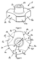
- Fig. 1 shows in a perspective view a Poppetventil 1 in the assembled state.
- the Poppetventil 1 comprises a valve seat 2 and a catcher 3. Between the valve seat 2 and the catcher 3, a Verschleissplatte 6 is arranged.
- the catcher 3 is connected via a bolt 9 with nut 10 to the valve seat 2.
- the valve seat 2 has a plurality of passage openings 12. In the present embodiment, the valve seat 2 comprises eighteen through holes 12 Valve seat 2 can also have a different number of passage openings 12, depending on the diameter and requirement.
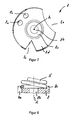
- Fig. 2 shows a longitudinal section through the in FIG. 1 illustrated Poppetventil 1.
- the Verschleissplatte 6 is disposed between the valve seat 2 and the catcher 3.
- the catcher 3 is connected via the bolt 9, the nut 10 and the washer 11 with the valve seat 2.
- the bolt 9 is received in a centrally disposed bore 18 of the catcher 3 with threaded bore 14.
- the bolt 9 has an external thread, which is in engagement with the corresponding threaded bore 14.
- a bolt 17 also prevents mutual rotation of the valve seat 2 and 3 catcher.
- the valve seat 2 has a plurality of passage openings 12. These passage openings 12 can be closed by means of closing elements 4.
- the Verschleissplatte 6 is disposed immediately adjacent to the valve seat 2.
- the Verschleissplatte 6 also contains through holes, which are aligned in the assembled state with the through holes 12 of the valve seat 2.
- the catcher 3 has a plurality of bores 13 extending in an axial direction A, the bores 13 being open towards the valve seat 2 and the borehole 13 terminating in a bottom element 7 at an end opposite the valve seat 2.
- a displaceable in the axial direction A closing elements 4 is arranged, wherein the Valve seat 2 has a plurality of through holes 12, which are arranged opposite to the holes 13 in the axial direction A opposite, such that each of the through holes 12 can be closed by one of the closing elements 4.
- In the bores 13 each have a support element 8 is arranged which rests on the bottom element 7, wherein in each case a spring 5 between the support element 8 and the closing element 4 is arranged to effect a valve seat 2 towards the biasing force on the closing element 4.
- the support element 8 has at least one with respect to the bore 13 and with respect to the axis A eccentrically arranged support element passage 8a.
- the bottom element 7 has at least one with respect to the bore 13 eccentrically arranged Bodenelement screenlass 7a to form in the axial direction A with respect to the bore 13 and the axis A eccentrically arranged passage 16 through the support element 8 and the bottom element 7.
- the closing element 4 is displaceably mounted within the bore 13 in the direction of the axis A.
- the eccentrically arranged passage 16 has the advantage that contaminants, which are located in the gap between the bore 13 and the closing element 4, 4 actively promoted by the lower shoulder or 4b of the closing element through the passage 16 down so that any contamination and impurities are conveyed out of the poppet valve 1 via the passage 16.
- the passage 16 thus has the advantage that the Poppetventil 1 can clean itself automatically, and thereby accumulation and deposition of dirt within the holes 13 considerably reduced or even completely avoided. This results in the advantage that the Poppetventil 1 according to the invention can preferably be operated without maintenance during a longer period of time, for example several 1000 operating hours.
- FIG. 3 shows that in FIG. 2 illustrated support element 8 in a perspective view.
- the support element 8 comprises a base body 8d with a circular outer peripheral surface 8e, wherein the base body 8d in the circumferential direction has at least a portion 8g along which the base body 8d has a reduced diameter to form the support element passage 8a along the portion 8g.
- the reduced diameter is preferably reduced by at least 2 mm.
- the side surface 8h of the support element 8, which forms the eccentrically arranged passage 8a designed concavely running.
- the course of the side surface 8h could be configured to form between the side surface 8h and the inner wall of the bore 13 has a passage 8a.
- the support element 8 in the circumferential direction, a plurality of reduced-diameter side surface 8h to form a plurality of passages 8a in the circumferential direction.
- three passages 8a are formed.
- the base body 8d has a concave course along the section 8g in the circumferential direction.
- the main body 8d as in FIG. 7 illustrated, at least one opening 8a, which forms the support element passage 8a.
- the support element 8 a plurality of circumferentially mutually spaced support element passages 8a.
- the support element 8 has a guide element 8c for the spring 5.
- the support element 8, as in FIG. 2 shown, have a continuous central bore 8b.
- the spring 5 extending in the axial direction A has an outer diameter 5a, wherein the support element passages 8a, as in FIG FIG. 4 represented, outside this outside diameter 5a are arranged.
- FIG. 5 shows a catcher 3 with hole 13 and disposed therein closing element 4 in detail.
- the support element 8 rests on the bottom element 7, wherein the support element 8 and the bottom element 7 are mutually arranged such that a passage 16 is formed via the passages 8a, 7a arranged successively in the direction of progression of the axis A.
- FIG. 6 shows a plan view of the in FIG. 5 shown bottom element 7, wherein the bottom element in the circumferential direction has a plurality of eccentrically arranged passages 7a.
- the bottom element 7 may have a centrally arranged passage 7b.
- both the support element 8 has a central bore 8b and the bottom element 7 has a centrally arranged passage 7b in order to form an additional passage 17 in the center.
- FIG. 5 used support element 8 is as in the FIGS. 3 and 4 designed so that in the in FIG. 5 illustrated arrangement three circumferentially distributed arranged passages 16 form.
- Support element 8 movably arranged in the bore 13 so that it is rotatably and / or slidably mounted in the bore 13 in the axial direction A. This rotation and / or displacement has an additional cleaning effect, and helps to promote any impurities out of the bore 13.
- FIG. 7 shows in a plan view of a support element 8 with three different embodiments of eccentrically arranged passages 8a.
- the right-hand passage 8a corresponds to the in FIG. 4 shown passage 8a and was associated with FIG. 4 already described in detail.
- the passage 8a can also, as in the top left in FIG. 7 represented, designed as an opening or as a bore. It could be distributed distributed in the circumferential direction one or more such openings.
- the passages may be configured in a variety of ways, such that they are arranged eccentrically with respect to the center axis A of the support element 8.
- the FIG. 7 shows below another exemplary passage 8a, which is designed slot-shaped or v-shaped.
- This in FIG. 6 bottom element 7 shown must have at least one eccentrically arranged passage 7a.
- the at least one passage 7a may be configured in a variety of forms, and for example, the in FIG. 7 having illustrated shapes of the passages 8a. It is only important that the eccentrically arranged passages 7a, 8a are arranged mutually adapted so that a common passage 16 can form.
- the support element 8 is rotatably mounted in the bore 13.
- the eccentrically arranged passages 7a, 8a designed so adapted to each other that at least during certain periods of time and preferably continuously an open passage 16 is formed.
- the support member 8 can be configured in a variety of embodiments to fulfill the function of holding the spring 5 in a central position and also having an eccentrically arranged passage 8a.
- FIG. 8 shows a further embodiment of such a support element 8 with a circular guide element 8c, within which the spring 5 rests on the support element 8 and is centered.
- the support element 8 also has at least one eccentrically arranged passage 8a, of which, by way of example, a possible embodiment is shown.
- the support element 8 can also be designed disc-shaped, without a guide element 8c.
- the support element 8 with respect to the wall of the bore 13 a game, so that the support element 8 can perform radially to the bore 13 an oscillatory movement.
- a repair kit for the Poppetventil 1 is also provided, wherein the repair kit comprises at least one closing element 4 and at least one support element 8 with an eccentrically arranged support element passage 8a.
- the closing elements 4 and the support elements 8 are subject to wear during operation of the poppet valve 1, so that after a certain period of operation replace. It may prove advantageous if the repair kit also includes at least one spring 5.
- any existing dirt is advantageously discharged together with a flowing between the wall of the bore 13 and the closing element 4 bypass fluid.
- An accumulation of dirt deposit in the region of the support element 8 and / or the bottom element 7 is avoided, so that advantageously a continuous operation of the poppet valve over a period of, for example, several thousand operating hours is possible.
- bottom elements 7 and / or support elements 8 of the individual embodiments can be combined as desired.
- a bottom element 7 or a support element 8 can also have a plurality of differently shaped eccentrically arranged passages 7a, 8a.
- the poppet valve 1 comprises, as in FIG. 2 It is possible to provide at least some of the bottom elements 7 and / or the support elements 8 with differently shaped eccentrically arranged passages 7a, 8a.
- FIG. 9 shows in the center of a through hole 12 a, undercommun which, as in FIG. 2 represented, a sliding closure element 4, a bottom element 7 with Bodenelement trimlass 7 a and a support element 8 are provided with spring 5, so that the in FIG.
- Poppet valve 1 shown also in the center has a through hole 12a, which is closable via the closing element 4.
- the passage opening 12a and the bore 13 arranged underneath and the closing element 4 displaceably mounted therein with spring 5 are preferably designed identically to those in FIG FIG. 2 represented passage opening 12 with bore 13, closing element 4 and spring 5.
- Poppetventil 1 could be designed such that it has a arranged in the center through hole 12 instead of the screw bolt 9.
- Such an embodiment has opposite to in the Figures 1 and 2 illustrated embodiment has the advantage that it has a larger number of passage openings 12,12a, and thus allows a larger flow rate.
Landscapes
- Engineering & Computer Science (AREA)
- General Engineering & Computer Science (AREA)
- Mechanical Engineering (AREA)
- Check Valves (AREA)
- Compressor (AREA)
- Lift Valve (AREA)
- Details Of Valves (AREA)
Abstract
Description
- Die Erfindung betrifft ein Poppetventil für einen Kompressor, einen Kolbenkompressor umfassend ein derartiges Poppetventil sowie einen Reparatursatz für ein Poppetventil.
- Die Druckschrift
US2010/0090149 offenbart ein Poppetventil für einen Kompressor. Dieses Poppetventil weist einen Fänger auf, in welchem eine Mehrzahl von Bohrungen angebracht ist. In jeder der Bohrungen ist ein Schliesselement angeordnet. Das Schliesselement ist pilzförmig ausgestaltet und weist einen Stiel und einen Kopf auf, dessen Durchmesser grösser als der des Stiels ist. Der Stiel ist in der Bohrung des Fängers aufgenommen und enthält einen Hohlraum, in welchem eine Feder aufgenommen ist. Die Feder stützt sich an seinem dem Hohlraum gegenüber liegenden Ende auf einem Bodenelement ab, welches am Grund der Bohrung im Fänger angeordnet ist. - Der Kopf des Schliesselements ist derart ausgestaltet, dass er im geschlossenen Zustand eine Bohrung in der Ventilsitzplatte verschliesst, wobei die Ventilsitzplatte mit dem Fänger über eine Schraubverbindung verbunden ist. Das Schliesselement wird im drucklosen Zustand durch die Feder derart gehalten, dass die Bohrung in der Ventilsitzplatte geschlossen ist.
- Das Schliesselement öffnet, wenn der Druck des Fluides, insbesondere des Gases, welches in die Bohrungen der Ventilsitzplatte in das Poppetventil einströmt, eine Kraft auf den Kopf des Schliesselements ausübt, welche die Federkraft der Feder übersteigt. Gemäss
US2010/0090149 wird vorgeschlagen, die Dicke des Bodenelements zu variieren. Hierdurch wird die Vorspannung der Feder verändert und demzufolge der Druck, der eine Öffnung des Schliesselements zur Folge hat. Wenn in dem Ventil Bodenelemente verschiedener Dicke für ansonsten gleichartig ausgestaltete Schliesselemente und Federn verwendet werden, kann das Poppetventil zur Regelung des Fluiddurchsatzes verwendet werden. - Das aus der Druckschrift
US2010/0090149 bekannte Poppetventil weist den Nachteil auf, dass dieses nach einer gewissen Betriebsdauer eine beeinträchtigte Funktionsweise aufweist, insbesondere wenn das Ventil mit einem verschmutzten Fluid betrieben wird, beispielsweise einem Gas welches Tröpfchen oder Partikel enthält. Dies führt zu einer Hemmung oder Blockierung der Bewegung der Schliesselemente, was zur Folge hat, dass die Schliesselemente in geschlossener Position verbleiben oder sich nicht mehr vollständig schliessen. - Aufgabe der Erfindung ist es ein Poppetventil auszugestalten, das vorteilhaftere Betriebseigenschaften aufweist.
- Diese Aufgabe wird gelöst mit einem Poppetventil aufweisend die Merkmale von Anspruch 1. Die Unteransprüche 2 bis 13 betreffen weitere, vorteilhafte Ausgestaltungen der Erfindung. Die Aufgabe wird weiter gelöst mit einem Reparatursatz für ein Poppetventil aufweisend die Merkmale von Anspruch 15.
- Die Aufgabe wird insbesondere gelöst mit einem Poppetventil umfassend einen Fänger, einen Ventilsitz sowie eine Mehrzahl von Schliesselementen, wobei der Fänger eine Mehrzahl von in einer axialen Richtung verlaufende Bohrungen aufweist, wobei die Bohrungen zum Ventilsitz hin offen sind und an einem bezüglich dem Ventilsitz entgegen gesetzten Ende ein Bodenelement aufweisen, wobei in den Bohrungen jeweils ein in axialer Richtung A verschiebbares Schliesselement angeordnet ist, wobei der Ventilsitz eine Mehrzahl von Durchgangsöffnungen aufweist, welche bezüglich den Bohrungen in axialer Richtung A gegenüber liegend angeordnet sind, derart, dass jede der Durchgangsöffnungen durch je eines der Schliesselemente verschliessbar ist, wobei in den Bohrungen jeweils ein Auflageelement angeordnet ist und wobei jeweils eine Feder zwischen dem Auflageelement und dem Schliesselement angeordnet ist, um eine zum Ventilsitz hin ausgerichtete Vorspannkraft auf das Schliesselement zu bewirken, wobei das Auflageelement zumindest einen bezüglich der Bohrung exzentrisch angeordneten Auflageelementdurchlass aufweist und wobei das Bodenelement zumindest einen bezüglich der Bohrung exzentrisch angeordneten Bodenelementdurchlass aufweist, um in axialer Richtung A einen bezüglich der Bohrung exzentrisch angeordneten Durchgang durch das Auflageelement sowie das Bodenelement auszubilden.
- Das erfindungsgemässe Poppetventil weist den Vorteil auf, dass dieses einen bezüglich der Bohrung exzentrisch angeordneten Durchgang durch das Auflageelement sowie das Bodenelement aufweist, sodass sich Schmutzpartikel, welche in die Bohrung beziehungsweise zwischen die Bohrung und das Schliesselement gelangen über den exzentrisch angeordneten Durchgang aus der Bohrung ausgetragen werden können. In einer besonders vorteilhaften Ausgestaltung ist der exzentrisch angeordnete Durchgang im Bereich der Wand der Bohrung angeordnet, was den Vorteil ergibt, dass die Bewegung des Schliesselementes die Schmutzpartikel in Richtung zum Durchgang hin fördert, sodass sich eine selbsttätige Reinigung ergibt und ein selbsttätiger Austrag der Verunreinigungen aus der Bohrung hinaus erfolgt. Das in der Druckschrift
US 2010/0090149 offenbarte Poppetventil weist dagegen den erheblichen Nachteil auf, dass das auf das Auflageelement aufprallende Schliesselement zur Folge hat, dass die Verunreinigung durch das aufprallende Schliesselement auf dem Auflageelement komprimiert werden, sodass sich die Verunreinigungen am Auflageelement kumulieren und das Auflageelement sich deshalb bereits nach relativ kurzer Betriebsdauer nur noch eingeschränkt innerhalb der Bohrung bewegen lässt. Ein weiterer Nachteil besteht darin, dass die Schliesselemente vorzeitig verschleissen. - Das erfindungsgemässe Poppetventil für einen Kompressor umfasst einen Fänger, einen Ventilsitz sowie eine Mehrzahl von Schliesselementen. Der Ventilsitz weist eine Mehrzahl von Durchgangsöffnungen auf, wobei jede der Durchgangsöffnungen durch je eines der Schliesselemente verschliessbar ist. Der Fänger weist eine zu der Anzahl der Schliesselemente korrespondierende Anzahl von Bohrungen auf, wobei jedes Schliesselement zumindest teilweise in der korrespondierenden Bohrung aufgenommen ist. Ein Auflageelement ist jeweils in der Bohrung angeordnet und die Feder ist jeweils zwischen dem Auflageelement und dem Schliesselement angeordnet. Das Bodenelement und das Auflageelement weisen einen exzentrisch angeordneten Durchlass auf, sodass die beiden Durchlasse bei entsprechender gegenseitiger Lage und/oder bei entsprechender Grösse einen durch das Bodenelement sowie das Auflageelement verlaufenden Durchgang ausbilden. Exzentrisch bedeutet in diesem Zusammenhang, dass die Mittenachse des Durchlasses verschieden von der Längsmittenachse der Bohrung ist, das heisst, dass die Mittenachse des Durchlasses nicht mit der Längsmittenachse der Bohrung zusammenfällt. Insbesondere kann die Mittenachse versetzt zu der Längsmittenachse verlaufen. In einer besonders vorteilhaften Ausführungsform verlaufen die Mittenachse und die Längsmittenachse gegenseitig parallel zueinander.
- In einer vorteilhaften Ausführungsform umfasst der Durchgang einen exzentrisch im Auflageelement angeordneten Durchlass. Zudem umfasst der Durchgang einen exzentrisch im Bodenelement angeordneten Durchlass. Insbesondere kann der Durchlass des Auflageelements zumindest eine der nachfolgenden Formen umfassen: eine konkave Krümmung, eine v-förmige schlitzartige Ausnehmung, eine u-förmige schlitzartige Ausnehmung oder eine umfangsseitige Ausnehmung, welche durch eine lokale Verringerung des Aussendurchmessers des Auflageelements erhältlich ist. In einer weiteren Ausführungsform kann das Auflageelement eine Aussenkontur aufweisen, die zumindest teilweise einen Abstand von zumindest 2 mm von der Innenwand der Bohrung aufweist.
- In einer besonders vorteilhaften Ausführungsform sind das Bodenelement sowie das Auflageelement derart gegenseitig angepasst ausgestaltet, dass der Durchgang ständig durchgehend geöffnet ist. In einer weiteren, vorteilhaften Ausführungsform sind das Bodenelement sowie das Auflageelement derart gegenseitig angepasst ausgestaltet, dass der Durchgang abhängig von der gegenseitigen Lage vom Auflageelement bezüglich dem Bodenelement entweder durchgehend geöffnet ist, oder teilweise oder sogar vollständig geschlossen ist. In einer vorteilhaften Ausführungsform ist das Auflageelement bewegglich in der Bohrung gelagert, insbesondere drehbar und/oder in Verlaufsrichtung der Bohrung verschiebbar. Diese Beweglichkeit des Auflageelements in der Bohrung kann den Austrag von Verschmutzungen aus der Bohrung zusätzlich unterstützen. Dadurch, dass sich der Durchgang verändert, abhängig von der gegenseitigen Lage vom Auflageelement zum Bodenelement, wird der Durchgang ständig von einer sich allfällig anlagernden Verschmutzung gereinigt, sodass gewährleistet ist, dass der Durchgang auch während eines langfristigen Betriebs des Poppetventils nicht verstopft wird.
- In einer vorteilhaften Ausgestaltung weist das Auflageelement ein Führungselement für die Feder auf. Dieses Führungselement kann als ein Vorsprung ausgebildet sein, der sich innerhalb der Feder erstreckt. Die Feder umgreift somit den Vorsprung und wird durch den Vorsprung in seiner Lage fixiert.
- Die Erfindung wird nachfolgend an Hand von Ausführungsbeispielen im Detail beschrieben.
- Die zur Erläuterung der Ausführungsbeispiele verwendeten Zeichnungen zeigen:
- Fig. 1
- eine Ansicht eines erfindungsgemässen Poppetventils;
- Fig. 2
- einen Längsschnitt durch das Poppetventil gemäss
Fig. 1 ; - Fig. 3
- eine Ansicht eines Auflageelements;
- Fig. 4
- eine Draufsicht auf das Auflageelement gemäss
Fig. 3 ; - Fig. 5
- eine Detailansicht eines Poppetventils;
- Fig. 6
- eine Draufsicht auf ein Bodenelement;
- Fig. 7
- eine Draufsicht auf beispielhafte Ausführungsformen von Auflageelementen;
- Fig. 8
- eine Seitenansicht eines weiteren Ausführungsbeispiels eines Auflageelementes
- Fig. 9
- eine perspektivische Ansicht eines weiteren Ausführungsbeispiels eines Poppetventils.
- Grundsätzlich sind in den Zeichnungen gleiche Teile mit gleichen Bezugszeichen versehen.
-
Fig. 1 zeigt in einer perspektivischen Ansicht ein Poppetventil 1 in zusammengebautem Zustand. Das Poppetventil 1 umfasst einen Ventilsitz 2 sowie einen Fänger 3. Zwischen dem Ventilsitz 2 und dem Fänger 3 ist eine Verschleissplatte 6 angeordnet. Der Fänger 3 ist über einen Schraubenbolzen 9 mit Mutter 10 mit dem Ventilsitz 2 verbunden. Der Ventilsitz 2 weist eine Mehrzahl von Durchgangsöffnungen 12 auf. Im vorliegenden Ausführungsbeispiel umfasst der Ventilsitz 2 achtzehn Durchgangsöffnungen 12. Ein Ventilsitz 2 kann je nach Durchmesser und Erfordernis auch eine andere Anzahl Durchgangsöffnungen 12 aufweisen. -
Fig. 2 zeigt einen Längsschnitt durch das inFigur 1 dargestellte Poppetventil 1. Im dargestellten Ausführungsbeispiel ist zwischen dem Ventilsitz 2 und dem Fänger 3 die Verschleissplatte 6 angeordnet. In einem weiteren, nicht dargestellten Ausführungsbeispiel könnte auf diese Verschleissplatte 6 auch verzichtet werden. Der Fänger 3 ist über den Schraubenbolzen 9, die Mutter 10 sowie die Unterlagscheibe 11 mit dem Ventilsitz 2 verbunden. Der Schraubenbolzen 9 ist in einer zentrisch angeordneten Bohrung 18 des Fängers 3 mit Gewindebohrung 14 aufgenommen. Der Schraubenbolzen 9 weist ein Aussengewinde auf, welches mit der entsprechenden Gewindebohrung 14 im Eingriff steht. Ein Bolzen 17 verhindert zudem eine gegenseitige Verdrehung von Ventilsitz 2 und Fänger 3. - Der Ventilsitz 2 weist eine Mehrzahl von Durchgangsöffnungen 12 auf. Diese Durchgangsöffnungen 12 sind mittels Schliesselementen 4 verschliessbar. Die Verschleissplatte 6 ist unmittelbar angrenzend an den Ventilsitz 2 angeordnet. Die Verschleissplatte 6 enthält ebenfalls Durchgangsöffnungen, die im zusammengebauten Zustand mit den Durchgangsöffnungen 12 des Ventilsitzes 2 fluchten.
- Der Fänger 3 weist eine Mehrzahl von in einer axialen Richtung A verlaufenden Bohrungen 13 auf, wobei die Bohrungen 13 zum Ventilsitz 2 hin offen sind und wobei die Bohrung 13 an einem bezüglich dem Ventilsitz 2 entgegen gesetzten Ende in einem Bodenelement 7 endet. In jeder Bohrung 13 ist jeweils ein in axialer Richtung A verschiebbares Schliesselemente 4 angeordnet, wobei der Ventilsitz 2 eine Mehrzahl von Durchgangsöffnungen 12 aufweist, welche bezüglich den Bohrungen 13 in axialer Richtung A gegenüber liegend angeordnet sind, derart, dass jede der Durchgangsöffnungen 12 durch je eines der Schliesselemente 4 verschliessbar ist. In den Bohrungen 13 ist jeweils ein Auflageelement 8 angeordnet welches am Bodenelement 7 anliegt, wobei jeweils eine Feder 5 zwischen dem Auflageelement 8 und dem Schliesselement 4 angeordnet ist, um eine zum Ventilsitz 2 hin ausgerichtete Vorspannkraft auf das Schliesselement 4 zu bewirken. Das Auflageelement 8 weist zumindest einen bezüglich der Bohrung 13 beziehungsweise einen bezüglich der Achse A exzentrisch angeordneten Auflageelementdurchlass 8a auf. Zudem weist das Bodenelement 7 zumindest einen bezüglich der Bohrung 13 exzentrisch angeordneten Bodenelementdurchlass 7a aufweist, um in axialer Richtung A einen bezüglich der Bohrung 13 beziehungsweise der Achse A exzentrisch angeordneten Durchgang 16 durch das Auflageelement 8 sowie das Bodenelement 7 auszubilden.
- Das Schliesselement 4 ist innerhalb der Bohrung 13 in Verlaufsrichtung der Achse A verschiebbar gelagert. Der exzentrisch angeordnete Durchgang 16 weist den Vorteil auf, dass Verschmutzungen, welche sich im Spalt zwischen der Bohrung 13 und dem Schliesselement 4 befinden, von der unteren Schulter 4b des Schliesselementes 4 durch den Durchgang 16 aktiv nach unten gefördert beziehungsweise gestossen werden, sodass allfällige Verschmutzungen und Verunreinigungen über den Durchgang 16 nach unten aus dem Poppetventil 1 hinausgefördert werden. Der Durchgang 16 weist somit den Vorteil auf, dass das Poppetventil 1 sich selbsttätig reinigen kann, und dass dadurch eine Ansammlung und Ablagerung von Schmutz innerhalb der Bohrungen 13 erheblich reduziert oder sogar gänzlich vermieden wird. Dies ergibt den Vorteil, dass das erfindungsgemässe Poppetventil 1 vorzugsweise während eine längeren Zeitspanne beispielsweise mehreren 1000 Betriebsstunden wartungsfrei betrieben werden kann.
-
Figur 3 zeigt das inFigur 2 dargestellte Auflageelement 8 in perspektivischer Ansicht. Das Auflageelement 8 umfasst einen Grundkörper 8d mit einer kreisförmig verlaufenden Aussenumfangsfläche 8e, wobei der Grundkörper 8d in Umfangsrichtung zumindest ein Abschnitt 8g aufweist, entlang welchem der Grundkörper 8d einen reduzierten Durchmesser aufweist, um entlang des Abschnitts 8g den Auflageelementdurchlass 8a auszubilden. Der reduzierte Durchmesser reduziert sich vorzugsweise um zumindest 2 mm. Im dargestellten Ausführungsbeispiel ist die Seitenfläche 8h des Auflageelementes 8, welche den exzentrisch angeordneten Durchlass 8a ausbildet, konkav verlaufend ausgestaltet. Es gibt eine Vielzahl von Ausführungsmöglichkeiten wie der Verlauf der Seitenfläche 8h ausgestaltet sein könnte, um zwischen der Seitenfläche 8h und der Innenwand der Bohrung 13 einen Durchlass 8a auszubilden. In einer vorteilhaften Ausgestaltung weist das Auflageelement 8, wie inFigur 4 dargestellt, in Umfangsrichtung eine Mehrzahl von Seitenfläche 8h mit reduziertem Durchmesser auf, um in Umfangsrichtung eine Mehrzahl von Durchlässen 8a auszubilden. Im dargestellten Ausführungsbeispiel werden drei Durchlässe 8a ausgebildet. In einer vorteilhaften Ausgestaltung weist der Grundkörper 8d entlang des Abschnitts 8g in Umfangsrichtung einen konkaven Verlauf auf. In einer weiteren vorteilhaften Ausgestaltung weist der Grundkörper 8d, wie inFigur 7 dargestellt, zumindest eine Durchbrechung 8a auf, welche den Auflageelementdurchlass 8a ausbildet. In einer weiteren vorteilhaften Ausgestaltung weist das Auflageelement 8 eine Mehrzahl von in Umfangsrichtung gegenseitig beabstandete Auflageelementdurchlässe 8a auf. In einer vorteilhaften Ausgestaltung weist das Auflageelement 8 ein Führungselement 8c für die Feder 5 auf. Vorteilhafterweise kann das Auflageelement 8, wie inFigur 2 dargestellt, eine durchgehende Zentralbohrung 8b aufweisen. In einer vorteilhaften Ausgestaltung weist die in axialer Richtung A verlaufende Feder 5 einen Aussendurchmesser 5a aufweist, wobei die Auflageelementdurchlässe 8a, wie inFigur 4 dargestellt, ausserhalb dieses Aussendurchmessers 5a angeordnet sind. -
Figur 5 zeigt einen Fänger 3 mit Bohrung 13 und darin angeordnetem Schliesselement 4 im Detail. Das Auflageelement 8 liegt auf dem Bodenelement 7 auf, wobei das Auflageelement 8 und das Bodenelement 7 derart gegenseitig angeordnet sind, dass sich über die in Verlaufsrichtung der Achse A nacheinander folgend angeordneten Durchlässen 8a, 7a ein Durchgang 16 ausbildet.Figur 6 zeigt eine Draufsicht auf das inFigur 5 dargestellte Bodenelement 7, wobei das Bodenelement in Umfangsrichtung eine Mehrzahl von exzentrisch angeordneten Durchlässen 7a aufweist. Zudem kann das Bodenelement 7 einen zentrisch angeordneten Durchlass 7b aufweisen. In einer vorteilhaften Ausgestaltung weist sowohl das Auflageelement 8 eine Zentralbohrung 8b auf als auch das Bodenelement 7 einen zentrisch angeordneten Durchlass 7b auf, um im Zentrum einen zusätzlichen Durchlass 17 auszubilden. Das inFigur 5 verwendete Auflageelement 8 ist wie in denFiguren 3 und 4 dargestellt ausgestaltet, sodass sich in der inFigur 5 dargestellten Anordnung drei in Umfangsrichtung verteilt angeordnete Durchgänge 16 ausbilden. In einer vorteilhaften Ausgestaltung ist das Auflageelement 8 beweglich in der Bohrung 13 angeordnet, sodass dieses drehbar und/oder in axialer Richtung A verschiebbar in der Bohrung 13 gelagert ist. Dieses Drehen und/oder Verschieben weist einen zusätzlichen reinigenden Effekt aus, und hilft allfällige Verunreinigungen aus der Bohrung 13 hinauszufördern. -
Figur 7 zeigt in einer Draufsicht ein Auflageelement 8 mit drei unterschiedlichen Ausführungsformen von exzentrisch angeordneten Durchlässen 8a. Der rechts angeordnete Durchlass 8a entspricht dem inFigur 4 dargestellten Durchlass 8a und wurde im Zusammenhang mitFigur 4 bereits im Detail beschrieben. Der Durchlass 8a kann auch, wie oben links inFigur 7 dargestellt, als Durchbrechung oder als Bohrung ausgestaltet sein. Es könne eine oder auch mehrere derartige Durchbrechungen in Umfangsrichtung verteilt angeordnet sein. Die Durchlässe können in einer Vielzahl von Möglichkeiten ausgestaltet sein, derart, dass diese exzentrisch bezüglich der Mittenachse A des Auflageelementes 8 angeordnet sind. DieFigur 7 zeigt unten einen weiteren beispielhaften Durchlass 8a, der schlitzförmig beziehungsweise v-förmig ausgestaltet ist. - Das in
Figur 6 dargestellte Bodenelement 7 muss zumindest einen exzentrisch angeordneten Durchlass 7a aufweisen. Der zumindest eine Durchlass 7a kann in einer Vielzahl von Formen ausgestaltet sein, und beispielsweise auch die inFigur 7 dargestellten Formen der Durchlässe 8a aufweisen. Wichtig ist einzig, dass die exzentrisch angeordneten Durchlässe 7a, 8a derart gegenseitig angepasst angeordnet sind, dass sich ein gemeinsamer Durchgang 16 ausbilden kann. In einer vorteilhaften Ausgestaltung ist das Auflageelement 8 verdrehbar in der Bohrung 13 gelagert. In einer vorteilhaften Ausgestaltung sind die exzentrisch angeordneten Durchlässe 7a, 8a derart gegenseitig angepasst ausgestaltet, dass sich zumindest während gewissen Zeitabschnitten und vorzugsweise dauernd ein offener Durchgang 16 ausbildet. - Das Auflageelement 8 kann in einer Vielzahl von Ausführungsformen ausgestaltet sein, um die Funktion zu erfüllen die Feder 5 in einer zentralen Lage zu halten und zudem einen exzentrisch angeordneten Durchlass 8a aufzuweisen.
Figur 8 zeigt ein weiteres Ausführungsbeispiel eines derartigen Auflageelementes 8 mit einem kreisförmig verlaufenden Führungselement 8c, innerhalb welchem die Feder 5 auf dem Auflageelement 8 aufliegt und zentriert ist. Das Auflageelement 8 weist zudem zumindest einen exzentrisch angeordneten Durchlass 8a auf, von welchem beispielhaft eine mögliche Ausführungsform dargestellt ist. Das Auflageelement 8 kann jedoch auch scheibenförmig ausgestaltet sein, ohne ein Führungselement 8c. - In einer vorteilhaften Ausgestaltung weist das Auflageelement 8 bezüglich der Wand der Bohrung 13 ein Spiel auf, sodass das Auflageelement 8 radial zur Bohrung 13 eine Oszillationsbewegung ausführen kann.
- In einer vorteilhaften Ausgestaltung ist zudem ein Reparatursatz für das Poppetventil 1 vorgesehen, wobei der Reparatursatz zumindest ein Schliesselement 4 und zumindest ein Auflageelement 8 mit einem exzentrisch angeordneten Auflageelementdurchlass 8a umfasst. Üblicherweise unterliegen die Schliesselemente 4 sowie die Auflageelemente 8 während dem Betrieb des Poppetventils 1 einem Verschleiss, sodass diese nach einer gewissen Betriebszeit zu ersetzen sind. Es kann sich als vorteilhaft erweisen, wenn der Reparatursatz zudem noch zumindest eine Feder 5 umfasst.
- Beim erfindungsgemässen Poppetventil wird allfällig vorhandener Schmutz vorteilhafterweise zusammen mit einem zwischen der Wand der Bohrung 13 und dem Schliesselement 4 fliessenden Bypassfluid ausgetragen. Eine Ansammlung von Schmutzablagerung im Bereich des Auflageelementes 8 und/oder des Bodenelementes 7 wird vermieden, sodass vorteilhafterweise ein kontinuierlicher Betrieb des Poppetventils über einen Zeitraum von beispielsweise mehreren 1000 Betriebsstunden möglich ist.
- Selbstverständlich können die Bodenelemente 7 und/oder Auflageelemente 8 der einzelnen Ausführungsbeispiele beliebig kombiniert werden. Insbesondere kann ein Bodenelement 7 oder ein Auflageelement 8 auch mehrere unterschiedlich ausgeformte exzentrisch angeordnete Durchlässe 7a, 8a aufweisen. Das Poppetventil 1 umfasst, wie in
Figur 2 dargestellt eine Mehrzahl von Bodenelementen 7 und Auflageelementen 8. Es besteht die Möglichkeit zumindest einige der Bodenelemente 7 und/oder der Auflageelemente 8 mit unterschiedlich ausgeformten exzentrisch angeordneten Durchlässen 7a, 8a zu versehen. - In einer weiteren, in
Figur 9 dargestellten Ausführungsform könnte das in denFiguren 1 und 2 dargestellte Poppetventil 1 auch ohne Schraubbolzen 9, Mutter 10, Unterlagscheibe 11 und Gewindebohrung 14 ausgestaltet sein, indem der Ventilsitz 2 und der Fänger 3 über beispielsweise eine Mehrzahl von in Umfangsrichtung verteilt angeordneten Befestigungsmitteln 17 wie Schrauben gegenseitig miteinander verbunden sind. Bei einer solchen Ausgestaltung erweist es sich wie inFigur 9 dargestellt als vorteilhaft im Zentrum ebenfalls ein Schliesselement 4 anzuordnen.Figur 9 zeigt im Zentrum eine Durchgangsöffnung 12a, unterhalbe welcher, wie inFigur 2 dargestellt, ein verschiebbares Schliesselement 4, eine Bodenelement 7 mit Bodenelementdurchlass 7a sowie ein Auflageelement 8 mit Feder 5 vorgesehen sein, sodass das inFigur 9 dargestellte Poppetventil 1 auch im Zentrum eine Durchgangsöffnung 12a aufweist, welche über das Schliesselement 4 verschliessbar ist. Die Durchgangsöffnung 12a und die darunter angeordnete Bohrung 13 und das darin verschiebbar gelagerte Schliesselement 4 mit Feder 5 ist vorzugsweise identisch ausgestaltet wie die inFigur 2 dargestellte Durchgangsöffnung 12 mit Bohrung 13, Schliesselement 4 und Feder 5. Auch das in denFiguren 1 und 2 dargestellte Poppetventil 1 könnte derart ausgestaltet sein, dass dieses an Stelle des Schraubenbolzens 9 eine im Zentrum angeordnete Durchgangsöffnung 12 aufweist. Eine derartige Ausführungsform weist gegenüber der in denFiguren 1 und 2 dargestellten Ausführungsform den Vorteil auf, dass diese eine grössere Anzahl Durchgangsöffnungen 12,12a aufweist, und somit eine grössere Durchflussmenge ermöglicht.
Claims (15)
- Poppetventil (1) für einen Kompressor, umfassend einen Fänger (3), einen Ventilsitz (2) sowie eine Mehrzahl von Schliesselementen (4), wobei der Fänger (3) eine Mehrzahl von in einer axialen Richtung (A) verlaufende Bohrungen (13) aufweist, wobei die Bohrungen (13) zum Ventilsitz (2) hin offen sind und an einem bezüglich dem Ventilsitz (2) entgegen gesetzten Ende ein Bodenelement (7) aufweisen, wobei in den Bohrungen (13) jeweils ein in axialer Richtung (A) verschiebbares Schliesselemente (4) angeordnet ist, wobei der Ventilsitz (2) eine Mehrzahl von Durchgangsöffnungen (12) aufweist, welche bezüglich den Bohrungen (13) in axialer Richtung (A) gegenüber liegend angeordnet sind, derart, dass jede der Durchgangsöffnungen (12) durch je eines der Schliesselemente (4) verschliessbar ist, wobei in den Bohrungen (13) jeweils ein Auflageelement (8) angeordnet ist und wobei jeweils eine Feder (5) zwischen dem Auflageelement (8) und dem Schliesselement (4) angeordnet ist, um eine zum Ventilsitz (2) hin ausgerichtete Vorspannkraft auf das Schliesselement (4) zu bewirken, dadurch gekennzeichnet, dass das Auflageelement (8) zumindest einen bezüglich der Bohrung (13) exzentrisch angeordneten Auflageelementdurchlass (8a) aufweist und dass das Bodenelement (7) zumindest einen bezüglich der Bohrung (13) exzentrisch angeordneten Bodenelementdurchlass (7a) aufweist, um in axialer Richtung (A) einen bezüglich der Bohrung (13) exzentrisch angeordneten Durchgang (16) durch das Auflageelement (8) sowie das Bodenelement (7) auszubilden.
- Poppetventil nach Anspruch 1, dadurch gekennzeichnet, dass der Auflageelementdurchlass (8a) derart ausgestaltet ist, dass das Auflageelement (8) einen Grundkörper (8d) aufweist, welcher am Bodenelement (7) aufliegt, und dass der Grundkörper (8d) in Umfangsrichtung zumindest ein Abschnitt (8g) aufweist, entlang welchem der Grundkörper (8d) einen reduzierten Durchmesser aufweist, um entlang des Abschnitts (8g) den Auflageelementdurchlass (8a) auszubilden, wobei der reduzierte Durchmesser sich vorzugsweise um zumindest 2 mm reduziert.
- Poppetventil nach Anspruch 2, dadurch gekennzeichnet, dass der Grundkörper (8d) entlang des Abschnitts (8g) in Umfangsrichtung einen konkaven Verlauf aufweist.
- Poppetventil nach Anspruch 1, dadurch gekennzeichnet, dass das Auflageelement (8) einen Grundkörper (8d) aufweist, und dass der Grundkörper (8d) zumindest eine Durchbrechung aufweist, welche den Auflageelementdurchlass (8a) ausbildet.
- Poppetventil nach einem der vorhergehenden Ansprüche, dadurch gekennzeichnet, dass in Umfangsrichtung des Auflageelementes (8) eine Mehrzahl von gegenseitig beabstandeten Auflageelementdurchlässen (8a) angeordnet sind.
- Poppetventil nach einem der vorhergehenden Ansprüche, dadurch gekennzeichnet, dass die in axialer Richtung (A) verlaufende Feder (5) einen Aussendurchmesser (5a) aufweist, und dass die Auflageelementdurchlässe (8a) ausserhalb dieses Aussendurchmessers (5a) angeordnet sind.
- Poppetventil nach einem der vorhergehenden Ansprüche, dadurch gekennzeichnet, dass das Bodenelement (7) eine Mehrzahl von in Umfangsrichtung des Bodenelements (7) beabstandet angeordneten Bodenelementdurchlässe (7a) aufweist.
- Poppetventil nach Anspruch 7, dadurch gekennzeichnet, dass die Bodenelementdurchlässe (7a) als Bohrungen ausgestaltet sind.
- Poppetventil nach einem der vorhergehenden Ansprüche, dadurch gekennzeichnet, dass das Auflageelement (8) beweglich in der Bohrung (13) gelagert ist, insbesondere drehbar und/oder in axialer Richtung (A) verschiebbar.
- Poppetventil nach einem der vorhergehenden Ansprüche, dadurch gekennzeichnet, dass der zumindest eine Bodenelementdurchlasse (7a) und der zumindest eine Auflageelementdurchlass (8a) derart gegenseitig angepasst ausgestaltet sind, dass sich in jeder möglichen Lage des Auflageelementes (8) bezüglich dem Bodenelement (7) ein geöffneter Durchgang (16) durch das Auflageelement (8) sowie das Bodenelement (7) ausbildet.
- Poppetventil nach einem der vorhergehenden Ansprüche, dadurch gekennzeichnet, dass das Auflageelement (8) bezüglich der Wand der Bohrung (13) ein Spiel aufweist, derart, dass das Auflageelement (8) radial zur axialen Richtung (A) eine Oszillationsbewegung ausführen kann.
- Poppetventil nach einem der vorhergehenden Ansprüche, dadurch gekennzeichnet, dass das Auflageelement (8) um dessen Längsachse (A) drehbar gelagert ist.
- Poppetventil nach einem der vorhergehenden Ansprüche, wobei das Auflageelement (8) ein Führungselement (8c) für die Feder (5) aufweist.
- Kolbenkompressor umfassend ein Poppetventil (1) nach einem der vorhergehenden Ansprüche.
- Reparatursatz für ein Poppetventil (1) nach einem der vorhergehenden Ansprüche, wobei der Reparatursatz zumindest ein Schliesselement (4) und zumindest ein Auflageelement (8) mit einem exzentrisch angeordneten Auflageelementdurchlass (8a) umfasst.
Priority Applications (5)
| Application Number | Priority Date | Filing Date | Title |
|---|---|---|---|
| EP12182691.1A EP2703647B1 (de) | 2012-08-31 | 2012-08-31 | Poppetventil für einen Kompressor |
| PCT/EP2013/068093 WO2014033296A1 (de) | 2012-08-31 | 2013-09-02 | Poppetventil für einen kompressor |
| CN201380045375.3A CN104603462B (zh) | 2012-08-31 | 2013-09-02 | 用于压缩机的提升阀 |
| JP2015529040A JP6174147B2 (ja) | 2012-08-31 | 2013-09-02 | 圧縮機のポペットバルブ及びポペットバルブを備えるピストン圧縮機 |
| US14/424,364 US9309878B2 (en) | 2012-08-31 | 2013-09-02 | Poppet valve for a compressor |
Applications Claiming Priority (1)
| Application Number | Priority Date | Filing Date | Title |
|---|---|---|---|
| EP12182691.1A EP2703647B1 (de) | 2012-08-31 | 2012-08-31 | Poppetventil für einen Kompressor |
Publications (2)
| Publication Number | Publication Date |
|---|---|
| EP2703647A1 true EP2703647A1 (de) | 2014-03-05 |
| EP2703647B1 EP2703647B1 (de) | 2017-10-04 |
Family
ID=46762938
Family Applications (1)
| Application Number | Title | Priority Date | Filing Date |
|---|---|---|---|
| EP12182691.1A Active EP2703647B1 (de) | 2012-08-31 | 2012-08-31 | Poppetventil für einen Kompressor |
Country Status (5)
| Country | Link |
|---|---|
| US (1) | US9309878B2 (de) |
| EP (1) | EP2703647B1 (de) |
| JP (1) | JP6174147B2 (de) |
| CN (1) | CN104603462B (de) |
| WO (1) | WO2014033296A1 (de) |
Cited By (3)
| Publication number | Priority date | Publication date | Assignee | Title |
|---|---|---|---|---|
| WO2017064155A1 (de) * | 2015-10-12 | 2017-04-20 | Burckhardt Compression Ag | Poppetventil |
| WO2017064150A1 (de) * | 2015-10-12 | 2017-04-20 | Burckhardt Compression Ag | Poppetventil |
| EP3330540A1 (de) * | 2016-12-05 | 2018-06-06 | Burckhardt Compression AG | Poppetventil |
Families Citing this family (16)
| Publication number | Priority date | Publication date | Assignee | Title |
|---|---|---|---|---|
| DE112014005029T5 (de) * | 2013-12-03 | 2016-08-11 | Borgwarner Inc. | Rückschlagventil vom Scheibentyp mit hohem Durchfluss und schneller Ansprache für Hydraulikspanner |
| DE202014105513U1 (de) | 2014-11-17 | 2015-01-13 | Burckhardt Compression Ag | Poppetventil für einen Kompressor |
| USD824426S1 (en) * | 2015-10-26 | 2018-07-31 | Delaware Capital Formation, Inc. | Reciprocating gas compressor valve |
| USD816122S1 (en) * | 2015-10-26 | 2018-04-24 | Delaware Capital Formation, Inc. | Sealing element for reciprocating gas compressor valve |
| US10941763B2 (en) | 2015-10-26 | 2021-03-09 | Delaware Capital Formation, Inc. | Reciprocating gas compressor valve |
| USD813912S1 (en) * | 2015-10-26 | 2018-03-27 | Delaware Capital Formation, Inc. | Reciprocating gas compressor valve |
| USD841055S1 (en) * | 2015-10-26 | 2019-02-19 | Delaware Capital Formation, Inc. | Reciprocating gas compressor valve |
| KR102351429B1 (ko) * | 2016-06-21 | 2022-01-14 | 보르그워너 인코퍼레이티드 | 스위치 밸브 조립체 및 그를 포함한 유압 제어 모듈 |
| USD816719S1 (en) * | 2016-10-25 | 2018-05-01 | Delaware Capital Formation, Inc. | Sealing element for reciprocating gas compressor valve |
| CN109139831A (zh) | 2017-06-15 | 2019-01-04 | 博格华纳公司 | 带有刚度可控止回阀的张紧器 |
| KR20200115642A (ko) | 2018-02-26 | 2020-10-07 | 보르그워너 인코퍼레이티드 | 내부 리저버 기술 일차 보어를 갖는 가변력 텐셔너 |
| EP3762638B1 (de) * | 2018-03-08 | 2022-03-02 | Burckhardt Compression AG | Plattenventil sowie verfahren zum betrieb desselben |
| JP2020101279A (ja) | 2018-12-21 | 2020-07-02 | ボーグワーナー インコーポレーテッド | 内部チェックバルブを含むピストンが備えられたテンショナ |
| US11781664B2 (en) * | 2020-04-23 | 2023-10-10 | Aci Services, Inc. | Valve poppets and valve seats for high-speed reciprocating compressor capacity unloaders |
| US12181046B2 (en) | 2021-04-13 | 2024-12-31 | Borgwarner Inc. | Variable stiffness function through a check valve in a hydraulic |
| US11391279B1 (en) * | 2021-04-14 | 2022-07-19 | Dresser-Rand Company | Compressor valve assembly with removably affixed guide in a reciprocating compressor |
Citations (3)
| Publication number | Priority date | Publication date | Assignee | Title |
|---|---|---|---|---|
| US4607660A (en) * | 1985-05-13 | 1986-08-26 | Ingersoll-Rand Company | Uni-directional-flow, fluid valve assembly |
| US5511583A (en) * | 1995-01-24 | 1996-04-30 | Dover Resources, Inc. | Compressor valve |
| US20100090149A1 (en) | 2008-10-01 | 2010-04-15 | Compressor Engineering Corp. | Poppet valve assembly, system, and apparatus for use in high speed compressor applications |
Family Cites Families (4)
| Publication number | Priority date | Publication date | Assignee | Title |
|---|---|---|---|---|
| US2125137A (en) * | 1936-11-27 | 1938-07-26 | Nordberg Manufacturing Co | Valve |
| EP1247982B1 (de) * | 2001-04-04 | 2005-02-23 | Hoerbiger Kompressortechnik Holding GmbH | Ringplattenventil für Kolbenkompressoren |
| JP4587778B2 (ja) * | 2004-11-01 | 2010-11-24 | カルソニックカンセイ株式会社 | 吐出側構造及びこれに用いる逆止弁、並びにこれらを用いた圧縮機 |
| JP2010139031A (ja) * | 2008-12-15 | 2010-06-24 | Tgk Co Ltd | 逆止弁 |
-
2012
- 2012-08-31 EP EP12182691.1A patent/EP2703647B1/de active Active
-
2013
- 2013-09-02 JP JP2015529040A patent/JP6174147B2/ja active Active
- 2013-09-02 CN CN201380045375.3A patent/CN104603462B/zh active Active
- 2013-09-02 WO PCT/EP2013/068093 patent/WO2014033296A1/de not_active Ceased
- 2013-09-02 US US14/424,364 patent/US9309878B2/en active Active
Patent Citations (3)
| Publication number | Priority date | Publication date | Assignee | Title |
|---|---|---|---|---|
| US4607660A (en) * | 1985-05-13 | 1986-08-26 | Ingersoll-Rand Company | Uni-directional-flow, fluid valve assembly |
| US5511583A (en) * | 1995-01-24 | 1996-04-30 | Dover Resources, Inc. | Compressor valve |
| US20100090149A1 (en) | 2008-10-01 | 2010-04-15 | Compressor Engineering Corp. | Poppet valve assembly, system, and apparatus for use in high speed compressor applications |
Cited By (7)
| Publication number | Priority date | Publication date | Assignee | Title |
|---|---|---|---|---|
| WO2017064155A1 (de) * | 2015-10-12 | 2017-04-20 | Burckhardt Compression Ag | Poppetventil |
| WO2017064150A1 (de) * | 2015-10-12 | 2017-04-20 | Burckhardt Compression Ag | Poppetventil |
| WO2017064154A1 (de) * | 2015-10-12 | 2017-04-20 | Burckhardt Compression Ag | Poppetventil |
| US10436203B2 (en) | 2015-10-12 | 2019-10-08 | Burckhardt Compression Ag | Poppet valve |
| US10859078B2 (en) | 2015-10-12 | 2020-12-08 | Burckhardt Compression Ag | Poppet valve |
| EP3330540A1 (de) * | 2016-12-05 | 2018-06-06 | Burckhardt Compression AG | Poppetventil |
| WO2018104122A1 (de) * | 2016-12-05 | 2018-06-14 | Burckhardt Compression Ag | Poppetventil |
Also Published As
| Publication number | Publication date |
|---|---|
| CN104603462B (zh) | 2017-07-04 |
| JP6174147B2 (ja) | 2017-08-02 |
| JP2015526649A (ja) | 2015-09-10 |
| WO2014033296A1 (de) | 2014-03-06 |
| EP2703647B1 (de) | 2017-10-04 |
| US9309878B2 (en) | 2016-04-12 |
| US20150204319A1 (en) | 2015-07-23 |
| CN104603462A (zh) | 2015-05-06 |
Similar Documents
| Publication | Publication Date | Title |
|---|---|---|
| EP2703647B1 (de) | Poppetventil für einen Kompressor | |
| DE2305668C2 (de) | Kegelventil | |
| EP3221621B1 (de) | Ventiloberteil | |
| EP1154831B1 (de) | Flüssigkeitsfilter mit demontierbarem, zentralen bauteil, mit zusätzlichem haltebauteil | |
| DE2635166C3 (de) | Saug- und Druckventil für Kolbenverdichter | |
| DE102004044158B3 (de) | Wasserauslaufmundstück mit einem umschaltbaren Strahlreglereinsatz | |
| DE202004001674U1 (de) | Doppelplattenschieber | |
| EP0715692B1 (de) | Pumpenschutzventil | |
| DE3004970A1 (de) | Selbstreinigendes ventil | |
| EP3362713B1 (de) | Poppetventil | |
| DE102007022826A1 (de) | Bauteil für einen Ventiltrieb einer Brennkraftmaschine | |
| DE102014200150A1 (de) | Ventileinrichtung zum Steuern eines Fluids, insbesondere eines abrasiven Dickstoffs | |
| DE60309280T2 (de) | Integriertes Ringventil für einen Kompressorkolben | |
| EP1957176B1 (de) | Wechselölfilter mit federbetätigtem dorn für ablauf | |
| EP0887559B1 (de) | Mehrwegeventil | |
| DE1813237A1 (de) | Sperrschieber fuer abrasive Materialien | |
| DE3917155A1 (de) | Pneumatische schlagmaschine | |
| EP1245881B1 (de) | Vielsitziges Poppetventil | |
| DE202014105513U1 (de) | Poppetventil für einen Kompressor | |
| DE20119207U1 (de) | Pneumatische Brems- und Dämpfeinrichtung für bewegbare Möbelteile | |
| DE10324801A1 (de) | Gießpfannenschieber | |
| DE102004048683B4 (de) | Ventil | |
| DE10028398B4 (de) | Rückschlagventil | |
| DE102004020754B4 (de) | Ventildrehvorrichtung für Auslassventile, insbesondere Schiffsdieselmotoren | |
| DE102018213712A1 (de) | Ventilanordnung |
Legal Events
| Date | Code | Title | Description |
|---|---|---|---|
| AK | Designated contracting states |
Kind code of ref document: A1 Designated state(s): AL AT BE BG CH CY CZ DE DK EE ES FI FR GB GR HR HU IE IS IT LI LT LU LV MC MK MT NL NO PL PT RO RS SE SI SK SM TR |
|
| AX | Request for extension of the european patent |
Extension state: BA ME |
|
| PUAI | Public reference made under article 153(3) epc to a published international application that has entered the european phase |
Free format text: ORIGINAL CODE: 0009012 |
|
| 17P | Request for examination filed |
Effective date: 20140904 |
|
| RBV | Designated contracting states (corrected) |
Designated state(s): AL AT BE BG CH CY CZ DE DK EE ES FI FR GB GR HR HU IE IS IT LI LT LU LV MC MK MT NL NO PL PT RO RS SE SI SK SM TR |
|
| GRAP | Despatch of communication of intention to grant a patent |
Free format text: ORIGINAL CODE: EPIDOSNIGR1 |
|
| RAP1 | Party data changed (applicant data changed or rights of an application transferred) |
Owner name: BURCKHARDT COMPRESSION AG |
|
| INTG | Intention to grant announced |
Effective date: 20170322 |
|
| GRAS | Grant fee paid |
Free format text: ORIGINAL CODE: EPIDOSNIGR3 |
|
| GRAA | (expected) grant |
Free format text: ORIGINAL CODE: 0009210 |
|
| AK | Designated contracting states |
Kind code of ref document: B1 Designated state(s): AL AT BE BG CH CY CZ DE DK EE ES FI FR GB GR HR HU IE IS IT LI LT LU LV MC MK MT NL NO PL PT RO RS SE SI SK SM TR |
|
| REG | Reference to a national code |
Ref country code: GB Ref legal event code: FG4D Free format text: NOT ENGLISH |
|
| REG | Reference to a national code |
Ref country code: CH Ref legal event code: EP |
|
| REG | Reference to a national code |
Ref country code: AT Ref legal event code: REF Ref document number: 934313 Country of ref document: AT Kind code of ref document: T Effective date: 20171015 |
|
| REG | Reference to a national code |
Ref country code: CH Ref legal event code: NV Representative=s name: DR. GRAF AND PARTNER AG INTELLECTUAL PROPERTY, CH |
|
| REG | Reference to a national code |
Ref country code: IE Ref legal event code: FG4D Free format text: LANGUAGE OF EP DOCUMENT: GERMAN |
|
| REG | Reference to a national code |
Ref country code: DE Ref legal event code: R096 Ref document number: 502012011373 Country of ref document: DE |
|
| REG | Reference to a national code |
Ref country code: NL Ref legal event code: MP Effective date: 20171004 |
|
| REG | Reference to a national code |
Ref country code: LT Ref legal event code: MG4D |
|
| PG25 | Lapsed in a contracting state [announced via postgrant information from national office to epo] |
Ref country code: NL Free format text: LAPSE BECAUSE OF FAILURE TO SUBMIT A TRANSLATION OF THE DESCRIPTION OR TO PAY THE FEE WITHIN THE PRESCRIBED TIME-LIMIT Effective date: 20171004 |
|
| PG25 | Lapsed in a contracting state [announced via postgrant information from national office to epo] |
Ref country code: LT Free format text: LAPSE BECAUSE OF FAILURE TO SUBMIT A TRANSLATION OF THE DESCRIPTION OR TO PAY THE FEE WITHIN THE PRESCRIBED TIME-LIMIT Effective date: 20171004 Ref country code: FI Free format text: LAPSE BECAUSE OF FAILURE TO SUBMIT A TRANSLATION OF THE DESCRIPTION OR TO PAY THE FEE WITHIN THE PRESCRIBED TIME-LIMIT Effective date: 20171004 Ref country code: SE Free format text: LAPSE BECAUSE OF FAILURE TO SUBMIT A TRANSLATION OF THE DESCRIPTION OR TO PAY THE FEE WITHIN THE PRESCRIBED TIME-LIMIT Effective date: 20171004 Ref country code: ES Free format text: LAPSE BECAUSE OF FAILURE TO SUBMIT A TRANSLATION OF THE DESCRIPTION OR TO PAY THE FEE WITHIN THE PRESCRIBED TIME-LIMIT Effective date: 20171004 Ref country code: NO Free format text: LAPSE BECAUSE OF FAILURE TO SUBMIT A TRANSLATION OF THE DESCRIPTION OR TO PAY THE FEE WITHIN THE PRESCRIBED TIME-LIMIT Effective date: 20180104 |
|
| PG25 | Lapsed in a contracting state [announced via postgrant information from national office to epo] |
Ref country code: LV Free format text: LAPSE BECAUSE OF FAILURE TO SUBMIT A TRANSLATION OF THE DESCRIPTION OR TO PAY THE FEE WITHIN THE PRESCRIBED TIME-LIMIT Effective date: 20171004 Ref country code: IS Free format text: LAPSE BECAUSE OF FAILURE TO SUBMIT A TRANSLATION OF THE DESCRIPTION OR TO PAY THE FEE WITHIN THE PRESCRIBED TIME-LIMIT Effective date: 20180204 Ref country code: HR Free format text: LAPSE BECAUSE OF FAILURE TO SUBMIT A TRANSLATION OF THE DESCRIPTION OR TO PAY THE FEE WITHIN THE PRESCRIBED TIME-LIMIT Effective date: 20171004 Ref country code: RS Free format text: LAPSE BECAUSE OF FAILURE TO SUBMIT A TRANSLATION OF THE DESCRIPTION OR TO PAY THE FEE WITHIN THE PRESCRIBED TIME-LIMIT Effective date: 20171004 Ref country code: GR Free format text: LAPSE BECAUSE OF FAILURE TO SUBMIT A TRANSLATION OF THE DESCRIPTION OR TO PAY THE FEE WITHIN THE PRESCRIBED TIME-LIMIT Effective date: 20180105 Ref country code: BG Free format text: LAPSE BECAUSE OF FAILURE TO SUBMIT A TRANSLATION OF THE DESCRIPTION OR TO PAY THE FEE WITHIN THE PRESCRIBED TIME-LIMIT Effective date: 20180104 |
|
| REG | Reference to a national code |
Ref country code: DE Ref legal event code: R097 Ref document number: 502012011373 Country of ref document: DE |
|
| PG25 | Lapsed in a contracting state [announced via postgrant information from national office to epo] |
Ref country code: DK Free format text: LAPSE BECAUSE OF FAILURE TO SUBMIT A TRANSLATION OF THE DESCRIPTION OR TO PAY THE FEE WITHIN THE PRESCRIBED TIME-LIMIT Effective date: 20171004 Ref country code: SK Free format text: LAPSE BECAUSE OF FAILURE TO SUBMIT A TRANSLATION OF THE DESCRIPTION OR TO PAY THE FEE WITHIN THE PRESCRIBED TIME-LIMIT Effective date: 20171004 Ref country code: EE Free format text: LAPSE BECAUSE OF FAILURE TO SUBMIT A TRANSLATION OF THE DESCRIPTION OR TO PAY THE FEE WITHIN THE PRESCRIBED TIME-LIMIT Effective date: 20171004 Ref country code: CZ Free format text: LAPSE BECAUSE OF FAILURE TO SUBMIT A TRANSLATION OF THE DESCRIPTION OR TO PAY THE FEE WITHIN THE PRESCRIBED TIME-LIMIT Effective date: 20171004 |
|
| PLBE | No opposition filed within time limit |
Free format text: ORIGINAL CODE: 0009261 |
|
| STAA | Information on the status of an ep patent application or granted ep patent |
Free format text: STATUS: NO OPPOSITION FILED WITHIN TIME LIMIT |
|
| REG | Reference to a national code |
Ref country code: FR Ref legal event code: PLFP Year of fee payment: 7 |
|
| PG25 | Lapsed in a contracting state [announced via postgrant information from national office to epo] |
Ref country code: SM Free format text: LAPSE BECAUSE OF FAILURE TO SUBMIT A TRANSLATION OF THE DESCRIPTION OR TO PAY THE FEE WITHIN THE PRESCRIBED TIME-LIMIT Effective date: 20171004 Ref country code: PL Free format text: LAPSE BECAUSE OF FAILURE TO SUBMIT A TRANSLATION OF THE DESCRIPTION OR TO PAY THE FEE WITHIN THE PRESCRIBED TIME-LIMIT Effective date: 20171004 Ref country code: RO Free format text: LAPSE BECAUSE OF FAILURE TO SUBMIT A TRANSLATION OF THE DESCRIPTION OR TO PAY THE FEE WITHIN THE PRESCRIBED TIME-LIMIT Effective date: 20171004 |
|
| 26N | No opposition filed |
Effective date: 20180705 |
|
| PG25 | Lapsed in a contracting state [announced via postgrant information from national office to epo] |
Ref country code: MT Free format text: LAPSE BECAUSE OF FAILURE TO SUBMIT A TRANSLATION OF THE DESCRIPTION OR TO PAY THE FEE WITHIN THE PRESCRIBED TIME-LIMIT Effective date: 20171004 |
|
| PG25 | Lapsed in a contracting state [announced via postgrant information from national office to epo] |
Ref country code: SI Free format text: LAPSE BECAUSE OF FAILURE TO SUBMIT A TRANSLATION OF THE DESCRIPTION OR TO PAY THE FEE WITHIN THE PRESCRIBED TIME-LIMIT Effective date: 20171004 |
|
| PG25 | Lapsed in a contracting state [announced via postgrant information from national office to epo] |
Ref country code: MC Free format text: LAPSE BECAUSE OF FAILURE TO SUBMIT A TRANSLATION OF THE DESCRIPTION OR TO PAY THE FEE WITHIN THE PRESCRIBED TIME-LIMIT Effective date: 20171004 |
|
| PG25 | Lapsed in a contracting state [announced via postgrant information from national office to epo] |
Ref country code: LU Free format text: LAPSE BECAUSE OF NON-PAYMENT OF DUE FEES Effective date: 20180831 |
|
| REG | Reference to a national code |
Ref country code: BE Ref legal event code: MM Effective date: 20180831 |
|
| PG25 | Lapsed in a contracting state [announced via postgrant information from national office to epo] |
Ref country code: BE Free format text: LAPSE BECAUSE OF NON-PAYMENT OF DUE FEES Effective date: 20180831 |
|
| REG | Reference to a national code |
Ref country code: CH Ref legal event code: PCOW Free format text: NEW ADDRESS: FRANZ-BURCKHARDT-STRASSE 5, 8404 WINTERTHUR (CH) |
|
| PG25 | Lapsed in a contracting state [announced via postgrant information from national office to epo] |
Ref country code: TR Free format text: LAPSE BECAUSE OF FAILURE TO SUBMIT A TRANSLATION OF THE DESCRIPTION OR TO PAY THE FEE WITHIN THE PRESCRIBED TIME-LIMIT Effective date: 20171004 |
|
| PG25 | Lapsed in a contracting state [announced via postgrant information from national office to epo] |
Ref country code: PT Free format text: LAPSE BECAUSE OF FAILURE TO SUBMIT A TRANSLATION OF THE DESCRIPTION OR TO PAY THE FEE WITHIN THE PRESCRIBED TIME-LIMIT Effective date: 20171004 Ref country code: HU Free format text: LAPSE BECAUSE OF FAILURE TO SUBMIT A TRANSLATION OF THE DESCRIPTION OR TO PAY THE FEE WITHIN THE PRESCRIBED TIME-LIMIT; INVALID AB INITIO Effective date: 20120831 |
|
| PG25 | Lapsed in a contracting state [announced via postgrant information from national office to epo] |
Ref country code: MK Free format text: LAPSE BECAUSE OF NON-PAYMENT OF DUE FEES Effective date: 20171004 Ref country code: IE Free format text: LAPSE BECAUSE OF NON-PAYMENT OF DUE FEES Effective date: 20180831 Ref country code: CY Free format text: LAPSE BECAUSE OF FAILURE TO SUBMIT A TRANSLATION OF THE DESCRIPTION OR TO PAY THE FEE WITHIN THE PRESCRIBED TIME-LIMIT Effective date: 20171004 |
|
| PG25 | Lapsed in a contracting state [announced via postgrant information from national office to epo] |
Ref country code: AL Free format text: LAPSE BECAUSE OF FAILURE TO SUBMIT A TRANSLATION OF THE DESCRIPTION OR TO PAY THE FEE WITHIN THE PRESCRIBED TIME-LIMIT Effective date: 20171004 |
|
| PGFP | Annual fee paid to national office [announced via postgrant information from national office to epo] |
Ref country code: DE Payment date: 20250716 Year of fee payment: 14 |
|
| PGFP | Annual fee paid to national office [announced via postgrant information from national office to epo] |
Ref country code: IT Payment date: 20250728 Year of fee payment: 14 |
|
| PGFP | Annual fee paid to national office [announced via postgrant information from national office to epo] |
Ref country code: GB Payment date: 20250717 Year of fee payment: 14 |
|
| PGFP | Annual fee paid to national office [announced via postgrant information from national office to epo] |
Ref country code: FR Payment date: 20250721 Year of fee payment: 14 Ref country code: AT Payment date: 20250725 Year of fee payment: 14 |
|
| PGFP | Annual fee paid to national office [announced via postgrant information from national office to epo] |
Ref country code: CH Payment date: 20250901 Year of fee payment: 14 |
|
| REG | Reference to a national code |
Ref country code: CH Ref legal event code: R17 Free format text: ST27 STATUS EVENT CODE: U-0-0-R10-R17 (AS PROVIDED BY THE NATIONAL OFFICE) Effective date: 20260408 |