EP2703703A1 - Dichte Durchführungsvorrichtung durch eine Wand für Rohrleitungen - Google Patents
Dichte Durchführungsvorrichtung durch eine Wand für Rohrleitungen Download PDFInfo
- Publication number
- EP2703703A1 EP2703703A1 EP20120306054 EP12306054A EP2703703A1 EP 2703703 A1 EP2703703 A1 EP 2703703A1 EP 20120306054 EP20120306054 EP 20120306054 EP 12306054 A EP12306054 A EP 12306054A EP 2703703 A1 EP2703703 A1 EP 2703703A1
- Authority
- EP
- European Patent Office
- Prior art keywords
- annular
- support
- seal
- annular seal
- passage device
- Prior art date
- Legal status (The legal status is an assumption and is not a legal conclusion. Google has not performed a legal analysis and makes no representation as to the accuracy of the status listed.)
- Granted
Links
Images


Classifications
-
- F—MECHANICAL ENGINEERING; LIGHTING; HEATING; WEAPONS; BLASTING
- F16—ENGINEERING ELEMENTS AND UNITS; GENERAL MEASURES FOR PRODUCING AND MAINTAINING EFFECTIVE FUNCTIONING OF MACHINES OR INSTALLATIONS; THERMAL INSULATION IN GENERAL
- F16L—PIPES; JOINTS OR FITTINGS FOR PIPES; SUPPORTS FOR PIPES, CABLES OR PROTECTIVE TUBING; MEANS FOR THERMAL INSULATION IN GENERAL
- F16L5/00—Devices for use where pipes, cables or protective tubing pass through walls or partitions
- F16L5/02—Sealing
- F16L5/08—Sealing by means of axial screws compressing a ring or sleeve
-
- F—MECHANICAL ENGINEERING; LIGHTING; HEATING; WEAPONS; BLASTING
- F16—ENGINEERING ELEMENTS AND UNITS; GENERAL MEASURES FOR PRODUCING AND MAINTAINING EFFECTIVE FUNCTIONING OF MACHINES OR INSTALLATIONS; THERMAL INSULATION IN GENERAL
- F16L—PIPES; JOINTS OR FITTINGS FOR PIPES; SUPPORTS FOR PIPES, CABLES OR PROTECTIVE TUBING; MEANS FOR THERMAL INSULATION IN GENERAL
- F16L5/00—Devices for use where pipes, cables or protective tubing pass through walls or partitions
- F16L5/02—Sealing
- F16L5/025—Sealing the pipe being movable
-
- H—ELECTRICITY
- H02—GENERATION; CONVERSION OR DISTRIBUTION OF ELECTRIC POWER
- H02G—INSTALLATION OF ELECTRIC CABLES OR LINES, OR OF COMBINED OPTICAL AND ELECTRIC CABLES OR LINES
- H02G3/00—Installations of electric cables or lines or protective tubing therefor in or on buildings, equivalent structures or vehicles
- H02G3/22—Installations of cables or lines through walls, floors or ceilings, e.g. into buildings
Definitions
- the invention relates to the sealed passage of a pipe through a partition, and more particularly to the sealed passage of a pipe allowing to maintain a freedom of movement of a pipe in all directions.
- this hole is usually filled after the insertion of the pipe, so as to plug the orifice, and make the passage tight.
- the tightness of the passage also allows for sound insulation.
- the passage of a duct through a partition is likely to pose a number of problems when the conduit and the partition are moved, for example by expansion, independently of one another. especially when the movements are not in phase.
- the tightness of the passage can then be compromised.
- the conduit may be damaged.
- the risk of leaks is important.
- the ducts pass through the exterior walls of a building through a concrete basement wall.
- the passages in these walls are made after the installation of the piping, without sealing, and the conduits are fixed from lateral attachments preventing any lateral displacement.
- the conduits are fixed from lateral attachments preventing any lateral displacement.
- the lateral fasteners generate additional loads on the conduit structure, and the addition of expansion joints, entails additional costs.
- the invention therefore relates to a sealed passage device for piping, comprising a fixing ring intended to be fixed on a conduit, a support intended to be fixed on a partition around a duct passage orifice, and a deformable annular sealing gasket disposed between the fixing ring and the support.
- the annular shape of the seal makes it possible to marry the contours of the duct.
- the fixing ring intended to be fixed on the duct cooperates with the annular seal to create a seal around the duct.
- the tightness of the passage is finalized by maintaining the seal on the support in a sealed manner.
- the elasticity of the seal allows the conduit to move relative to the partition in the three directions of space, while maintaining the seal of the seal always ensuring contact surfaces between the joints, and therefore the passage.
- the passage device comprises a retaining ring capable of holding the annular seal against the support.
- the retaining ring allows for example to fix the annular seal on the support, for example by tightening the seal between the retaining ring and the support.
- the support is provided with a set of angles, for example four in number, which allow its support and easy maintenance on the partition (not shown).
- the retaining ring may comprise two semicircular portions assembling to form a ring.
- the retaining ring By making the retaining ring from two semicircular portions, it is possible to fix the retaining ring on the support while the pipe line is already in place and connected to the rest of the pipe system.
- the attachment ring may be configured to clamp the annular seal on the conduit. For this it is fixed after the annular seal.
- the annular seal may advantageously comprise a first partially annular portion assembled with a second partially annular portion, the first partially annular portion and the second partially annular portion being shaped to overlap at least partially between the fixing ring. and the support and form a sealed annular seal.
- annular seal from two partially annular portions, that is to say forming a ring portion, allows to apply the two portions and form an annular seal while the conduit is already in place in the orifice and connected to the rest of the piping system.
- the at least partial overlap of the two annular portions makes it possible to maintain the tightness of the seal, and consequently of the passage, when the duct is moved or turned relative to the partition in the three directions of space.
- the first and second annular portions overlap at an angle of at least 60 ° in two overlapping areas.
- the fixing ring may comprise an annular shoulder on which the annular seal is supported.
- the seal between the annular seal and the duct is made using the fixing ring sealingly attached to the duct. This provides a tight junction between the shoulder and the deformable annular seal.
- the annular seal may advantageously comprise two annular seals each comprising two semicircular half-seals, the two annular seals being disposed on either side of the annular shoulder of the fixing ring so that that the junction between the two semi-circular half-joints of an annular seal is orthogonal to the junction between the two semicircular half-joints of the other joint.
- the two half-seals are mounted so that the junction between the two hemispherical portions a half-joint is orthogonal to the junction between the two hemispherical portions of the other plate.
- the two half-joints do not overlap, the junction between the two half-joints may not be sealed, especially in the case where the conduit is moved relative to the partition.
- the fixing support, the retaining ring and the annular seal may comprise complementary centering means.
- the complementary centering means thus make it possible to position the two annular half-seals so as to have the two orthogonal junctions.
- the annular seal may advantageously be made of elastic material of rubber or flexible and elastic metal type, especially at high temperature.
- a watertight partition comprising an orifice intended to be traversed by a pipe, comprising a device for leaktight piping as defined above fixed on at least one of the sides of the partition, around of the orifice.
- FIG. 1 On the figure 1 is illustrated a perspective view of a sealed pipe passage according to a first embodiment of the invention.
- figure 2 presents an exploded view of the sealed pipe passage of the figure 1 .
- the sealed passage 1 is made by means of a device comprising a support 2 comprising a hole and intended to be fixed on a partition around a passage opening for a conduit C.
- the support 2 comprises two parts 2a and 2b intended to be juxtaposed so as to form the support 2 around the conduit C.
- the support 2 comprises, on the perimeter of the hole, a receiving zone 3 of an annular seal 4 and a holding ring 5.
- the support 2 also includes angles (not shown) for maintaining the support for attachment to the partition.
- the reception zone 3 comprises bores 6 adapted to receive holding screws.
- the annular seal 4 is made of flexible and elastic material such as rubber or a soft and elastic metal. It comprises two portions 4a and 4b partially annular, that is to say in the form of truncated ring. Each partially annular portion 4a and 4b comprises a generally semicylindrical proximal portion 41 intended to cooperate with the conduit C, a distal portion 42 intended to cooperate with the retaining ring 5 and the support 2, and an intermediate portion 43 located between the proximal portion 41 and the distal portion 42.
- each partially annular portion 4a and 4b form a semicircle, or half a ring.
- the proximal portion 41 of a partially annular portion 4a may cooperate contiguously with the proximal portion 41 of the complementary partial annular portion 4b when the two partially annular portions 4a and 4b are assembled.
- each partially annular portion 4a and 4b each define more than half of a ring, and more particularly two-thirds of a ring, ie 240 °.
- their intermediate portion 43 is partially superimposed on a sector of at least about 60 ° between the support 2 and the fixing ring 7, on the surface separating the pipe C from the circular edge of the support 2.
- the covering between the two intermediate parts 43 thus makes it possible to maintain the tightness of the sealed passage device 1 even when the conduit C is caused to move relative to the support 2.
- the retaining ring 5 also comprises two semicircular parts 5a and 5b intended to be juxtaposed so as to form the retaining ring 5 serving to hold the annular seal 4, and more particularly the distal portions 42 of the partially annular portions 4a. and 4b, against the zone 3 for receiving the support 2.
- the junction between the parts 5a and 5b of the retaining ring 5 is positioned so as not to be located opposite the junction between the distal portions 42 of the partially annular portions 4a and 4b.
- the portions 5a and 5b of the holding ring 5 are angularly displaced by a quarter turn, ie 90 °, relative to the distal portions 42 of the partially annular portions 4a and 4b so as to improve the sealing of the device 1.
- the distal portions 42 of the annular seal 4 comprise orifices 8 and the retaining ring 5 comprises orifices 9.
- the orifices 8 and 9 of the annular seal 4 and of the retaining ring 5 are intended to be positioned facing the bores. 6 of the zone 3 receiving the support 2 for mounting the sealing device 1 with screws holding the annular seal 4 clamped between the support and the retaining ring 5.
- the annular seal 4 is fixed on the conduit C with the aid of a fixing ring 7 which may for example be a clamping collar.
- the fixing ring 7 bears on the proximal portions 41 of the partially annular portions 4a and 4b so as to clamp the proximal portions of the annular seal 4 against the duct C and thus ensure tightness at the level of the duct C.
- the juxtaposition , and therefore the non-overlap of the proximal portions 41 of the partially annular portions 4a and 4b allows the fixing ring 7 to ensure a good seal when clamped on the conduit C.
- the sealed passage device 1 allows, thanks in particular to the overlap of the intermediate portions 42 of the partially annular portions 4a and 4b, to seal even when the conduit C moves relative to the support 2.
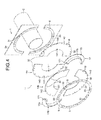
- the fixing ring 17 is shaped so as to comprise a radial shoulder 170.
- the fixing ring 17 comprises two parts 17a and 17b intended to be assembled directly on the conduit C so as to form a ring having a shoulder 170 against which the annular seal 14 can abut to ensure sealing of the sealing device 1 between the conduit C and the annular seal 14.
- the annular seal 14 comprises two flat seals 14a and 14b mounted on either side of the shoulder 170 of the fixing ring 17.
- the two flat seals 14a and 14b are made of deformable material such as rubber or an elastic metal and flexible. They ensure the tightness of the passage even when the conduit C is moved relative to the support 2.
- Each portion 17a and 17b of the fastening ring 17 comprises assembly tabs 171 whose dimensions are smaller than the shoulder 170. Due to their dimensions relative to those of the shoulder, the assembly tabs 171 allow to assemble the fixing ring 17 around the duct C without hindering the annular plates 14a and 14b bearing on the shoulder 170.
- Each annular seal 14a and 14b is made from two identical semicircular half-joints 140 assembled by juxtaposition.
- Each semi-circular half-seal 140 comprises a proximal portion 141 and a distal portion 142 with respect to the duct C.
- the proximal portion 141 of each semicircular half-seal 140 bears against the shoulder 170 of the annular ring. fixing 17.
- the seal is here obtained by the support of the seals 14a and 14b against the shoulder 170 of the fixing ring.
- each semicircular half-seal 140 comprises orifices 18 for fixing the annular seal 14 to the support 2.
- the two annular seals 14a and 14b are mounted so that the junction between the semicircular half-seals 140 of an annular seal 14a is disposed orthogonally at the junction between the semicircular half-seals 140 of the other annular seal 14b, while having the orifices 8 of an annular seal 14a facing the orifices 8 of the opposite annular seal 14b. In this way, the risk of leakage is reduced.
- the junction between the parts 5a and 5b of the retaining ring 5 is positioned orthogonally at the junction between the two semicircular half-seals 140 of the annular seal 14b directly in contact with the retaining ring 5, while maintaining the orifices 9 of the retaining ring aligned with the orifices 18 of the annular seals 14a and 14b.
- the support 2 also comprises centering studs 31 intended to cooperate with centering orifices 32 made on the distal portions 142 of the annular seals 14a and 14b, and with centering orifices 33 made in the holding ring 5.
Landscapes
- Engineering & Computer Science (AREA)
- General Engineering & Computer Science (AREA)
- Mechanical Engineering (AREA)
- Architecture (AREA)
- Civil Engineering (AREA)
- Structural Engineering (AREA)
- Gasket Seals (AREA)
Priority Applications (1)
| Application Number | Priority Date | Filing Date | Title |
|---|---|---|---|
| EP12306054.3A EP2703703B1 (de) | 2012-09-04 | 2012-09-04 | Dichte Durchführungsvorrichtung durch eine Wand für Rohrleitungen |
Applications Claiming Priority (1)
| Application Number | Priority Date | Filing Date | Title |
|---|---|---|---|
| EP12306054.3A EP2703703B1 (de) | 2012-09-04 | 2012-09-04 | Dichte Durchführungsvorrichtung durch eine Wand für Rohrleitungen |
Publications (2)
| Publication Number | Publication Date |
|---|---|
| EP2703703A1 true EP2703703A1 (de) | 2014-03-05 |
| EP2703703B1 EP2703703B1 (de) | 2015-08-19 |
Family
ID=46924378
Family Applications (1)
| Application Number | Title | Priority Date | Filing Date |
|---|---|---|---|
| EP12306054.3A Active EP2703703B1 (de) | 2012-09-04 | 2012-09-04 | Dichte Durchführungsvorrichtung durch eine Wand für Rohrleitungen |
Country Status (1)
| Country | Link |
|---|---|
| EP (1) | EP2703703B1 (de) |
Cited By (11)
| Publication number | Priority date | Publication date | Assignee | Title |
|---|---|---|---|---|
| US9404606B2 (en) | 2013-05-07 | 2016-08-02 | Gabe Coscarella | Backplate for a utility box |
| EP3150891A1 (de) * | 2015-09-29 | 2017-04-05 | HILTI Aktiengesellschaft | Leitungsdurchführung zum durchführen von leitungen durch ein bauteil |
| CN108050306A (zh) * | 2017-11-27 | 2018-05-18 | 马鞍山市海华金属制品有限公司 | 一种多自由度运动的密封装置 |
| US10018287B2 (en) * | 2014-02-28 | 2018-07-10 | Gabe Coscarella | Weather barrier for a building penetration |
| CN110030436A (zh) * | 2019-03-21 | 2019-07-19 | 中国科学院微电子研究所 | 一种穿板密封装置 |
| US10773817B1 (en) | 2018-03-08 | 2020-09-15 | Northrop Grumman Systems Corporation | Bi-directional flow ram air system for an aircraft |
| US10787804B2 (en) | 2017-07-17 | 2020-09-29 | Gabe Coscarella | Weather barrier for a building penetration with a removable collar |
| CN115698572A (zh) * | 2020-06-02 | 2023-02-03 | 烙克赛克有限公司 | 分体板和套筒的组合以及套筒 |
| US20230144012A1 (en) * | 2021-11-05 | 2023-05-11 | Rectorseal, Llc | Line Set Cover |
| US12081005B2 (en) | 2018-12-07 | 2024-09-03 | Gabe Coscarella | Weatherproof enclosure for junction box |
| US12291862B2 (en) | 2020-07-17 | 2025-05-06 | Gabe Coscarella | Support for sealing around a building penetration |
Families Citing this family (1)
| Publication number | Priority date | Publication date | Assignee | Title |
|---|---|---|---|---|
| US10167989B2 (en) | 2016-03-08 | 2019-01-01 | Northrop Grumman Systems Corporation | Multidirectionally deflectable mounting apparatus and method |
Citations (3)
| Publication number | Priority date | Publication date | Assignee | Title |
|---|---|---|---|---|
| US5810400A (en) * | 1996-07-11 | 1998-09-22 | Advanced Polymer Technology, Inc. | Flexible entry boot |
| US5988698A (en) * | 1997-07-08 | 1999-11-23 | Sergio M. Bravo | Flexible penetration fitting |
| EP2228577A1 (de) * | 2009-03-10 | 2010-09-15 | DOYMA GmbH & Co | Dichtungsvorrichtung zum Abdichten eines Durchbruchs |
-
2012
- 2012-09-04 EP EP12306054.3A patent/EP2703703B1/de active Active
Patent Citations (3)
| Publication number | Priority date | Publication date | Assignee | Title |
|---|---|---|---|---|
| US5810400A (en) * | 1996-07-11 | 1998-09-22 | Advanced Polymer Technology, Inc. | Flexible entry boot |
| US5988698A (en) * | 1997-07-08 | 1999-11-23 | Sergio M. Bravo | Flexible penetration fitting |
| EP2228577A1 (de) * | 2009-03-10 | 2010-09-15 | DOYMA GmbH & Co | Dichtungsvorrichtung zum Abdichten eines Durchbruchs |
Cited By (16)
| Publication number | Priority date | Publication date | Assignee | Title |
|---|---|---|---|---|
| US9404606B2 (en) | 2013-05-07 | 2016-08-02 | Gabe Coscarella | Backplate for a utility box |
| US10018287B2 (en) * | 2014-02-28 | 2018-07-10 | Gabe Coscarella | Weather barrier for a building penetration |
| EP3150891A1 (de) * | 2015-09-29 | 2017-04-05 | HILTI Aktiengesellschaft | Leitungsdurchführung zum durchführen von leitungen durch ein bauteil |
| WO2017055237A1 (de) * | 2015-09-29 | 2017-04-06 | Hilti Aktiengesellschaft | Leitungsdurchführung zum durchführen von leitungen durch ein bauteil |
| US10566778B2 (en) | 2015-09-29 | 2020-02-18 | Hilti Aktiengesellschaft | Line feedthrough for feeding lines through a component |
| US10787804B2 (en) | 2017-07-17 | 2020-09-29 | Gabe Coscarella | Weather barrier for a building penetration with a removable collar |
| CN108050306A (zh) * | 2017-11-27 | 2018-05-18 | 马鞍山市海华金属制品有限公司 | 一种多自由度运动的密封装置 |
| CN108050306B (zh) * | 2017-11-27 | 2019-11-19 | 合肥海诺恒信息科技有限公司 | 一种多自由度运动的密封装置 |
| US10773817B1 (en) | 2018-03-08 | 2020-09-15 | Northrop Grumman Systems Corporation | Bi-directional flow ram air system for an aircraft |
| US12081005B2 (en) | 2018-12-07 | 2024-09-03 | Gabe Coscarella | Weatherproof enclosure for junction box |
| CN110030436A (zh) * | 2019-03-21 | 2019-07-19 | 中国科学院微电子研究所 | 一种穿板密封装置 |
| CN115698572A (zh) * | 2020-06-02 | 2023-02-03 | 烙克赛克有限公司 | 分体板和套筒的组合以及套筒 |
| US12291862B2 (en) | 2020-07-17 | 2025-05-06 | Gabe Coscarella | Support for sealing around a building penetration |
| US20230144012A1 (en) * | 2021-11-05 | 2023-05-11 | Rectorseal, Llc | Line Set Cover |
| US12129647B2 (en) * | 2021-11-05 | 2024-10-29 | Rectorseal, Llc | Line set cover |
| US20250052056A1 (en) * | 2021-11-05 | 2025-02-13 | Rectorseal, Llc | Line Set Cover |
Also Published As
| Publication number | Publication date |
|---|---|
| EP2703703B1 (de) | 2015-08-19 |
Similar Documents
| Publication | Publication Date | Title |
|---|---|---|
| EP2703703B1 (de) | Dichte Durchführungsvorrichtung durch eine Wand für Rohrleitungen | |
| EP4071316B1 (de) | Drainagevorrichtung mit einer befestigungsmuffe für ein bauwerk, insbesondere ein gebäudedach oder eine terrasse | |
| FR2588924A1 (fr) | Joint interieur souple d'etancheite pour compresseur | |
| FR2578924A1 (fr) | Moyen de liaison de conduite etanche avec bague d'etancheite comportant une surface plane et une surface de segment de sphere | |
| FR3030682A1 (fr) | Ensemble de canalisation pourvu d'un systeme de drainage. | |
| CA3220249A1 (fr) | Circuit de fluide et procede de raccordement de canalisations d'un tel circuit de fluide | |
| FR2485685A1 (fr) | Joint etanche aux gaz pour le passage d'un conduit a travers une structure | |
| FR3005214A1 (fr) | Boite d'appareillage electrique | |
| FR2599109A1 (fr) | Diaphragme a aimant | |
| US10683957B2 (en) | Pipe connecting joint | |
| FR2820490A1 (fr) | Raccord de tuyau lateral | |
| BE1008705A3 (fr) | Raccord de fixation pour un tube annele. | |
| EP2236899B1 (de) | Vorrichtung zum Schließen des umlaufenden äußeren Rands einer Wandöffnung zur Durchführung einer Leitung | |
| FR2528530A1 (fr) | Distributeur modulaire pour reseau double de canalisations de fluides | |
| EP1925868A1 (de) | Wasserdichte Verbindungseinrichtung | |
| FR2647525A1 (fr) | Garniture d'etancheite entre joints d'elements a assembler pour la pose et le maintien de cables conducteurs electriques | |
| EP1936764B1 (de) | Vorrichtung zur Verbindung von zwei Schienensystemen | |
| US20090148239A1 (en) | Resilient protection of through-foundation pipes | |
| FR3064716A1 (fr) | Systeme d'etancheite a fiabilite amelioree d'un ensemble fluidique | |
| EP1781980A1 (de) | Mechanisch fixierbare abzweigverbindung für quadratische abzweigungsöffnungen | |
| FR3040831B1 (fr) | Boite d'appareillage electrique | |
| FR2554538A1 (fr) | Joint d'etancheite pour branchement d'un element tubulaire sur un tuyau de plus grand diametre | |
| EP2237385B1 (de) | Kabeldurchführungsgarnitur | |
| FR2956131A1 (fr) | Dispositif d'aide au raccordement d'un appareil de gestion d'un fluide, tel qu'un compteur d'eau, sur un circuit ou une canalisation. | |
| FR2658583A1 (fr) | Dispositif de raccordement et d'etancheite pour deux tuyaux montes bout a bout. |
Legal Events
| Date | Code | Title | Description |
|---|---|---|---|
| AK | Designated contracting states |
Kind code of ref document: A1 Designated state(s): AL AT BE BG CH CY CZ DE DK EE ES FI FR GB GR HR HU IE IS IT LI LT LU LV MC MK MT NL NO PL PT RO RS SE SI SK SM TR |
|
| AX | Request for extension of the european patent |
Extension state: BA ME |
|
| PUAI | Public reference made under article 153(3) epc to a published international application that has entered the european phase |
Free format text: ORIGINAL CODE: 0009012 |
|
| 17P | Request for examination filed |
Effective date: 20140708 |
|
| GRAP | Despatch of communication of intention to grant a patent |
Free format text: ORIGINAL CODE: EPIDOSNIGR1 |
|
| RIC1 | Information provided on ipc code assigned before grant |
Ipc: F16L 5/08 20060101ALI20150226BHEP Ipc: F16L 5/02 20060101AFI20150226BHEP |
|
| INTG | Intention to grant announced |
Effective date: 20150320 |
|
| GRAS | Grant fee paid |
Free format text: ORIGINAL CODE: EPIDOSNIGR3 |
|
| GRAA | (expected) grant |
Free format text: ORIGINAL CODE: 0009210 |
|
| AK | Designated contracting states |
Kind code of ref document: B1 Designated state(s): AL AT BE BG CH CY CZ DE DK EE ES FI FR GB GR HR HU IE IS IT LI LT LU LV MC MK MT NL NO PL PT RO RS SE SI SK SM TR |
|
| REG | Reference to a national code |
Ref country code: GB Ref legal event code: FG4D Free format text: NOT ENGLISH |
|
| REG | Reference to a national code |
Ref country code: CH Ref legal event code: EP |
|
| REG | Reference to a national code |
Ref country code: IE Ref legal event code: FG4D Free format text: LANGUAGE OF EP DOCUMENT: FRENCH |
|
| REG | Reference to a national code |
Ref country code: AT Ref legal event code: REF Ref document number: 744063 Country of ref document: AT Kind code of ref document: T Effective date: 20150915 |
|
| REG | Reference to a national code |
Ref country code: DE Ref legal event code: R096 Ref document number: 602012009738 Country of ref document: DE |
|
| REG | Reference to a national code |
Ref country code: AT Ref legal event code: MK05 Ref document number: 744063 Country of ref document: AT Kind code of ref document: T Effective date: 20150819 |
|
| REG | Reference to a national code |
Ref country code: FR Ref legal event code: PLFP Year of fee payment: 4 |
|
| REG | Reference to a national code |
Ref country code: LT Ref legal event code: MG4D |
|
| REG | Reference to a national code |
Ref country code: NL Ref legal event code: MP Effective date: 20150819 |
|
| PG25 | Lapsed in a contracting state [announced via postgrant information from national office to epo] |
Ref country code: FI Free format text: LAPSE BECAUSE OF FAILURE TO SUBMIT A TRANSLATION OF THE DESCRIPTION OR TO PAY THE FEE WITHIN THE PRESCRIBED TIME-LIMIT Effective date: 20150819 Ref country code: GR Free format text: LAPSE BECAUSE OF FAILURE TO SUBMIT A TRANSLATION OF THE DESCRIPTION OR TO PAY THE FEE WITHIN THE PRESCRIBED TIME-LIMIT Effective date: 20151120 Ref country code: LV Free format text: LAPSE BECAUSE OF FAILURE TO SUBMIT A TRANSLATION OF THE DESCRIPTION OR TO PAY THE FEE WITHIN THE PRESCRIBED TIME-LIMIT Effective date: 20150819 Ref country code: NO Free format text: LAPSE BECAUSE OF FAILURE TO SUBMIT A TRANSLATION OF THE DESCRIPTION OR TO PAY THE FEE WITHIN THE PRESCRIBED TIME-LIMIT Effective date: 20151119 Ref country code: LT Free format text: LAPSE BECAUSE OF FAILURE TO SUBMIT A TRANSLATION OF THE DESCRIPTION OR TO PAY THE FEE WITHIN THE PRESCRIBED TIME-LIMIT Effective date: 20150819 |
|
| PG25 | Lapsed in a contracting state [announced via postgrant information from national office to epo] |
Ref country code: PL Free format text: LAPSE BECAUSE OF FAILURE TO SUBMIT A TRANSLATION OF THE DESCRIPTION OR TO PAY THE FEE WITHIN THE PRESCRIBED TIME-LIMIT Effective date: 20150819 Ref country code: PT Free format text: LAPSE BECAUSE OF FAILURE TO SUBMIT A TRANSLATION OF THE DESCRIPTION OR TO PAY THE FEE WITHIN THE PRESCRIBED TIME-LIMIT Effective date: 20151221 Ref country code: SE Free format text: LAPSE BECAUSE OF FAILURE TO SUBMIT A TRANSLATION OF THE DESCRIPTION OR TO PAY THE FEE WITHIN THE PRESCRIBED TIME-LIMIT Effective date: 20150819 Ref country code: ES Free format text: LAPSE BECAUSE OF FAILURE TO SUBMIT A TRANSLATION OF THE DESCRIPTION OR TO PAY THE FEE WITHIN THE PRESCRIBED TIME-LIMIT Effective date: 20150819 Ref country code: IS Free format text: LAPSE BECAUSE OF FAILURE TO SUBMIT A TRANSLATION OF THE DESCRIPTION OR TO PAY THE FEE WITHIN THE PRESCRIBED TIME-LIMIT Effective date: 20151219 Ref country code: RS Free format text: LAPSE BECAUSE OF FAILURE TO SUBMIT A TRANSLATION OF THE DESCRIPTION OR TO PAY THE FEE WITHIN THE PRESCRIBED TIME-LIMIT Effective date: 20150819 Ref country code: AT Free format text: LAPSE BECAUSE OF FAILURE TO SUBMIT A TRANSLATION OF THE DESCRIPTION OR TO PAY THE FEE WITHIN THE PRESCRIBED TIME-LIMIT Effective date: 20150819 |
|
| PG25 | Lapsed in a contracting state [announced via postgrant information from national office to epo] |
Ref country code: NL Free format text: LAPSE BECAUSE OF FAILURE TO SUBMIT A TRANSLATION OF THE DESCRIPTION OR TO PAY THE FEE WITHIN THE PRESCRIBED TIME-LIMIT Effective date: 20150819 |
|
| REG | Reference to a national code |
Ref country code: DE Ref legal event code: R119 Ref document number: 602012009738 Country of ref document: DE |
|
| PG25 | Lapsed in a contracting state [announced via postgrant information from national office to epo] |
Ref country code: SK Free format text: LAPSE BECAUSE OF FAILURE TO SUBMIT A TRANSLATION OF THE DESCRIPTION OR TO PAY THE FEE WITHIN THE PRESCRIBED TIME-LIMIT Effective date: 20150819 Ref country code: DK Free format text: LAPSE BECAUSE OF FAILURE TO SUBMIT A TRANSLATION OF THE DESCRIPTION OR TO PAY THE FEE WITHIN THE PRESCRIBED TIME-LIMIT Effective date: 20150819 Ref country code: EE Free format text: LAPSE BECAUSE OF FAILURE TO SUBMIT A TRANSLATION OF THE DESCRIPTION OR TO PAY THE FEE WITHIN THE PRESCRIBED TIME-LIMIT Effective date: 20150819 Ref country code: IT Free format text: LAPSE BECAUSE OF FAILURE TO SUBMIT A TRANSLATION OF THE DESCRIPTION OR TO PAY THE FEE WITHIN THE PRESCRIBED TIME-LIMIT Effective date: 20150819 Ref country code: CZ Free format text: LAPSE BECAUSE OF FAILURE TO SUBMIT A TRANSLATION OF THE DESCRIPTION OR TO PAY THE FEE WITHIN THE PRESCRIBED TIME-LIMIT Effective date: 20150819 |
|
| REG | Reference to a national code |
Ref country code: CH Ref legal event code: PL |
|
| PG25 | Lapsed in a contracting state [announced via postgrant information from national office to epo] |
Ref country code: RO Free format text: LAPSE BECAUSE OF FAILURE TO SUBMIT A TRANSLATION OF THE DESCRIPTION OR TO PAY THE FEE WITHIN THE PRESCRIBED TIME-LIMIT Effective date: 20150819 Ref country code: MC Free format text: LAPSE BECAUSE OF FAILURE TO SUBMIT A TRANSLATION OF THE DESCRIPTION OR TO PAY THE FEE WITHIN THE PRESCRIBED TIME-LIMIT Effective date: 20150819 |
|
| PLBE | No opposition filed within time limit |
Free format text: ORIGINAL CODE: 0009261 |
|
| STAA | Information on the status of an ep patent application or granted ep patent |
Free format text: STATUS: NO OPPOSITION FILED WITHIN TIME LIMIT |
|
| REG | Reference to a national code |
Ref country code: IE Ref legal event code: MM4A |
|
| 26N | No opposition filed |
Effective date: 20160520 |
|
| PG25 | Lapsed in a contracting state [announced via postgrant information from national office to epo] |
Ref country code: IE Free format text: LAPSE BECAUSE OF NON-PAYMENT OF DUE FEES Effective date: 20150904 Ref country code: CH Free format text: LAPSE BECAUSE OF NON-PAYMENT OF DUE FEES Effective date: 20150930 Ref country code: LI Free format text: LAPSE BECAUSE OF NON-PAYMENT OF DUE FEES Effective date: 20150930 Ref country code: DE Free format text: LAPSE BECAUSE OF NON-PAYMENT OF DUE FEES Effective date: 20160401 |
|
| REG | Reference to a national code |
Ref country code: FR Ref legal event code: PLFP Year of fee payment: 5 |
|
| PG25 | Lapsed in a contracting state [announced via postgrant information from national office to epo] |
Ref country code: SI Free format text: LAPSE BECAUSE OF FAILURE TO SUBMIT A TRANSLATION OF THE DESCRIPTION OR TO PAY THE FEE WITHIN THE PRESCRIBED TIME-LIMIT Effective date: 20150819 |
|
| PG25 | Lapsed in a contracting state [announced via postgrant information from national office to epo] |
Ref country code: MT Free format text: LAPSE BECAUSE OF FAILURE TO SUBMIT A TRANSLATION OF THE DESCRIPTION OR TO PAY THE FEE WITHIN THE PRESCRIBED TIME-LIMIT Effective date: 20150819 |
|
| GBPC | Gb: european patent ceased through non-payment of renewal fee |
Effective date: 20160904 |
|
| PG25 | Lapsed in a contracting state [announced via postgrant information from national office to epo] |
Ref country code: BG Free format text: LAPSE BECAUSE OF FAILURE TO SUBMIT A TRANSLATION OF THE DESCRIPTION OR TO PAY THE FEE WITHIN THE PRESCRIBED TIME-LIMIT Effective date: 20150819 Ref country code: SM Free format text: LAPSE BECAUSE OF FAILURE TO SUBMIT A TRANSLATION OF THE DESCRIPTION OR TO PAY THE FEE WITHIN THE PRESCRIBED TIME-LIMIT Effective date: 20150819 Ref country code: HU Free format text: LAPSE BECAUSE OF FAILURE TO SUBMIT A TRANSLATION OF THE DESCRIPTION OR TO PAY THE FEE WITHIN THE PRESCRIBED TIME-LIMIT; INVALID AB INITIO Effective date: 20120904 |
|
| PG25 | Lapsed in a contracting state [announced via postgrant information from national office to epo] |
Ref country code: CY Free format text: LAPSE BECAUSE OF FAILURE TO SUBMIT A TRANSLATION OF THE DESCRIPTION OR TO PAY THE FEE WITHIN THE PRESCRIBED TIME-LIMIT Effective date: 20150819 |
|
| REG | Reference to a national code |
Ref country code: FR Ref legal event code: PLFP Year of fee payment: 6 |
|
| PG25 | Lapsed in a contracting state [announced via postgrant information from national office to epo] |
Ref country code: GB Free format text: LAPSE BECAUSE OF NON-PAYMENT OF DUE FEES Effective date: 20160904 Ref country code: BE Free format text: LAPSE BECAUSE OF NON-PAYMENT OF DUE FEES Effective date: 20150930 Ref country code: HR Free format text: LAPSE BECAUSE OF FAILURE TO SUBMIT A TRANSLATION OF THE DESCRIPTION OR TO PAY THE FEE WITHIN THE PRESCRIBED TIME-LIMIT Effective date: 20150819 |
|
| PG25 | Lapsed in a contracting state [announced via postgrant information from national office to epo] |
Ref country code: LU Free format text: LAPSE BECAUSE OF NON-PAYMENT OF DUE FEES Effective date: 20150904 |
|
| PG25 | Lapsed in a contracting state [announced via postgrant information from national office to epo] |
Ref country code: TR Free format text: LAPSE BECAUSE OF FAILURE TO SUBMIT A TRANSLATION OF THE DESCRIPTION OR TO PAY THE FEE WITHIN THE PRESCRIBED TIME-LIMIT Effective date: 20150819 Ref country code: MK Free format text: LAPSE BECAUSE OF FAILURE TO SUBMIT A TRANSLATION OF THE DESCRIPTION OR TO PAY THE FEE WITHIN THE PRESCRIBED TIME-LIMIT Effective date: 20150819 |
|
| REG | Reference to a national code |
Ref country code: FR Ref legal event code: PLFP Year of fee payment: 7 |
|
| PG25 | Lapsed in a contracting state [announced via postgrant information from national office to epo] |
Ref country code: AL Free format text: LAPSE BECAUSE OF FAILURE TO SUBMIT A TRANSLATION OF THE DESCRIPTION OR TO PAY THE FEE WITHIN THE PRESCRIBED TIME-LIMIT Effective date: 20150819 |
|
| PGFP | Annual fee paid to national office [announced via postgrant information from national office to epo] |
Ref country code: FR Payment date: 20250820 Year of fee payment: 14 |