EP2703755A2 - Dispositif de refroidissement comprenant un distributeur d'eau - Google Patents
Dispositif de refroidissement comprenant un distributeur d'eau Download PDFInfo
- Publication number
- EP2703755A2 EP2703755A2 EP13161073.5A EP13161073A EP2703755A2 EP 2703755 A2 EP2703755 A2 EP 2703755A2 EP 13161073 A EP13161073 A EP 13161073A EP 2703755 A2 EP2703755 A2 EP 2703755A2
- Authority
- EP
- European Patent Office
- Prior art keywords
- lid
- cooling device
- container
- cover
- manner
- Prior art date
- Legal status (The legal status is an assumption and is not a legal conclusion. Google has not performed a legal analysis and makes no representation as to the accuracy of the status listed.)
- Granted
Links
Images


Classifications
-
- F—MECHANICAL ENGINEERING; LIGHTING; HEATING; WEAPONS; BLASTING
- F25—REFRIGERATION OR COOLING; COMBINED HEATING AND REFRIGERATION SYSTEMS; HEAT PUMP SYSTEMS; MANUFACTURE OR STORAGE OF ICE; LIQUEFACTION SOLIDIFICATION OF GASES
- F25D—REFRIGERATORS; COLD ROOMS; ICE-BOXES; COOLING OR FREEZING APPARATUS NOT OTHERWISE PROVIDED FOR
- F25D23/00—General constructional features
- F25D23/12—Arrangements of compartments additional to cooling compartments; Combinations of refrigerators with other equipment, e.g. stove
- F25D23/126—Water cooler
-
- F—MECHANICAL ENGINEERING; LIGHTING; HEATING; WEAPONS; BLASTING
- F25—REFRIGERATION OR COOLING; COMBINED HEATING AND REFRIGERATION SYSTEMS; HEAT PUMP SYSTEMS; MANUFACTURE OR STORAGE OF ICE; LIQUEFACTION SOLIDIFICATION OF GASES
- F25D—REFRIGERATORS; COLD ROOMS; ICE-BOXES; COOLING OR FREEZING APPARATUS NOT OTHERWISE PROVIDED FOR
- F25D23/00—General constructional features
- F25D23/02—Doors; Covers
- F25D23/04—Doors; Covers with special compartments, e.g. butter conditioners
-
- F—MECHANICAL ENGINEERING; LIGHTING; HEATING; WEAPONS; BLASTING
- F25—REFRIGERATION OR COOLING; COMBINED HEATING AND REFRIGERATION SYSTEMS; HEAT PUMP SYSTEMS; MANUFACTURE OR STORAGE OF ICE; LIQUEFACTION SOLIDIFICATION OF GASES
- F25D—REFRIGERATORS; COLD ROOMS; ICE-BOXES; COOLING OR FREEZING APPARATUS NOT OTHERWISE PROVIDED FOR
- F25D2323/00—General constructional features not provided for in other groups of this subclass
- F25D2323/122—General constructional features not provided for in other groups of this subclass the refrigerator is characterised by a water tank for the water/ice dispenser
Definitions
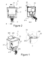
- the present invention relates to cooling devices having a dispenser with a compartment wherein water or beverage can be filled through a fill opening.
- Cooling devices generally comprise two parts namely a cooler part and/or a freezer part.
- the cooling part retards the spoiling of foodstuff disposed therein and preserves foodstuff.
- the freezer part provides freezing of the foodstuff disposed therein by keeping the temperature of inside at zero degrees or lower than zero degrees.
- Containers in shelf and container form, can be adapted to the inner part of the cooling device door.
- the door of the cooling device can also be utilized as storage regions for the storage of foodstuff or beverages.
- there are cooling devices having a dispenser which can dispense water, beverage or icy water without opening the door thereof. They can be dispensed through the dispenser by means a fluid valve. Since the valve member is accessible through an outer wall of a door of the cooling device, dispensing is realized without the need for opening the door.
- the dispenser is adapted onto an inner wall of the door so as to remain inside the cooling device.
- the dispenser is provided to exist within a heat insulated housing of the cooling device and the water or the beverage is provided to be cooled.
- the water, coming from the dispenser, is dispensed by turning on the valve when desired with the help of a dispense channel provided on the cooling device door and opened towards the inner wall from the outer wall.
- One each grooves are formed on the inner and outer walls of the door, which are connected to each other by means of the dispense channel.
- a tank of the dispenser wherein water is stored, is positioned in an inner groove provided on the inner wall such that a valve/dispense opening is placed to the dispense channel.
- the position of the groove provided on the inner wall determines the position where the dispenser is fixed.
- An outer groove is formed on the outer wall thereof providing access to the valve member.
- both grooves are at a position on the door where the user can easily access without the need for bending of the user.
- On the base part of the outer groove provided on the outer wall of the door there is a tray so as to correspond under the valve member. After a glass is put on the tray, the valve member is turned on, and beverage/water can be filled to the glass. At the same time, thanks to the grid form of the tray, the overflowing water is able to pass through the grid and can be accumulated in the tray part.
- the invention is a portable water dispensing module mounted to a refrigerator door inner liner.
- the inner liner has side walls with aligned vertically spaced module supports.
- the water dispensing module comprises a reservoir having a fill compartment located above a main reservoir.
- the fill compartment has a lid that has an opening closed by a cap.
- the invention relates to improvements to a water dispensing device mounted in the refrigerator doors, according to which a single opening is provided in the container which provides a part of the dispenser device, said container being completely sealed and hermetic.
- the single opening is sealed by a closure device which is also completely sealed and hermetic and provided with a single air inlet and provided internally with an air filtration system.
- the object of the present invention is to provide that the dispenser container, which is adapted to the door at a position between the shelves on the cooling device door, can be accessed from the top so that the dispenser can be filled without being removed.
- the present invention is a cooling device having a heat insulated body; a door hinged to the body; a container adapted to an inner wall of the door.
- the cooling device comprises a lid having a platform guiding to the fill water in a manner providing to fill the water from a fill opening to the inside of the container and connected to a cover of the container in a manner covering the fill opening.
- a shelf is positioned on the container in order for the volume, provided on the inner wall of the cooling device door, to be utilized in an efficient manner. Because of the shelf, the opening and closing movement of the lid is delimited which guides water filling on the cover. Since the lid is guiding the water filling, filling is realized in an easy manner without water splashing around or without overflowing.
- the container is an outer tank of a dispenser having a valve member.
- the filled water can also be dispensed.
- a barrier is formed at a vertical direction to the platform and at both sides of the platform of the lid.
- a handle is formed on the platform of the lid in a manner to provide opening the lid.
- a person can open the lid by means of a single movement of his/her finger.
- a depression is formed on the cover providing a position to the fill opening.
- an elevation difference is formed with respect to the cover surface, and by means of this, overflow of the water from the cover to the outside is prevented while water is being filled, since while water is being filled, it flows inwardly after hitting the side walls of the depression.
- the depression is a place the lid is to be connected thereto, it facilitates the connection of the lid to the cover.
- a pin is formed on a lateral wall of the depression in a manner to provide mounting the lid to the cover.
- the lid can be connected to the cover from a support point thereof.
- a stopper is formed on a lateral wall of the depression with cylindrical extension shaped.
- a hole is formed on the barrier of the lid in a manner to provide the lid pivoted in the hole with the pin connection.
- the pin is fixed to a hole wherein the lid can be pivoted.
- a guide rail in a semi-circular opening shape is formed on the barrier of the lid in a manner to provide the stopper act and stop.
- the lid is stopped at a point after it is opened in an angled manner at a certain distance.
- a passageway is provided in a manner to provide the pin to pass into the hole with sliding over the barrier and formed as recess shaped on the outer surface of the barrier of the lid.
- the pin reaches the hole after passing through the recess thanks to the recessed form of the passageway.
- a shelf adapted to the inner wall in a manner to provide a distance letting the lid open, between the container.
- the volume of the inner wall of the cooling device door is utilized.
- an ⁇ angle of the opened lid on the cover of the container is a wide angle.
- the fill opening can be accessed by opening the lid at a wide angle.
- a wheeling movement is provided to let the lid open and close pivoted with the pin connected to the hole.
- the lid can be opened in an easy manner forwardly in a connected manner to the cover.
- the cooling device comprising a lid geometrically formed as a funnel. Especially said funnel or channel is closed in its circumference. So this lid is like a shaft. When filling water in the tank water slopping over the lid is avoided. Further the lid is mechanically more stable.
- a handle on the lid is an end stop contacting an outer cover edge in an open position of the lid.
- the open position of the lid is therefore fixed and no further open of the lid will arise.
- the lid is strut at the outer edge of the cover in the open position.
- Figure 1 the rear perspective view of the subject matter dispenser, having a lid on a cover thereof, is given, where the lid of the dispenser is in open position.
- Cross section B-B is the longitudinal cross sectional view of the dispenser illustrated in Figure 2 .
- Detail C is the cross sectional view illustrating the lid in open position, taken from cross section B-B.
- Detail D is the detailed view of a pin hole provided on the lid, taken from Figure 3 .
- Detail E is the detailed view of a pin embodied on a side wall of a depression of the cover, taken from Figure 3 .
- Detail G is the detailed view of a guide and a pin hole on the lid, taken from Figure 4 .
- Detail F is the detailed view of a stopper and of a pin embodied on a side wall of a depression of the cover, taken from Figure 4 .
- Cross section H-H is a cross sectional view of the lid on the cover where the lid is in closed position and taken from Figure 5 .
- Detail I is the cross sectional view of the part supporting the lid on the cover and of the pin, hole, stopper and guide in this part, taken from cross section H-H.
- Detail K is the detailed view of a stopper and of a pin embodied on a side wall of a depression of the cover.
- Cross section J-J is a cross section on the cover where the lid is in half open position, taken from Figure 7 .
- Detail L is the detailed view illustrating the position of the pin and stopper inside the hole and the guide while the lid is in half-open position, taken from cross section J-J.
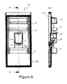
- Cross section A-A is the longitudinal cross section taken from Figure 8 and where the lid is in open position in order to fill the dispenser.
- Cross section N-N is the longitudinal cross section of a door illustrated in Figure 10 without the subject matter dispenser thereon.
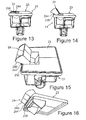
- FIG. 13 a perspective side view of another embodiment of a container of the dispenser with a closed lid is schown.
- FIG 14 a perspective side view of the container in Figure 13 with a open lid is schown.
- Figure 16 a perspective view of a cover with the lid of the container is shown.
- the present invention relates to a cooling device 1 having a dispenser 2 with a lid 24 provided on a cover 23 accessible for filling water from outside and adapted onto an inner wall 100 or onto a door 10 of the cooling device 1.
- the tank part of the dispenser 2 wherein water is filled is a container 21 in rectangular shape.
- a cover 23 is covered onto an inlet part 212 of the container 21.
- a lid 24 is covered onto the fill opening 234 ( Figure 1 ).
- FIG 1 the rear perspective view of the subject matter dispenser 2, having a lid 24 on a cover 23 thereof, is given, where the lid 24 of the dispenser 2 is in open position.
- FIG 2 the rear two dimensional view of the subject matter dispenser 2, having a lid 24 on a cover 23 thereof, is given.
- Cross section B-B is the longitudinal cross sectional view of the dispenser 2 illustrated in Figure 2 .
- Detail C is the cross sectional view illustrating the lid 24 in open position, taken from cross section B-B.
- an integrated valve member 3 is placed to the dispense channel 104 through the inner wall 100 of the cooling device 1 door 10.
- the lid 24 has a platform 240 where the water will flow during the filling process and a barrier 241 positioned in a vertical manner with respect to the platform 240 and on both lateral sides of the platform 240.
- the barriers 241 prevent the water overflow from the lateral sides of the platform 240.
- FIG 3 the lateral perspective view of the cover 23 and of the lid 24 is given.
- the part of the cover 23 whereon the fill opening 234 is formed is obtained by means of a depression 230 by embodying a depression form on the cover 23.
- the fill opening 234 is formed by cutting out some part of the depression 230 from the middle.
- a lateral wall 231 is formed on both sides of the depression 230.
- Detail E is the detailed view of a pin 232 embodied on a side wall 231 of a depression 230 of the cover 23, taken from Figure 3 .
- the pin 232 is in the form of a cylindrical protrusion.
- Detail D is the detailed view of a hole 242 for the pin 232 provided on the lid 24, taken from Figure 3 .
- a passageway 245 is formed in the part of the barrier 241 where the hole 242 is provided and which is in the form of a recess formed towards the hole 242.
- a handle 244 on the lid 24 embodied on the upper part of the platform 240 and in a vertical manner with respect to the platform 240.
- the lid 24 is opened by means of a pivotal movement.
- FIG 4 the lateral perspective view of a cover 23 in an alternative embodiment of the present invention is given.
- Detail G is the detailed view of a guide rail 243 and a hole 242 for the pin 232 on the lid 24, taken from Figure 4 .
- Detail F is the detailed view of a stopper 233 and of a pin 232 embodied on a side wall 231 of a depression 230 of the cover 23, taken from Figure 4 .
- the stopper 233 is formed on the front part of the pin 232 and on the side wall 231 of the depression 230 in order for the lid 24 to be opened up to a certain point and to be stopped at that point.
- the guide rail 243 embodied on the barrier 241 of the lid 24 is positioned under the hole 242 and is in the form of a semi-circular opening.
- the hole 242 is in the form of a circular opening. While the pin 232 is engaging to the hole 242 and the stopper 233 engages to the guide rail 243. During opening of the lid 24, the stopper 233 is rested into the guide rail 243 and to an end point of the guide rail 243 and provides the lid 24 to remain open at a certain distance.
- a passageway 245 is embodied in the form of a recess on the barrier 241 and in the middle of the guide rail 243 and of the hole 242.
- Cross section H-H is a cross sectional view of the lid 24 on the cover 23 where the lid 24 is in closed position and taken from Figure 5 .
- Detail I is the cross sectional view of the part supporting the lid 24 on the cover 23 and of the pin 232, hole 242, stopper 233 and guide rail 243 in this part, taken from cross section H-H.
- Detail K is the detailed view of a stopper 233 and of a pin 232 embodied on a side wall 231 of a depression 230 of the cover 23.
- FIG 7 the lateral perspective view of a cover 23 is given where the lid 24 is in half-open position.
- Cross section J-J is a cross section on the cover 23 where the lid 24 is in half open position, taken from Figure 7 .
- Detail L is the detailed view illustrating the position of the pin 232 and stopper 233 inside the hole 242 and the guide rail 243 while the lid 24 is in half-open position, taken from cross section J-J.
- a passageway 245 is formed by cutting out this part of the barrier 241.
- FIG 8 the rear two dimensional view of a cooling device 1 door 10 having a dispenser 2 adapted to an inner wall 100 of the door 10 is given, where the dispenser 2 is passed through the connection rails 105 provided on the side walls 211 of the container 21 and the inner wall 100 opposite thereto.
- Cross section A-A is the longitudinal cross section taken from Figure 8 and where the lid 24 is in open position in order to fill the dispenser 3.
- the dispenser 2 is seated onto a carrier 13 embodied on the inner wall 100 of a base 214 of the dispenser 2 ( Figure 8 , 9 , 11 ).
- the carrier 13 in the form of an "L"-like protrusion ( Figure 8 , 9 ).
- An inner groove 102 is formed in the middle part of the carrier 13. The adaptation of the dispenser (2) or the container 21 to the door 10 is performed by the engagement of the connection rails 105, 213 to each other and by taking the container 21 into the inner groove 102.
- FIG 9 the frontal perspective view of a cooling device 1 having a dispenser 2 adapted from an inner wall 100 of a door 10 is given.
- a door 10 is hinged to a heat insulated body 12 of the cooling device 1.
- the dispenser 2 is generally positioned at a determined position between the shelves 11 assembled to the inner wall 100 of the door 10.
- FIG 10 the frontal two dimensional view of the cooling device 1 door 10 having an outer groove 103 thereon is given.
- water distribution is provided with the help of a valve member 3 of the dispenser 2 in an accessible manner from an outer wall 101 of the door 10.
- the valve member 3 is adapted to a valve opening 210 of the container 21 ( Figure 1 ).
- Cross section N-N is the longitudinal cross section of a door 10 illustrated in Figure 10 without the subject matter dispenser 2 thereon.
- Figure 11 the perspective view of an inner groove 102 wherein the dispenser 2 container 21 is to be placed and formed on the inner wall 100 of the door 10 is given.
- FIG 12 the perspective view of the outer groove 103 providing access to the valve member 3 of the dispenser 2 and formed on the outer wall 101 of the door 10 is given.
- the outer groove 103 provides manual access to the valve member 3.
- the inner groove 102 determines the position of the dispenser 2 since the dispenser 2 is adapted. Therefore, the position of the inner groove 102 is at a position on the door 10 and in a manner that the user can easily access such that there is no need for bending of the user.
- the dispense channel 104 is beginning from the inner groove 102 and ends on the outer groove 103 and since the valve member 3 is passed through, it is formed on the door 10 for providing flow such that the inner groove 102 is at a higher position than the outer groove 103 ( Figure 10 , cross section N-N).
- a dispense channel 104 is embodied extending from the outer wall 101 towards the inner wall 100 on the cooling device 1 door 10 ( Figure 10 cross section N-N, Figure 11 and 12 ). During the adaptation of the dispenser 2 to the inner groove 102 of the door 10, the valve member 3 is passed through the dispense channel 104.
- the operation principle of the present invention is as follows. Since the dispenser 2 is adapted to the inner wall 100of the door 10 of the cooling device 1, the dispenser 2 container 21 is accessible when the door 10 is opened. Thus, water or beverage can be filled into the container 21. For this reason, filling is realized through a fill opening 234 provided on the cover 23 of the container 21. A lid 24 covering the fill opening 234 is opened by being held and lifted from the handle 244 thereof. The lid 24 is supported from the lateral walls 231 of the depression 230 provided on the cover 23. Thus, it receives support from a pin 232 and a corresponding hole 242 and it is opened by realizing a circular pivotal movement.
- the point at which it will stop is determined by the length of the opening of the semi-circular guide rail 243 since the stopper 233 is rested to an end point of the guide rail 243.
- a wide angled ( ⁇ ) opening is realized.
- the opening of the wide angle in important for providing accessibility of the user.
- the user brings the inlet part (not illustrated in the figures) of the bottle in his/her hand onto the platform 240 of the lid 24, and fills the inner side of the container 21 with water.
- the barriers 241 prevent overflow of the water.
- the platform 240 functions as a guide for water during the filling process. It provides filling of the water into the container 21 in an easy manner without overflow. After the water filling process, the lid 24 is closed.
- the dispenser 2 may have pluralities of containers 21 positioned telescopically. There may be a water filter inside the inner container 21.
- the dispenser 2 is a water dispenser; however, beverages other than water can be put therein.
- the container 21 may not be a member of a dispenser 2.
- the container 21 is a compartment with a bigger volume than the shelves 11 illustrated in the figure.
- the container 21 can be filled in an accessible manner without the need for removing it from the place thereof.
- the smallest distance in the inner volume of the door 10 is left for providing space saving. This distance y forms the movement space of the lid 24.
- the lid 24 is opened more or less than the wide angle ⁇ , there occurs a problem during the filling process and therefore, it has to be opened at an angle ⁇ .
- the distance y should be provided in between.
- the lid 24 can be connected in guide form to the side walls 231 so as to cover the fill opening 234 of the cover 23 and it can be opened and closed by means of the sliding movement with the guide.
- the guide embodied on the side wall 231 is in the form of a rail (not illustrated in the figure). Since the pins of the lid 24 at both sides are engaging to the rail, the sliding movement can be provided along the side walls 231 of the fill opening 234.
- an inclined water path (not illustrated in the figures) can be embodied on the platform 240 of the lid 24 functioning as a guide.
- the platform 240 is a planar structure; in the alternative embodiment, said inclined water path is a recessed water flow path formed in the middle of the planar platform 240.
- a further embodiment of a container 21 is shown in perspective side view.
- a lid 24 is formed which is designed as a shaft-like tunnel respectively as a funnel. Therefore, the lid 24 is formed as a circumferentially closed tube which enables the filling of water into the container 23 over the lid 24 without a slop occurs.
- the lid 24 is shown in closed condition in Figure 13 .
- a handle 44 is formed which also serves as a limit stop when the lid 24 is open.
- Figure 14 shows the opened condition of the lid 24.
- the lid 24 is thereby positioned inclined upwards and backwards. This opened position is held by the handle 244 which fits on an outer cover edge 235 of the cover and thus supports itself.
- FIG 16 a perspective view of a cover 23 with the opened lid 24 is shown.
Landscapes
- Engineering & Computer Science (AREA)
- Chemical & Material Sciences (AREA)
- Combustion & Propulsion (AREA)
- Physics & Mathematics (AREA)
- Mechanical Engineering (AREA)
- Thermal Sciences (AREA)
- General Engineering & Computer Science (AREA)
- Devices For Dispensing Beverages (AREA)
- Refrigerator Housings (AREA)
- Devices That Are Associated With Refrigeration Equipment (AREA)
Applications Claiming Priority (1)
| Application Number | Priority Date | Filing Date | Title |
|---|---|---|---|
| TR201209971 | 2012-08-31 |
Publications (3)
| Publication Number | Publication Date |
|---|---|
| EP2703755A2 true EP2703755A2 (fr) | 2014-03-05 |
| EP2703755A3 EP2703755A3 (fr) | 2014-07-16 |
| EP2703755B1 EP2703755B1 (fr) | 2016-08-31 |
Family
ID=47915597
Family Applications (1)
| Application Number | Title | Priority Date | Filing Date |
|---|---|---|---|
| EP13161073.5A Active EP2703755B1 (fr) | 2012-08-31 | 2013-03-26 | Dispositif de refroidissement comprenant un distributeur d'eau |
Country Status (3)
| Country | Link |
|---|---|
| EP (1) | EP2703755B1 (fr) |
| ES (1) | ES2600646T3 (fr) |
| PL (1) | PL2703755T3 (fr) |
Cited By (2)
| Publication number | Priority date | Publication date | Assignee | Title |
|---|---|---|---|---|
| CN105300019A (zh) * | 2015-11-24 | 2016-02-03 | 广东奥马电器股份有限公司 | 一种冰箱用饮水机结构 |
| US10233070B2 (en) | 2011-12-09 | 2019-03-19 | Electrolux Home Products, Inc. | Refrigerator with automatic liquid dispenser |
Citations (2)
| Publication number | Priority date | Publication date | Assignee | Title |
|---|---|---|---|---|
| US6574984B1 (en) | 2002-02-07 | 2003-06-10 | Camco Inc. | Refrigerator door mounted water dispensing assembly |
| WO2008035201A2 (fr) | 2006-09-21 | 2008-03-27 | BSH Bosch und Siemens Hausgeräte GmbH | Amélioration d'un dispositif de distribution d'eau logé dans la porte d'un appareil frigorifique |
Family Cites Families (3)
| Publication number | Priority date | Publication date | Assignee | Title |
|---|---|---|---|---|
| WO2007066958A1 (fr) * | 2005-12-06 | 2007-06-14 | Lg Electronics Inc. | Dispositif de fabrication de glace d'un refrigerateur, et refrigerateur possedant ce dispositif |
| KR100756450B1 (ko) * | 2006-06-23 | 2007-09-07 | 엘지전자 주식회사 | 냉장고용 물탱크 |
| KR101466659B1 (ko) * | 2007-11-20 | 2014-12-01 | 삼성전자 주식회사 | 디스펜서용 물탱크 및 이를 구비하는 냉장고 |
-
2013
- 2013-03-26 EP EP13161073.5A patent/EP2703755B1/fr active Active
- 2013-03-26 PL PL13161073T patent/PL2703755T3/pl unknown
- 2013-03-26 ES ES13161073.5T patent/ES2600646T3/es active Active
Patent Citations (2)
| Publication number | Priority date | Publication date | Assignee | Title |
|---|---|---|---|---|
| US6574984B1 (en) | 2002-02-07 | 2003-06-10 | Camco Inc. | Refrigerator door mounted water dispensing assembly |
| WO2008035201A2 (fr) | 2006-09-21 | 2008-03-27 | BSH Bosch und Siemens Hausgeräte GmbH | Amélioration d'un dispositif de distribution d'eau logé dans la porte d'un appareil frigorifique |
Cited By (2)
| Publication number | Priority date | Publication date | Assignee | Title |
|---|---|---|---|---|
| US10233070B2 (en) | 2011-12-09 | 2019-03-19 | Electrolux Home Products, Inc. | Refrigerator with automatic liquid dispenser |
| CN105300019A (zh) * | 2015-11-24 | 2016-02-03 | 广东奥马电器股份有限公司 | 一种冰箱用饮水机结构 |
Also Published As
| Publication number | Publication date |
|---|---|
| PL2703755T3 (pl) | 2017-01-31 |
| EP2703755B1 (fr) | 2016-08-31 |
| EP2703755A3 (fr) | 2014-07-16 |
| ES2600646T3 (es) | 2017-02-10 |
Similar Documents
| Publication | Publication Date | Title |
|---|---|---|
| US4143795A (en) | Refrigerator beverage dispensers | |
| US7076966B2 (en) | Refrigerated liquid dispensing system | |
| US9045260B2 (en) | Beverage dispensing system | |
| US9513049B2 (en) | Refrigerator with bottom mount freezer with multiple sliding drawers | |
| US20150040604A1 (en) | Refrigerator | |
| WO2017016768A1 (fr) | Réfrigérateur équipé d'un distributeur de glace/d'eau | |
| US3830406A (en) | Refrigerator dispensing container array | |
| EP2420778A2 (fr) | Réfrigérateur | |
| US20150107293A1 (en) | Portable Cooler Apparatus | |
| AU2004245587B2 (en) | Water reservoir for a refrigerator | |
| US9353982B2 (en) | Portable food and beverage storage and dispensing cooler | |
| EP2703755B1 (fr) | Dispositif de refroidissement comprenant un distributeur d'eau | |
| WO2013031149A2 (fr) | Réfrigérateur | |
| WO1999000320A1 (fr) | Distributeur de boisson | |
| WO2013098022A1 (fr) | Balconnet approprié pour être utilisé sur une porte de dispositif de refroidissement | |
| KR200319649Y1 (ko) | 다목적 냉장고 | |
| EP2730871B1 (fr) | Dispositif de refroidissement comportant un réservoir avec un couvercle | |
| CN102762938B (zh) | 包括制冰机的制冷装置 | |
| KR200171453Y1 (ko) | 냉장고의 병 가드 | |
| RU2336474C2 (ru) | Холодильное устройство | |
| EP4030129B1 (fr) | Appareil de refroidissement doté d'une unité de distribution d'eau | |
| US12410047B2 (en) | Bottom load water dispenser with an elongated dispensing area | |
| KR102012358B1 (ko) | 냉장고용 트레이 | |
| WO2006043246A1 (fr) | Distributeur de boissons | |
| KR200427785Y1 (ko) | 사용이 용이한 선반용 물통 |
Legal Events
| Date | Code | Title | Description |
|---|---|---|---|
| AK | Designated contracting states |
Kind code of ref document: A2 Designated state(s): AL AT BE BG CH CY CZ DE DK EE ES FI FR GB GR HR HU IE IS IT LI LT LU LV MC MK MT NL NO PL PT RO RS SE SI SK SM TR |
|
| AX | Request for extension of the european patent |
Extension state: BA ME |
|
| PUAI | Public reference made under article 153(3) epc to a published international application that has entered the european phase |
Free format text: ORIGINAL CODE: 0009012 |
|
| RIN1 | Information on inventor provided before grant (corrected) |
Inventor name: EICHER, MAX Inventor name: STAUD, RALPH Inventor name: KARA, CANER Inventor name: TISCHER, THOMAS Inventor name: ALT, RENE Inventor name: KLEINLEIN, PHILIPP Inventor name: HARTWEIN, CHRISTINE Inventor name: BECKE, CHRISTOPH Inventor name: KESSLER, ANDREAS Inventor name: DAGCI, OEZKAN |
|
| PUAL | Search report despatched |
Free format text: ORIGINAL CODE: 0009013 |
|
| AK | Designated contracting states |
Kind code of ref document: A3 Designated state(s): AL AT BE BG CH CY CZ DE DK EE ES FI FR GB GR HR HU IE IS IT LI LT LU LV MC MK MT NL NO PL PT RO RS SE SI SK SM TR |
|
| AX | Request for extension of the european patent |
Extension state: BA ME |
|
| RIC1 | Information provided on ipc code assigned before grant |
Ipc: F25D 23/12 20060101AFI20140606BHEP |
|
| 17P | Request for examination filed |
Effective date: 20150116 |
|
| RBV | Designated contracting states (corrected) |
Designated state(s): AL AT BE BG CH CY CZ DE DK EE ES FI FR GB GR HR HU IE IS IT LI LT LU LV MC MK MT NL NO PL PT RO RS SE SI SK SM TR |
|
| RAP1 | Party data changed (applicant data changed or rights of an application transferred) |
Owner name: BSH HAUSGERAETE GMBH |
|
| GRAP | Despatch of communication of intention to grant a patent |
Free format text: ORIGINAL CODE: EPIDOSNIGR1 |
|
| INTG | Intention to grant announced |
Effective date: 20160411 |
|
| GRAS | Grant fee paid |
Free format text: ORIGINAL CODE: EPIDOSNIGR3 |
|
| GRAA | (expected) grant |
Free format text: ORIGINAL CODE: 0009210 |
|
| AK | Designated contracting states |
Kind code of ref document: B1 Designated state(s): AL AT BE BG CH CY CZ DE DK EE ES FI FR GB GR HR HU IE IS IT LI LT LU LV MC MK MT NL NO PL PT RO RS SE SI SK SM TR |
|
| REG | Reference to a national code |
Ref country code: CH Ref legal event code: EP Ref country code: GB Ref legal event code: FG4D |
|
| REG | Reference to a national code |
Ref country code: IE Ref legal event code: FG4D |
|
| REG | Reference to a national code |
Ref country code: DE Ref legal event code: R096 Ref document number: 602013010826 Country of ref document: DE |
|
| REG | Reference to a national code |
Ref country code: AT Ref legal event code: REF Ref document number: 825364 Country of ref document: AT Kind code of ref document: T Effective date: 20161015 |
|
| REG | Reference to a national code |
Ref country code: LT Ref legal event code: MG4D |
|
| REG | Reference to a national code |
Ref country code: NL Ref legal event code: MP Effective date: 20160831 |
|
| REG | Reference to a national code |
Ref country code: AT Ref legal event code: MK05 Ref document number: 825364 Country of ref document: AT Kind code of ref document: T Effective date: 20160831 |
|
| PG25 | Lapsed in a contracting state [announced via postgrant information from national office to epo] |
Ref country code: NO Free format text: LAPSE BECAUSE OF FAILURE TO SUBMIT A TRANSLATION OF THE DESCRIPTION OR TO PAY THE FEE WITHIN THE PRESCRIBED TIME-LIMIT Effective date: 20161130 Ref country code: RS Free format text: LAPSE BECAUSE OF FAILURE TO SUBMIT A TRANSLATION OF THE DESCRIPTION OR TO PAY THE FEE WITHIN THE PRESCRIBED TIME-LIMIT Effective date: 20160831 Ref country code: LT Free format text: LAPSE BECAUSE OF FAILURE TO SUBMIT A TRANSLATION OF THE DESCRIPTION OR TO PAY THE FEE WITHIN THE PRESCRIBED TIME-LIMIT Effective date: 20160831 Ref country code: HR Free format text: LAPSE BECAUSE OF FAILURE TO SUBMIT A TRANSLATION OF THE DESCRIPTION OR TO PAY THE FEE WITHIN THE PRESCRIBED TIME-LIMIT Effective date: 20160831 Ref country code: FI Free format text: LAPSE BECAUSE OF FAILURE TO SUBMIT A TRANSLATION OF THE DESCRIPTION OR TO PAY THE FEE WITHIN THE PRESCRIBED TIME-LIMIT Effective date: 20160831 |
|
| REG | Reference to a national code |
Ref country code: ES Ref legal event code: FG2A Ref document number: 2600646 Country of ref document: ES Kind code of ref document: T3 Effective date: 20170210 |
|
| PG25 | Lapsed in a contracting state [announced via postgrant information from national office to epo] |
Ref country code: NL Free format text: LAPSE BECAUSE OF FAILURE TO SUBMIT A TRANSLATION OF THE DESCRIPTION OR TO PAY THE FEE WITHIN THE PRESCRIBED TIME-LIMIT Effective date: 20160831 Ref country code: AT Free format text: LAPSE BECAUSE OF FAILURE TO SUBMIT A TRANSLATION OF THE DESCRIPTION OR TO PAY THE FEE WITHIN THE PRESCRIBED TIME-LIMIT Effective date: 20160831 Ref country code: GR Free format text: LAPSE BECAUSE OF FAILURE TO SUBMIT A TRANSLATION OF THE DESCRIPTION OR TO PAY THE FEE WITHIN THE PRESCRIBED TIME-LIMIT Effective date: 20161201 Ref country code: LV Free format text: LAPSE BECAUSE OF FAILURE TO SUBMIT A TRANSLATION OF THE DESCRIPTION OR TO PAY THE FEE WITHIN THE PRESCRIBED TIME-LIMIT Effective date: 20160831 Ref country code: SE Free format text: LAPSE BECAUSE OF FAILURE TO SUBMIT A TRANSLATION OF THE DESCRIPTION OR TO PAY THE FEE WITHIN THE PRESCRIBED TIME-LIMIT Effective date: 20160831 |
|
| PG25 | Lapsed in a contracting state [announced via postgrant information from national office to epo] |
Ref country code: EE Free format text: LAPSE BECAUSE OF FAILURE TO SUBMIT A TRANSLATION OF THE DESCRIPTION OR TO PAY THE FEE WITHIN THE PRESCRIBED TIME-LIMIT Effective date: 20160831 Ref country code: RO Free format text: LAPSE BECAUSE OF FAILURE TO SUBMIT A TRANSLATION OF THE DESCRIPTION OR TO PAY THE FEE WITHIN THE PRESCRIBED TIME-LIMIT Effective date: 20160831 |
|
| PG25 | Lapsed in a contracting state [announced via postgrant information from national office to epo] |
Ref country code: BE Free format text: LAPSE BECAUSE OF FAILURE TO SUBMIT A TRANSLATION OF THE DESCRIPTION OR TO PAY THE FEE WITHIN THE PRESCRIBED TIME-LIMIT Effective date: 20160831 Ref country code: PT Free format text: LAPSE BECAUSE OF FAILURE TO SUBMIT A TRANSLATION OF THE DESCRIPTION OR TO PAY THE FEE WITHIN THE PRESCRIBED TIME-LIMIT Effective date: 20170102 Ref country code: SK Free format text: LAPSE BECAUSE OF FAILURE TO SUBMIT A TRANSLATION OF THE DESCRIPTION OR TO PAY THE FEE WITHIN THE PRESCRIBED TIME-LIMIT Effective date: 20160831 Ref country code: CZ Free format text: LAPSE BECAUSE OF FAILURE TO SUBMIT A TRANSLATION OF THE DESCRIPTION OR TO PAY THE FEE WITHIN THE PRESCRIBED TIME-LIMIT Effective date: 20160831 Ref country code: DK Free format text: LAPSE BECAUSE OF FAILURE TO SUBMIT A TRANSLATION OF THE DESCRIPTION OR TO PAY THE FEE WITHIN THE PRESCRIBED TIME-LIMIT Effective date: 20160831 Ref country code: SM Free format text: LAPSE BECAUSE OF FAILURE TO SUBMIT A TRANSLATION OF THE DESCRIPTION OR TO PAY THE FEE WITHIN THE PRESCRIBED TIME-LIMIT Effective date: 20160831 Ref country code: BG Free format text: LAPSE BECAUSE OF FAILURE TO SUBMIT A TRANSLATION OF THE DESCRIPTION OR TO PAY THE FEE WITHIN THE PRESCRIBED TIME-LIMIT Effective date: 20161130 |
|
| REG | Reference to a national code |
Ref country code: DE Ref legal event code: R097 Ref document number: 602013010826 Country of ref document: DE |
|
| PLBE | No opposition filed within time limit |
Free format text: ORIGINAL CODE: 0009261 |
|
| STAA | Information on the status of an ep patent application or granted ep patent |
Free format text: STATUS: NO OPPOSITION FILED WITHIN TIME LIMIT |
|
| 26N | No opposition filed |
Effective date: 20170601 |
|
| PG25 | Lapsed in a contracting state [announced via postgrant information from national office to epo] |
Ref country code: SI Free format text: LAPSE BECAUSE OF FAILURE TO SUBMIT A TRANSLATION OF THE DESCRIPTION OR TO PAY THE FEE WITHIN THE PRESCRIBED TIME-LIMIT Effective date: 20160831 |
|
| REG | Reference to a national code |
Ref country code: CH Ref legal event code: PL |
|
| GBPC | Gb: european patent ceased through non-payment of renewal fee |
Effective date: 20170326 |
|
| PG25 | Lapsed in a contracting state [announced via postgrant information from national office to epo] |
Ref country code: MC Free format text: LAPSE BECAUSE OF FAILURE TO SUBMIT A TRANSLATION OF THE DESCRIPTION OR TO PAY THE FEE WITHIN THE PRESCRIBED TIME-LIMIT Effective date: 20160831 |
|
| REG | Reference to a national code |
Ref country code: IE Ref legal event code: MM4A |
|
| REG | Reference to a national code |
Ref country code: FR Ref legal event code: ST Effective date: 20171130 |
|
| PG25 | Lapsed in a contracting state [announced via postgrant information from national office to epo] |
Ref country code: FR Free format text: LAPSE BECAUSE OF NON-PAYMENT OF DUE FEES Effective date: 20170331 Ref country code: LU Free format text: LAPSE BECAUSE OF NON-PAYMENT OF DUE FEES Effective date: 20170326 |
|
| PG25 | Lapsed in a contracting state [announced via postgrant information from national office to epo] |
Ref country code: IE Free format text: LAPSE BECAUSE OF NON-PAYMENT OF DUE FEES Effective date: 20170326 Ref country code: GB Free format text: LAPSE BECAUSE OF NON-PAYMENT OF DUE FEES Effective date: 20170326 Ref country code: CH Free format text: LAPSE BECAUSE OF NON-PAYMENT OF DUE FEES Effective date: 20170331 Ref country code: LI Free format text: LAPSE BECAUSE OF NON-PAYMENT OF DUE FEES Effective date: 20170331 |
|
| PGFP | Annual fee paid to national office [announced via postgrant information from national office to epo] |
Ref country code: ES Payment date: 20180423 Year of fee payment: 6 |
|
| PG25 | Lapsed in a contracting state [announced via postgrant information from national office to epo] |
Ref country code: MT Free format text: LAPSE BECAUSE OF NON-PAYMENT OF DUE FEES Effective date: 20170326 |
|
| PG25 | Lapsed in a contracting state [announced via postgrant information from national office to epo] |
Ref country code: AL Free format text: LAPSE BECAUSE OF FAILURE TO SUBMIT A TRANSLATION OF THE DESCRIPTION OR TO PAY THE FEE WITHIN THE PRESCRIBED TIME-LIMIT Effective date: 20160831 |
|
| PG25 | Lapsed in a contracting state [announced via postgrant information from national office to epo] |
Ref country code: HU Free format text: LAPSE BECAUSE OF FAILURE TO SUBMIT A TRANSLATION OF THE DESCRIPTION OR TO PAY THE FEE WITHIN THE PRESCRIBED TIME-LIMIT; INVALID AB INITIO Effective date: 20130326 |
|
| PG25 | Lapsed in a contracting state [announced via postgrant information from national office to epo] |
Ref country code: CY Free format text: LAPSE BECAUSE OF NON-PAYMENT OF DUE FEES Effective date: 20160831 |
|
| PG25 | Lapsed in a contracting state [announced via postgrant information from national office to epo] |
Ref country code: MK Free format text: LAPSE BECAUSE OF FAILURE TO SUBMIT A TRANSLATION OF THE DESCRIPTION OR TO PAY THE FEE WITHIN THE PRESCRIBED TIME-LIMIT Effective date: 20160831 |
|
| REG | Reference to a national code |
Ref country code: ES Ref legal event code: FD2A Effective date: 20200728 |
|
| PG25 | Lapsed in a contracting state [announced via postgrant information from national office to epo] |
Ref country code: IS Free format text: LAPSE BECAUSE OF FAILURE TO SUBMIT A TRANSLATION OF THE DESCRIPTION OR TO PAY THE FEE WITHIN THE PRESCRIBED TIME-LIMIT Effective date: 20161231 |
|
| PG25 | Lapsed in a contracting state [announced via postgrant information from national office to epo] |
Ref country code: ES Free format text: LAPSE BECAUSE OF NON-PAYMENT OF DUE FEES Effective date: 20190327 |
|
| PGFP | Annual fee paid to national office [announced via postgrant information from national office to epo] |
Ref country code: IT Payment date: 20250331 Year of fee payment: 13 |
|
| PGFP | Annual fee paid to national office [announced via postgrant information from national office to epo] |
Ref country code: DE Payment date: 20260331 Year of fee payment: 14 |
|
| PGFP | Annual fee paid to national office [announced via postgrant information from national office to epo] |
Ref country code: TR Payment date: 20260324 Year of fee payment: 14 |
|
| PGFP | Annual fee paid to national office [announced via postgrant information from national office to epo] |
Ref country code: PL Payment date: 20260313 Year of fee payment: 14 |