EP2703852B2 - Nappe de guidage de lumière avec couplage d'entrée et dioptre à surface de fresnel - Google Patents
Nappe de guidage de lumière avec couplage d'entrée et dioptre à surface de fresnel Download PDFInfo
- Publication number
- EP2703852B2 EP2703852B2 EP13178471.2A EP13178471A EP2703852B2 EP 2703852 B2 EP2703852 B2 EP 2703852B2 EP 13178471 A EP13178471 A EP 13178471A EP 2703852 B2 EP2703852 B2 EP 2703852B2
- Authority
- EP
- European Patent Office
- Prior art keywords
- guide
- face
- rays
- light
- reflection
- Prior art date
- Legal status (The legal status is an assumption and is not a legal conclusion. Google has not performed a legal analysis and makes no representation as to the accuracy of the status listed.)
- Active
Links
Images

Classifications
-
- G—PHYSICS
- G02—OPTICS
- G02B—OPTICAL ELEMENTS, SYSTEMS OR APPARATUS
- G02B6/00—Light guides; Structural details of arrangements comprising light guides and other optical elements, e.g. couplings
- G02B6/0001—Light guides; Structural details of arrangements comprising light guides and other optical elements, e.g. couplings specially adapted for lighting devices or systems
- G02B6/0011—Light guides; Structural details of arrangements comprising light guides and other optical elements, e.g. couplings specially adapted for lighting devices or systems the light guides being planar or of plate-like form
- G02B6/0013—Means for improving the coupling-in of light from the light source into the light guide
- G02B6/0015—Means for improving the coupling-in of light from the light source into the light guide provided on the surface of the light guide or in the bulk of it
- G02B6/002—Means for improving the coupling-in of light from the light source into the light guide provided on the surface of the light guide or in the bulk of it by shaping at least a portion of the light guide, e.g. with collimating, focussing or diverging surfaces
- G02B6/0021—Means for improving the coupling-in of light from the light source into the light guide provided on the surface of the light guide or in the bulk of it by shaping at least a portion of the light guide, e.g. with collimating, focussing or diverging surfaces for housing at least a part of the light source, e.g. by forming holes or recesses
-
- F—MECHANICAL ENGINEERING; LIGHTING; HEATING; WEAPONS; BLASTING
- F21—LIGHTING
- F21S—NON-PORTABLE LIGHTING DEVICES; SYSTEMS THEREOF; VEHICLE LIGHTING DEVICES SPECIALLY ADAPTED FOR VEHICLE EXTERIORS
- F21S41/00—Illuminating devices specially adapted for vehicle exteriors, e.g. headlamps
- F21S41/10—Illuminating devices specially adapted for vehicle exteriors, e.g. headlamps characterised by the light source
- F21S41/14—Illuminating devices specially adapted for vehicle exteriors, e.g. headlamps characterised by the light source characterised by the type of light source
- F21S41/141—Light emitting diodes [LED]
- F21S41/143—Light emitting diodes [LED] the main emission direction of the LED being parallel to the optical axis of the illuminating device
-
- F—MECHANICAL ENGINEERING; LIGHTING; HEATING; WEAPONS; BLASTING
- F21—LIGHTING
- F21S—NON-PORTABLE LIGHTING DEVICES; SYSTEMS THEREOF; VEHICLE LIGHTING DEVICES SPECIALLY ADAPTED FOR VEHICLE EXTERIORS
- F21S41/00—Illuminating devices specially adapted for vehicle exteriors, e.g. headlamps
- F21S41/20—Illuminating devices specially adapted for vehicle exteriors, e.g. headlamps characterised by refractors, transparent cover plates, light guides or filters
- F21S41/24—Light guides
-
- F—MECHANICAL ENGINEERING; LIGHTING; HEATING; WEAPONS; BLASTING
- F21—LIGHTING
- F21S—NON-PORTABLE LIGHTING DEVICES; SYSTEMS THEREOF; VEHICLE LIGHTING DEVICES SPECIALLY ADAPTED FOR VEHICLE EXTERIORS
- F21S43/00—Signalling devices specially adapted for vehicle exteriors, e.g. brake lamps, direction indicator lights or reversing lights
- F21S43/20—Signalling devices specially adapted for vehicle exteriors, e.g. brake lamps, direction indicator lights or reversing lights characterised by refractors, transparent cover plates, light guides or filters
- F21S43/235—Light guides
- F21S43/236—Light guides characterised by the shape of the light guide
- F21S43/239—Light guides characterised by the shape of the light guide plate-shaped
-
- F—MECHANICAL ENGINEERING; LIGHTING; HEATING; WEAPONS; BLASTING
- F21—LIGHTING
- F21S—NON-PORTABLE LIGHTING DEVICES; SYSTEMS THEREOF; VEHICLE LIGHTING DEVICES SPECIALLY ADAPTED FOR VEHICLE EXTERIORS
- F21S43/00—Signalling devices specially adapted for vehicle exteriors, e.g. brake lamps, direction indicator lights or reversing lights
- F21S43/20—Signalling devices specially adapted for vehicle exteriors, e.g. brake lamps, direction indicator lights or reversing lights characterised by refractors, transparent cover plates, light guides or filters
- F21S43/235—Light guides
- F21S43/242—Light guides characterised by the emission area
- F21S43/243—Light guides characterised by the emission area emitting light from one or more of its extremities
-
- F—MECHANICAL ENGINEERING; LIGHTING; HEATING; WEAPONS; BLASTING
- F21—LIGHTING
- F21S—NON-PORTABLE LIGHTING DEVICES; SYSTEMS THEREOF; VEHICLE LIGHTING DEVICES SPECIALLY ADAPTED FOR VEHICLE EXTERIORS
- F21S43/00—Signalling devices specially adapted for vehicle exteriors, e.g. brake lamps, direction indicator lights or reversing lights
- F21S43/20—Signalling devices specially adapted for vehicle exteriors, e.g. brake lamps, direction indicator lights or reversing lights characterised by refractors, transparent cover plates, light guides or filters
- F21S43/235—Light guides
- F21S43/249—Light guides with two or more light sources being coupled into the light guide
-
- G—PHYSICS
- G02—OPTICS
- G02B—OPTICAL ELEMENTS, SYSTEMS OR APPARATUS
- G02B6/00—Light guides; Structural details of arrangements comprising light guides and other optical elements, e.g. couplings
- G02B6/0001—Light guides; Structural details of arrangements comprising light guides and other optical elements, e.g. couplings specially adapted for lighting devices or systems
- G02B6/0011—Light guides; Structural details of arrangements comprising light guides and other optical elements, e.g. couplings specially adapted for lighting devices or systems the light guides being planar or of plate-like form
- G02B6/0013—Means for improving the coupling-in of light from the light source into the light guide
- G02B6/0015—Means for improving the coupling-in of light from the light source into the light guide provided on the surface of the light guide or in the bulk of it
- G02B6/0016—Grooves, prisms, gratings, scattering particles or rough surfaces
-
- G—PHYSICS
- G02—OPTICS
- G02B—OPTICAL ELEMENTS, SYSTEMS OR APPARATUS
- G02B6/00—Light guides; Structural details of arrangements comprising light guides and other optical elements, e.g. couplings
- G02B6/0001—Light guides; Structural details of arrangements comprising light guides and other optical elements, e.g. couplings specially adapted for lighting devices or systems
- G02B6/0011—Light guides; Structural details of arrangements comprising light guides and other optical elements, e.g. couplings specially adapted for lighting devices or systems the light guides being planar or of plate-like form
- G02B6/0013—Means for improving the coupling-in of light from the light source into the light guide
- G02B6/0015—Means for improving the coupling-in of light from the light source into the light guide provided on the surface of the light guide or in the bulk of it
- G02B6/0018—Redirecting means on the surface of the light guide
-
- F—MECHANICAL ENGINEERING; LIGHTING; HEATING; WEAPONS; BLASTING
- F21—LIGHTING
- F21S—NON-PORTABLE LIGHTING DEVICES; SYSTEMS THEREOF; VEHICLE LIGHTING DEVICES SPECIALLY ADAPTED FOR VEHICLE EXTERIORS
- F21S43/00—Signalling devices specially adapted for vehicle exteriors, e.g. brake lamps, direction indicator lights or reversing lights
- F21S43/10—Signalling devices specially adapted for vehicle exteriors, e.g. brake lamps, direction indicator lights or reversing lights characterised by the light source
- F21S43/13—Signalling devices specially adapted for vehicle exteriors, e.g. brake lamps, direction indicator lights or reversing lights characterised by the light source characterised by the type of light source
- F21S43/14—Light emitting diodes [LED]
Definitions
- the invention relates to a light guide in particular for a module and a lighting and / or signaling device, in particular for a motor vehicle.
- the invention also relates to a module and to a lighting and / or signaling device equipped with the light guide in question.
- An optical guide is, very schematically, an elongated element made of transparent material. It can have a generally circular section. The light rays usually enter there by one of the ends and propagate by total reflection in the length of the guide in the direction of its opposite end. Part of the rays can exit via prismatic zones on its outer surface.
- An optical guide may also have an essentially flat or extended shape, typically with a section close to a rectangular shape. This type of guide is commonly referred to as a guide sheet or a flat guide. In this type of optical guide, the light rays can be collimated in the thickness of the guide and propagate by transmission without reflection to an exit face or to a reflection face and then an exit face.
- Light guides can emit light over their entire length. They also have the advantage of being able to take a wide variety of geometric shapes, be rectilinear or in an arc, and provide an illuminating surface even in areas that are not easily accessible from the headlamp or the vehicle light. They thus strongly participate in the style of the projector or fire.
- the patent document FR 2 904 093 A1 relates to a lighting or signaling device in particular for a motor vehicle, comprising a curved guide ply.
- the guide ply forms a portion of a spherical cap and comprises a series of light sources arranged in orifices arranged along its circumference. It includes a reflective rear face with parabolic profile and a front ray exit face.
- the light rays emitted by the light sources thus propagate along the guide by successive reflections on its guide surfaces according to the principle of total reflection when the angle incidence is greater than a limit angle.
- the rays meet the rear surface, they are reflected towards the front of the guide and propagate to the front exit surface, then exit the guide and form a light or signaling beam.
- the outlet face is generally planar with a general profile in an arc.
- the curve of the guide ply is generally circular so as to be able to surround a lighting module.
- the tablecloth is also quite thin.
- the guide ply of this teaching is in fact not really suited to reduced radii of curvature and / or to greater ply thicknesses. Indeed, in areas of significant curvature and more particularly of significant thickness, the light rays propagating by successive reflection according to the principle of total reflection risk encountering one of the guide surfaces at an angle of incidence less than the angle d 'limit incidence and thus exit the guide. Such rays do not participate in the illumination beam so that dark portions of the beam appear at these areas of significant curvature.
- the patent document FR 2 941 785 A1 also relates to a lighting or signaling device in particular for a motor vehicle, comprising a curved guide ply.
- the front exit face of the sheet has a non-planar shape and the rear reflection face is dimensioned to reflect the rays adequately towards the exit face.
- the light rays emitted by the light sources propagate along the guide by successive reflections on its guide surfaces according to the principle of total reflection when the angle of incidence is greater than a limit angle .
- the patent document FR 2 943 118 A1 relates to a lighting or signaling device in particular for a motor vehicle, comprising a guide ply. More particularly, this teaching relates to a device for coupling the guide ply.
- This coupling device is in fact a portion of the sheet intended to ensure the coupling between a light source and the sheet. It essentially comprises a reflection surface with complex shape arranged on the guide surface which is opposite to the light source. This reflection surface is configured to reflect a first part of the rays emitted by the light source, and this directly towards the front face of the guide and a second part towards the rear reflection face.
- the first part of the spokes corresponds to a reduced sector, typically less than or equal to 20 ° while the second part of the rays usually covers a sector of more than 180 °.
- the coupler is configured so that the rays propagating in the sheet are essentially collimated in its thickness. In the event of a significant curvature of the sheet, some of the rays coming from the coupler and directed towards the rear reflection face may meet one of the guide surfaces of the sheet before meeting the reflection face. Given the large angle of incidence, these rays will be reflected and their trajectory will be modified. This then results in a loss of quality of the beam emitted by a reduction in its homogeneity.
- the patent application EP 1895228 proposes the realization of a projector device allowing to have a light guide aspect to realize new concepts of style in different traffic lights and lighting, comprising an exit zone, an entry zone with an optical system for collimating the light rays coming from a light source and a central zone with another optical system to collimate the light rays collimated by the optical system from the entry zone.
- the structure and the shape of this optical system of the entry zone is not optimized to ensure the collimation of the light rays coming from the light source according to planes parallel to the mean planes of the guide, which causes a reduction in the effectiveness of the light guide.
- the object of the invention is to propose a solution to at least one of the above-mentioned drawbacks. More particularly, the object of the invention is to propose a light guide capable of describing a curvature along a reduced radius and / or of substantial thickness without, however, exhibiting any noticeable inhomogeneity in the curved portion. More particularly still, the invention also aims to propose a light guide, in particular of the tablecloth type, with reduced dimensions.
- the subject of the invention is a light guide made of transparent material, as defined in claim 1, comprising: an entry face of the light rays emitted by a light source; an exit face of the light rays; refraction means located on the optical path of a fraction of the light rays propagating between the entry face and the exit face, and configured so as to collimate said fraction of light rays passing through said means.
- the guide comprises means of coupling with the light source capable of collimating, preferably exclusively, in the thickness of the guide the rays entering through the entry face.
- the refraction means comprise a diopter with a Fresnel surface.
- the entry face is preferably at least essentially planar.
- the outlet face is preferably at least essentially planar.
- the refraction means are crossed only by the aforementioned fraction of the light rays propagating between the entry face and the exit face, another fraction of said light rays being collimated by a parabolic reflection face of the guide.
- the fraction of the light rays passing through the refraction means can correspond to more than 20%, preferably 30%, more preferably 40% of the light flux propagating in the guide from the light source.
- the other fraction of the light rays collimated by a parabolic reflection face of the guide may correspond to more than 20%, preferably 30%, more preferably 40% of the light flux.
- the light guide comprises several similar reflection faces extending successively along the exit face, thus forming a repeating pattern.
- the light guide is generally flat with a given thickness and collimation by the refractive means and / or by the parabolic reflection face is carried out, preferably exclusively, in planes parallel to the mean plane of the guide.
- the parabolic reflection face extends symmetrically on either side of the inlet face, the refraction means being arranged on a portion of the guide extending between the inlet face and the face outlet and whose width preferably corresponds to that of the inlet face.
- the refraction means are separate and / or remote from the coupling means.
- the coupling means comprise a cavity on the entry face at the focal point of the parabolic profile of the reflection surface, the cavity comprising a surface of revolution capable of refracting the rays coming from the light source located in the cavity and meeting it, so as to collimate them in the thickness of the guide.
- the coupling means comprise a reflection surface on at least one of the faces of the guide forming its thickness, said surface being a surface of revolution capable of reflecting the rays coming from a light source located in the cavity and the meeting, so as to collimate them in the thickness of the guide.
- the surface of the cavity has a general diabolo shape over at least 150 °, preferably over essentially 180 °, and the reflection surface on one or each of the faces of the guide forming its thickness has a general cone shape centered on the axis of revolution of the surface of the cavity.
- the transparent material of the guide has a first refractive index n 1 and the refraction means comprise two diopters formed by a volume inside the guide of a second refractive index n 2 different from, preferably less than, the refractive index n 1 of the guide, said volume preferably being air.
- the volume of the second refractive index n 2 forms a first diopter of circular profile centered on the entry face and a second diopter with Fresnel surface generally parallel to the first, the first and second diopters being successively crossed by the light rays.
- the refraction means are located on a portion of the guide corresponding to the first half of the guide from the inlet face to the outlet face.
- the refraction means extend over the majority, preferably over the entire thickness of the guide.
- the invention also relates to a lighting and / or signaling device comprising a light guide and at least one light source, remarkable in that the light guide conforms to the invention.
- the measures of the invention make it possible to produce a light guide with coupling means of reduced size.
- a central fraction of the rays is indeed collimated by refraction means located between the entry face and the exit face, the rest of the rays can then be collimated by other means such as, for example, by a reflecting face. parabolic extending on either side of the central fraction of the rays.
- the first collimating in the thickness of the guide provided by the coupling means allows the rays to propagate by transmission and, therefore, to use greater ply thicknesses.
- the compactness makes it possible to further discretize the light guide with small patterns.
- the guide thus allows the guide to have profiles with small radii of curvature, each pattern remaining essentially flat, the curvature being ensured at the junctions between the patterns.
- the discretization of the guide thus allows it to ensure uniformity of lighting while being able to follow reduced radii of curvature and / or while having a significant thickness.
- FIG. 1 to 3 illustrate a first embodiment of the invention.
- a light guide part 2 extends in a longitudinal direction which corresponds to a substantially horizontal direction on the figure 1 .
- Guide 2 is generally flat, that is to say with two generally parallel faces, one corresponding to an upper face and the other corresponding to a lower face with reference to the orientation of the guide on the figure 1 .
- Such a guide is commonly called a guide ply. It is made of solid transparent material such as polycarbonate. It includes a series of rear faces 4 with a parabolic profile and forming a repeating pattern along the guide. An input face 6 is provided in the middle of each rear face 4.
- the cavity 8 intended to receive a light source 10 in particular of the light-emitting diode type.
- the cavity is delimited by a surface of revolution about an axis 36 generally perpendicular to the mean plane of the guide or to the upper and lower faces of the guide forming its thickness, and included in the plane of the entry face 6.
- a surface of reflection 12 with an essentially V-shaped profile is provided on each of the upper and lower faces of the guide. The axes of revolution of these two surfaces 12 coincide with the axis of revolution of the surface of the cavity 8.
- the surface of the cavity 8 and the reflection surfaces 12 are configured to refract and reflect, respectively, the light rays emitted by the light source so as to collimate them in the thickness of the guide, that is to say so that they propagate in the guide in directions parallel to the mean plane of the guide.
- the guide 2 also includes refraction means with a volume of air 16 passing through its thickness.
- This volume of air constitutes two diopters 18 and 14.
- the first diopter 18 crossed by the rays coming from the entry face is of generally circular profile centered on the axis of revolution 36 of the reflection surfaces 12 and of the surface of the cavity 8. The rays are therefore incident therein at an essentially zero angle. They are therefore not refracted and pass through this diopter and the air volume without noticeable deviation.
- the second diopter 14 has a Fresnel profile configured to collimate the rays passing through it in planes parallel to the mean plane of the guide in a direction corresponding to the optical axis 34 of the guide, more precisely the optical axis 34 of the pattern of the guide. This direction can be generally perpendicular to the outlet face 32 so that the rays passing through the outlet face are not deflected.
- the figure 2 is a transparent view of the rear part of a pattern of guide 2 of the figure 1 , illustrating the coupling means to the input face and the collimation in the thickness of the guide. Indeed, it can be observed that the rays 20 emitted by the light source (not shown in the figure 2 for reasons of clarity) and meeting the surface of revolution 81 of the cavity 8 are refracted so as to propagate in planes parallel to the mean plane of the guide.
- the surface of the cavity can be easily calculated according to the law of Snell-Descartes, similar to a convex lens.
- the rays 22 and 24 emitted by the light source and meeting the semicircular surfaces 82 and 83 of the cavity 8 are refracted there and are then reflected by the reflection surfaces 12, so as to also propagate in planes parallel to the mean plane of the guide.
- the profile of the reflection surfaces can thus resemble a parabola whose focal point corresponds to the center of the light source. This parabolic profile can however be corrected in particular by calculation due to the refraction undergone by the rays passing through the semi-circular surfaces of the cavity 8.
- the reflection on the reflection surfaces 82 and 83 is preferably carried out by application of the principle of total reflection .
- the spokes 20, 22 and 24 are thus collimated in the thickness of the guide or, in other words, collimated in planes perpendicular to the hub plane of the guide and passing through the light source.
- the majority, preferably more than 80% of the light rays emitted by the light source in the cavity are thus collimated in the thickness of the guide.
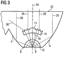
- the figure 3 is an elevation view of one of the guide portions of the Figures 1 and 2 , illustrating the collimation of the rays in planes parallel to the mean plane of the guide.
- the light rays 28 which form a fraction of the light rays meet the diopters 18 and 14 and are deflected in parallel planes so as to be thus fully collimated, that is to say parallel to each other and to the optical axis 34 of the guide.
- This fraction of the rays corresponds to a sector of the rays propagating in the guide from the light source, this sector being centered on the optical axis 34 of the guide and corresponding to the rays which meet the first and second diopters 18 and 14.
- These diopters are formed by a volume of air 16 on the optical path of the rays in the guide and having a refractive index n 2 close to 1 and therefore lower than the refractive index n 1 of the solid material forming the guide (of 1.58 for polycarbonate).
- the first diopter 18 at the interface between the material of the guide and the air volume 16 has a generally circular profile centered on the axis of revolution of the surface of the cavity 8 and of the reflection surfaces 12, so as not to not deflect the rays crossing it.
- the second diopter has a Fresnel surface capable of refracting and collimating the rays coming from a focal point corresponding to the light source, in the manner of a converging lens.
- Certain rays such as ray 30 meeting one of the bonding surfaces of the Fresnel surface are deflected laterally in an unwanted manner. These non-collimated rays constitute a minority of the rays crossing the diopters.
- the Fresnel lens and surface principle is well known to those skilled in the art and is not further detailed.
- the other rays 26 thus forming another fraction of the rays propagating in the guide from the light source, are mainly reflected by the parabolic reflection face 4 so as to be also collimated along the optical axis 34 of the guide.
- the parabolic profile of the reflection face is such that its focus essentially corresponds to the light source.
- the radii meet this face with an angle greater than the limiting angle of refraction, and consequently undergo a reflection in accordance with the principle of total reflection according to the law of Snell-Descartes.
- the reflecting face does not need to be provided with a reflecting coating.
- the rays emitted by the light source in particular from a light source of the electroluminescence diode type illuminating essentially in a half-space directed towards the entry face, are guided towards the guide and collimated only in the thickness of the guide . They can thus be propagated there by transmission radially with respect to the axis 36 of the light source. Thanks to the refraction means formed by the air volume 16 and the first and second diopters 18 and 14, a fraction of these rays collimated in the thickness of the guide is then collimated in a perpendicular direction so as to be completely collimated according to the optical axis.
- the other fraction of the rays is reflected and collimated in the same direction so as to be also totally collimated along the optical axis.
- This construction thus makes it possible to obtain a collimated beam with a very reduced geometry. Indeed, the distance between the entry face and the exit face can be reduced and, moreover, the volume of air forming two diopters can be thin.
- the use of a Fresnel surface is also particularly advantageous in this compactness logic.
- the refraction means could comprise, instead of the volume of air described above, an insert made of a transparent material other than that of the guide or at least having a different refractive index so as to form the diopters.
- the diopters can take other forms.
- the first diopter may not be circular or cylindrical, so as to deviate in a controlled manner at least part of the rays.
- the second diopter may not be on the Fresnel surface. Indeed, a profile of the concave type similar to that of a lens can be envisaged as a function of the space available, it being understood that the use of a Fresnel surface is particularly advantageous from a point of view of size and compactness.
Landscapes
- Physics & Mathematics (AREA)
- Engineering & Computer Science (AREA)
- Optics & Photonics (AREA)
- General Engineering & Computer Science (AREA)
- General Physics & Mathematics (AREA)
- Microelectronics & Electronic Packaging (AREA)
- Planar Illumination Modules (AREA)
Description
- L'invention a trait à un guide de lumière notamment pour module et dispositif d'éclairage et/ou de signalisation, notamment pour véhicule automobile. L'invention a trait également à un module et à un dispositif d'éclairage et/ou de signalisation équipé du guide de lumière en question.
- Dans le domaine de l'éclairage et de la signalisation de véhicules automobiles, il est de plus en plus fréquent d'utiliser des guides de lumière ou guides optiques. Un guide optique est, très schématiquement, un élément allongé en matière transparente. Il peut présenter une section généralement circulaire. Les rayons lumineux y entrent habituellement par une des extrémités et se propagent par réflexion totale dans la longueur du guide en direction de son extrémité opposée. Une partie des rayons peut sortir via des zones prismatiques à sa surface extérieure. Un guide optique peut également présenter une forme essentiellement plate ou étendue, typiquement avec une section proche d'une forme rectangulaire. Ce type de guide est couramment désigné nappe de guidage ou encore guide plat. Dans ce type de guide optique, les rayons lumineux peuvent être collimatés dans l'épaisseur du guide et se propager par transmission sans réflexion jusqu'à une face de sortie ou jusqu'à une face de réflexion puis une face de sortie.
- Les guides optiques peuvent émettre de la lumière sur toute leur longueur. Ils présentent également l'avantage de pouvoir prendre des formes géométriques très variées, être rectilignes ou en arc de cercle, et amener une surface éclairante même dans des zones peu accessibles du projecteur ou du feu du véhicule. Ils participent ainsi fortement au style du projecteur ou du feu.
- Le document de brevet
FR 2 904 093 A1 - Le document de brevet
FR 2 941 785 A1 - Le document de brevet
FR 2 943 118 A1 - La demande de brevet
EP 1895228 propose la réalisation d'un dispositif projecteur permettant d'avoir un aspect guide de lumière pour réaliser de nouveaux concepts de style dans différents feux de signalisation et d'éclairage, comprenant une zone de sortie, une zone d'entrée avec un système optique pour collimater les rayons lumineux provenant d'une source lumineuse et une zone centrale avec un autre système optique pour collimater les rayons lumineux collimatés par le système optique de la zone d'entrée. Néanmoins, la structure et la forme de ce système optique de la zone d'entrée n'est pas optimisé pour assurer la collimation des rayons lumineux provenant de la source lumineuse selon des plans parallèles au plans moyen du guide, ce qui cause une diminution de l'efficacité du guide de lumière. - L'invention a pour objectif de proposer une solution à au moins un des inconvénients sus mentionnés. Plus particulièrement, l'invention a pour objectif de proposer un guide de lumière apte à décrire une courbure selon un rayon réduit et/ou d'épaisseur importante sans pour autant présenter d'inhomogénéité notoire à la portion courbée. Plus particulièrement encore, l'invention a également pour objectif de proposer un guide de lumière, notamment du type nappe, avec des dimensions réduites.
- L'invention a pour objet un guide de lumière en matériau transparent, tel que défini dans la revendication 1, comprenant: une face d'entrée des rayons lumineux émis par une source lumineuse; une face de sortie des rayons lumineux; des moyens de réfraction situés sur le chemin optique d'une fraction des rayons lumineux se propageant entre la face d'entrée et la face de sortie, et configurés de manière à collimater ladite fraction de rayons lumineux traversant lesdits moyens.
- Selon l'invention, le guide comprend des moyens de couplage avec la source lumineuse aptes à collimater, préférentiellement exclusivement, dans l'épaisseur du guide les rayons entrant par la face d'entrée.
- Selon un mode avantageux de l'invention, les moyens de réfraction comprennent un dioptre avec surface de Fresnel.
- La face d'entrée est préférentiellement au moins essentiellement plane. La face de sortie est préférentiellement au moins essentiellement plane.
- Selon l'invention, les moyens de réfraction ne sont traversés que par la fraction sus mentionnée des rayons lumineux se propageant entre la face d'entrée et la face de sortie, une autre fraction desdits rayons lumineux étant collimatée par une face de réflexion parabolique du guide.
- La fraction des rayons lumineux traversant les moyens de réfraction peut correspondre à plus de 20%, préférentiellement 30%, plus préférentiellement 40% du flux lumineux se propageant dans le guide depuis la source lumineuse. L'autre fraction des rayons lumineux collimatée par une face de réflexion parabolique du guide peut correspondre à plus de 20%, préférentiellement 30%, plus préférentiellement 40% du flux lumineux.
- Selon l'invention, le guide de lumière comprend plusieurs faces de réflexion similaires s'étendant successivement le long de la face de sortie, formant ainsi un motif répétitif.
- Selon un encore autre mode avantageux de l'invention, le guide de lumière est généralement plat avec une épaisseur donnée et la collimation par les moyens de réfraction et/ou par la face de réflexion parabolique est opérée, préférentiellement exclusivement, dans des plans parallèles au plan moyen du guide.
- Selon l'invention, la face de réflexion parabolique s'étend symétriquement de part et d'autre de la face d'entrée, les moyens de réfraction étant disposés sur une portion du guide s'étendant entre la face d'entrée et la face de sortie et dont la largeur correspond préférentiellement à celle de la face d'entrée.
- Les moyens de réfraction sont distincts et/ou à distance des moyens de couplage.
- Selon l'invention, les moyens de couplage comprennent une cavité sur la face d'entrée au niveau du foyer du profil parabolique de la surface de réflexion, la cavité comprenant une surface de révolution apte à réfracter les rayons provenant de la source lumineuse située dans la cavité et la rencontrant, de manière à les collimater dans l'épaisseur du guide.
- Selon l'invention, les moyens de couplage comprennent une surface de réflexion sur au moins une des faces du guide formant son épaisseur, ladite surface étant une surface de révolution apte à réfléchir les rayons provenant d'une source lumineuse située dans la cavité et la rencontrant, de manière à les collimater dans l'épaisseur du guide.
- Selon un encore autre mode avantageux de l'invention, la surface de la cavité a une forme générale de diabolo sur au moins 150°, préférentiellement sur essentiellement 180°, et la surface de réflexion sur une ou chacune des faces du guide formant son épaisseur a une forme générale de cône centré sur l'axe de révolution de la surface de la cavité.
- Selon l'invention, le matériau transparent du guide est d'un premier indice de réfraction n1 et les moyens de réfraction comprennent deux dioptres formés par un volume à l'intérieur du guide d'un deuxième indice de réfraction n2 différent de, préférentiellement inférieur à, l'indice de réfraction n1 du guide, ledit volume étant préférentiellement de l'air.
- Selon un encore autre mode avantageux de l'invention, le volume du deuxième indice de réfraction n2 forme un premier dioptre de profil circulaire centré sur la face d'entrée et un deuxième dioptre avec surface de Fresnel généralement parallèle au premier, les premier et deuxième dioptres étant successivement traversés par les rayons lumineux.
- Selon un encore autre mode avantageux de l'invention, les moyens de réfraction sont situés sur une portion du guide correspondant à la première moitié du guide de la face d'entrée vers la face de sortie.
- Selon un encore autre mode avantageux de l'invention, les moyens de réfraction s'étendent sur la majorité, préférentiellement sur la totalité de l'épaisseur du guide.
- L'invention a également pour objet un dispositif d'éclairage et/ou de signalisation comprenant un guide lumière et au moins une source lumineuse, remarquable en ce que le guide de lumière est conforme à l'invention.
- Les mesures de l'invention permettent de réaliser une guide de lumière avec des moyens de couplage de taille réduite. Une fraction centrale des rayons est en effet collimatée par des moyens de réfraction situés entre la face d'entrée et la face de sortie, le reste des rayons pouvant alors être collimaté par d'autres moyens tels que, par exemple, par une face réfléchissante parabolique s'étendant de part et d'autre de la fraction centrale des rayons. Dans le cas d'une nappe de guidage, le premier collimatage dans l'épaisseur du guide assuré par les moyens de couplage permet aux rayons de se propager par transmission et, partant, d'utiliser des épaisseurs de nappe plus importantes. La compacité permet de discrétiser davantage le guide de lumière avec des motifs de petite taille. Elle permet ainsi au guide d'avoir des profils avec de faibles rayons de courbure, chaque motif restant essentiellement plat, la courbure étant assurée au niveau de jonctions entre les motifs. La discrétisation du guide lui permet ainsi d'assurer une homogénéité d'éclairage tout en pouvant suivre des rayons de courbure réduits et/ou tout en ayant une épaisseur importante.
- D'autres caractéristiques et avantages de la présente invention seront mieux compris à l'aide de la description et des dessins parmi lesquels :
- la
figure 1 est une vue en perspective d'un guide de lumière selon un premier mode de réalisation de l'invention ; - la
figure 2 est une illustration d'une portion du guide de la lumière de lafigure 1 , illustrant la collimation des rayons dans l'épaisseur de la nappe ; - la
figure 3 est une vue en élévation d'une portion du guide de lumière de lafigure 1 , illustrant la collimation des rayons dans le plan de la nappe. - Les
figures 1 à 3 illustrent un premier mode de réalisation de l'invention. A lafigure 1 , on peut observer une représentation en perspective d'une partie de guide de lumière 2. Ce dernier s'étend selon une direction longitudinale qui correspond à une direction essentiellement horizontale sur lafigure 1 . Le guide 2 est généralement plat, c'est-à-dire avec deux faces généralement parallèles, l'une correspondant à une face supérieure et l'autre correspondant à une face inférieure en référence à l'orientation du guide sur lafigure 1 . Un tel guide est communément appelé nappe de guidage. Il est en matériau transparent solide tel que du polycarbonate. Il comprend une série de faces arrière 4 à profil parabolique et formant un motif répétitif le long du guide. Une face d'entrée 6 est prévue au milieu de chaque face arrière 4. Elle comprend une cavité 8 destinée à recevoir une source lumineuse 10 notamment du type diode à électroluminescence. La cavité est délimitée par une surface de révolution autour d'un axe 36 généralement perpendiculaire au plan moyen du guide ou aux faces supérieure et inférieure du guide formant son épaisseur, et compris dans le plan de la face d'entrée 6. Une surface de réflexion 12 à profil essentiellement en V est prévue sur chacune des faces supérieure et inférieure du guide. Les axes de révolution de ces deux surfaces 12 sont confondus avec l'axe de révolution de la surface de la cavité 8. La surface de la cavité 8 et les surfaces de réflexion 12 sont configurées pour réfracter et réfléchir, respectivement, les rayons lumineux émis par la source lumineuse de manière à les collimater dans l'épaisseur du guide, c'est-à-dire de manière à ce qu'ils se propagent dans le guide selon des directions parallèles au plan moyen du guide. - Le guide 2 comprend également des moyens de réfraction avec un volume d'air 16 traversant son épaisseur. Ce volume d'air constitue deux dioptres 18 et 14. Le premier dioptre 18 traversé par les rayons provenant de la face d'entrée est de profil généralement circulaire centré sur l'axe de révolution 36 des surfaces de réflexion 12 et de la surface de la cavité 8. Les rayons y sont donc incidents selon un angle essentiellement nul. Ils ne sont donc pas réfractés et traversent ce dioptre et le volume d'air sans déviation notoire. Le deuxième dioptre 14 a un profil de Fresnel configuré pour collimater les rayons le traversant dans des plans parallèles au plan moyen du guide suivant une direction correspondant à l'axe optique 34 du guide, plus précisément l'axe optique 34 du motif du guide. Cette direction peut être généralement perpendiculaire à la face de sortie 32 de manière à ce que les rayons traversant la face de sortie ne soient pas déviés.
- La
figure 2 est une vue en transparence de la partie arrière d'un motif du guide 2 de lafigure 1 , illustrant les moyens de couplage à la face d'entrée et la collimation dans l'épaisseur du guide. En effet, on peut observer que les rayons 20 émis par la source lumineuse (non représentée à lafigure 2 pour des raisons de clarté) et rencontrant la surface de révolution 81 de la cavité 8 sont réfractés de manière à se propager dans des plans parallèles au plan moyen du guide. La surface de la cavité peut être facilement calculée en application de la loi de Snell-Descartes, similairement à une lentille convexe. On peut également observer que les rayons 22 et 24 émis par la source lumineuse et rencontrant les surfaces demi-circulaires 82 et 83 de la cavité 8 y sont réfractés et sont ensuite réfléchis par les surfaces de réflexion 12, de manière à se propager également dans des plans parallèles au plan moyen du guide. Le profil des surfaces de réflexion peut ainsi s'apparenter à une parabole dont le foyer correspond au centre de la source lumineuse. Ce profil parabolique peut toutefois être corrigé notamment par calcul en raison de la réfraction subie par les rayons traversant les surfaces demi-circulaires de la cavité 8. La réflexion sur les surfaces de réflexion 82 et 83 est préférentiellement opérée par application du principe de réflexion totale. - Les rayons 20, 22 et 24 sont ainsi collimatés dans l'épaisseur du guide ou, autrement dit, collimatés dans des plans perpendiculaires au plan moyeu du guide et passant par la source lumineuse. La majorité, préférentiellement plus de 80% des rayons lumineux émis par la source lumineuse dans la cavité sont ainsi collimatés dans l'épaisseur du guide.
- La
figure 3 est une vue en élévation d'une des portions de guide desfigures 1 et 2 , illustrant la collimation des rayons dans des plans parallèles au plan moyen du guide. On peut en effet observer que les rayons lumineux 28 qui forment une fraction des rayons lumineux rencontrent les dioptres 18 et 14 et sont déviés dans des plans parallèles de manière à être ainsi totalement collimatés, c'est-à-dire parallèles entre eux et à l'axe optique 34 du guide. En effet, cette fraction des rayons correspond à un secteur des rayons se propageant dans le guide depuis la source lumineuse, ce secteur étant centré sur l'axe optique 34 du guide et correspondant aux rayons qui rencontrent les premier et deuxième dioptres 18 et 14. Ces dioptres sont formés par un volume d'air 16 sur le chemin optique des rayons dans le guide et présentant un indice de réfraction n2 proche de 1 et donc inférieur à l'indice de réfraction n1 du matériau solide formant le guide (de l'ordre de 1.58 pour du polycarbonate). Le premier dioptre 18 à l'interface entre le matériau du guide et le volume d'air 16 présente un profil généralement circulaire centré sur l'axe de révolution de la surface de la cavité 8 et des surfaces de réflexion 12, de manière à ne pas dévier les rayons le traversant. Le deuxième dioptre a une surface de Fresnel apte à réfracter et collimater les rayons provenant d'un foyer correspondant à la source lumineuse, à la manière d'une lentille convergente. Certains rayons tels que le rayon 30 rencontrant une des surfaces de liaison de la surface de Fresnel sont déviés latéralement de manière non désirée. Ces rayons non collimatés constituent une minorité des rayons traversant les dioptres. Le principe de lentille et de surface de Fresnel est bien connu en soi de l'homme de métier et n'est pas davantage détaillé. - Les autres rayons 26 formant ainsi une autre fraction des rayons se propageant dans le guide depuis la source lumineuse, sont majoritairement réfléchis par la face de réflexion parabolique 4 de manière à être également collimatés selon l'axe optique 34 du guide. Le profil parabolique de la face de réflexion est tel que son foyer correspond essentiellement à la source lumineuse. De plus, en fonction de la géométrie du guide, les rayons rencontrent cette face avec un angle supérieur à l'angle limite de réfraction, et subissent par conséquent une réflexion conformément au principe de réflexion totale selon la loi de Snell-Descartes. Dans ce cas, la face de réflexion n'a pas besoin d'être pourvue d'un revêtement réfléchissant.
- Grâce aux moyens de couplage qui ont été détaillés en relation avec la
figure 2 , les rayons émis par la source lumineuse, en particulier d'une source lumineuse du type diode à électroluminescence éclairant essentiellement dans un demi-espace dirigé vers la face d'entrée, sont guidé vers le guide et collimatés uniquement dans l'épaisseur du guide. Ils peuvent ainsi s'y propager par transmission radialement par rapport à l'axe 36 de la source lumineuse. Grâce aux moyens de réfraction formés par le volume d'air 16 et les premier et deuxième dioptres 18 et 14, une fraction de ces rayons collimatés dans l'épaisseur du guide est ensuite collimatée dans une direction perpendiculaire de manière à être totalement collimatés suivant l'axe optique. L'autre fraction des rayons est réfléchie et collimatée dans une même direction de manière à être également totalement collimatés suivant l'axe optique. Cette construction permet ainsi d'obtenir un faisceau collimaté avec une géométrie très réduite. En effet, la distance entre la face d'entrée et la face de sortie peut être réduite et, de plus, le volume d'air formant deux dioptres peut être mince. L'utilisation d'une surface de Fresnel est également particulièrement avantageuse dans cette logique de compacité. - Il est à noter que les moyens de réfraction pourraient comprendre, au lieu du volume d'air décrit ci-avant, un insert en un matériau transparent autre que celui du guide ou du moins ayant un indice de réfraction différent de manière former les dioptres. Indépendamment du matériau transparent remplissant le volume des moyens de réfraction, il est également à noter que les dioptres peuvent prendre d'autres formes. Le premier dioptre peut ne pas être circulaire ou cylindrique, de manière à dévier de manière contrôlée au moins une partie des rayons. Le deuxième dioptre peut ne pas être à surface de Fresnel. En effet, un profil du type concave similaire à celui d'une lentille peut être envisagé en fonction de la place disponible étant entendu que l'utilisation d'une surface de Fresnel est particulièrement intéressante d'un point de vue taille et compacité.
Claims (6)
- Guide de lumière (2) en matériau transparent, comprenant:- une face d'entrée (6) des rayons lumineux émis par une source lumineuse (10) ;- une face de sortie (32) des rayons lumineux ;- au moins deux faces de réflexion (4) paraboliques similaires et s'étendant successivement le long de la face de sortie (32), formant ainsi un motif répétitif ;- des moyens de réfraction (14, 16, 18) situés sur le chemin optique d'une fraction des rayons lumineux se propageant entre la face d'entrée (6) et la face de sortie (32), et configurés de manière à collimater ladite fraction de rayons lumineux traversant lesdits moyens ;- des moyens de couplage (8, 12) avec la source lumineuse (10) aptes à collimater, préférentiellement exclusivement, dans l'épaisseur du guide les rayons entrant par la face d'entrée (6) ;caractérisé ce que les moyens de couplage comprennent une cavité (8) sur la face d'entrée (6) au niveau du foyer du profil parabolique de chaque face de réflexion (4), la cavité (8) comprenant une première surface de révolution (81) autour d'un axe (36) perpendiculaire au plan moyen du guide et compris dans un plan de la face d'entrée (6), la cavité (8) étant apte à réfracter les rayons provenant de la source lumineuse (10) située dans la cavité et rencontrant la première surface de révolution (81), de manière à collimater lesdits rayons dans l'épaisseur du guide dans des plans parallèles au plan moyen du guide ;
en ce que les moyens de couplage comprennent aussi une surface de réflexion (12) sur une ou chacune des faces du guide formant son épaisseur, la surface de réflexion étant une deuxième surface de révolution autour de l'axe (36) et ayant une forme de cône, de sorte que la surface de réflexion (12) est apte à réfléchir les rayons provenant de la source lumineuse (10) située dans la cavité et rencontrant la deuxième surface de révolution, de manière à collimater les rayons dans l'épaisseur du guide selon des directions parallèles au plan moyen du guide
en ce que les moyens de réfraction (14, 16, 18) ne sont traversés que par la fraction des rayons lumineux se propageant entre la face d'entrée (6) et la face de sortie (32), une autre fraction desdits rayons lumineux étant collimatée par l'une des faces de réflexion paraboliques (4) du guide ;
en ce que le matériau transparent du guide est d'un premier indice de réfraction et les moyens de réfraction (14, 16, 18) comprennent deux dioptres (14, 18) formés par un volume (16) à l'intérieur du guide d'un deuxième indice de réfraction n2 différent de, préférentiellement inférieur à, l'indice de réfraction n1 du guide, ledit volume étant préférentiellement de l'air ;
et en ce que chaque face de réflexion parabolique (4) s'étend symétriquement de part et d'autre de la face d'entrée (6), les moyens de réfraction (14, 16, 18) étant disposés sur une portion du guide s'étendant entre la face d'entrée (6) et la face de sortie (32) et dont la largeur correspond préférentiellement à celle de la face d'entrée (6). - Guide de lumière (2) selon la revendication 1, caractérisé en ce que les moyens de réfraction (14, 16, 18) comprennent un dioptre avec surface de Fresnel (14).
- Guide de lumière (2) selon l'une des revendications 1 ou 2, caractérisé en ce que le volume du deuxième indice de réfraction n2 forme un premier dioptre (18) de profil circulaire centré sur la face d'entrée et un deuxième dioptre (14) avec surface de Fresnel généralement parallèle au premier, les premier et deuxième dioptres (18, 14) étant successivement traversés par les rayons lumineux.
- Guide de lumière (2) selon l'une des revendications 1 à 3, caractérisé en ce que les moyens de réfraction (14, 16, 18) sont situés sur une portion du guide correspondant à la première moitié du guide de la face d'entrée vers la face de sortie.
- Guide de lumière (2 ; 102) selon l'une des revendications 1 à 4, caractérisé en ce que les moyens de réfraction (14, 16, 18) s'étendent sur la majorité, préférentiellement sur la totalité de l'épaisseur du guide.
- Dispositif d'éclairage et/ou de signalisation comprenant un guide lumière et au moins une source lumineuse, caractérisé en ce que le guide de lumière (2) est conforme à l'une des revendications 1 à 5.
Applications Claiming Priority (1)
| Application Number | Priority Date | Filing Date | Title |
|---|---|---|---|
| FR1258000A FR2994747B1 (fr) | 2012-08-27 | 2012-08-27 | Nappe de guidage de lumiere avec couplage d'entree et dioptre a surface de fresnel |
Publications (3)
| Publication Number | Publication Date |
|---|---|
| EP2703852A1 EP2703852A1 (fr) | 2014-03-05 |
| EP2703852B1 EP2703852B1 (fr) | 2016-12-14 |
| EP2703852B2 true EP2703852B2 (fr) | 2020-01-08 |
Family
ID=46963977
Family Applications (1)
| Application Number | Title | Priority Date | Filing Date |
|---|---|---|---|
| EP13178471.2A Active EP2703852B2 (fr) | 2012-08-27 | 2013-07-30 | Nappe de guidage de lumière avec couplage d'entrée et dioptre à surface de fresnel |
Country Status (2)
| Country | Link |
|---|---|
| EP (1) | EP2703852B2 (fr) |
| FR (1) | FR2994747B1 (fr) |
Families Citing this family (12)
| Publication number | Priority date | Publication date | Assignee | Title |
|---|---|---|---|---|
| DE102013107912B4 (de) * | 2013-07-24 | 2023-07-27 | HELLA GmbH & Co. KGaA | Beleuchtungsvorrichtung für Fahrzeuge |
| CN105546454A (zh) * | 2016-02-03 | 2016-05-04 | 宁波市龙嘉摩托车有限公司 | 一种防眩晕的led摩托车尾灯 |
| US20200292143A1 (en) * | 2016-03-21 | 2020-09-17 | Lumileds Llc | Lighting arrangement |
| AT519125B1 (de) * | 2017-01-20 | 2018-04-15 | Zkw Group Gmbh | Leuchtvorrichtung für einen Kraftfahrzeugscheinwerfer sowie Kraftfahrzeugscheinwerfer |
| FR3063337B1 (fr) * | 2017-02-28 | 2021-07-02 | Valeo Vision Belgique | Dispositif lumineux avec element optique avec dioptre interieur |
| DE102018112794A1 (de) | 2018-05-29 | 2019-12-05 | Automotive Lighting Reutlingen Gmbh | Lichtleiter für eine Kraftfahrzeugbeleuchtungseinrichtung |
| CN110657399B (zh) * | 2018-06-29 | 2025-11-04 | 法雷奥市光(中国)车灯有限公司 | 配光构件、照明或信号指示装置和机动车辆 |
| CN110285387B (zh) * | 2019-07-11 | 2024-12-06 | 马瑞利汽车零部件(芜湖)有限公司 | 一种汽车信号灯光学系统 |
| CN112984454A (zh) * | 2020-04-30 | 2021-06-18 | 华域视觉科技(上海)有限公司 | 车灯用光导体、远光照明模组及车灯 |
| CN112415808A (zh) * | 2020-11-11 | 2021-02-26 | 福州大学 | 一种内嵌Mini-LED光源的二维区域调光导光板 |
| US12117138B2 (en) * | 2022-06-14 | 2024-10-15 | Tyri International, Inc. | Beamshaping waveguide for headlights |
| FR3139617B1 (fr) * | 2022-09-12 | 2024-11-01 | Renault Sas | Dispositif lumineux pour véhicule automobile |
Citations (4)
| Publication number | Priority date | Publication date | Assignee | Title |
|---|---|---|---|---|
| DE102005005860A1 (de) † | 2004-02-10 | 2005-08-25 | Koito Manufacturing Co., Ltd. | Fahrzeugleuchteneinheit |
| DE202005010490U1 (de) † | 2005-07-04 | 2005-09-22 | Fer Fahrzeugelektrik Gmbh | Optikkörper |
| DE102005042523A1 (de) † | 2005-05-31 | 2006-12-07 | Osram Opto Semiconductors Gmbh | Beleuchtungseinrichtung |
| US7300185B1 (en) † | 2003-02-19 | 2007-11-27 | Opto Technology, Inc. | Quadrilateral symmetrical light source |
Family Cites Families (8)
| Publication number | Priority date | Publication date | Assignee | Title |
|---|---|---|---|---|
| DE10309451A1 (de) * | 2003-03-05 | 2004-09-16 | Hella Kg Hueck & Co. | Fahrzeugleuchte |
| FR2904093B1 (fr) | 2006-07-21 | 2008-10-10 | Valeo Vision Sa | Dispositif d'eclairage ou de signalisation comportant une nappe de guidage galbee |
| FR2905448B1 (fr) * | 2006-09-01 | 2015-05-01 | Valeo Vision | Dispositif d'eclairage ou de signalisation d'aspect guide de lumiere haute performance pour vehicule. |
| US8235556B2 (en) * | 2008-10-20 | 2012-08-07 | Reflexite Corporation | Condensing element, array, and methods thereof |
| FR2941785B1 (fr) | 2009-02-05 | 2011-04-15 | Valeo Vision Sas | Dispositif optique, notamment pour vehicule automobile, tel qu'un dispositif d'eclairage ou de signalisation |
| FR2943118B1 (fr) | 2009-03-12 | 2012-07-20 | Valeo Vision Sas | Dispositif optique, notamment pour vehicule automobile, tel qu'un dispositif d'eclairage ou de signalisation |
| FR2952163B1 (fr) * | 2009-11-02 | 2013-08-23 | Valeo Vision | Dispositif d'eclairage ou de signalisation pour vehicule automobile comprenant un guide de lumiere |
| DE102010046022B4 (de) * | 2010-09-18 | 2022-05-25 | Automotive Lighting Reutlingen Gmbh | Kraftfahrzeugbeleuchtungseinrichtung mit einem flächigen Lichtleiter |
-
2012
- 2012-08-27 FR FR1258000A patent/FR2994747B1/fr active Active
-
2013
- 2013-07-30 EP EP13178471.2A patent/EP2703852B2/fr active Active
Patent Citations (4)
| Publication number | Priority date | Publication date | Assignee | Title |
|---|---|---|---|---|
| US7300185B1 (en) † | 2003-02-19 | 2007-11-27 | Opto Technology, Inc. | Quadrilateral symmetrical light source |
| DE102005005860A1 (de) † | 2004-02-10 | 2005-08-25 | Koito Manufacturing Co., Ltd. | Fahrzeugleuchteneinheit |
| DE102005042523A1 (de) † | 2005-05-31 | 2006-12-07 | Osram Opto Semiconductors Gmbh | Beleuchtungseinrichtung |
| DE202005010490U1 (de) † | 2005-07-04 | 2005-09-22 | Fer Fahrzeugelektrik Gmbh | Optikkörper |
Also Published As
| Publication number | Publication date |
|---|---|
| EP2703852B1 (fr) | 2016-12-14 |
| FR2994747B1 (fr) | 2015-07-10 |
| EP2703852A1 (fr) | 2014-03-05 |
| FR2994747A1 (fr) | 2014-02-28 |
Similar Documents
| Publication | Publication Date | Title |
|---|---|---|
| EP2703852B1 (fr) | Nappe de guidage de lumière avec couplage d'entrée et dioptre à surface de fresnel | |
| EP3128226B1 (fr) | Module lumineux en matériau transparent avec deux faces de reflexion | |
| EP2230446B1 (fr) | Dispositif d'éclairage ou de signalisation pour véhicule automobile | |
| EP2865937B1 (fr) | Dispositif d'éclairage comportant un guide de rayons lumineux | |
| EP1881263B1 (fr) | Dispositif d'éclairage ou de signalisation comportant une nappe de guidage galbée | |
| EP2690349B1 (fr) | Guide de lumière pour un dispositif d'éclairage et/ou de signalisation de véhicule automobile | |
| EP2738453A1 (fr) | Guide de lumière pour un dispositif optique, notamment d'éclairage et/ou de signalisation | |
| FR2966224A1 (fr) | Dispositif d'eclairage ou de signalisation | |
| EP2607778A1 (fr) | Système d'éclairage pour projecteur notamment de véhicule automobile | |
| EP2999919B1 (fr) | Guide optique a motif reflechissant pour la propagation d'un faisceau lumineux | |
| EP2976569B1 (fr) | Module d'éclairage et/ou de signalisation pour véhicule automobile | |
| EP2713097B1 (fr) | Guide de lumière à profil courbe avec zone à dioptres de correction | |
| EP3141806B1 (fr) | Module lumineux en materiau transparent | |
| FR3048067A1 (fr) | Guides optiques superposes produisant differents motifs lumineux | |
| FR3019263A1 (fr) | Guide optique avec motifs prismatiques formant des dioptres galbes | |
| EP2302292A1 (fr) | Module optique avec plieuse formée par un dioptre matériau transparent/air | |
| FR2989471A1 (fr) | Guide optique pour dispositif d'emission de lumiere de vehicule automobile | |
| FR3056697A1 (fr) | Module d'eclairage automobile avec lentille a focale reglable | |
| EP4078025A1 (fr) | Guide de lumière avec face d'entrée de collimation partielle | |
| FR3054045B1 (fr) | Guide optique avec cones de rentree de lumiere | |
| EP4416015A1 (fr) | Système de projection de plusieurs faisceaux lumineux | |
| FR3133071A1 (fr) | Pièce optique avec plusieurs zones de sortie en série | |
| EP1715246A1 (fr) | Projecteur de véhicule automobile | |
| FR2906009A1 (fr) | Dispositif d'eclairage et/ou de signalisation pour vehicule automobile. | |
| FR3061777A1 (fr) | Coupleur multi sources lumineuses pour guide optique |
Legal Events
| Date | Code | Title | Description |
|---|---|---|---|
| AK | Designated contracting states |
Kind code of ref document: A1 Designated state(s): AL AT BE BG CH CY CZ DE DK EE ES FI FR GB GR HR HU IE IS IT LI LT LU LV MC MK MT NL NO PL PT RO RS SE SI SK SM TR |
|
| AX | Request for extension of the european patent |
Extension state: BA ME |
|
| PUAI | Public reference made under article 153(3) epc to a published international application that has entered the european phase |
Free format text: ORIGINAL CODE: 0009012 |
|
| 17P | Request for examination filed |
Effective date: 20140905 |
|
| RBV | Designated contracting states (corrected) |
Designated state(s): AL AT BE BG CH CY CZ DE DK EE ES FI FR GB GR HR HU IE IS IT LI LT LU LV MC MK MT NL NO PL PT RO RS SE SI SK SM TR |
|
| 17Q | First examination report despatched |
Effective date: 20150420 |
|
| GRAP | Despatch of communication of intention to grant a patent |
Free format text: ORIGINAL CODE: EPIDOSNIGR1 |
|
| INTG | Intention to grant announced |
Effective date: 20160719 |
|
| GRAS | Grant fee paid |
Free format text: ORIGINAL CODE: EPIDOSNIGR3 |
|
| GRAA | (expected) grant |
Free format text: ORIGINAL CODE: 0009210 |
|
| AK | Designated contracting states |
Kind code of ref document: B1 Designated state(s): AL AT BE BG CH CY CZ DE DK EE ES FI FR GB GR HR HU IE IS IT LI LT LU LV MC MK MT NL NO PL PT RO RS SE SI SK SM TR |
|
| REG | Reference to a national code |
Ref country code: GB Ref legal event code: FG4D Free format text: NOT ENGLISH |
|
| REG | Reference to a national code |
Ref country code: CH Ref legal event code: EP |
|
| REG | Reference to a national code |
Ref country code: IE Ref legal event code: FG4D Free format text: LANGUAGE OF EP DOCUMENT: FRENCH |
|
| REG | Reference to a national code |
Ref country code: AT Ref legal event code: REF Ref document number: 854098 Country of ref document: AT Kind code of ref document: T Effective date: 20170115 |
|
| REG | Reference to a national code |
Ref country code: DE Ref legal event code: R096 Ref document number: 602013015259 Country of ref document: DE |
|
| PG25 | Lapsed in a contracting state [announced via postgrant information from national office to epo] |
Ref country code: LV Free format text: LAPSE BECAUSE OF FAILURE TO SUBMIT A TRANSLATION OF THE DESCRIPTION OR TO PAY THE FEE WITHIN THE PRESCRIBED TIME-LIMIT Effective date: 20161214 |
|
| REG | Reference to a national code |
Ref country code: LT Ref legal event code: MG4D |
|
| REG | Reference to a national code |
Ref country code: NL Ref legal event code: MP Effective date: 20161214 |
|
| PG25 | Lapsed in a contracting state [announced via postgrant information from national office to epo] |
Ref country code: GR Free format text: LAPSE BECAUSE OF FAILURE TO SUBMIT A TRANSLATION OF THE DESCRIPTION OR TO PAY THE FEE WITHIN THE PRESCRIBED TIME-LIMIT Effective date: 20170315 Ref country code: NO Free format text: LAPSE BECAUSE OF FAILURE TO SUBMIT A TRANSLATION OF THE DESCRIPTION OR TO PAY THE FEE WITHIN THE PRESCRIBED TIME-LIMIT Effective date: 20170314 Ref country code: SE Free format text: LAPSE BECAUSE OF FAILURE TO SUBMIT A TRANSLATION OF THE DESCRIPTION OR TO PAY THE FEE WITHIN THE PRESCRIBED TIME-LIMIT Effective date: 20161214 Ref country code: LT Free format text: LAPSE BECAUSE OF FAILURE TO SUBMIT A TRANSLATION OF THE DESCRIPTION OR TO PAY THE FEE WITHIN THE PRESCRIBED TIME-LIMIT Effective date: 20161214 |
|
| REG | Reference to a national code |
Ref country code: AT Ref legal event code: MK05 Ref document number: 854098 Country of ref document: AT Kind code of ref document: T Effective date: 20161214 |
|
| PG25 | Lapsed in a contracting state [announced via postgrant information from national office to epo] |
Ref country code: HR Free format text: LAPSE BECAUSE OF FAILURE TO SUBMIT A TRANSLATION OF THE DESCRIPTION OR TO PAY THE FEE WITHIN THE PRESCRIBED TIME-LIMIT Effective date: 20161214 Ref country code: RS Free format text: LAPSE BECAUSE OF FAILURE TO SUBMIT A TRANSLATION OF THE DESCRIPTION OR TO PAY THE FEE WITHIN THE PRESCRIBED TIME-LIMIT Effective date: 20161214 Ref country code: FI Free format text: LAPSE BECAUSE OF FAILURE TO SUBMIT A TRANSLATION OF THE DESCRIPTION OR TO PAY THE FEE WITHIN THE PRESCRIBED TIME-LIMIT Effective date: 20161214 |
|
| PG25 | Lapsed in a contracting state [announced via postgrant information from national office to epo] |
Ref country code: NL Free format text: LAPSE BECAUSE OF FAILURE TO SUBMIT A TRANSLATION OF THE DESCRIPTION OR TO PAY THE FEE WITHIN THE PRESCRIBED TIME-LIMIT Effective date: 20161214 |
|
| PG25 | Lapsed in a contracting state [announced via postgrant information from national office to epo] |
Ref country code: EE Free format text: LAPSE BECAUSE OF FAILURE TO SUBMIT A TRANSLATION OF THE DESCRIPTION OR TO PAY THE FEE WITHIN THE PRESCRIBED TIME-LIMIT Effective date: 20161214 Ref country code: IS Free format text: LAPSE BECAUSE OF FAILURE TO SUBMIT A TRANSLATION OF THE DESCRIPTION OR TO PAY THE FEE WITHIN THE PRESCRIBED TIME-LIMIT Effective date: 20170414 Ref country code: SK Free format text: LAPSE BECAUSE OF FAILURE TO SUBMIT A TRANSLATION OF THE DESCRIPTION OR TO PAY THE FEE WITHIN THE PRESCRIBED TIME-LIMIT Effective date: 20161214 Ref country code: CZ Free format text: LAPSE BECAUSE OF FAILURE TO SUBMIT A TRANSLATION OF THE DESCRIPTION OR TO PAY THE FEE WITHIN THE PRESCRIBED TIME-LIMIT Effective date: 20161214 Ref country code: RO Free format text: LAPSE BECAUSE OF FAILURE TO SUBMIT A TRANSLATION OF THE DESCRIPTION OR TO PAY THE FEE WITHIN THE PRESCRIBED TIME-LIMIT Effective date: 20161214 |
|
| REG | Reference to a national code |
Ref country code: FR Ref legal event code: PLFP Year of fee payment: 5 |
|
| PG25 | Lapsed in a contracting state [announced via postgrant information from national office to epo] |
Ref country code: BG Free format text: LAPSE BECAUSE OF FAILURE TO SUBMIT A TRANSLATION OF THE DESCRIPTION OR TO PAY THE FEE WITHIN THE PRESCRIBED TIME-LIMIT Effective date: 20170314 Ref country code: AT Free format text: LAPSE BECAUSE OF FAILURE TO SUBMIT A TRANSLATION OF THE DESCRIPTION OR TO PAY THE FEE WITHIN THE PRESCRIBED TIME-LIMIT Effective date: 20161214 Ref country code: IT Free format text: LAPSE BECAUSE OF FAILURE TO SUBMIT A TRANSLATION OF THE DESCRIPTION OR TO PAY THE FEE WITHIN THE PRESCRIBED TIME-LIMIT Effective date: 20161214 Ref country code: ES Free format text: LAPSE BECAUSE OF FAILURE TO SUBMIT A TRANSLATION OF THE DESCRIPTION OR TO PAY THE FEE WITHIN THE PRESCRIBED TIME-LIMIT Effective date: 20161214 Ref country code: SM Free format text: LAPSE BECAUSE OF FAILURE TO SUBMIT A TRANSLATION OF THE DESCRIPTION OR TO PAY THE FEE WITHIN THE PRESCRIBED TIME-LIMIT Effective date: 20161214 Ref country code: PL Free format text: LAPSE BECAUSE OF FAILURE TO SUBMIT A TRANSLATION OF THE DESCRIPTION OR TO PAY THE FEE WITHIN THE PRESCRIBED TIME-LIMIT Effective date: 20161214 Ref country code: PT Free format text: LAPSE BECAUSE OF FAILURE TO SUBMIT A TRANSLATION OF THE DESCRIPTION OR TO PAY THE FEE WITHIN THE PRESCRIBED TIME-LIMIT Effective date: 20170414 |
|
| REG | Reference to a national code |
Ref country code: DE Ref legal event code: R026 Ref document number: 602013015259 Country of ref document: DE |
|
| PLBI | Opposition filed |
Free format text: ORIGINAL CODE: 0009260 |
|
| PLAX | Notice of opposition and request to file observation + time limit sent |
Free format text: ORIGINAL CODE: EPIDOSNOBS2 |
|
| 26 | Opposition filed |
Opponent name: AUTOMOTIVE LIGHTING REUTLINGEN GMBH Effective date: 20170914 |
|
| PG25 | Lapsed in a contracting state [announced via postgrant information from national office to epo] |
Ref country code: DK Free format text: LAPSE BECAUSE OF FAILURE TO SUBMIT A TRANSLATION OF THE DESCRIPTION OR TO PAY THE FEE WITHIN THE PRESCRIBED TIME-LIMIT Effective date: 20161214 |
|
| PG25 | Lapsed in a contracting state [announced via postgrant information from national office to epo] |
Ref country code: SI Free format text: LAPSE BECAUSE OF FAILURE TO SUBMIT A TRANSLATION OF THE DESCRIPTION OR TO PAY THE FEE WITHIN THE PRESCRIBED TIME-LIMIT Effective date: 20161214 |
|
| REG | Reference to a national code |
Ref country code: CH Ref legal event code: PL |
|
| GBPC | Gb: european patent ceased through non-payment of renewal fee |
Effective date: 20170730 |
|
| PLBB | Reply of patent proprietor to notice(s) of opposition received |
Free format text: ORIGINAL CODE: EPIDOSNOBS3 |
|
| PG25 | Lapsed in a contracting state [announced via postgrant information from national office to epo] |
Ref country code: CH Free format text: LAPSE BECAUSE OF NON-PAYMENT OF DUE FEES Effective date: 20170731 Ref country code: LI Free format text: LAPSE BECAUSE OF NON-PAYMENT OF DUE FEES Effective date: 20170731 Ref country code: GB Free format text: LAPSE BECAUSE OF NON-PAYMENT OF DUE FEES Effective date: 20170730 |
|
| REG | Reference to a national code |
Ref country code: IE Ref legal event code: MM4A |
|
| REG | Reference to a national code |
Ref country code: BE Ref legal event code: MM Effective date: 20170731 |
|
| PG25 | Lapsed in a contracting state [announced via postgrant information from national office to epo] |
Ref country code: LU Free format text: LAPSE BECAUSE OF NON-PAYMENT OF DUE FEES Effective date: 20170730 |
|
| REG | Reference to a national code |
Ref country code: FR Ref legal event code: PLFP Year of fee payment: 6 |
|
| PG25 | Lapsed in a contracting state [announced via postgrant information from national office to epo] |
Ref country code: IE Free format text: LAPSE BECAUSE OF NON-PAYMENT OF DUE FEES Effective date: 20170730 |
|
| PG25 | Lapsed in a contracting state [announced via postgrant information from national office to epo] |
Ref country code: BE Free format text: LAPSE BECAUSE OF NON-PAYMENT OF DUE FEES Effective date: 20170731 |
|
| PG25 | Lapsed in a contracting state [announced via postgrant information from national office to epo] |
Ref country code: MT Free format text: LAPSE BECAUSE OF FAILURE TO SUBMIT A TRANSLATION OF THE DESCRIPTION OR TO PAY THE FEE WITHIN THE PRESCRIBED TIME-LIMIT Effective date: 20161214 |
|
| PG25 | Lapsed in a contracting state [announced via postgrant information from national office to epo] |
Ref country code: MC Free format text: LAPSE BECAUSE OF FAILURE TO SUBMIT A TRANSLATION OF THE DESCRIPTION OR TO PAY THE FEE WITHIN THE PRESCRIBED TIME-LIMIT Effective date: 20161214 Ref country code: HU Free format text: LAPSE BECAUSE OF FAILURE TO SUBMIT A TRANSLATION OF THE DESCRIPTION OR TO PAY THE FEE WITHIN THE PRESCRIBED TIME-LIMIT; INVALID AB INITIO Effective date: 20130730 |
|
| PG25 | Lapsed in a contracting state [announced via postgrant information from national office to epo] |
Ref country code: CY Free format text: LAPSE BECAUSE OF NON-PAYMENT OF DUE FEES Effective date: 20161214 |
|
| PG25 | Lapsed in a contracting state [announced via postgrant information from national office to epo] |
Ref country code: MK Free format text: LAPSE BECAUSE OF FAILURE TO SUBMIT A TRANSLATION OF THE DESCRIPTION OR TO PAY THE FEE WITHIN THE PRESCRIBED TIME-LIMIT Effective date: 20161214 |
|
| PUAH | Patent maintained in amended form |
Free format text: ORIGINAL CODE: 0009272 |
|
| STAA | Information on the status of an ep patent application or granted ep patent |
Free format text: STATUS: PATENT MAINTAINED AS AMENDED |
|
| 27A | Patent maintained in amended form |
Effective date: 20200108 |
|
| AK | Designated contracting states |
Kind code of ref document: B2 Designated state(s): AL AT BE BG CH CY CZ DE DK EE ES FI FR GB GR HR HU IE IS IT LI LT LU LV MC MK MT NL NO PL PT RO RS SE SI SK SM TR |
|
| REG | Reference to a national code |
Ref country code: DE Ref legal event code: R102 Ref document number: 602013015259 Country of ref document: DE |
|
| PG25 | Lapsed in a contracting state [announced via postgrant information from national office to epo] |
Ref country code: TR Free format text: LAPSE BECAUSE OF FAILURE TO SUBMIT A TRANSLATION OF THE DESCRIPTION OR TO PAY THE FEE WITHIN THE PRESCRIBED TIME-LIMIT Effective date: 20161214 |
|
| PG25 | Lapsed in a contracting state [announced via postgrant information from national office to epo] |
Ref country code: AL Free format text: LAPSE BECAUSE OF FAILURE TO SUBMIT A TRANSLATION OF THE DESCRIPTION OR TO PAY THE FEE WITHIN THE PRESCRIBED TIME-LIMIT Effective date: 20161214 |
|
| P01 | Opt-out of the competence of the unified patent court (upc) registered |
Effective date: 20230629 |
|
| PGFP | Annual fee paid to national office [announced via postgrant information from national office to epo] |
Ref country code: DE Payment date: 20250711 Year of fee payment: 13 |
|
| PGFP | Annual fee paid to national office [announced via postgrant information from national office to epo] |
Ref country code: FR Payment date: 20250730 Year of fee payment: 13 |