EP2704256A1 - Antenne und tragbare Vorrichtung damit - Google Patents
Antenne und tragbare Vorrichtung damit Download PDFInfo
- Publication number
- EP2704256A1 EP2704256A1 EP13182270.2A EP13182270A EP2704256A1 EP 2704256 A1 EP2704256 A1 EP 2704256A1 EP 13182270 A EP13182270 A EP 13182270A EP 2704256 A1 EP2704256 A1 EP 2704256A1
- Authority
- EP
- European Patent Office
- Prior art keywords
- antenna
- resonant frequency
- radiator
- portable device
- dielectric constant
- Prior art date
- Legal status (The legal status is an assumption and is not a legal conclusion. Google has not performed a legal analysis and makes no representation as to the accuracy of the status listed.)
- Granted
Links
Images





Classifications
-
- H—ELECTRICITY
- H01—ELECTRIC ELEMENTS
- H01Q—ANTENNAS, i.e. RADIO AERIALS
- H01Q1/00—Details of, or arrangements associated with, antennas
- H01Q1/12—Supports; Mounting means
- H01Q1/22—Supports; Mounting means by structural association with other equipment or articles
- H01Q1/24—Supports; Mounting means by structural association with other equipment or articles with receiving set
-
- H—ELECTRICITY
- H01—ELECTRIC ELEMENTS
- H01Q—ANTENNAS, i.e. RADIO AERIALS
- H01Q9/00—Electrically-short antennas having dimensions not more than twice the operating wavelength and consisting of conductive active radiating elements
- H01Q9/04—Resonant antennas
-
- H—ELECTRICITY
- H01—ELECTRIC ELEMENTS
- H01Q—ANTENNAS, i.e. RADIO AERIALS
- H01Q1/00—Details of, or arrangements associated with, antennas
- H01Q1/12—Supports; Mounting means
- H01Q1/22—Supports; Mounting means by structural association with other equipment or articles
- H01Q1/24—Supports; Mounting means by structural association with other equipment or articles with receiving set
- H01Q1/241—Supports; Mounting means by structural association with other equipment or articles with receiving set used in mobile communications, e.g. GSM
- H01Q1/242—Supports; Mounting means by structural association with other equipment or articles with receiving set used in mobile communications, e.g. GSM specially adapted for hand-held use
- H01Q1/243—Supports; Mounting means by structural association with other equipment or articles with receiving set used in mobile communications, e.g. GSM specially adapted for hand-held use with built-in antennas
Definitions
- the present disclosure relates to an antenna and portable electronic device having the same, and more particularly, to an antenna of a portable device with optimized performance under varying environmental conditions.
- a mobile terminal, portable terminal and portable device are synonymous for a hand held electronic device capable of transmitting and/or receiving an information or communication signal.
- Examples include smartphones, tablet PCs, laptops, cell phones, e-readers, communication-capable cameras, and so forth.
- Modern mobile terminals have advanced to a small size, small thickness, and light weight in consideration of portability, and have achieved advances in a multimedia direction, that is, they can perform various functions in various multimedia and Internet environments. High speed data communication capability in addition to an audio dedicated communication function are common. Further, prototypes with higher data communication speeds are under development.
- General mobile terminals essentially include a data input and output device, processor, speaker, microphone, and antenna. In recent designs, internal (built-in) antennas are widely used.
- the mobile terminal is widely used for multimedia data communication as well as a telephony function.
- a single antenna was used to handle both telephony and data communication functions.
- multimedia related data communication has increased, recent models employ multiple antennas for voice and data communication functions.
- a 4G communication antenna is separately added, increasing the number of antennas mounted in the mobile terminal. Space constraints within a small mobile terminal, however, make it difficult to package the antennas while maintaining requisite antenna performance.
- a phenomenon occurs in which a material and a dielectric constant of the portable device housing changes as a function of the color.
- the change in dielectric constant of the housing in proximity to the antenna influences the antenna performance. That is, a resonant frequency of the antenna differs according to the housing color.
- an antenna and a portable device having the same that can simply compensate a change of a resonant frequency according to a change of a dielectric constant by an environment change in the vicinity of the antenna.
- the present disclosure further provides an antenna and portable device having the same that can utilize the same method and antenna radiator pattern regardless of a color and a material of the portable device and a capacity of a battery mounted at a periphery thereof.
- the present disclosure further provides an antenna and portable device having the same that can produce the portable device in a small thickness while securing various antenna mounting space thereof and securing mounting space for other parts.
- the present disclosure further provides an antenna and portable device having the same that can reduce a cost and improve reliability of the antenna by simplifying an antenna producing process.
- an antenna provided in a portable device includes: a radiator housed at one surface of the portable device; and a resonant frequency compensation unit housed at another surface of the portable device facing the one surface, and adjusting a resonant frequency of the radiator changed by an environment change to a preset resonant frequency.
- a battery cover detached from a case in which a battery and an antenna are housed and separated by a predetermined gap includes: a resonant frequency compensation unit housed in the battery cover facing the antenna and adjusting a resonant frequency of the antenna to a preset resonant frequency.
- a portable device having an antenna includes: a case in which a battery is mounted; an antenna radiator patterned at a surface of a lower end portion of the case; a battery cover detached from the case and covering the battery; and a dielectric tuner housed in the battery cover facing the antenna radiator and for adjusting a resonant frequency of the antenna radiator changed by an environment change to a preset resonant frequency.
- An antenna and a mobile terminal having the same provide a dielectric tuner, which is a small block of dielectric material acting as an antenna tuner.
- the dielectric tuner can be pre-set based on a dielectric constant changed by an environment in the vicinity of the antenna of the portable device. As the dielectric tuner changes a dielectric constant in proximity to the antenna, a resonant frequency of the antenna is adjusted to a preset resonant frequency. Accordingly, a common construction method and radiator pattern can be used for the antenna regardless of a nearby environment, such as a change in the portable device housing color or material.
- the dielectric tuner can be configured to differ in form, size or location as a function of the environment change.
- the dielectric tuner is also be referred to herein as a "resonant frequency compensation unit”.
- an antenna according to the present exemplary embodiment houses a radiator in a front or rear case and attaches an auxiliary dielectric tuner to a battery cover or employs a battery cover having a predetermined dielectric constant, and thus mounting space of the antenna can be extended and a thin portable device can be produced.
- the portable device can be any of a variety of information and communication devices and multimedia devices such as a smartphone, a tablet personal computer (PC), mobile communication terminal, mobile phone, personal digital assistant (PDA), , international mobile telecommunication 2000 (IMT-2000) terminal, code division multiple access (CDMA) terminal, wideband code division multiple access (WCDMA) terminal, global system for mobile communication (GSM) terminal, general packet radio service (GPRS) terminal, enhanced data GSM environment (EDGE) terminal, universal mobile telecommunication service (UMTS) terminal, LTE terminal, and digital broadcasting / receiving terminal, communication-capable camera, and laptop computer.
- the inventive antenna can also be applied to fixed electronic devices such as an automated teller machine (ATM) or home appliance.
- ATM automated teller machine
- ATM automated teller machine
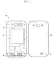
- FIG. 1 is a diagram illustrating a structure of an antenna 20 and a portable device 100 having the same according to an exemplary embodiment of the present invention.
- FIG. 2 is a diagram illustrating a portion of a battery cover of the portable device having different colors according to an exemplary embodiment of the present invention.
- FIG. 3 is a graph illustrating a resonant frequency of antennas employed within portable device housings of different colors.
- the portable device 100 includes a front case 10 in which a battery 12 is mounted and a battery cover 30 (also acting as a rear case of device 100) detached from the case 10 and for covering the battery 12.
- An antenna provided in the portable device includes an antenna radiator 20 housed in a portion of the case 10 and a resonant frequency compensation unit (dielectric tuner) 22 housed in the battery cover 30 facing the radiator 20.
- the radiator 20 may also be referred to herein as a radiator pattern 20, or as an antenna.
- the radiator 20 is disposed in a lower end portion of the case 10, beneath the battery 12, but is separated from the battery at a predetermined gap so that the battery 12 does not adversely influence the antenna performance (e.g., gain).
- the radiator 20 may be mounted in a fusion-bonding and in-mold type antenna structure on an upper surface of the case 10.
- Radiator 20 can also be mounted in the same or similar manner on the case 30.
- the dielectric tuner can still be mounted to the case 30, e.g., overlaid on top of the radiator 20. That is, the radiator 20 can be mounted directly on the case 30, and the dielectric tuner 20 can be mounted over the radiator 20, with a suitable attachment means such as a dielectric screw or glue securing it in place.
- the antenna radiator 20 may be designed as a radiator for constituting at least one antenna of a Bluetooth antenna (BT), global positioning system (GPS) antenna, WiFi antenna, a GSM mobile communications antenna, code division multiple access (CDMA), wideband code division multiple access (WCDMA), LTE antenna, and diversity antenna.
- BT Bluetooth antenna
- GPS global positioning system
- WiFi WiFi antenna
- GSM Global System for Mobile communications
- CDMA code division multiple access
- WCDMA wideband code division multiple access
- LTE antenna Long Term Evolution
- diversity antenna may be designed as a radiator for constituting at least one antenna of a Bluetooth antenna (BT), global positioning system (GPS) antenna, WiFi antenna, a GSM mobile communications antenna, code division multiple access (CDMA), wideband code division multiple access (WCDMA), LTE antenna, and diversity antenna.
- CDMA code division multiple access
- WCDMA wideband code division multiple access
- LTE long term evolution
- the radiator 20 may be configured for a single band antenna having a form of a monopole antenna in which a grounding stub is not connected or a single band antenna having a form of a PIFA antenna in which a grounding stub is connected at a periphery of a power supply line.
- an antenna size may be reduced compared to a monopole configuration, for operation at the same frequency band.
- the radiator 20 may be formed with silver (Ag) paste, copper (Cu) paste, or a synthetic substance thereof.
- the radiator 20 is electrically connected via a connection means (not shown) to a main printed circuit board (PCB) mounted to the case 10 to transfer a signal received from the outside to the main PCB.
- a connection means (not shown) to a main printed circuit board (PCB) mounted to the case 10 to transfer a signal received from the outside to the main PCB.
- PCB printed circuit board
- a phenomenon in which a dielectric constant of the case 30 adjacent the radiator 20 is changed according to a color or a material painted at the radiator occurs here, a change of a color or a material painted at the radiator is referred to as a change of an environment of a radiator.
- a graph of FIG. 3 represents resonant frequencies of three antennas produced with the same construction method and pattern, but painted with a red color, blue color, and white color. The graphs of FIG. 3 do not include the influence of the dielectric tuner 22.
- an intrinsic dielectric constant of the radiator 20 is changed according to a color or a material painted at a radiator and thus resonant frequencies of radiators are different.
- an antenna according to the present exemplary embodiment employs the resonant frequency compensation unit 22 at a location proximate the antenna, as shown in FIG. 1 .
- the radiator 20 is formed with a shared construction method and pattern of the antenna regardless of a color of a material painted near the radiator.
- the antenna employs the resonant frequency compensation unit (hereafter, "tuner") 22 having a predetermined dielectric constant that is pre-set based on a dielectric constant of a radiator changed by a color and a material painted near the radiator.
- the resonant frequency compensation unit hereafter, "tuner”
- the tuner 22 is disposed at a suitable distance to the radiator 20, to compensate for the change in dielectric constant caused by the painting of the case 30 and/or 10. In order words, the tuner 22 is disposed at a close distance that induces a change of the intrinsic dielectric constant of the radiator 20.
- the present exemplary embodiment illustrates an example in which the tuner 22 is disposed at an inner surface of the battery cover 30 facing the case 10 in which the radiator 20 is mounted, as shown in FIG. 2 .
- a mounting position of the tuner 22 is not limited thereto.
- the radiator 20 can alternatively be mounted to the battery cover 30 and the tuner 22 can be mounted directly over it to the battery cover 30, or the tuner 22 could be mounted to the case 10.
- a dielectric constant of the tuner 22 is pre-set to change the intrinsic dielectric constant of the radiator 20.
- the dielectric constant of the tuner 22 is set to adjust a resonant frequency of the radiator 20 to a preset resonant frequency.
- the preset resonant frequency may be set to a resonant frequency of one of, for example the red, blue, and white color cases. Therefore, a dielectric constant of the tuner 22 provided according to the red, blue, and white cases may be differently provided. Alternatively, the dimensions and/or exact location of the tuner 22 differ as a function of the case color to achieve the desired resonant frequency adjustment.
- the tuner 22 may provided in a form of a dielectric substance attached to one surface of the portable device, as shown in FIG. 2 .
- the tuner 22 When the tuner 22 is provided in a dielectric substance form attached to any surface of the portable device, the tuner 22 adjusts the intrinsic dielectric constant of the radiator 20 through a change of a parameter of at least one of an area, length, and width of the dielectric substance.
- a generally rectangular dielectric substance 32 may be provided in a polycarbonate (PC) sheet of a size of 5X10mm to correspond to the blue cover
- a dielectric substance 34 may be provided in a polycarbonate (PC) sheet of a size of 5X8mm to correspond to the red cover
- a dielectric substance 36 may be provided in a polycarbonate (PC) sheet of a size of 5X8mm to correspond to the white cover.
- the dielectric substances may be provided in other geometric shapes, e.g., discs or ellipses.
- a resonant frequency compensation unit may be provided by employing battery covers 31, 33, and 35 of a material having a predetermined dielectric constant, without utilizing a separate dielectric substance. In this way, a change of a dielectric constant of the covers 31, 33 and 35 produce a change in the intrinsic dielectric constant of the radiator 20, thereby adjusting the resonant frequency as desired to compensate for the dielectric constant change caused by the coloring of the covers.
- a material that the resonant frequency compensation unit may be made of can be at least one of acrylonitrile, butadiene, and styrene (ABS), polyamide (PA), polyacetal (POA), polycarbonate (PC), modified polyoxide (M-PRO), polybutylene terephthalate (PBT), polyimide (PI), polyphenylenesulfide (PPS), polyamide imide (PAI), polyetherimide (PEI), polyether ketone (PEK), liquid crystal polyester (LCP), syndiotactic polypropylene (SPS) or a synthetic substance thereof.
- ABS acrylonitrile, butadiene, and styrene
- PA polyamide
- POA polyacetal
- PC polycarbonate
- M-PRO modified polyoxide
- PBT polybutylene terephthalate
- PI polyimide
- PPS polyphenylenesulfide
- PAI polyamide imide
- PEI polyetherimide
- ABS that may constitute the resonant frequency compensation unit is a filler, and a characteristic thereof greatly changes according to a combination thereof, and has excellent mechanical characteristics, electrical characteristics, and chemical resistance. Because ABS may be plated, the ABS may be provided with metallic plastic.
- the materials have different intrinsic dielectric constants, and when the materials are disposed adjacent to the radiator 20, the intrinsic dielectric constant of the radiator 20 may be changed.
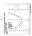
- FIG. 4 is a graph comparing resonant frequencies of a red color device's antenna according to an exemplary embodiment of the present invention, and a conventional device's antenna.
- FIG. 5 is a graph comparing resonant frequencies of an antenna within a white color portable device according to an exemplary embodiment of the present invention, and a conventional antenna.
- FIG. 6 is a table illustrating a total isotropic sensitivity (TIS)/total radiated power (TRP) measurement result of an antenna on a color basis according to an exemplary embodiment of the present invention.
- TIS total isotropic sensitivity
- TRP total radiated power
- a resonant frequency of a red color device's radiator is set to correspond to, for example a resonant frequency of a blue color device's radiator (i.e., a preset resonant frequency is set to a resonant frequency of a blue color device's radiator).
- a graph 'a' shown in FIG. 4 illustrates a graph of VSWR vs. frequency to illustrate a resonant frequency of a conventional red color device antenna
- a graph 'b' illustrates a resonant frequency of a blue color device 100 radiator
- a graph 'c' illustrates a resonant frequency of a red color device 100 radiator employing the resonant frequency compensation unit at a periphery thereof according to an exemplary embodiment of the present invention.
- a resonant frequency of the radiator 20 is changed to be almost the same as a resonant frequency of a blue color device's radiator 20. Meanwhile, the resonant frequency of the conventional device is shifted below a desired frequency, as the graph 'a' shows.
- a graph d shown in FIG. 5 illustrates a resonant frequency of a white device's antenna
- the graph b illustrates a resonant frequency of the blue device's radiator
- a graph e illustrates a resonant frequency of a white device's radiator employing the resonant frequency compensation unit 36 at a periphery thereof.
- a resonant frequency of the white device radiator is adjusted by the resonant frequency compensation unit 36 to be changed to approximately the same resonant frequency of the blue device radiator.
- TIS and TRP of the white device radiator are almost equally changed to TIS and TRP of the blue device radiator.
- TIS is defined as average power that can obtain from an ideal isotropic antenna and is a transmitting performance metric of an antenna.
- TRP is defined as the sum of entire power actually radiated by an antenna regardless of a direction or polarity and is a receiving performance metric of an antenna.
- TIS and TRP have a direct correlation to a dielectric constant of an antenna carrier it will be understood by those skilled in the art that a performance change of an antenna according to the present exemplary embodiment can be measured through TIS and TRP.
- FIG. 7 is a graph illustrating a resonant frequency of radiator units provided in a portable device employing a large capacity battery against a standard capacity battery.
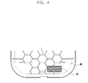
- FIG. 8 is a diagram illustrating an antenna according to an exemplary embodiment of the present invention and a portion of a portable device having the same.
- FIG. 9 is a graph comparing resonant frequencies of an antenna according to an exemplary embodiment of the present invention and a conventional antenna.
- antennas described in FIGS. 7 to 9 are produced with the same construction method and radiator pattern and are employed within portable devices having the same color.
- a resonant frequency of antennas in which sizes or capacities of a battery mounted at a periphery thereof are different is exemplified. Because a battery size is generally proportional to a battery capacity, graphs of a resonant frequency of an antenna are compared based on a battery capacity proportional to the battery size.
- FIG. 7 illustrates a graph f of an antenna at which a standard capacity battery is positioned at a periphery of an antenna and a graph g of an antenna in which a large capacity battery is positioned at a periphery of the antenna. It is seen from the graphs that the resonant frequency of the antenna changes due to the influence of the batteries.
- an antenna according to the present exemplary embodiment employs a resonant frequency compensation unit 42 at a periphery of the antenna, as shown in FIG. 8 .
- an antenna according to the present exemplary embodiment may be formed with the same antenna construction method and pattern regardless of a capacity or a size of a battery mounted at a periphery thereof.
- the antenna employs the resonant frequency compensation unit ("tuner") 42 having a predetermined dielectric constant that is set based on a dielectric constant of a radiator changed due to an influence of a capacity or a size of a battery mounted at a periphery thereof.
- the tuner 42 is changed according to the battery size.
- a configuration, function, and disposition position of the resonant frequency compensation unit 42 are similar or identical to those of the above-described resonant frequency compensation units and therefore a detailed description thereof is omitted.
- a preset resonant frequency may be set, for example to a resonant frequency of an antenna in which a battery of a standard capacity is mounted at a periphery thereof.
- the resonant frequency compensation unit 42 may be provided with a polycarbonate (PC) sheet of 5X10mm size to correspond to the standard capacity battery, and the dielectric substance 42 may be provided with a PC sheet of 17.5X17.5mm size to correspond to the large capacity battery.
- PC polycarbonate
- the dielectric substance 42 may be provided with a PC sheet of 17.5X17.5mm size to correspond to the large capacity battery.
- the resonant frequency compensation unit 42 by employing the resonant frequency compensation unit 42 at a periphery of an antenna in which a large capacity battery is mounted, it can be seen that a resonant frequency g of an antenna in which a large capacity battery is mounted at a periphery thereof becomes almost the same as a preset resonant frequency f. That is, it can be seen that a previous resonant frequency g of the antenna is changed to an adjusted resonant frequency h.
- the preset resonant frequency is a resonant frequency of an antenna in which a standard capacity of battery is mounted.
- an antenna and a portable device having the same can provide a structure that can simply compensate a resonant frequency change according to a change of a dielectric constant in a surrounding environment of the antenna.
- a changed resonant frequency of an antenna can be adjusted to a preset resonant frequency by employing the inventive tuner.
- a resonant frequency of the antenna can be adjusted with a simple source. Accordingly, it is unnecessary to separately produce a radiator pattern designated for different resonant frequencies due to different colors and materials and a capacity of a battery mounted at a periphery thereof.
- the resonant frequency can be adjusted to a preset resonant frequency.
- a common construction method and radiator pattern of the antenna can be utilized for the differing environments.
- a radiator pattern in a rear case, and by attaching an auxiliary dielectric substance to a battery cover or by employing a battery cover having a predetermined dielectric constant, mounting space of the antenna can be extended, and a thin portable device can be produced.
Landscapes
- Engineering & Computer Science (AREA)
- Computer Networks & Wireless Communication (AREA)
- Support Of Aerials (AREA)
- Details Of Aerials (AREA)
- Waveguide Aerials (AREA)
- Telephone Set Structure (AREA)
Applications Claiming Priority (1)
| Application Number | Priority Date | Filing Date | Title |
|---|---|---|---|
| KR1020120094974A KR20140028520A (ko) | 2012-08-29 | 2012-08-29 | 안테나 및 이를 구비하는 휴대단말장치 |
Publications (2)
| Publication Number | Publication Date |
|---|---|
| EP2704256A1 true EP2704256A1 (de) | 2014-03-05 |
| EP2704256B1 EP2704256B1 (de) | 2020-04-29 |
Family
ID=49036511
Family Applications (1)
| Application Number | Title | Priority Date | Filing Date |
|---|---|---|---|
| EP13182270.2A Active EP2704256B1 (de) | 2012-08-29 | 2013-08-29 | Antenne und tragbare Vorrichtung damit |
Country Status (4)
| Country | Link |
|---|---|
| US (1) | US9300049B2 (de) |
| EP (1) | EP2704256B1 (de) |
| KR (1) | KR20140028520A (de) |
| CN (1) | CN103682643B (de) |
Cited By (1)
| Publication number | Priority date | Publication date | Assignee | Title |
|---|---|---|---|---|
| CN112151954A (zh) * | 2019-06-26 | 2020-12-29 | Oppo广东移动通信有限公司 | 壳体组件、电子设备及壳体组件的介电常数调节方法 |
Families Citing this family (4)
| Publication number | Priority date | Publication date | Assignee | Title |
|---|---|---|---|---|
| US9634709B2 (en) | 2014-09-04 | 2017-04-25 | Apple Inc. | Removable electronic device case with supplemental antenna element |
| US9654164B2 (en) * | 2015-04-14 | 2017-05-16 | Apple Inc. | Removable electronic device case with supplemental wireless circuitry |
| CN106876898B (zh) * | 2017-03-01 | 2019-11-29 | 北京小米移动软件有限公司 | 终端 |
| KR102654617B1 (ko) * | 2018-08-07 | 2024-04-04 | 삼성전자주식회사 | 전자 장치 외부의 매질에 따라 공진 주파수를 조정하여 위성 신호를 수신하는 방법 및 이를 지원하는 전자 장치 |
Citations (5)
| Publication number | Priority date | Publication date | Assignee | Title |
|---|---|---|---|---|
| EP1870956A1 (de) * | 2006-06-23 | 2007-12-26 | LG Electronics Inc. | Mobiles Endgerät mit einer internen Antenne mit leitender Schicht |
| EP2192652A1 (de) * | 2008-11-28 | 2010-06-02 | Lg Electronics Inc. | Mobiles Endgerät umfassend ein mit einer Antenne gekoppeltes leitendes Bauteil |
| US20100234081A1 (en) * | 2009-03-13 | 2010-09-16 | Wong Alfred Y | Rf radiation redirection away from portable communication device user |
| US20100302123A1 (en) * | 2009-05-29 | 2010-12-02 | Infineon Technologies Ag | Wireless Communication Device Antenna With Tuning Elements |
| EP2381530A2 (de) * | 2010-04-22 | 2011-10-26 | Samsung Electro-Mechanics Co., Ltd. | Antennenstrukturrahmen, Gehäuse für elektronische Vorrichtung mit Antennenstrukturrahmen und elektronische Vorrichtung mit Gehäuse für elektronische Vorrichtung |
Family Cites Families (9)
| Publication number | Priority date | Publication date | Assignee | Title |
|---|---|---|---|---|
| US5320561A (en) * | 1992-06-19 | 1994-06-14 | Motorola, Inc. | Connector for providing programming, testing, and power signals |
| JP2005102286A (ja) | 2004-11-08 | 2005-04-14 | Toshiba Corp | 電子機器 |
| JP2007180704A (ja) | 2005-12-27 | 2007-07-12 | Fujikura Ltd | アンテナ素子とその製造方法 |
| US8150484B2 (en) * | 2007-09-11 | 2012-04-03 | Nokia Corporation | Protective housings for wireless transmission apparatus and associated methods |
| JP2009103458A (ja) * | 2007-10-19 | 2009-05-14 | Denso Corp | レーダ出力最適化方法、およびレーダ出力最適化装置 |
| US8169373B2 (en) * | 2008-09-05 | 2012-05-01 | Apple Inc. | Antennas with tuning structure for handheld devices |
| US8766858B2 (en) | 2010-08-27 | 2014-07-01 | Apple Inc. | Antennas mounted under dielectric plates |
| KR101155510B1 (ko) | 2010-09-14 | 2012-06-18 | 한국과학기술원 | 위상 배열 안테나의 삽입 위상 지연 보상을 위한 레이돔-안테나 조립체 및 이를 이용한 삽입 위상 지연 보상 방법 |
| KR20120056699A (ko) | 2010-11-25 | 2012-06-04 | 엘지이노텍 주식회사 | 커버에 안테나가 내장된 휴대용 장치 |
-
2012
- 2012-08-29 KR KR1020120094974A patent/KR20140028520A/ko not_active Ceased
-
2013
- 2013-08-28 US US14/012,197 patent/US9300049B2/en active Active
- 2013-08-29 CN CN201310384998.5A patent/CN103682643B/zh active Active
- 2013-08-29 EP EP13182270.2A patent/EP2704256B1/de active Active
Patent Citations (5)
| Publication number | Priority date | Publication date | Assignee | Title |
|---|---|---|---|---|
| EP1870956A1 (de) * | 2006-06-23 | 2007-12-26 | LG Electronics Inc. | Mobiles Endgerät mit einer internen Antenne mit leitender Schicht |
| EP2192652A1 (de) * | 2008-11-28 | 2010-06-02 | Lg Electronics Inc. | Mobiles Endgerät umfassend ein mit einer Antenne gekoppeltes leitendes Bauteil |
| US20100234081A1 (en) * | 2009-03-13 | 2010-09-16 | Wong Alfred Y | Rf radiation redirection away from portable communication device user |
| US20100302123A1 (en) * | 2009-05-29 | 2010-12-02 | Infineon Technologies Ag | Wireless Communication Device Antenna With Tuning Elements |
| EP2381530A2 (de) * | 2010-04-22 | 2011-10-26 | Samsung Electro-Mechanics Co., Ltd. | Antennenstrukturrahmen, Gehäuse für elektronische Vorrichtung mit Antennenstrukturrahmen und elektronische Vorrichtung mit Gehäuse für elektronische Vorrichtung |
Cited By (2)
| Publication number | Priority date | Publication date | Assignee | Title |
|---|---|---|---|---|
| CN112151954A (zh) * | 2019-06-26 | 2020-12-29 | Oppo广东移动通信有限公司 | 壳体组件、电子设备及壳体组件的介电常数调节方法 |
| CN112151954B (zh) * | 2019-06-26 | 2023-07-28 | Oppo广东移动通信有限公司 | 壳体组件、电子设备及壳体组件的介电常数调节方法 |
Also Published As
| Publication number | Publication date |
|---|---|
| CN103682643B (zh) | 2018-10-12 |
| US20140062816A1 (en) | 2014-03-06 |
| CN103682643A (zh) | 2014-03-26 |
| EP2704256B1 (de) | 2020-04-29 |
| US9300049B2 (en) | 2016-03-29 |
| KR20140028520A (ko) | 2014-03-10 |
Similar Documents
| Publication | Publication Date | Title |
|---|---|---|
| US10446915B2 (en) | Mobile device | |
| CN102709684B (zh) | 具有包绕的基底的多元件天线结构 | |
| US9099790B2 (en) | Mobile device and antenna structure therein | |
| US7768462B2 (en) | Multiband antenna for handheld electronic devices | |
| EP2664073B1 (de) | Elektronische Vorrichtung mit einem leitfähigen Rahmen, das einen Teil eines Antennenresonanzelements bildet | |
| EP2629368B1 (de) | Mobile Vorrichtung | |
| US10490902B2 (en) | Mobile device | |
| KR20150042180A (ko) | 힌지결합된 인클로저를 구비한 전자 장치의 안테나 구조체 | |
| US9300049B2 (en) | Antenna and portable device having the same | |
| CN210780900U (zh) | 终端设备 | |
| US20150171508A1 (en) | Antenna device, and communication device with antenna device | |
| US11088439B2 (en) | Mobile device and detachable antenna structure | |
| KR20140148006A (ko) | 안테나 장치 및 그것을 갖는 전자 장치 | |
| US20220131267A1 (en) | Antenna structure | |
| CN111697317A (zh) | 移动装置 | |
| US9601825B1 (en) | Mobile device | |
| US9331379B2 (en) | Mobile device and manufacturing method thereof | |
| US20250062534A1 (en) | Communication device | |
| EP2824764B1 (de) | Antennenvorrichtung und elektronische Vorrichtung mit der Antennenvorrichtung | |
| US20240145918A1 (en) | Antenna structure | |
| CN112311910A (zh) | 移动装置 | |
| KR101305283B1 (ko) | 안테나 장치를 구비하는 휴대 단말기 | |
| EP2182644B1 (de) | Antennenvorrichtung für ein tragbares drahtloses Endgerät | |
| US20240178569A1 (en) | Mobile device supporting wideband operation | |
| KR101838700B1 (ko) | 근접을 감지하는 장치 및 이를 구비하는 휴대용 단말기 |
Legal Events
| Date | Code | Title | Description |
|---|---|---|---|
| AK | Designated contracting states |
Kind code of ref document: A1 Designated state(s): AL AT BE BG CH CY CZ DE DK EE ES FI FR GB GR HR HU IE IS IT LI LT LU LV MC MK MT NL NO PL PT RO RS SE SI SK SM TR |
|
| AX | Request for extension of the european patent |
Extension state: BA ME |
|
| PUAI | Public reference made under article 153(3) epc to a published international application that has entered the european phase |
Free format text: ORIGINAL CODE: 0009012 |
|
| 17P | Request for examination filed |
Effective date: 20141014 |
|
| 17Q | First examination report despatched |
Effective date: 20160817 |
|
| STAA | Information on the status of an ep patent application or granted ep patent |
Free format text: STATUS: EXAMINATION IS IN PROGRESS |
|
| GRAP | Despatch of communication of intention to grant a patent |
Free format text: ORIGINAL CODE: EPIDOSNIGR1 |
|
| STAA | Information on the status of an ep patent application or granted ep patent |
Free format text: STATUS: GRANT OF PATENT IS INTENDED |
|
| INTG | Intention to grant announced |
Effective date: 20200127 |
|
| GRAS | Grant fee paid |
Free format text: ORIGINAL CODE: EPIDOSNIGR3 |
|
| GRAA | (expected) grant |
Free format text: ORIGINAL CODE: 0009210 |
|
| STAA | Information on the status of an ep patent application or granted ep patent |
Free format text: STATUS: THE PATENT HAS BEEN GRANTED |
|
| AK | Designated contracting states |
Kind code of ref document: B1 Designated state(s): AL AT BE BG CH CY CZ DE DK EE ES FI FR GB GR HR HU IE IS IT LI LT LU LV MC MK MT NL NO PL PT RO RS SE SI SK SM TR |
|
| REG | Reference to a national code |
Ref country code: GB Ref legal event code: FG4D |
|
| REG | Reference to a national code |
Ref country code: CH Ref legal event code: EP |
|
| REG | Reference to a national code |
Ref country code: DE Ref legal event code: R096 Ref document number: 602013068375 Country of ref document: DE |
|
| REG | Reference to a national code |
Ref country code: AT Ref legal event code: REF Ref document number: 1264686 Country of ref document: AT Kind code of ref document: T Effective date: 20200515 |
|
| REG | Reference to a national code |
Ref country code: IE Ref legal event code: FG4D |
|
| REG | Reference to a national code |
Ref country code: NL Ref legal event code: MP Effective date: 20200429 |
|
| REG | Reference to a national code |
Ref country code: LT Ref legal event code: MG4D |
|
| PG25 | Lapsed in a contracting state [announced via postgrant information from national office to epo] |
Ref country code: SE Free format text: LAPSE BECAUSE OF FAILURE TO SUBMIT A TRANSLATION OF THE DESCRIPTION OR TO PAY THE FEE WITHIN THE PRESCRIBED TIME-LIMIT Effective date: 20200429 Ref country code: IS Free format text: LAPSE BECAUSE OF FAILURE TO SUBMIT A TRANSLATION OF THE DESCRIPTION OR TO PAY THE FEE WITHIN THE PRESCRIBED TIME-LIMIT Effective date: 20200829 Ref country code: PT Free format text: LAPSE BECAUSE OF FAILURE TO SUBMIT A TRANSLATION OF THE DESCRIPTION OR TO PAY THE FEE WITHIN THE PRESCRIBED TIME-LIMIT Effective date: 20200831 Ref country code: LT Free format text: LAPSE BECAUSE OF FAILURE TO SUBMIT A TRANSLATION OF THE DESCRIPTION OR TO PAY THE FEE WITHIN THE PRESCRIBED TIME-LIMIT Effective date: 20200429 Ref country code: NO Free format text: LAPSE BECAUSE OF FAILURE TO SUBMIT A TRANSLATION OF THE DESCRIPTION OR TO PAY THE FEE WITHIN THE PRESCRIBED TIME-LIMIT Effective date: 20200729 Ref country code: FI Free format text: LAPSE BECAUSE OF FAILURE TO SUBMIT A TRANSLATION OF THE DESCRIPTION OR TO PAY THE FEE WITHIN THE PRESCRIBED TIME-LIMIT Effective date: 20200429 Ref country code: GR Free format text: LAPSE BECAUSE OF FAILURE TO SUBMIT A TRANSLATION OF THE DESCRIPTION OR TO PAY THE FEE WITHIN THE PRESCRIBED TIME-LIMIT Effective date: 20200730 |
|
| REG | Reference to a national code |
Ref country code: AT Ref legal event code: MK05 Ref document number: 1264686 Country of ref document: AT Kind code of ref document: T Effective date: 20200429 |
|
| PG25 | Lapsed in a contracting state [announced via postgrant information from national office to epo] |
Ref country code: HR Free format text: LAPSE BECAUSE OF FAILURE TO SUBMIT A TRANSLATION OF THE DESCRIPTION OR TO PAY THE FEE WITHIN THE PRESCRIBED TIME-LIMIT Effective date: 20200429 Ref country code: LV Free format text: LAPSE BECAUSE OF FAILURE TO SUBMIT A TRANSLATION OF THE DESCRIPTION OR TO PAY THE FEE WITHIN THE PRESCRIBED TIME-LIMIT Effective date: 20200429 Ref country code: RS Free format text: LAPSE BECAUSE OF FAILURE TO SUBMIT A TRANSLATION OF THE DESCRIPTION OR TO PAY THE FEE WITHIN THE PRESCRIBED TIME-LIMIT Effective date: 20200429 Ref country code: BG Free format text: LAPSE BECAUSE OF FAILURE TO SUBMIT A TRANSLATION OF THE DESCRIPTION OR TO PAY THE FEE WITHIN THE PRESCRIBED TIME-LIMIT Effective date: 20200729 |
|
| PGFP | Annual fee paid to national office [announced via postgrant information from national office to epo] |
Ref country code: IT Payment date: 20200814 Year of fee payment: 8 |
|
| PG25 | Lapsed in a contracting state [announced via postgrant information from national office to epo] |
Ref country code: AL Free format text: LAPSE BECAUSE OF FAILURE TO SUBMIT A TRANSLATION OF THE DESCRIPTION OR TO PAY THE FEE WITHIN THE PRESCRIBED TIME-LIMIT Effective date: 20200429 Ref country code: NL Free format text: LAPSE BECAUSE OF FAILURE TO SUBMIT A TRANSLATION OF THE DESCRIPTION OR TO PAY THE FEE WITHIN THE PRESCRIBED TIME-LIMIT Effective date: 20200429 |
|
| PG25 | Lapsed in a contracting state [announced via postgrant information from national office to epo] |
Ref country code: DK Free format text: LAPSE BECAUSE OF FAILURE TO SUBMIT A TRANSLATION OF THE DESCRIPTION OR TO PAY THE FEE WITHIN THE PRESCRIBED TIME-LIMIT Effective date: 20200429 Ref country code: ES Free format text: LAPSE BECAUSE OF FAILURE TO SUBMIT A TRANSLATION OF THE DESCRIPTION OR TO PAY THE FEE WITHIN THE PRESCRIBED TIME-LIMIT Effective date: 20200429 Ref country code: RO Free format text: LAPSE BECAUSE OF FAILURE TO SUBMIT A TRANSLATION OF THE DESCRIPTION OR TO PAY THE FEE WITHIN THE PRESCRIBED TIME-LIMIT Effective date: 20200429 Ref country code: EE Free format text: LAPSE BECAUSE OF FAILURE TO SUBMIT A TRANSLATION OF THE DESCRIPTION OR TO PAY THE FEE WITHIN THE PRESCRIBED TIME-LIMIT Effective date: 20200429 Ref country code: AT Free format text: LAPSE BECAUSE OF FAILURE TO SUBMIT A TRANSLATION OF THE DESCRIPTION OR TO PAY THE FEE WITHIN THE PRESCRIBED TIME-LIMIT Effective date: 20200429 Ref country code: CZ Free format text: LAPSE BECAUSE OF FAILURE TO SUBMIT A TRANSLATION OF THE DESCRIPTION OR TO PAY THE FEE WITHIN THE PRESCRIBED TIME-LIMIT Effective date: 20200429 Ref country code: SM Free format text: LAPSE BECAUSE OF FAILURE TO SUBMIT A TRANSLATION OF THE DESCRIPTION OR TO PAY THE FEE WITHIN THE PRESCRIBED TIME-LIMIT Effective date: 20200429 |
|
| REG | Reference to a national code |
Ref country code: DE Ref legal event code: R097 Ref document number: 602013068375 Country of ref document: DE |
|
| PG25 | Lapsed in a contracting state [announced via postgrant information from national office to epo] |
Ref country code: SK Free format text: LAPSE BECAUSE OF FAILURE TO SUBMIT A TRANSLATION OF THE DESCRIPTION OR TO PAY THE FEE WITHIN THE PRESCRIBED TIME-LIMIT Effective date: 20200429 Ref country code: PL Free format text: LAPSE BECAUSE OF FAILURE TO SUBMIT A TRANSLATION OF THE DESCRIPTION OR TO PAY THE FEE WITHIN THE PRESCRIBED TIME-LIMIT Effective date: 20200429 |
|
| PLBE | No opposition filed within time limit |
Free format text: ORIGINAL CODE: 0009261 |
|
| STAA | Information on the status of an ep patent application or granted ep patent |
Free format text: STATUS: NO OPPOSITION FILED WITHIN TIME LIMIT |
|
| PG25 | Lapsed in a contracting state [announced via postgrant information from national office to epo] |
Ref country code: MC Free format text: LAPSE BECAUSE OF FAILURE TO SUBMIT A TRANSLATION OF THE DESCRIPTION OR TO PAY THE FEE WITHIN THE PRESCRIBED TIME-LIMIT Effective date: 20200429 |
|
| REG | Reference to a national code |
Ref country code: CH Ref legal event code: PL |
|
| 26N | No opposition filed |
Effective date: 20210201 |
|
| GBPC | Gb: european patent ceased through non-payment of renewal fee |
Effective date: 20200829 |
|
| PG25 | Lapsed in a contracting state [announced via postgrant information from national office to epo] |
Ref country code: LI Free format text: LAPSE BECAUSE OF NON-PAYMENT OF DUE FEES Effective date: 20200831 Ref country code: CH Free format text: LAPSE BECAUSE OF NON-PAYMENT OF DUE FEES Effective date: 20200831 Ref country code: LU Free format text: LAPSE BECAUSE OF NON-PAYMENT OF DUE FEES Effective date: 20200829 |
|
| REG | Reference to a national code |
Ref country code: BE Ref legal event code: MM Effective date: 20200831 |
|
| PG25 | Lapsed in a contracting state [announced via postgrant information from national office to epo] |
Ref country code: SI Free format text: LAPSE BECAUSE OF FAILURE TO SUBMIT A TRANSLATION OF THE DESCRIPTION OR TO PAY THE FEE WITHIN THE PRESCRIBED TIME-LIMIT Effective date: 20200429 |
|
| PG25 | Lapsed in a contracting state [announced via postgrant information from national office to epo] |
Ref country code: FR Free format text: LAPSE BECAUSE OF NON-PAYMENT OF DUE FEES Effective date: 20200831 |
|
| PG25 | Lapsed in a contracting state [announced via postgrant information from national office to epo] |
Ref country code: IE Free format text: LAPSE BECAUSE OF NON-PAYMENT OF DUE FEES Effective date: 20200829 Ref country code: GB Free format text: LAPSE BECAUSE OF NON-PAYMENT OF DUE FEES Effective date: 20200829 Ref country code: BE Free format text: LAPSE BECAUSE OF NON-PAYMENT OF DUE FEES Effective date: 20200831 |
|
| PG25 | Lapsed in a contracting state [announced via postgrant information from national office to epo] |
Ref country code: TR Free format text: LAPSE BECAUSE OF FAILURE TO SUBMIT A TRANSLATION OF THE DESCRIPTION OR TO PAY THE FEE WITHIN THE PRESCRIBED TIME-LIMIT Effective date: 20200429 Ref country code: MT Free format text: LAPSE BECAUSE OF FAILURE TO SUBMIT A TRANSLATION OF THE DESCRIPTION OR TO PAY THE FEE WITHIN THE PRESCRIBED TIME-LIMIT Effective date: 20200429 Ref country code: CY Free format text: LAPSE BECAUSE OF FAILURE TO SUBMIT A TRANSLATION OF THE DESCRIPTION OR TO PAY THE FEE WITHIN THE PRESCRIBED TIME-LIMIT Effective date: 20200429 |
|
| PG25 | Lapsed in a contracting state [announced via postgrant information from national office to epo] |
Ref country code: MK Free format text: LAPSE BECAUSE OF FAILURE TO SUBMIT A TRANSLATION OF THE DESCRIPTION OR TO PAY THE FEE WITHIN THE PRESCRIBED TIME-LIMIT Effective date: 20200429 |
|
| PG25 | Lapsed in a contracting state [announced via postgrant information from national office to epo] |
Ref country code: IT Free format text: LAPSE BECAUSE OF NON-PAYMENT OF DUE FEES Effective date: 20210829 |
|
| PGFP | Annual fee paid to national office [announced via postgrant information from national office to epo] |
Ref country code: DE Payment date: 20250721 Year of fee payment: 13 |