EP2704302A1 - Commutation d'un convertisseur CC-CC - Google Patents
Commutation d'un convertisseur CC-CC Download PDFInfo
- Publication number
- EP2704302A1 EP2704302A1 EP12182917.0A EP12182917A EP2704302A1 EP 2704302 A1 EP2704302 A1 EP 2704302A1 EP 12182917 A EP12182917 A EP 12182917A EP 2704302 A1 EP2704302 A1 EP 2704302A1
- Authority
- EP
- European Patent Office
- Prior art keywords
- switching
- converter
- pulses
- state
- fulfilled
- Prior art date
- Legal status (The legal status is an assumption and is not a legal conclusion. Google has not performed a legal analysis and makes no representation as to the accuracy of the status listed.)
- Granted
Links
Images

Classifications
-
- B—PERFORMING OPERATIONS; TRANSPORTING
- B60—VEHICLES IN GENERAL
- B60L—PROPULSION OF ELECTRICALLY-PROPELLED VEHICLES; SUPPLYING ELECTRIC POWER FOR AUXILIARY EQUIPMENT OF ELECTRICALLY-PROPELLED VEHICLES; ELECTRODYNAMIC BRAKE SYSTEMS FOR VEHICLES IN GENERAL; MAGNETIC SUSPENSION OR LEVITATION FOR VEHICLES; MONITORING OPERATING VARIABLES OF ELECTRICALLY-PROPELLED VEHICLES; ELECTRIC SAFETY DEVICES FOR ELECTRICALLY-PROPELLED VEHICLES
- B60L3/00—Electric devices on electrically-propelled vehicles for safety purposes; Monitoring operating variables, e.g. speed, deceleration or energy consumption
- B60L3/0023—Detecting, eliminating, remedying or compensating for drive train abnormalities, e.g. failures within the drive train
- B60L3/003—Detecting, eliminating, remedying or compensating for drive train abnormalities, e.g. failures within the drive train relating to inverters
-
- H—ELECTRICITY
- H02—GENERATION; CONVERSION OR DISTRIBUTION OF ELECTRIC POWER
- H02M—APPARATUS FOR CONVERSION BETWEEN AC AND AC, BETWEEN AC AND DC, OR BETWEEN DC AND DC, AND FOR USE WITH MAINS OR SIMILAR POWER SUPPLY SYSTEMS; CONVERSION OF DC OR AC INPUT POWER INTO SURGE OUTPUT POWER; CONTROL OR REGULATION THEREOF
- H02M3/00—Conversion of DC power input into DC power output
- H02M3/22—Conversion of DC power input into DC power output with intermediate conversion into AC
- H02M3/24—Conversion of DC power input into DC power output with intermediate conversion into AC by static converters
- H02M3/28—Conversion of DC power input into DC power output with intermediate conversion into AC by static converters using discharge tubes with control electrode or semiconductor devices with control electrode to produce the intermediate AC
- H02M3/325—Conversion of DC power input into DC power output with intermediate conversion into AC by static converters using discharge tubes with control electrode or semiconductor devices with control electrode to produce the intermediate AC using devices of a triode or a transistor type requiring continuous application of a control signal
- H02M3/335—Conversion of DC power input into DC power output with intermediate conversion into AC by static converters using discharge tubes with control electrode or semiconductor devices with control electrode to produce the intermediate AC using devices of a triode or a transistor type requiring continuous application of a control signal using semiconductor devices only
- H02M3/33569—Conversion of DC power input into DC power output with intermediate conversion into AC by static converters using discharge tubes with control electrode or semiconductor devices with control electrode to produce the intermediate AC using devices of a triode or a transistor type requiring continuous application of a control signal using semiconductor devices only having several active switching elements
- H02M3/33576—Conversion of DC power input into DC power output with intermediate conversion into AC by static converters using discharge tubes with control electrode or semiconductor devices with control electrode to produce the intermediate AC using devices of a triode or a transistor type requiring continuous application of a control signal using semiconductor devices only having several active switching elements having at least one active switching element at the secondary side of an isolation transformer
- H02M3/33584—Bidirectional converters
-
- B—PERFORMING OPERATIONS; TRANSPORTING
- B60—VEHICLES IN GENERAL
- B60L—PROPULSION OF ELECTRICALLY-PROPELLED VEHICLES; SUPPLYING ELECTRIC POWER FOR AUXILIARY EQUIPMENT OF ELECTRICALLY-PROPELLED VEHICLES; ELECTRODYNAMIC BRAKE SYSTEMS FOR VEHICLES IN GENERAL; MAGNETIC SUSPENSION OR LEVITATION FOR VEHICLES; MONITORING OPERATING VARIABLES OF ELECTRICALLY-PROPELLED VEHICLES; ELECTRIC SAFETY DEVICES FOR ELECTRICALLY-PROPELLED VEHICLES
- B60L15/00—Methods, circuits, or devices for controlling the traction-motor speed of electrically-propelled vehicles
- B60L15/002—Methods, circuits, or devices for controlling the traction-motor speed of electrically-propelled vehicles for control of propulsion for monorail vehicles, suspension vehicles or rack railways; for control of magnetic suspension or levitation for vehicles for propulsion purposes
-
- B—PERFORMING OPERATIONS; TRANSPORTING
- B60—VEHICLES IN GENERAL
- B60L—PROPULSION OF ELECTRICALLY-PROPELLED VEHICLES; SUPPLYING ELECTRIC POWER FOR AUXILIARY EQUIPMENT OF ELECTRICALLY-PROPELLED VEHICLES; ELECTRODYNAMIC BRAKE SYSTEMS FOR VEHICLES IN GENERAL; MAGNETIC SUSPENSION OR LEVITATION FOR VEHICLES; MONITORING OPERATING VARIABLES OF ELECTRICALLY-PROPELLED VEHICLES; ELECTRIC SAFETY DEVICES FOR ELECTRICALLY-PROPELLED VEHICLES
- B60L9/00—Electric propulsion with power supply external to the vehicle
- B60L9/02—Electric propulsion with power supply external to the vehicle using DC motors
- B60L9/08—Electric propulsion with power supply external to the vehicle using DC motors fed from AC supply lines
- B60L9/12—Electric propulsion with power supply external to the vehicle using DC motors fed from AC supply lines with static converters
-
- B—PERFORMING OPERATIONS; TRANSPORTING
- B60—VEHICLES IN GENERAL
- B60L—PROPULSION OF ELECTRICALLY-PROPELLED VEHICLES; SUPPLYING ELECTRIC POWER FOR AUXILIARY EQUIPMENT OF ELECTRICALLY-PROPELLED VEHICLES; ELECTRODYNAMIC BRAKE SYSTEMS FOR VEHICLES IN GENERAL; MAGNETIC SUSPENSION OR LEVITATION FOR VEHICLES; MONITORING OPERATING VARIABLES OF ELECTRICALLY-PROPELLED VEHICLES; ELECTRIC SAFETY DEVICES FOR ELECTRICALLY-PROPELLED VEHICLES
- B60L2200/00—Type of vehicles
- B60L2200/26—Rail vehicles
-
- B—PERFORMING OPERATIONS; TRANSPORTING
- B60—VEHICLES IN GENERAL
- B60L—PROPULSION OF ELECTRICALLY-PROPELLED VEHICLES; SUPPLYING ELECTRIC POWER FOR AUXILIARY EQUIPMENT OF ELECTRICALLY-PROPELLED VEHICLES; ELECTRODYNAMIC BRAKE SYSTEMS FOR VEHICLES IN GENERAL; MAGNETIC SUSPENSION OR LEVITATION FOR VEHICLES; MONITORING OPERATING VARIABLES OF ELECTRICALLY-PROPELLED VEHICLES; ELECTRIC SAFETY DEVICES FOR ELECTRICALLY-PROPELLED VEHICLES
- B60L2210/00—Converter types
- B60L2210/30—AC to DC converters
-
- B—PERFORMING OPERATIONS; TRANSPORTING
- B60—VEHICLES IN GENERAL
- B60L—PROPULSION OF ELECTRICALLY-PROPELLED VEHICLES; SUPPLYING ELECTRIC POWER FOR AUXILIARY EQUIPMENT OF ELECTRICALLY-PROPELLED VEHICLES; ELECTRODYNAMIC BRAKE SYSTEMS FOR VEHICLES IN GENERAL; MAGNETIC SUSPENSION OR LEVITATION FOR VEHICLES; MONITORING OPERATING VARIABLES OF ELECTRICALLY-PROPELLED VEHICLES; ELECTRIC SAFETY DEVICES FOR ELECTRICALLY-PROPELLED VEHICLES
- B60L2210/00—Converter types
- B60L2210/40—DC to AC converters
- B60L2210/42—Voltage source inverters
-
- B—PERFORMING OPERATIONS; TRANSPORTING
- B60—VEHICLES IN GENERAL
- B60L—PROPULSION OF ELECTRICALLY-PROPELLED VEHICLES; SUPPLYING ELECTRIC POWER FOR AUXILIARY EQUIPMENT OF ELECTRICALLY-PROPELLED VEHICLES; ELECTRODYNAMIC BRAKE SYSTEMS FOR VEHICLES IN GENERAL; MAGNETIC SUSPENSION OR LEVITATION FOR VEHICLES; MONITORING OPERATING VARIABLES OF ELECTRICALLY-PROPELLED VEHICLES; ELECTRIC SAFETY DEVICES FOR ELECTRICALLY-PROPELLED VEHICLES
- B60L2240/00—Control parameters of input or output; Target parameters
- B60L2240/40—Drive Train control parameters
- B60L2240/52—Drive Train control parameters related to converters
- B60L2240/526—Operating parameters
-
- B—PERFORMING OPERATIONS; TRANSPORTING
- B60—VEHICLES IN GENERAL
- B60L—PROPULSION OF ELECTRICALLY-PROPELLED VEHICLES; SUPPLYING ELECTRIC POWER FOR AUXILIARY EQUIPMENT OF ELECTRICALLY-PROPELLED VEHICLES; ELECTRODYNAMIC BRAKE SYSTEMS FOR VEHICLES IN GENERAL; MAGNETIC SUSPENSION OR LEVITATION FOR VEHICLES; MONITORING OPERATING VARIABLES OF ELECTRICALLY-PROPELLED VEHICLES; ELECTRIC SAFETY DEVICES FOR ELECTRICALLY-PROPELLED VEHICLES
- B60L2240/00—Control parameters of input or output; Target parameters
- B60L2240/40—Drive Train control parameters
- B60L2240/52—Drive Train control parameters related to converters
- B60L2240/527—Voltage
-
- Y—GENERAL TAGGING OF NEW TECHNOLOGICAL DEVELOPMENTS; GENERAL TAGGING OF CROSS-SECTIONAL TECHNOLOGIES SPANNING OVER SEVERAL SECTIONS OF THE IPC; TECHNICAL SUBJECTS COVERED BY FORMER USPC CROSS-REFERENCE ART COLLECTIONS [XRACs] AND DIGESTS
- Y02—TECHNOLOGIES OR APPLICATIONS FOR MITIGATION OR ADAPTATION AGAINST CLIMATE CHANGE
- Y02T—CLIMATE CHANGE MITIGATION TECHNOLOGIES RELATED TO TRANSPORTATION
- Y02T10/00—Road transport of goods or passengers
- Y02T10/60—Other road transportation technologies with climate change mitigation effect
- Y02T10/64—Electric machine technologies in electromobility
-
- Y—GENERAL TAGGING OF NEW TECHNOLOGICAL DEVELOPMENTS; GENERAL TAGGING OF CROSS-SECTIONAL TECHNOLOGIES SPANNING OVER SEVERAL SECTIONS OF THE IPC; TECHNICAL SUBJECTS COVERED BY FORMER USPC CROSS-REFERENCE ART COLLECTIONS [XRACs] AND DIGESTS
- Y02—TECHNOLOGIES OR APPLICATIONS FOR MITIGATION OR ADAPTATION AGAINST CLIMATE CHANGE
- Y02T—CLIMATE CHANGE MITIGATION TECHNOLOGIES RELATED TO TRANSPORTATION
- Y02T10/00—Road transport of goods or passengers
- Y02T10/60—Other road transportation technologies with climate change mitigation effect
- Y02T10/72—Electric energy management in electromobility
Definitions
- the invention relates to a method for controlling a DC-to-DC converter, a controller of a DC-to-DC converter and a modular converter.
- Electrical trains or trams may have a modular converter that comprises a plurality of converter cells that produce from an AC input voltage a DC output voltage that is supplied to other electrical installations on-board, for example to one or more electrical motors.
- the AC input voltage is supplied from an overhead line.
- the converter cells of the modular converter may comprise a resonant DC-to-DC converter, in which a DC-to-AC converter on the line side is connected via a resonant transformer with an AC-to-DC converter on the motor side.
- Both the DC-to-AC converter and the AC-to-DC converter may be active converters with controllable semiconductor switches.
- the semiconductor switches of the DC-to-DC converter may be switched with a fixed switching frequency and 50 % duty cycle.
- either the semiconductor switches of the primary line side or the secondary motor side of the DC-to-DC converter are switched.
- This may provide zero voltage switching (ZVS) during turn-on of the semiconductor switches, and low current switching during turn-off.
- ZVS zero voltage switching
- this switching strategy may result in low switching losses and thus in a high-efficiency DC-to-DC conversion at nominal power ratings.
- An aspect of the invention relates to a method for controlling a DC-to-DC converter.
- the DC-to-DC converter may be part of a converter cell of a modular converter, which may be used for supplying electrical motors of a train with power.
- the DC-to-DC converter comprises a DC-to-AC (sub)converter and an AC-to-DC (sub)converter connected in series with a transformer and a capacitor, both the DC-to-AC converter and the AC-to-DC converter comprising semiconductor switches.
- the DC-to-DC converter may be a resonant converter with the transformer being part of the resonant tank.
- the method comprises the steps of: determining (or measuring) a DC input voltage and a DC output voltage of the DC-to-DC-converter; determining whether a switching condition based on the DC input voltage and the DC output voltage is fulfilled; and generating a switching signal with switching pulses for switching the semiconductor switches of at least one of the DC-to-AC converter and the AC-to-DC converter, wherein the generation of switching pulses is blocked, when the switching condition is not fulfilled.
- the switching signal may comprise a two level switching signal for each semiconductor switch to be switched.
- the semiconductor switch When the signal is off, the semiconductor switch is also off. Conversely, when the signal is on, the semiconductor switch is also on.
- a switching pulse may be a part of the switching signal in which the switching signal is on.
- the voltages may be measured and a switching condition that receives the two voltages as input values may be evaluated. When the condition is fulfilled, a switching signal with switching pulses may be produced. When the condition is not fulfilled, a switching signal which is off may be produced.
- the first side of the DC-to-DC converter may be an input side or line side.
- the second side of the DC-to-DC converter may be an output side or motor side.
- the switching condition may be based on the load on the DC-to-DC converter, which may directly or indirectly contribute to the switching condition.
- the DC-to-DC converter may be energy-efficiently switched under light-load or no-load conditions.
- the number and shape of switching pulses sent to the DC-to-DC converter may be adapted based on the DC voltages on both sides of the DC-to-DC converter, and optionally on the DC-to-DC converter current.
- an energy-efficient switching strategy at varying power ratings and not only at a nominal operating point may be implemented in a modular converter.
- the control method ensures a stable operation of the DC-to-DC converter, i.e. deviations of the DC voltages from their reference values may be counteracted, such that in a steady-state operation, the ratio between both DC voltages is maintained.
- the control method may work bi-directional, i.e. may support a power flow from the first side to the second side, and vice versa.
- the control method may reflect the modular design of the modular converter by avoiding communication between the converter cells, and may adjust themselves to a varying number of converter cells (such that availability of the converter arrangement is sustained if one cell is failing).
- the switching signal comprises regular switching pulses starting regularly with respect to a time period of the switching signal.
- the regular switching pulses may have a length of half of the switching period.
- the switching pulses may start at 0 % of the time period and end at 50 % of the time period, or start at 50 % of the time period and end at 100 % of the time period.
- the switching signal comprises reduced switching pulses that are shorter than the regular switching pulses.
- the reduced switching pulses may have half of the length of the regular switching pulses.
- the reduced switching pulses may start at 25 % of the time period and end at 50 % of the time period, or start at 75 % of the time period and end at 100 % of the time period.
- a reduced switching pulse is generated, when passing from a blocked switching signal to an unblocked switching signal.
- a sequence or train of switching pulses may begin with a reduced switching pulse, which may or may not be followed by at least one regular switching pulse. It may be possible that all sequences of switching pulses start with a reduced switching pulse.
- the switching signal comprises switching pulses for switching an upper semiconductor switch of one of the subconverters and switching pulses for switching a lower semiconductor switch of the subconverter.
- the switching pulses of the two semiconductor switches are alternating with each other, i.e. the upper semiconductor switch is switched on, when the lower semiconductor switch is switched off, and vice versa.
- the number of reduced switching pulses for the upper semiconductor switch may equal the number of reduced switching pulses for the lower semiconductor switch and/or the number of full switching pulses for the upper semiconductor switch may equal the number of full switching pulses for the lower semiconductor switch. In such a way, the load on the two semiconductor switches may be balanced.
- the switching condition is based on the difference of the DC input voltage and the DC output voltage.
- the switching control method supports the balancing of the DC voltages on the first and the second side of the DC-to-DC converter.
- a current through the DC-to-DC converter for example a DC output current is determined or measured.
- the switching condition may be based on the current and/or the transferred power calculated from the current.
- the transferred power may be based on the product of a DC voltage and the corresponding current.
- a control method for switching pulse generation of a sequence of full and reduced switching pulses for the DC-to-DC converter may be implemented.
- the generation of the switching pulses may be based on the first and second DC voltages and optionally on the power transferred by the modular converter.
- the method further comprises the steps of: generating an unfiltered switching signal (for example with a pulse generator); and forming the switching signal applied to the semiconductors switches by blocking the unfiltered switching signal, when the switching condition is not fulfilled (for example by filtering with a pulse filter).
- a pulse generator may produce a regular, unfiltered switching signal, which is filtered by a pulse filter that blocks the switching pulses, when the switching condition is not fulfilled.
- the method further comprises the steps of: blocking the unfiltered switching signal with a state machine having at least one unblocking state in which the unfiltered signal is not blocked, and at least one blocking state in which the unfiltered signal is blocked; and transitioning the state machine from an unblocking state to a blocking state, when the switching condition is not fulfilled, and transitioning the state machine from a blocking state to an unblocking state, when the switching condition is fulfilled.
- the pulse filter may comprise an internal state machine, which has state transitions that are based on the fulfillment of the switching transition.
- the method further comprises the steps of: transitioning the state machine from a first unblocking state to a first blocking state, when the switching condition is not fulfilled at the middle of a time period of the unfiltered switching signal; transitioning the state machine from the first blocking state to a second unblocking state, when the switching condition is fulfilled at three quarters of the time period; transitioning the state machine from the second unblocking state to a second blocking state, when the switching condition is not fulfilled at the end of the time period; and transitioning the state machine from the second blocking state to the first unblocking state, when the switching condition is fulfilled at one quarter of the time period.
- the state machine may comprise four states which alternately block and unblock the unfiltered switching signal in such a way, that alternately reduced switching pulses are generated for the upper and the lower semiconductor switch of one subconverter of the DC-to-DC converter.
- a further aspect of the invention relates to a controller of a DC-to-DC converter, wherein the controller is adapted for performing the method as described in the above and in the following.
- the controller may be a local controller or control unit associated with a converter cell of the modular converter, or may be a main controller for the modular converter, which is adapted for controlling more than one or all converter cells of the modular converter.
- the controller comprises a pulse generator for generating an unfiltered switching signal; and a pulse filter for blocking the unfiltered switching signal, when the switching condition is not fulfilled.
- the pulse generator may generate an unfiltered switching signal with intermittent pulses, for example with a normal PWM pattern.
- the unfiltered switching signal may be used during normal mode (normal load) operation of the modular converter.
- the pulse filter may omit or pass on the switching pulses of the unfiltered signal based on the measured or estimated values of the first and second DC voltage and optionally on the transferred power.
- a further aspect of the invention relates to a modular converter for supplying at least one electrical motor with a DC output voltage.
- the electrical motor may be the motor of a train or a tram. It has to be understood that features of the method as described in the above and in the following may be features of the modular converter and the controller as described in the above and in the following, and vice versa.
- the converter comprises a plurality of converter cells, which are connected in series on a first side and which are connected in parallel on a second side.
- the first side of a converter cell may be an input side or line side.
- the second side of the converter cell may be an output side or motor side.
- Each converter cell may comprise an AC-to-DC converter for converting a first side AC voltage into a first side DC voltage, and a DC-to-DC converter for converting the first side DC voltage into a second side DC voltage.
- the converter further comprises a controller as described in the above and in the following for controlling at least one of the DC-to-DC converters of the converter cells.
- the AC-to-DC converter may be a full-bridge or half-bridge converter, which is adapted for converting a first side AC voltage into a first side DC voltage, or vice versa.
- the DC-to-DC converter may be a resonant converter, which is adapted for converting the first DC voltage into a second DC voltage, or vice versa.
- the controller or control unit may generate and provide switching signals to the AC-to-DC converter and to the DC-to-DC converter.
- the modular converter comprises local controllers, each local controller associated with a converter cell and adapted for controlling the DC-to-DC converter of the converter cell.
- the control method may be implemented separately for each converter cell on a local cell controller.
- the control method may generate the switching signal for the DC-to-DC converter of a single converter cell.
- the modular converter comprises a main controller, which is adapted for controlling at least two DC-to-DC converters of the converter cells.
- the control method may be implemented for several converter cells on a main controller or central controller.
- the control method may generate the switching signal of the DC-to-DC converters of a plurality of converter cells.
- a subset of the converter cells of the modular converter may be controlled by using the control method, as described in the above and in the following, and a subset of the converter cells may be controlled in a different form.
- Fig. 1 shows a converter 10 for an electric train or tram.
- the converter has an input 12 that is connected via an pantograph 14 with a catenary or overhead line 16, which supplies the converter 10 with an medium-voltage AC input voltage.
- the converter 10 has an earthing point 18, which connects the converter 10 via the wheels 20 of the train or tram to the earth 22.
- the converter 10 has a positive DC output 24 and a negative DC output 25, which supplies a load 26 of the train or tram with a DC output voltage of about 1 kV.
- the load 26 may comprise an electric DC motor, another converters and/or an auxiliary power supply.
- the converter 10 is an AC-to-DC converter with an AC side 32 providing the input 12 and the earthing point 18, and a DC side 34 providing the output phases 24, 25.
- the converter 10 has a modular structure and comprises a plurality of (for example nine) four-terminal converter cells 36.
- the converter cells 36 are connected in series on the AC side 32, i.e. connected in series between the input 12 and the earthing point 18 and in parallel on the DC side 34, i.e. connected in parallel to the two outputs 24, 25.
- Each converter cell 36 comprises a short-circuit switch 38, an AC-to-DC converter 40 and a DC-to-DC converter 42.
- the short-circuit switches 38 of a converter cell 36 is connected in series with the short-circuit switches 38 of the other converter cells 36 and comprises two power semiconductor switches 44 connected in series in opposite directions.
- the short-circuit switches 38 may comprise other kind of switches, for example, an electromechanical switch.
- the AC-to-DC converter 40 is an active front end with four power semiconductor switches 46 connected into an H-bridge.
- the AC-to-DC converter 40 and the DC-to-DC converter 42 are connected via a DC link, which comprises a capacitance 50.
- the output of the DC-to-DC converter 42 of a converter cell 36 is connected in parallel with the outputs of the DC-to-DC converters 42 of the other converter cells 36.
- the DC-to-DC converter 42 is a resonant converter and comprises a first side resonant (sub)converter 52, a resonant tank or transformer 54, and a second side resonant (sub)converter 56, which are connected in series.
- the first side resonant converter 52 is connected to the DC link 50 and comprises an upper and a lower power semiconductor switch 58 connected in series.
- One input of the primary side of the transformer 54 is connected between the two power semiconductor switches 58.
- the other input of the primary side of the transformer 54 is connected via a capacitor 60 to the negative side of the DC-link 50.
- the second side resonant converter 56 comprises an upper and a lower power semiconductor switch 62 connected in series, which are connected in parallel with a second DC link with two capacitors 64connected in series.
- One input of the secondary side of the transformer 54 is connected between the two power semiconductor switches 62.
- the other input of the primary side of the transformer 54 is connected between the capacitors 64.
- Alternative connections are also possible.
- All the power semiconductor switches 44, 46, 58, 62 may be IGBTs.
- Each converter cell 36 comprises a local controller 70, which is adapted to control the switches 44, 46, 58, 62 of the respective converter cell 36.
- the local controllers 70 are communicatively interconnected with a main controller 72, which is adapted to control the local controller 70.
- Fig. 2 schematically shows a converter cell 36 together with a controller 70, 72. It has to be noted that the switching method as explained in the above and in the following and shown in Fig 4 may be performed by a local controller 70 or by the main controller 72.
- the first side AC voltage 80 is converted by an appropriate switching of the AC-to-DC converter 40 to a first DC voltage 82.
- This first DC voltage 82 is converted by the DC-to-DC converter 42 to a second DC voltage 84.
- Fig. 3 shows a flow diagram for a method for controlling a converter as shown in Fig. 2 .
- the first DC voltage 82 is measured on the first or line side and input to the controller 70, 72.
- the second DC voltage 84 and the second DC current 86 are measured on the second or motor side, and input to the controller 70, 72.
- the second DC current 86 can be either positive or negative.
- the controller 70, 72 comprises a pulse generator 90, which is adapted to generate pulse width modulated switching signals 92, 94.
- the pulse generator 90 generates the pulse width modulated switching signals 92, 94 based on the second DC current 86. For example, the pulse generator 90 generates switching pulses with a constant switching frequency and a 50 % duty cycle.
- the output switching signal 92 of the pulse generator 90 is used for controlling the upper and lower power semiconductor switch 58 of the first side resonant converter 52 connected to the first, line side DC link 50.
- the output switching signal 94 of the pulse generator 90 is used for controlling the upper and lower power semiconductor switch 62 of the second side resonant converter 56 connected to the second, motor side DC link 64, 66.
- the pulse generator 90 may generate intermittent pulses 92 for the upper and lower semiconductor 58 of the first side of the DC-to-DC converter 42 and may keep the semiconductors 62 of the second side of the DC-to-DC converter 42 switched off by generating appropriate pulses 9, or vice versa.
- the controller 70, 72 comprises a pulse filter 96, which receives and filters the switching signals 92, 94 from the pulse generator 90.
- step 114 based on the measured first and second DC voltages 82, 84 and optionally based on the measured second DC current 86, the number of switching pulses may be reduced by the pulse filter 96.
- the pulse filter 96 decides repeatedly between one of the options of (1) passing through pulses of the switching signal 92, 94 and (2) omitting pulses of the switching signal 92, 94.
- the decision is also based on the energy flow of the controller 10, e.g. by taking into account the second side DC current 86.
- the pulse filter 96 By omitting and filtering pulses, the pulse filter 96 generates a filtered switching signal 98 from the switching signal 92, which is used for controlling the upper and lower power semiconductor switch 58, and a filtered switching signal 100 from the switching signal 94, which is used for controlling the upper and lower power semiconductor switch 62.
- Fig. 4 shows a state machine 120 that may be part of the pulse filter 96.
- the state machine 120 comprises four modes, S1, S2, S3, and S4.
- the switching signals 92, 94 are passed through the pulse filter 96.
- the passing through is indicated by a "+".
- the switching signals 92, 94 are blocked and switching pulses may be omitted from the switching signals 92, 94.
- the blocking is indicated by a "-".
- the switching signals 92, 94 are blocked, the respective power semiconductor switches 58, 62 are switched off, such that no switching losses occur.
- the decision to move from one mode to the next mode is based on the time T in the switching period, and on a switching condition C.
- the condition C may be a function of the measured signals: first side DC voltage U DC1 , 82, second side DC voltage U DC2 , 84 and optionally the current I DC2 , 86 flowing through the converter 10.
- An example for such a switching condition C may be that the difference (or the absolute value of the difference) between the first side and the second side DC voltages U DC1 - U DC2 is bigger than a predefined threshold.
- condition C may be k 1 ⁇ U DC ⁇ 1 - U DC ⁇ 2 + k 2 ⁇ I DC ⁇ 2 ⁇ U DC ⁇ 2 ⁇ k 2 wherein k 1 , k 2 , and k 3 are suitable constants.
- the first term on the left hand side of condition C depends on the difference of the first and second DC voltages 82, 84.
- the second term depends on the power flow through the DC-to-DC converter 42.
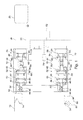
- the state machine 120 will be explained also with respect to Fig. 5 , which shows an example of possible switching signals based on the omitting or reducing of switching pulses.
- the upper dashed and solid lines represent the switching signal 92, 94, 98, 100 for the upper semiconductor 58, 62
- the lower dashed and solid lines represent the switching signal 92, 94, 98, 100 for the lower semiconductors 58, 62.
- the dashed lines indicate the switching signal 92 for the upper and lower semiconductors 58, or the switching signal 94 for the upper and lower semiconductors 62.
- the solid lines indicate the switching signal 98 for the upper and lower semiconductors 58, or the switching signal 100 for the upper and lower semiconductors 62.
- the pulse generator 90 generates switching pulses with a constant switching frequency with a period T and a 50 % duty cycle.
- half pulses 144 appear alternatively at the upper and the lower semiconductor switching signal 98, 100. Due the usage of half pulses 144, the adaption of the current oscillations to the resonant cycle of the resonant converter 42 is faster and the losses are lower.
- the number of half pulses 144 for the lower semiconductors is equal to the number of half pulses 144 for the upper semiconductors, and the same amount of energy is transferred by the upper and lower semiconductor switches.
- the half pulses 144 either initiate a pulse train (a sequence of switching pulses) or they may appear in the middle of a pulse train. Depending on the input to the pulse filter 96, it is also possible that a half pulse 144 is followed by a single switching pulse or by a pulse break (in which the signals 92, 94 are blocked).
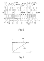
- Fig. 6 shows a schematic comparison of the switching losses 150 of the converter 10 without the use of the pulse filter 96, and the switching losses 152 when using the pulse filter 96. While the switching losses 150 are nearly constant for the 50 % duty cycle operation, filtering the switching pulses enables switching losses 152 which are nearly proportional to the transmitted power P. Therefore, it is possible to keep the efficiency of the DC-to-DC converter 42 high under light-load and no-load conditions, in contrast to the 50 % duty cycle scheme.
- the control method converges to the normal PWM pulse pattern (50 % duty cycle) operation for normal-load operation. No switching between different control strategies is needed. (Under normal conditions, the pulse filter 96 will stay persistently in mode S1 or S3.)
- the DC-to-DC converter 42 of each converter cell 36 of the modular converter 10 may be controlled independently of the others, no inter-level communication needed.
- the first side DC voltage 82 may be measured for safety reasons.
- the DC-to-DC converters 42 may have to be ramped up the stationary operation. After the stationary operation is reached, the control method allows instantaneous start and stop of the switching pulses, no ramping needed.
- the control method may be seen as a continuous adaptation of the switching strategy for different power levels.
Landscapes
- Engineering & Computer Science (AREA)
- Power Engineering (AREA)
- Transportation (AREA)
- Mechanical Engineering (AREA)
- Life Sciences & Earth Sciences (AREA)
- Sustainable Development (AREA)
- Sustainable Energy (AREA)
- Dc-Dc Converters (AREA)
Priority Applications (3)
| Application Number | Priority Date | Filing Date | Title |
|---|---|---|---|
| EP12182917.0A EP2704302B1 (fr) | 2012-09-04 | 2012-09-04 | Commutation d'un convertisseur CC-CC |
| CN201380046117.7A CN104584406B (zh) | 2012-09-04 | 2013-09-04 | 开关dc‑dc转换器 |
| PCT/EP2013/068289 WO2014037403A2 (fr) | 2012-09-04 | 2013-09-04 | Commutation d'un convertisseur cc-cc |
Applications Claiming Priority (1)
| Application Number | Priority Date | Filing Date | Title |
|---|---|---|---|
| EP12182917.0A EP2704302B1 (fr) | 2012-09-04 | 2012-09-04 | Commutation d'un convertisseur CC-CC |
Publications (2)
| Publication Number | Publication Date |
|---|---|
| EP2704302A1 true EP2704302A1 (fr) | 2014-03-05 |
| EP2704302B1 EP2704302B1 (fr) | 2019-06-05 |
Family
ID=46799129
Family Applications (1)
| Application Number | Title | Priority Date | Filing Date |
|---|---|---|---|
| EP12182917.0A Active EP2704302B1 (fr) | 2012-09-04 | 2012-09-04 | Commutation d'un convertisseur CC-CC |
Country Status (3)
| Country | Link |
|---|---|
| EP (1) | EP2704302B1 (fr) |
| CN (1) | CN104584406B (fr) |
| WO (1) | WO2014037403A2 (fr) |
Cited By (1)
| Publication number | Priority date | Publication date | Assignee | Title |
|---|---|---|---|---|
| EP3051680A1 (fr) * | 2015-01-30 | 2016-08-03 | ABB Technology AG | Procédé de protection d'un convertisseur modulaire par comparaison entre une valeur estimée avec un observateur et une valeur mesurée du courant d'entrée |
Families Citing this family (1)
| Publication number | Priority date | Publication date | Assignee | Title |
|---|---|---|---|---|
| EP3410590A1 (fr) * | 2017-06-02 | 2018-12-05 | General Electric Technology GmbH | Perfectionnements apportés ou se rapportant à des convertisseurs destinés à interconnecter un premier et un second réseau électrique |
Citations (4)
| Publication number | Priority date | Publication date | Assignee | Title |
|---|---|---|---|---|
| EP0820893A2 (fr) * | 1996-07-26 | 1998-01-28 | ABB Daimler-Benz Transportation (Technology) GmbH | Système de traction pour véhicule sur rails et procédé de commande correspondant |
| US20050254273A1 (en) * | 2004-03-30 | 2005-11-17 | Christophe Soudier | Method, apparatus and article for bi-directional DC/DC power conversion |
| JP2011024294A (ja) * | 2009-07-14 | 2011-02-03 | Daihen Corp | 電力変換回路の制御回路、および、この制御回路を備えた電力変換装置 |
| US20120161717A1 (en) * | 2009-03-12 | 2012-06-28 | Guo Xing Li | Circuits and methos for battery charging |
Family Cites Families (2)
| Publication number | Priority date | Publication date | Assignee | Title |
|---|---|---|---|---|
| US7952895B2 (en) * | 2008-05-29 | 2011-05-31 | Power Integrations, Inc. | Method and apparatus for implementing an unregulated dormant mode in a power converter |
| DE102010044322A1 (de) * | 2010-09-03 | 2012-03-08 | Bombardier Transportation Gmbh | Elektrische Energieversorgungsanordnung für Antriebseinrichtungen von Schienenfahrzeugen |
-
2012
- 2012-09-04 EP EP12182917.0A patent/EP2704302B1/fr active Active
-
2013
- 2013-09-04 CN CN201380046117.7A patent/CN104584406B/zh active Active
- 2013-09-04 WO PCT/EP2013/068289 patent/WO2014037403A2/fr not_active Ceased
Patent Citations (4)
| Publication number | Priority date | Publication date | Assignee | Title |
|---|---|---|---|---|
| EP0820893A2 (fr) * | 1996-07-26 | 1998-01-28 | ABB Daimler-Benz Transportation (Technology) GmbH | Système de traction pour véhicule sur rails et procédé de commande correspondant |
| US20050254273A1 (en) * | 2004-03-30 | 2005-11-17 | Christophe Soudier | Method, apparatus and article for bi-directional DC/DC power conversion |
| US20120161717A1 (en) * | 2009-03-12 | 2012-06-28 | Guo Xing Li | Circuits and methos for battery charging |
| JP2011024294A (ja) * | 2009-07-14 | 2011-02-03 | Daihen Corp | 電力変換回路の制御回路、および、この制御回路を備えた電力変換装置 |
Non-Patent Citations (2)
| Title |
|---|
| HONGLIN ZHOU ET AL: "Modeling and Control for a Bidirectional Buck Boost Cascade Inverter", IEEE TRANSACTIONS ON POWER ELECTRONICS, IEEE SERVICE CENTER, PISCATAWAY, NJ, US, vol. 27, no. 3, 1 March 2012 (2012-03-01), pages 1401 - 1413, XP011406672, ISSN: 0885-8993, DOI: 10.1109/TPEL.2010.2103957 * |
| ZAHRA MALEKJAMSHIDI ET AL: "Comparative analysis of ANN and SSM controllers in a ZVCS-Full Bridge Series-Parallel Resonant DC-DC converter", POWER ELECTRONICS AND DRIVE SYSTEMS (PEDS), 2011 IEEE NINTH INTERNATIONAL CONFERENCE ON, IEEE, 5 December 2011 (2011-12-05), pages 643 - 647, XP032112424, ISBN: 978-1-61284-999-7, DOI: 10.1109/PEDS.2011.6147319 * |
Cited By (1)
| Publication number | Priority date | Publication date | Assignee | Title |
|---|---|---|---|---|
| EP3051680A1 (fr) * | 2015-01-30 | 2016-08-03 | ABB Technology AG | Procédé de protection d'un convertisseur modulaire par comparaison entre une valeur estimée avec un observateur et une valeur mesurée du courant d'entrée |
Also Published As
| Publication number | Publication date |
|---|---|
| CN104584406B (zh) | 2018-03-02 |
| EP2704302B1 (fr) | 2019-06-05 |
| CN104584406A (zh) | 2015-04-29 |
| WO2014037403A2 (fr) | 2014-03-13 |
| WO2014037403A3 (fr) | 2014-06-19 |
Similar Documents
| Publication | Publication Date | Title |
|---|---|---|
| EP2892752B1 (fr) | Commande d'un convertisseur modulaire | |
| EP2995495B1 (fr) | Procédé de commande d'un convertisseur modulaire | |
| JP6736370B2 (ja) | 電力変換システム | |
| US8508961B2 (en) | Power conversion apparatus | |
| US10434882B2 (en) | Track-bound vehicle converter | |
| TWI538351B (zh) | 不斷電電源裝置 | |
| US20150015181A1 (en) | Dc/dc converter | |
| JP5681785B2 (ja) | 電力変換装置 | |
| US9698684B2 (en) | Adaptive soft switching control for power converter | |
| JP6736369B2 (ja) | 電力変換システム | |
| WO2014056742A2 (fr) | Commande de convertisseur modulaire | |
| US9270192B2 (en) | Variable speed drive provided with a supercapacitor module | |
| KR101393235B1 (ko) | 고장 감내형 pwm 스위칭에 의한 전력변환장치 및 그 제어방법 | |
| CN114421789A (zh) | 牵引辅助变流器的预充电装置、系统及方法 | |
| JP6786268B2 (ja) | 蓄電システム | |
| JP2017189053A (ja) | 電動機装置 | |
| EP2704302B1 (fr) | Commutation d'un convertisseur CC-CC | |
| CN104956564B (zh) | 变流器和运行变流器的方法 | |
| CN105024537B (zh) | 启动再生式转换器的方法和再生式转换器 | |
| JP6815762B2 (ja) | 電力変換システム | |
| JP2015204665A (ja) | 電力変換装置及びそれを備えた鉄道車両 | |
| JP2013106393A (ja) | 瞬低補償装置 | |
| JP5929537B2 (ja) | インバータの共通電源装置 | |
| JP2010252437A (ja) | キャパシタの充放電制御装置およびキャパシタの充放電制御装置の制御方法 |
Legal Events
| Date | Code | Title | Description |
|---|---|---|---|
| AK | Designated contracting states |
Kind code of ref document: A1 Designated state(s): AL AT BE BG CH CY CZ DE DK EE ES FI FR GB GR HR HU IE IS IT LI LT LU LV MC MK MT NL NO PL PT RO RS SE SI SK SM TR |
|
| AX | Request for extension of the european patent |
Extension state: BA ME |
|
| PUAI | Public reference made under article 153(3) epc to a published international application that has entered the european phase |
Free format text: ORIGINAL CODE: 0009012 |
|
| 17P | Request for examination filed |
Effective date: 20140905 |
|
| RBV | Designated contracting states (corrected) |
Designated state(s): AL AT BE BG CH CY CZ DE DK EE ES FI FR GB GR HR HU IE IS IT LI LT LU LV MC MK MT NL NO PL PT RO RS SE SI SK SM TR |
|
| RAP1 | Party data changed (applicant data changed or rights of an application transferred) |
Owner name: ABB SCHWEIZ AG |
|
| STAA | Information on the status of an ep patent application or granted ep patent |
Free format text: STATUS: EXAMINATION IS IN PROGRESS |
|
| 17Q | First examination report despatched |
Effective date: 20170907 |
|
| GRAP | Despatch of communication of intention to grant a patent |
Free format text: ORIGINAL CODE: EPIDOSNIGR1 |
|
| STAA | Information on the status of an ep patent application or granted ep patent |
Free format text: STATUS: GRANT OF PATENT IS INTENDED |
|
| INTG | Intention to grant announced |
Effective date: 20181221 |
|
| GRAS | Grant fee paid |
Free format text: ORIGINAL CODE: EPIDOSNIGR3 |
|
| GRAA | (expected) grant |
Free format text: ORIGINAL CODE: 0009210 |
|
| STAA | Information on the status of an ep patent application or granted ep patent |
Free format text: STATUS: THE PATENT HAS BEEN GRANTED |
|
| AK | Designated contracting states |
Kind code of ref document: B1 Designated state(s): AL AT BE BG CH CY CZ DE DK EE ES FI FR GB GR HR HU IE IS IT LI LT LU LV MC MK MT NL NO PL PT RO RS SE SI SK SM TR |
|
| REG | Reference to a national code |
Ref country code: GB Ref legal event code: FG4D |
|
| REG | Reference to a national code |
Ref country code: CH Ref legal event code: EP |
|
| REG | Reference to a national code |
Ref country code: AT Ref legal event code: REF Ref document number: 1140995 Country of ref document: AT Kind code of ref document: T Effective date: 20190615 |
|
| REG | Reference to a national code |
Ref country code: IE Ref legal event code: FG4D |
|
| REG | Reference to a national code |
Ref country code: DE Ref legal event code: R096 Ref document number: 602012060670 Country of ref document: DE |
|
| REG | Reference to a national code |
Ref country code: NL Ref legal event code: MP Effective date: 20190605 |
|
| REG | Reference to a national code |
Ref country code: LT Ref legal event code: MG4D |
|
| PG25 | Lapsed in a contracting state [announced via postgrant information from national office to epo] |
Ref country code: SE Free format text: LAPSE BECAUSE OF FAILURE TO SUBMIT A TRANSLATION OF THE DESCRIPTION OR TO PAY THE FEE WITHIN THE PRESCRIBED TIME-LIMIT Effective date: 20190605 Ref country code: ES Free format text: LAPSE BECAUSE OF FAILURE TO SUBMIT A TRANSLATION OF THE DESCRIPTION OR TO PAY THE FEE WITHIN THE PRESCRIBED TIME-LIMIT Effective date: 20190605 Ref country code: LT Free format text: LAPSE BECAUSE OF FAILURE TO SUBMIT A TRANSLATION OF THE DESCRIPTION OR TO PAY THE FEE WITHIN THE PRESCRIBED TIME-LIMIT Effective date: 20190605 Ref country code: AL Free format text: LAPSE BECAUSE OF FAILURE TO SUBMIT A TRANSLATION OF THE DESCRIPTION OR TO PAY THE FEE WITHIN THE PRESCRIBED TIME-LIMIT Effective date: 20190605 Ref country code: FI Free format text: LAPSE BECAUSE OF FAILURE TO SUBMIT A TRANSLATION OF THE DESCRIPTION OR TO PAY THE FEE WITHIN THE PRESCRIBED TIME-LIMIT Effective date: 20190605 Ref country code: NO Free format text: LAPSE BECAUSE OF FAILURE TO SUBMIT A TRANSLATION OF THE DESCRIPTION OR TO PAY THE FEE WITHIN THE PRESCRIBED TIME-LIMIT Effective date: 20190905 Ref country code: HR Free format text: LAPSE BECAUSE OF FAILURE TO SUBMIT A TRANSLATION OF THE DESCRIPTION OR TO PAY THE FEE WITHIN THE PRESCRIBED TIME-LIMIT Effective date: 20190605 |
|
| PG25 | Lapsed in a contracting state [announced via postgrant information from national office to epo] |
Ref country code: BG Free format text: LAPSE BECAUSE OF FAILURE TO SUBMIT A TRANSLATION OF THE DESCRIPTION OR TO PAY THE FEE WITHIN THE PRESCRIBED TIME-LIMIT Effective date: 20190905 Ref country code: GR Free format text: LAPSE BECAUSE OF FAILURE TO SUBMIT A TRANSLATION OF THE DESCRIPTION OR TO PAY THE FEE WITHIN THE PRESCRIBED TIME-LIMIT Effective date: 20190906 Ref country code: RS Free format text: LAPSE BECAUSE OF FAILURE TO SUBMIT A TRANSLATION OF THE DESCRIPTION OR TO PAY THE FEE WITHIN THE PRESCRIBED TIME-LIMIT Effective date: 20190605 Ref country code: LV Free format text: LAPSE BECAUSE OF FAILURE TO SUBMIT A TRANSLATION OF THE DESCRIPTION OR TO PAY THE FEE WITHIN THE PRESCRIBED TIME-LIMIT Effective date: 20190605 |
|
| REG | Reference to a national code |
Ref country code: AT Ref legal event code: MK05 Ref document number: 1140995 Country of ref document: AT Kind code of ref document: T Effective date: 20190605 |
|
| PG25 | Lapsed in a contracting state [announced via postgrant information from national office to epo] |
Ref country code: NL Free format text: LAPSE BECAUSE OF FAILURE TO SUBMIT A TRANSLATION OF THE DESCRIPTION OR TO PAY THE FEE WITHIN THE PRESCRIBED TIME-LIMIT Effective date: 20190605 Ref country code: AT Free format text: LAPSE BECAUSE OF FAILURE TO SUBMIT A TRANSLATION OF THE DESCRIPTION OR TO PAY THE FEE WITHIN THE PRESCRIBED TIME-LIMIT Effective date: 20190605 Ref country code: EE Free format text: LAPSE BECAUSE OF FAILURE TO SUBMIT A TRANSLATION OF THE DESCRIPTION OR TO PAY THE FEE WITHIN THE PRESCRIBED TIME-LIMIT Effective date: 20190605 Ref country code: RO Free format text: LAPSE BECAUSE OF FAILURE TO SUBMIT A TRANSLATION OF THE DESCRIPTION OR TO PAY THE FEE WITHIN THE PRESCRIBED TIME-LIMIT Effective date: 20190605 Ref country code: CZ Free format text: LAPSE BECAUSE OF FAILURE TO SUBMIT A TRANSLATION OF THE DESCRIPTION OR TO PAY THE FEE WITHIN THE PRESCRIBED TIME-LIMIT Effective date: 20190605 Ref country code: PT Free format text: LAPSE BECAUSE OF FAILURE TO SUBMIT A TRANSLATION OF THE DESCRIPTION OR TO PAY THE FEE WITHIN THE PRESCRIBED TIME-LIMIT Effective date: 20191007 Ref country code: SK Free format text: LAPSE BECAUSE OF FAILURE TO SUBMIT A TRANSLATION OF THE DESCRIPTION OR TO PAY THE FEE WITHIN THE PRESCRIBED TIME-LIMIT Effective date: 20190605 |
|
| PG25 | Lapsed in a contracting state [announced via postgrant information from national office to epo] |
Ref country code: SM Free format text: LAPSE BECAUSE OF FAILURE TO SUBMIT A TRANSLATION OF THE DESCRIPTION OR TO PAY THE FEE WITHIN THE PRESCRIBED TIME-LIMIT Effective date: 20190605 Ref country code: IS Free format text: LAPSE BECAUSE OF FAILURE TO SUBMIT A TRANSLATION OF THE DESCRIPTION OR TO PAY THE FEE WITHIN THE PRESCRIBED TIME-LIMIT Effective date: 20191005 Ref country code: IT Free format text: LAPSE BECAUSE OF FAILURE TO SUBMIT A TRANSLATION OF THE DESCRIPTION OR TO PAY THE FEE WITHIN THE PRESCRIBED TIME-LIMIT Effective date: 20190605 |
|
| REG | Reference to a national code |
Ref country code: DE Ref legal event code: R097 Ref document number: 602012060670 Country of ref document: DE |
|
| PG25 | Lapsed in a contracting state [announced via postgrant information from national office to epo] |
Ref country code: TR Free format text: LAPSE BECAUSE OF FAILURE TO SUBMIT A TRANSLATION OF THE DESCRIPTION OR TO PAY THE FEE WITHIN THE PRESCRIBED TIME-LIMIT Effective date: 20190605 |
|
| PLBE | No opposition filed within time limit |
Free format text: ORIGINAL CODE: 0009261 |
|
| STAA | Information on the status of an ep patent application or granted ep patent |
Free format text: STATUS: NO OPPOSITION FILED WITHIN TIME LIMIT |
|
| PG25 | Lapsed in a contracting state [announced via postgrant information from national office to epo] |
Ref country code: DK Free format text: LAPSE BECAUSE OF FAILURE TO SUBMIT A TRANSLATION OF THE DESCRIPTION OR TO PAY THE FEE WITHIN THE PRESCRIBED TIME-LIMIT Effective date: 20190605 Ref country code: PL Free format text: LAPSE BECAUSE OF FAILURE TO SUBMIT A TRANSLATION OF THE DESCRIPTION OR TO PAY THE FEE WITHIN THE PRESCRIBED TIME-LIMIT Effective date: 20190605 |
|
| 26N | No opposition filed |
Effective date: 20200306 |
|
| PG25 | Lapsed in a contracting state [announced via postgrant information from national office to epo] |
Ref country code: MC Free format text: LAPSE BECAUSE OF FAILURE TO SUBMIT A TRANSLATION OF THE DESCRIPTION OR TO PAY THE FEE WITHIN THE PRESCRIBED TIME-LIMIT Effective date: 20190605 Ref country code: SI Free format text: LAPSE BECAUSE OF FAILURE TO SUBMIT A TRANSLATION OF THE DESCRIPTION OR TO PAY THE FEE WITHIN THE PRESCRIBED TIME-LIMIT Effective date: 20190605 |
|
| PG25 | Lapsed in a contracting state [announced via postgrant information from national office to epo] |
Ref country code: LU Free format text: LAPSE BECAUSE OF NON-PAYMENT OF DUE FEES Effective date: 20190904 Ref country code: IE Free format text: LAPSE BECAUSE OF NON-PAYMENT OF DUE FEES Effective date: 20190904 |
|
| REG | Reference to a national code |
Ref country code: BE Ref legal event code: MM Effective date: 20190930 |
|
| PG25 | Lapsed in a contracting state [announced via postgrant information from national office to epo] |
Ref country code: BE Free format text: LAPSE BECAUSE OF NON-PAYMENT OF DUE FEES Effective date: 20190930 |
|
| PG25 | Lapsed in a contracting state [announced via postgrant information from national office to epo] |
Ref country code: CY Free format text: LAPSE BECAUSE OF FAILURE TO SUBMIT A TRANSLATION OF THE DESCRIPTION OR TO PAY THE FEE WITHIN THE PRESCRIBED TIME-LIMIT Effective date: 20190605 |
|
| PG25 | Lapsed in a contracting state [announced via postgrant information from national office to epo] |
Ref country code: HU Free format text: LAPSE BECAUSE OF FAILURE TO SUBMIT A TRANSLATION OF THE DESCRIPTION OR TO PAY THE FEE WITHIN THE PRESCRIBED TIME-LIMIT; INVALID AB INITIO Effective date: 20120904 Ref country code: MT Free format text: LAPSE BECAUSE OF FAILURE TO SUBMIT A TRANSLATION OF THE DESCRIPTION OR TO PAY THE FEE WITHIN THE PRESCRIBED TIME-LIMIT Effective date: 20190605 |
|
| PG25 | Lapsed in a contracting state [announced via postgrant information from national office to epo] |
Ref country code: MK Free format text: LAPSE BECAUSE OF FAILURE TO SUBMIT A TRANSLATION OF THE DESCRIPTION OR TO PAY THE FEE WITHIN THE PRESCRIBED TIME-LIMIT Effective date: 20190605 |
|
| REG | Reference to a national code |
Ref country code: CH Ref legal event code: U11 Free format text: ST27 STATUS EVENT CODE: U-0-0-U10-U11 (AS PROVIDED BY THE NATIONAL OFFICE) Effective date: 20251001 |
|
| PGFP | Annual fee paid to national office [announced via postgrant information from national office to epo] |
Ref country code: DE Payment date: 20250919 Year of fee payment: 14 |
|
| PGFP | Annual fee paid to national office [announced via postgrant information from national office to epo] |
Ref country code: GB Payment date: 20250918 Year of fee payment: 14 |
|
| PGFP | Annual fee paid to national office [announced via postgrant information from national office to epo] |
Ref country code: FR Payment date: 20250922 Year of fee payment: 14 |
|
| PGFP | Annual fee paid to national office [announced via postgrant information from national office to epo] |
Ref country code: CH Payment date: 20251001 Year of fee payment: 14 |