EP2704812B1 - Dispositif filtrant - Google Patents
Dispositif filtrant Download PDFInfo
- Publication number
- EP2704812B1 EP2704812B1 EP12724887.0A EP12724887A EP2704812B1 EP 2704812 B1 EP2704812 B1 EP 2704812B1 EP 12724887 A EP12724887 A EP 12724887A EP 2704812 B1 EP2704812 B1 EP 2704812B1
- Authority
- EP
- European Patent Office
- Prior art keywords
- chamber
- flushing
- fluid
- hydraulic accumulator
- filtering
- Prior art date
- Legal status (The legal status is an assumption and is not a legal conclusion. Google has not performed a legal analysis and makes no representation as to the accuracy of the status listed.)
- Active
Links
Images




Classifications
-
- B—PERFORMING OPERATIONS; TRANSPORTING
- B01—PHYSICAL OR CHEMICAL PROCESSES OR APPARATUS IN GENERAL
- B01D—SEPARATION
- B01D29/00—Filters with filtering elements stationary during filtration, e.g. pressure or suction filters, not covered by groups B01D24/00 - B01D27/00; Filtering elements therefor
- B01D29/62—Regenerating the filter material in the filter
- B01D29/66—Regenerating the filter material in the filter by flushing, e.g. counter-current air-bumps
- B01D29/665—Regenerating the filter material in the filter by flushing, e.g. counter-current air-bumps by using pistons
-
- B—PERFORMING OPERATIONS; TRANSPORTING
- B01—PHYSICAL OR CHEMICAL PROCESSES OR APPARATUS IN GENERAL
- B01D—SEPARATION
- B01D29/00—Filters with filtering elements stationary during filtration, e.g. pressure or suction filters, not covered by groups B01D24/00 - B01D27/00; Filtering elements therefor
- B01D29/50—Filters with filtering elements stationary during filtration, e.g. pressure or suction filters, not covered by groups B01D24/00 - B01D27/00; Filtering elements therefor with multiple filtering elements, characterised by their mutual disposition
- B01D29/52—Filters with filtering elements stationary during filtration, e.g. pressure or suction filters, not covered by groups B01D24/00 - B01D27/00; Filtering elements therefor with multiple filtering elements, characterised by their mutual disposition in parallel connection
-
- B—PERFORMING OPERATIONS; TRANSPORTING
- B01—PHYSICAL OR CHEMICAL PROCESSES OR APPARATUS IN GENERAL
- B01D—SEPARATION
- B01D29/00—Filters with filtering elements stationary during filtration, e.g. pressure or suction filters, not covered by groups B01D24/00 - B01D27/00; Filtering elements therefor
- B01D29/62—Regenerating the filter material in the filter
- B01D29/66—Regenerating the filter material in the filter by flushing, e.g. counter-current air-bumps
-
- B—PERFORMING OPERATIONS; TRANSPORTING
- B01—PHYSICAL OR CHEMICAL PROCESSES OR APPARATUS IN GENERAL
- B01D—SEPARATION
- B01D29/00—Filters with filtering elements stationary during filtration, e.g. pressure or suction filters, not covered by groups B01D24/00 - B01D27/00; Filtering elements therefor
- B01D29/62—Regenerating the filter material in the filter
- B01D29/66—Regenerating the filter material in the filter by flushing, e.g. counter-current air-bumps
- B01D29/668—Regenerating the filter material in the filter by flushing, e.g. counter-current air-bumps with valves, e.g. rotating valves for coaxially placed filtering elements
-
- B—PERFORMING OPERATIONS; TRANSPORTING
- B01—PHYSICAL OR CHEMICAL PROCESSES OR APPARATUS IN GENERAL
- B01D—SEPARATION
- B01D29/00—Filters with filtering elements stationary during filtration, e.g. pressure or suction filters, not covered by groups B01D24/00 - B01D27/00; Filtering elements therefor
- B01D29/62—Regenerating the filter material in the filter
- B01D29/66—Regenerating the filter material in the filter by flushing, e.g. counter-current air-bumps
- B01D29/68—Regenerating the filter material in the filter by flushing, e.g. counter-current air-bumps with backwash arms, shoes or nozzles
Definitions
- the invention relates to a filter device having the features in the preamble of claim 1.
- An in DE 10 2007 054 737 A1 discloses a continuous filtration operation, wherein successively filter elements to be regenerated, are backwashed, while the filtration is continued over the remaining filter elements, so that the filtration operation is interrupted at any time.
- the backwashing does not take place exclusively in such a way that the system pressure prevailing in the filter device allows a partial flow of the filtrate to flow through the filter element to be cleaned in the reverse direction in order to detach and remove the dirt from the element, but that in an effort to be able to remove more stubborn dirt, a negative pressure is generated by means of a pressure control device on each filter element to be backflushed. Therefore, not only the system pressure is effective for the backwashing, but there is a higher pressure gradient under the action of the pressure control to remove dirt.
- the pressure control device has a shut-off element, by means of which the fluid connection between the fluid flowing into the filter housing and the respective filter element to be backwashed can be blocked for a respective backwashing process.
- a shut-off element by means of which the fluid connection between the fluid flowing into the filter housing and the respective filter element to be backwashed can be blocked for a respective backwashing process.
- a genus same to the invention filter device is in the DE 40 30 084 A1 disclosed.
- the known filter device comprises a plurality of filter elements, which are accommodated in a filter housing with a filter inlet for fluid to be filtered and a filter outlet for the filtered fluid, wherein during the filtration process at least one of the filter elements for cleaning its effective filter surface by means of a backwashing device is backwashed , which includes a pressure control device for assisting the backwashing, wherein the pressure control device includes a hydraulic accumulator whose one fluid chamber during the filtration process with an amount of cleaned fluid fillable and for a backwash process via a backwash guide with the clean side the at least one filter element to be cleaned off can be connected, and wherein a further fluid chamber of the hydraulic accumulator for a backwashing process can be acted upon with a media pressure to at least partially dispense the filling quantity of the cleaned fluid for the backwashing process from the first fluid chamber by a movement of a separating element of the hydraulic accumul
- the invention has the object to provide a filter device available, in which a supported by pressure control, particularly effective backwashing effect can be achieved.
- the throttle device is located between a filtrate part of a main chamber of the filter housing and an inflow line of the backwash guide. This ensures that the filling process takes place in each case without a possible drop in the system pressure with a corresponding reduction in the volume flow of the filtrate discharged from the device occurring due to a larger, diverted volume flow.
- the pressure control device includes a hydraulic accumulator whose fluid chamber, while the device is operating in filtration mode, can be filled with a quantity of cleaned fluid and can be connected to the clean side of the respective filter element to be cleaned for a backwashing process via a backwash guide.
- a hydraulic accumulator whose fluid chamber, while the device is operating in filtration mode, can be filled with a quantity of cleaned fluid and can be connected to the clean side of the respective filter element to be cleaned for a backwashing process via a backwash guide.
- the flow rate of the flushing liquid reaching the filter element via the backwash guide can be optimally adapted to the conditions, i. to be chosen so that the best possible flushing effect is achieved in adaptation to the type of filter medium.
- relatively pressure-resistant filter elements such as conical or cylindrical Spaltsiebrohrettin, can be used in the hydraulic accumulator with high pressure level and thus high flow rates, whereby even stubborn dirt are safely removed from the filter surface.
- a medium pressure source in particular in the form of a compressed gas source
- the use of compressed air may be particularly advantageous, for example, when the filter device is operated in conjunction with plants or facilities in which a compressed air supply is present. It is understood that other gaseous media, gas-alcohol mixtures or fluid-solid mixtures could be provided as print media. Also, seawater could be used as a pressurized medium under deep water pressure, especially in subsea installations such as deepwater wells.
- hydraulic accumulator and backwash guide are connected to each other, rotatably arranged in the filter housing and movable for adjusting movements between filtration operation and backwashing by means of a rotary drive.
- a rotary drive at a free and easily accessible end of the hydraulic accumulator, preferably in the form of an electric geared motor, is mounted, which transmits the rotational movement via the hydraulic accumulator on the further located inside the device backwash guide and adjusts them in the rotational positions in which the fluid connection is formed to be cleaned filter element.
- a hydraulic accumulator a piston accumulator which is rotatable about the cylinder axis together with the arranged at a cylinder end backwash.
- the piston accumulator is characterized by a particularly robust design by a good ratio between size and Aufrismer filling amount of purified fluid, the total displacement of the piston and thus approximately the total volume of Memory cylinder corresponds.
- the filter elements can be accommodated in each case in its own element chamber, which are arranged in the filter housing on a circular axis surrounding the cylinder axis concentric.
- the connection connection of the individual element chambers with the rotatable backflushing can be made particularly simple.
- the arrangement may be made such that the element chambers have a first chamber connection connected to the clean side of the filter element and a second chamber connection connected to the raw side, and both of these connections are open to a main chamber of the filter housing, into which the rotatable backwash guide extends as a switching member whose adjustment movements control the flow and outflow of fluid to and from the first and second backwash chamber ports.
- the backwash can also act as a separator that separates the main chamber of the filter housing in a filter outlet having the filtrate and a filter inlet having Unfiltratteil.
- the piston accumulator in the switching member of the rotatable backwash guide, between the first connected to the clean side of the filter element chamber port and the second connected to the raw side chamber port, or even externally and by means of a channel for to connect the backwash medium with the switching device.
- the arrangement is such that the backwash guide at an axial distance from the piston accumulator and its opposite end has a radial projection forming annular body with circumferential radial seal, which separates together with the wall of the main chamber this in filtrate and Unfiltratteil.
- the arrangement may be such that the mouth of the first and second chamber connections of the element chambers are located on a cylinder surface forming wall of the filtrate or unfiltrate part of the main room and that in the setting on Backwashing from the cylinder axis each projecting terminal ends of formed on the backwash guide inflow and outflow line with the chamber connections come to cover, the inflow the connection of the first fluid chamber of the piston accumulator with the first chamber port and the outflow line the connection of the second chamber port with a backwash output of the main chamber ,
- the backwash output can be blocked and released by means of a valve arrangement.
- the arrangement may advantageously be such that a valve, which can be actuated by a pressure medium, preferably in the form of a 5/2-way valve, is present, which connects the fluid chamber of the hydraulic accumulator that can be pressurized with the respective one Pressure source controls.
- a further valve preferably in the form of a 3/2-way valve, is provided, which is arranged in the connection of the fluid chamber with the pressure source and allows an optional reduction of the medium pressure.
- Fig. 1 which in the partial figures 1A to 1D respectively shows the overall view of the filter device according to the invention, a housing main part with 1, a memory part with 3 and a drive part with 5 are designated.
- the Fig. 1 also clarifies that the device according to the invention in the manner of a modular modular system for operation with a different number of filter elements can be formed. So shows Fig. 1A an example with two filter element chambers 7, in each of which a filter element 9 (FIG. Fig. 2 and 3 ) is receivable while Fig. 1B an example with three element chambers 7, Fig. 1C an example with four element chambers 7 and Fig. 1D an example with five element chambers 7 show.
- a filter element can also be formed from a plurality of filter cartridges in a holder.
- Fig. 2 and 3 is flanged at the upper open end 11 of the main part 1, the storage part 3 in the form of a hollow cylinder within which a piston accumulator 13 is arranged coaxially, so that its cylinder axis defines the vertical axis of the storage part 3.
- a space between the outside of the piston accumulator 13 and the shell of the storage part 3 forms a gas pressure chamber 15 which is closed at the upper end by a housing cover 17 and sealed at the lower end relative to the housing main body 1 by the peripheral edge 19 of a backwash guide 21, the with its peripheral edge 19 forms a tight enclosure of the lower end of the cylinder 23 of the piston accumulator 13.
- the backwash guide 21 extends from the lower open end of the cylinder 23 away through a main space of the housing main part 1 through to the bottom part 25, to which a remindauslass 27 is, against which the backwash guide 21 is sealed by a sealing element 28.
- the spent amongauslass 27 is followed by a backwash line 29, which is lockable and releasable by means of a motor valve 31.
- the backwash 21 has a radial projection forming annular body 33 which separates the swept by the backwash 21 main chamber of the housing main part 1 into a filtrate part 35 and a non-filtrate part 37.
- the annular body 33 has a circumferential seal 39, which cooperates with the inner wall 41 of the main space.
- On the filtrate part 35 is the filter outlet 43 for the filtered fluid, and the unfiltered part 37 is the filter inlet 45 for fluid to be filtered.
- the cylinder 23 of the piston accumulator 13 is closed by an end piece 47 whose upper end is connected to a coupling piece 49 which is connected to the output shaft of a geared motor of the drive part 5.
- a limit switch 51 is provided for controlling the rotational settings.
- each element chamber 7 contains a filter element 9 in the nature of a filter candle cylindrical or conical shape. For example, it may also be a so-called. Spaltsiebrohrelement.
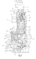
- Fig. 2 the operating state of the filtration operation of this filter element 9 is shown, wherein, as illustrated by flow arrows, the inflowing through the inlet 45 fluid enters the unfiltered portion 37, the backwash guide 21 flows around and via a chamber connection 53, which is located in the wall 41 of the housing main chamber , in the raw side 55 of the element chamber 7 passes.
- the fluid flows through the filter medium 57 from the outside inwards to the clean side 59 of the closed by a chamber lid 61 element chamber 7, from where the purified fluid via a chamber port 63rd to the filtrate side 35 and exits through the filter outlet 43 from the device.
- the Fig. 2 shows that in this operating state of the filtration, the piston 65 is located at the upper end of the cylinder 23 and the fluid chamber 67 adjoining the underside of the piston 65 has its largest volume.
- the chamber 67 as indicated by circular symbols, which are provided with transverse lines, is filled with a quantity of purified fluid, this filling quantity entering the filtration operation via a throttle 69 from the filtrate part 35 out into an inflow line 71, which in Inside the backwash guide 21 is formed and at one end to the adjacent fluid chamber 67 of the piston accumulator 13 is open.
- the other end of this inflow line 71 forms a radially outwardly projecting from the cylinder axis terminal end 73, which in the in Fig. 3 shown filtration operation is closed by contact with the inner wall 41 of the housing main part 1.
- the fluid chamber 79 adjacent to the upper end of the piston 65 has the smallest volume.
- This chamber 79 is for a backwash process, as in Fig. 3 is shown, can be acted upon with compressed air, which can be flowed into the chamber 79 from the gas pressure chamber 15 via a piston accumulator valve.
- a piston accumulator valve In the presentation of Fig. 2 is located within the end piece 47 movable valve piston 81 of the piston accumulator valve in its closed position.
- valve piston 81 in the upwardly moved open position in which its control edge 83 an air inlet 85 from the gas pressure chamber 15 her forth into the fluid chamber 79 releases to drive the accumulator piston 65 down.
- the valve piston 81 by pressure build-up in a valve chamber 87 can be raised by a control line 89 via a control pressure medium is supplied.
- a second control line 91 for the switching of the piston accumulator valve in the closed position there is a second control line 91, which opens at the top of the valve piston 81 in the valve chamber 87.
- the control lines 89 and 91 with a 5/2-way valve 93 ( Fig. 5 ), which in turn is connected to a control pressure source, which is not shown.
- a compressed gas connection 94 compressed air can be fed to the gas pressure chamber 15 from a 3/2-way valve 95.
- a venting port 97 on the directional control valve 95 allows a reduction of the gas pressure in the fluid chamber 79 when the piston accumulator valve is in the open position, so that during filtration operation the lower fluid chamber 67 of the piston accumulator 13 can be filled with cleaned fluid via the throttle 69, wherein the accumulator piston 65 moves upwards emotional.
- the backwash guide 21 is in a rotational position at which the connection ends 73 and 77 of the inflow line 71 and the outflow line 75 coincide with the chamber connections 63 and 53, respectively the element chamber 7 are located.
- the piston accumulator valve is in its open position, so that, as with flow arrows in Fig.
- pressurized gas flows into the fluid chamber 79 of the piston accumulator, the accumulator piston 65 moves down and the fluid located in the fluid chamber 67, cleaned fluid passes as Ruthêtmenge via the inflow line 71 to the clean side 59 of the element chamber 7, wherein a generated by the acting compressed air pressure greedströmung high intensity is generated, which flows through the filter element 9 to be cleaned from the inside out and deters dirt particles from the outside of the filter medium 57 to discharge the contaminants via the discharge line 75 and the Ruthêtauslass 27.
- the backwash line 29 is unlocked in each case via the engine valve 31.
- the backwash line 29 is again blocked, and the compressed air supply is terminated by means of the valve 95, while the valve piston 81 of the piston accumulator valve remains in the open position and the ventilation port 97 is open at the directional control valve 95 , so that the compressed air pressure in the gas pressure chamber 15 and in the fluid chamber 79 is degraded again.
- the fluid chamber 67 is loaded via the throttle 69 again with purified fluid, while the accumulator piston 65 moves upward.
- the piston accumulator valve is closed again by the valve piston 81 is moved down, and the gas pressure chamber 15 is supplied via the directional control valve 95, with closed ventilation port 97 again with compressed air, so that the device for a subsequent backwashing ready is.
Landscapes
- Chemical & Material Sciences (AREA)
- Chemical Kinetics & Catalysis (AREA)
- Filtering Of Dispersed Particles In Gases (AREA)
- Filtration Of Liquid (AREA)
- Fluid-Pressure Circuits (AREA)
Claims (11)
- Système (1) de filtration, comprenant une pluralité d'éléments (9) filtrants, qui peuvent être reçus dans une enveloppe (1) de filtre, ayant une entrée (45) de filtre pour le fluide à filtrer et une sortie (43) de filtre pour le fluide filtré, dans lequel, pendant l'opération de filtration, au moins l'un des éléments (9) filtrants peut être lavé en retour pour nettoyer sa surface filtrante active au moyen d'un dispositif (13, 21) de lavage en retour, qui comporte un dispositif (13) de commande de la pression pour assister le lavage en retour, dans lequel le dispositif de commande de la pression comporte un accumulateur (13) hydraulique, dont une chambre (67) de fluide peut, pendant l'opération de filtration, être remplie d'une quantité de fluide épurée et peut, pour une opération de lavage en retour, être reliée, par l'intermédiaire d'un conduit (21) de lavage en retour, au côté (59) propre du au moins un élément (9) filtrant à nettoyer, et dans lequel une autre chambre (79) de fluide de l'accumulateur (13) hydraulique peut, pour une opération de lavage en retour, être soumise à une pression de fluide, afin de recéder, par un déplacement ainsi provoqué d'un élément (65) de séparation de l'accumulateur (13) hydraulique, la quantité de remplissage du fluide épuré pour l'opération de lavage en retour, au moins en partie, de la première chambre (67) de fluide, la chambre (67) de fluide, recevant la quantité de fluide épuré, de l'accumulateur (13) hydraulique pouvant être remplie par l'intermédiaire d'un dispositif (69) d'étranglement, caractérisé en ce que le dispositif (69) d'étranglement se trouve entre une partie (35) de filtrat d'un espace principal de l'enveloppe (1) de filtre et une ligne (71) d'afflux du conduit (21) de lavage en retour.
- Système de filtration suivant la revendication 1, caractérisé en ce que l'autre chambre (79) de fluide de l'accumulateur (13) hydraulique peut, pour l'opération de lavage en retour, être, au moyen d'un dispositif (81, 93, 95) de soupape, mise en communication avec une source de pression de fluide, notamment sous la forme d'une source de gaz comprimé.
- Système de filtration suivant la revendication 1 ou 2, caractérisé en ce que l'accumulateur (13) hydraulique et le conduit (21) de lavage en retour sont montés tournants en communiquant entre eux dans l'enveloppe (1, 3) de filtre et, pour des déplacements de réglage, peuvent passer entre un fonctionnement en filtration et en lavage en retour au moyen de l'entraînement (5) en rotation.
- Système de filtration suivant l'une des revendications précédentes, caractérisé en ce qu'il est prévu, comme accumulateur hydraulique, un accumulateur (13) à piston, qui peut tourner autour de l'axe d'un cylindre, ensemble avec le conduit (21) de lavage en retour monté à une extrémité (11) du cylindre.
- Système de filtration suivant l'une des revendications précédentes, caractérisé en ce que les éléments (9) filtrants peuvent être reçus chacun dans leur propre chambre (7), qui sont disposées dans l'enveloppe (1) du filtre sur une ligne circulaire entourant concentriquement l'axe du cylindre.
- Système de filtration suivant la revendication 5, caractérisé en ce que les chambres (7) d'éléments ont un premier raccord (63) de chambre, relié au côté (59) propre de l'élément (9) filtrant, et un deuxième raccord (53) de chambre, relié au côté (55) brut, et en ce que ces deux raccords sont ouverts vers un espace principal de l'enveloppe (1) de filtre, dans lequel le conduit (21) de lavage en retour tournant s'étend sous la forme d'un organe de commutation, dont les déplacements de réglage règlent, pour le lavage en retour, l'arrivée et la sortie de fluide allant au premier raccord (63) et au deuxième raccord (53) et en revenant.
- Système de filtration suivant l'une des revendications précédentes, caractérisé en ce que le lavage (21) en retour a, à une distance axiale de l'accumulateur (13) à piston et à partir de son extrémité opposée, un corps (33) annulaire formant une saillie radiale et ayant une étanchéité (39) radiale périphérique, qui, ensemble avec une paroi (41) de l'espace principal, sépare celui-ci en une partie (35) de filtrat ayant la sortie (43) du filtre et une partie (37) de non filtrat ayant l'entrée (45) du filtre.
- Système de filtration suivant la revendication 6, caractérisé en ce que l'embouchure du premier et du deuxième raccord (63 et 53) de chambre se trouve sur une paroi (41), formant une surface de cylindre, de la partie (35) de filtrat ou de la partie (37) de non filtrat de l'espace principal et en ce que, lors du réglage sur le lavage en retour, des extrémités (73, 77) de raccordement, en porte à faux de l'axe du cylindre, de lignes (71) d'arrivée et de lignes (75) d'évacuation formées sur le conduit (21) de lavage en retour, viennent en coïncidence avec les raccords (63, 53) de chambre, la ligne (71) d'arrivée formant la communication de la première chambre (67) de fluide de l'accumulateur (13) à piston avec le premier raccord (63) de chambre, et la ligne (75) d'évacuation, la communication du deuxième raccord (53) de chambre avec une sortie (27) de lavage en retour de l'espace principal.
- Système de filtration suivant la revendication 8, caractérisé en ce que la sortie (27) de lavage en retour peut être obturée et dégagée au moyen d'un système (31) de soupape.
- Système de filtration suivant l'une des revendications 2 à 9, caractérisé en ce qu'une commande de soupape a une soupape pouvant être actionnée par un fluide sous pression, de préférence sous la forme d'une soupape (93) à 5/2 voies, qui commande la communication avec la source de pression concernée de la chambre (79) de fluide, pouvant être alimentée en fluide sous pression, de l'accumulateur (13) hydraulique.
- Système de filtration suivant l'une des revendications 2 à 10, caractérisé en ce qu'une autre soupape, de préférence sous la forme d'une soupape (95) à 3/2 voies, par laquelle la chambre (79) de fluide de l'accumulateur (13) hydraulique peut communiquer avec la source sous pression, permet un établissement, au choix, de la pression de fluide dans l'accumulateur (13) hydraulique.
Applications Claiming Priority (2)
| Application Number | Priority Date | Filing Date | Title |
|---|---|---|---|
| DE102011100518A DE102011100518A1 (de) | 2011-05-05 | 2011-05-05 | Filtervorrichtung |
| PCT/EP2012/001772 WO2012150010A1 (fr) | 2011-05-05 | 2012-04-26 | Dispositif filtrant |
Publications (2)
| Publication Number | Publication Date |
|---|---|
| EP2704812A1 EP2704812A1 (fr) | 2014-03-12 |
| EP2704812B1 true EP2704812B1 (fr) | 2019-02-20 |
Family
ID=46027902
Family Applications (2)
| Application Number | Title | Priority Date | Filing Date |
|---|---|---|---|
| EP12718912.4A Active EP2704811B1 (fr) | 2011-05-05 | 2012-04-26 | Dispositif filtrant |
| EP12724887.0A Active EP2704812B1 (fr) | 2011-05-05 | 2012-04-26 | Dispositif filtrant |
Family Applications Before (1)
| Application Number | Title | Priority Date | Filing Date |
|---|---|---|---|
| EP12718912.4A Active EP2704811B1 (fr) | 2011-05-05 | 2012-04-26 | Dispositif filtrant |
Country Status (9)
| Country | Link |
|---|---|
| US (2) | US11058975B2 (fr) |
| EP (2) | EP2704811B1 (fr) |
| JP (2) | JP6006295B2 (fr) |
| KR (2) | KR101961088B1 (fr) |
| CN (2) | CN103517744B (fr) |
| DE (1) | DE102011100518A1 (fr) |
| DK (2) | DK2704811T3 (fr) |
| PL (1) | PL2704811T3 (fr) |
| WO (2) | WO2012150011A1 (fr) |
Families Citing this family (10)
| Publication number | Priority date | Publication date | Assignee | Title |
|---|---|---|---|---|
| CN103100254B (zh) * | 2013-02-05 | 2015-05-20 | 品孚罗特过滤设备(北京)有限公司 | 一种不间断过滤的过滤装置 |
| DE102015002767A1 (de) * | 2015-03-05 | 2016-09-08 | Hydac Process Technology Gmbh | Filtervorrichtung |
| DE102015015237A1 (de) * | 2015-11-25 | 2017-06-01 | Hydac Process Technology Gmbh | Filtervorrichtung |
| DE102017002646A1 (de) * | 2017-03-18 | 2018-09-20 | Hydac Process Technology Gmbh | Filtervorrichtung |
| IL251485A0 (en) * | 2017-03-30 | 2017-05-29 | אוליאל ערן | water filter |
| US10307698B2 (en) * | 2017-05-03 | 2019-06-04 | Jacob H. Berg | Multiple cartridge fluid filter canister |
| DE102017004661A1 (de) * | 2017-05-08 | 2018-11-08 | Hydac Process Technology Gmbh | Filtervorrichtung |
| DE102017009990A1 (de) * | 2017-10-26 | 2019-05-02 | Hydac Process Technology Gmbh | Filtervorrichtung |
| DE102023003883A1 (de) | 2023-09-25 | 2025-03-27 | Hydac Process Technology Gmbh | System |
| GB2644073A (en) * | 2024-09-13 | 2026-03-18 | Inheriting Earth Ltd | System for separating particulates from a fluid and method |
Family Cites Families (18)
| Publication number | Priority date | Publication date | Assignee | Title |
|---|---|---|---|---|
| US2731107A (en) * | 1954-05-07 | 1956-01-17 | Jr Henry J Hersey | Filter |
| FR83147E (fr) * | 1961-05-12 | 1964-06-19 | Procédé et dispositifs de décolmatage de filtres disposés dans des circuits de fluides fonctionnant sous pression ou sous vide | |
| DE1241803B (de) * | 1963-03-04 | 1967-06-08 | Muller Jacques | Absperrvorrichtung zum automatischen, periodischen Entschlammen von Filterkerzen durch Rueckspuelung |
| FR1437838A (fr) * | 1965-06-11 | 1966-05-06 | Filtre comportant un dispositif de nettoyage automatique pour tous fluides | |
| US4055500A (en) * | 1976-02-10 | 1977-10-25 | Parker Leland L | Filtering apparatus and quick-opening backwash valve therefor |
| JPS63119820A (ja) * | 1986-11-10 | 1988-05-24 | Koyago Takasuke | 全自動濾過装置 |
| DE3832679A1 (de) * | 1988-09-27 | 1990-03-29 | Boll & Kirch Filter | Rueckspuelfilter |
| DE4030084C2 (de) * | 1990-09-22 | 1999-09-30 | Boll & Kirch Filter | Rückspülfilter |
| DE4345412C2 (de) * | 1993-11-26 | 1999-11-11 | Boll & Kirch Filter | Filterkerze |
| DE19636254C2 (de) * | 1996-09-06 | 1999-01-14 | Premark Feg L L C N D Ges D St | Vorrichtung und Verfahren zum Filtern von Suspensionen |
| US5906751A (en) * | 1997-10-10 | 1999-05-25 | Parker; Leland L. | Filtering apparatus with improved quick-opening backwash valve |
| FI107127B (fi) * | 1999-11-11 | 2001-06-15 | Parker Hannifin Oy | Menetelmä ja laitteisto nesteen suodattamiseksi |
| DE19956859A1 (de) * | 1999-11-25 | 2001-06-07 | Hydac Filtertechnik Gmbh | Rückspülfiltervorrichtung |
| US6461525B2 (en) * | 2000-08-01 | 2002-10-08 | Tetra Process Technologies | Method for backwashing granular media filters and bioreactors |
| DE10325525B4 (de) * | 2003-06-04 | 2013-10-24 | Boll & Kirch Filterbau Gmbh | Rückspülfilter |
| DE102007019222B3 (de) * | 2007-04-24 | 2008-10-23 | Bela Seebach | Filteranlage mit Rückspüleinrichtung |
| DE102007054737A1 (de) | 2007-11-16 | 2009-05-20 | Hydac Process Technology Gmbh | Filtervorrichtung |
| US20100101269A1 (en) * | 2008-10-24 | 2010-04-29 | Theodore Jr Michael | Compressor with improved oil separation |
-
2011
- 2011-05-05 DE DE102011100518A patent/DE102011100518A1/de not_active Withdrawn
-
2012
- 2012-04-26 CN CN201280021885.2A patent/CN103517744B/zh active Active
- 2012-04-26 US US13/261,770 patent/US11058975B2/en active Active
- 2012-04-26 JP JP2014508706A patent/JP6006295B2/ja active Active
- 2012-04-26 EP EP12718912.4A patent/EP2704811B1/fr active Active
- 2012-04-26 DK DK12718912.4T patent/DK2704811T3/en active
- 2012-04-26 WO PCT/EP2012/001773 patent/WO2012150011A1/fr not_active Ceased
- 2012-04-26 US US13/261,764 patent/US9855520B2/en active Active
- 2012-04-26 JP JP2014508705A patent/JP6158790B2/ja active Active
- 2012-04-26 KR KR1020137032066A patent/KR101961088B1/ko active Active
- 2012-04-26 WO PCT/EP2012/001772 patent/WO2012150010A1/fr not_active Ceased
- 2012-04-26 DK DK12724887.0T patent/DK2704812T3/da active
- 2012-04-26 EP EP12724887.0A patent/EP2704812B1/fr active Active
- 2012-04-26 KR KR1020137032075A patent/KR101950167B1/ko active Active
- 2012-04-26 PL PL12718912T patent/PL2704811T3/pl unknown
- 2012-04-26 CN CN201280021848.1A patent/CN103561837B/zh active Active
Non-Patent Citations (1)
| Title |
|---|
| None * |
Also Published As
| Publication number | Publication date |
|---|---|
| US9855520B2 (en) | 2018-01-02 |
| KR20140038977A (ko) | 2014-03-31 |
| US20140202938A1 (en) | 2014-07-24 |
| EP2704811B1 (fr) | 2017-11-08 |
| DK2704812T3 (da) | 2019-05-13 |
| PL2704811T3 (pl) | 2018-04-30 |
| JP2014516772A (ja) | 2014-07-17 |
| WO2012150010A1 (fr) | 2012-11-08 |
| JP6158790B2 (ja) | 2017-07-05 |
| US20140091021A1 (en) | 2014-04-03 |
| EP2704811A1 (fr) | 2014-03-12 |
| KR20140038976A (ko) | 2014-03-31 |
| JP2014512953A (ja) | 2014-05-29 |
| KR101950167B1 (ko) | 2019-02-20 |
| JP6006295B2 (ja) | 2016-10-12 |
| DE102011100518A1 (de) | 2012-11-08 |
| CN103561837A (zh) | 2014-02-05 |
| WO2012150011A8 (fr) | 2013-01-24 |
| EP2704812A1 (fr) | 2014-03-12 |
| CN103517744B (zh) | 2016-08-24 |
| KR101961088B1 (ko) | 2019-03-25 |
| WO2012150011A1 (fr) | 2012-11-08 |
| US11058975B2 (en) | 2021-07-13 |
| DK2704811T3 (en) | 2017-12-18 |
| CN103517744A (zh) | 2014-01-15 |
| CN103561837B (zh) | 2016-08-17 |
Similar Documents
| Publication | Publication Date | Title |
|---|---|---|
| EP2704812B1 (fr) | Dispositif filtrant | |
| DE10151864B4 (de) | Verfahren zum Betrieb eines Filters für Flüssigkeiten und System zur Durchführung des Verfahrens | |
| EP1237640B1 (fr) | Dispositif filtrant a retrolavage | |
| DE102011111457B4 (de) | Filtervorrichtung | |
| EP2207609B1 (fr) | Dispositif de filtration | |
| EP2448647B1 (fr) | Dispositif de filtration | |
| DE112014006168T5 (de) | Filterelement und Filtervorrichtung | |
| DE1761106C3 (de) | Filter zur Reinigung von mit Feststoffen vermischten Flüssigkeiten | |
| EP0875286B1 (fr) | Dispositif de filtrage avec module à membrane | |
| DE1241802B (de) | Filterapparat | |
| DE10340366B4 (de) | Filtervorrichtung | |
| DE102007003925A1 (de) | Filteranlage | |
| DE19542578A1 (de) | Rückspülbare Filtervorrichtung mit Druckgas | |
| DE1786118A1 (de) | Selbstreinigende Filtervorrichtung | |
| EP3380212B1 (fr) | Dispositif de filtration | |
| EP2364761B1 (fr) | Filtre à lavage à contre-courant | |
| DE77145C (de) | Trommelfilter | |
| EP3838371B1 (fr) | Filtre à fluide et procédé de nettoyage de filtre | |
| DE20220668U1 (de) | System zur Regeneration eines Filtermittels eines Filters | |
| EP4115964B1 (fr) | Dispositif filtre | |
| DE7435463U (de) | Druckfilter für Trüben | |
| DE69615380T2 (de) | Selbstreinigender filter zum filtrieren von flüssigkeiten und gasen | |
| DE3245093A1 (de) | Rueckspuelfilter | |
| DE20014299U1 (de) | Rückspülfilter für flüssige Medien | |
| DE202022105162U1 (de) | Druckfilterbehälter |
Legal Events
| Date | Code | Title | Description |
|---|---|---|---|
| PUAI | Public reference made under article 153(3) epc to a published international application that has entered the european phase |
Free format text: ORIGINAL CODE: 0009012 |
|
| 17P | Request for examination filed |
Effective date: 20131004 |
|
| AK | Designated contracting states |
Kind code of ref document: A1 Designated state(s): AL AT BE BG CH CY CZ DE DK EE ES FI FR GB GR HR HU IE IS IT LI LT LU LV MC MK MT NL NO PL PT RO RS SE SI SK SM TR |
|
| DAX | Request for extension of the european patent (deleted) | ||
| 17Q | First examination report despatched |
Effective date: 20160630 |
|
| STAA | Information on the status of an ep patent application or granted ep patent |
Free format text: STATUS: EXAMINATION IS IN PROGRESS |
|
| GRAP | Despatch of communication of intention to grant a patent |
Free format text: ORIGINAL CODE: EPIDOSNIGR1 |
|
| STAA | Information on the status of an ep patent application or granted ep patent |
Free format text: STATUS: GRANT OF PATENT IS INTENDED |
|
| INTG | Intention to grant announced |
Effective date: 20180928 |
|
| GRAS | Grant fee paid |
Free format text: ORIGINAL CODE: EPIDOSNIGR3 |
|
| GRAA | (expected) grant |
Free format text: ORIGINAL CODE: 0009210 |
|
| STAA | Information on the status of an ep patent application or granted ep patent |
Free format text: STATUS: THE PATENT HAS BEEN GRANTED |
|
| AK | Designated contracting states |
Kind code of ref document: B1 Designated state(s): AL AT BE BG CH CY CZ DE DK EE ES FI FR GB GR HR HU IE IS IT LI LT LU LV MC MK MT NL NO PL PT RO RS SE SI SK SM TR |
|
| REG | Reference to a national code |
Ref country code: GB Ref legal event code: FG4D Free format text: NOT ENGLISH |
|
| REG | Reference to a national code |
Ref country code: CH Ref legal event code: EP |
|
| REG | Reference to a national code |
Ref country code: DE Ref legal event code: R096 Ref document number: 502012014290 Country of ref document: DE |
|
| REG | Reference to a national code |
Ref country code: AT Ref legal event code: REF Ref document number: 1097426 Country of ref document: AT Kind code of ref document: T Effective date: 20190315 |
|
| REG | Reference to a national code |
Ref country code: IE Ref legal event code: FG4D Free format text: LANGUAGE OF EP DOCUMENT: GERMAN |
|
| REG | Reference to a national code |
Ref country code: DK Ref legal event code: T3 Effective date: 20190506 |
|
| REG | Reference to a national code |
Ref country code: SE Ref legal event code: TRGR |
|
| REG | Reference to a national code |
Ref country code: NL Ref legal event code: MP Effective date: 20190220 |
|
| REG | Reference to a national code |
Ref country code: LT Ref legal event code: MG4D |
|
| PG25 | Lapsed in a contracting state [announced via postgrant information from national office to epo] |
Ref country code: NO Free format text: LAPSE BECAUSE OF FAILURE TO SUBMIT A TRANSLATION OF THE DESCRIPTION OR TO PAY THE FEE WITHIN THE PRESCRIBED TIME-LIMIT Effective date: 20190520 Ref country code: PT Free format text: LAPSE BECAUSE OF FAILURE TO SUBMIT A TRANSLATION OF THE DESCRIPTION OR TO PAY THE FEE WITHIN THE PRESCRIBED TIME-LIMIT Effective date: 20190620 Ref country code: LT Free format text: LAPSE BECAUSE OF FAILURE TO SUBMIT A TRANSLATION OF THE DESCRIPTION OR TO PAY THE FEE WITHIN THE PRESCRIBED TIME-LIMIT Effective date: 20190220 Ref country code: NL Free format text: LAPSE BECAUSE OF FAILURE TO SUBMIT A TRANSLATION OF THE DESCRIPTION OR TO PAY THE FEE WITHIN THE PRESCRIBED TIME-LIMIT Effective date: 20190220 |
|
| PG25 | Lapsed in a contracting state [announced via postgrant information from national office to epo] |
Ref country code: IS Free format text: LAPSE BECAUSE OF FAILURE TO SUBMIT A TRANSLATION OF THE DESCRIPTION OR TO PAY THE FEE WITHIN THE PRESCRIBED TIME-LIMIT Effective date: 20190620 Ref country code: BG Free format text: LAPSE BECAUSE OF FAILURE TO SUBMIT A TRANSLATION OF THE DESCRIPTION OR TO PAY THE FEE WITHIN THE PRESCRIBED TIME-LIMIT Effective date: 20190520 Ref country code: GR Free format text: LAPSE BECAUSE OF FAILURE TO SUBMIT A TRANSLATION OF THE DESCRIPTION OR TO PAY THE FEE WITHIN THE PRESCRIBED TIME-LIMIT Effective date: 20190521 Ref country code: LV Free format text: LAPSE BECAUSE OF FAILURE TO SUBMIT A TRANSLATION OF THE DESCRIPTION OR TO PAY THE FEE WITHIN THE PRESCRIBED TIME-LIMIT Effective date: 20190220 Ref country code: RS Free format text: LAPSE BECAUSE OF FAILURE TO SUBMIT A TRANSLATION OF THE DESCRIPTION OR TO PAY THE FEE WITHIN THE PRESCRIBED TIME-LIMIT Effective date: 20190220 Ref country code: HR Free format text: LAPSE BECAUSE OF FAILURE TO SUBMIT A TRANSLATION OF THE DESCRIPTION OR TO PAY THE FEE WITHIN THE PRESCRIBED TIME-LIMIT Effective date: 20190220 |
|
| PG25 | Lapsed in a contracting state [announced via postgrant information from national office to epo] |
Ref country code: CZ Free format text: LAPSE BECAUSE OF FAILURE TO SUBMIT A TRANSLATION OF THE DESCRIPTION OR TO PAY THE FEE WITHIN THE PRESCRIBED TIME-LIMIT Effective date: 20190220 Ref country code: RO Free format text: LAPSE BECAUSE OF FAILURE TO SUBMIT A TRANSLATION OF THE DESCRIPTION OR TO PAY THE FEE WITHIN THE PRESCRIBED TIME-LIMIT Effective date: 20190220 Ref country code: SK Free format text: LAPSE BECAUSE OF FAILURE TO SUBMIT A TRANSLATION OF THE DESCRIPTION OR TO PAY THE FEE WITHIN THE PRESCRIBED TIME-LIMIT Effective date: 20190220 Ref country code: AL Free format text: LAPSE BECAUSE OF FAILURE TO SUBMIT A TRANSLATION OF THE DESCRIPTION OR TO PAY THE FEE WITHIN THE PRESCRIBED TIME-LIMIT Effective date: 20190220 Ref country code: EE Free format text: LAPSE BECAUSE OF FAILURE TO SUBMIT A TRANSLATION OF THE DESCRIPTION OR TO PAY THE FEE WITHIN THE PRESCRIBED TIME-LIMIT Effective date: 20190220 Ref country code: ES Free format text: LAPSE BECAUSE OF FAILURE TO SUBMIT A TRANSLATION OF THE DESCRIPTION OR TO PAY THE FEE WITHIN THE PRESCRIBED TIME-LIMIT Effective date: 20190220 |
|
| REG | Reference to a national code |
Ref country code: DE Ref legal event code: R097 Ref document number: 502012014290 Country of ref document: DE |
|
| PG25 | Lapsed in a contracting state [announced via postgrant information from national office to epo] |
Ref country code: PL Free format text: LAPSE BECAUSE OF FAILURE TO SUBMIT A TRANSLATION OF THE DESCRIPTION OR TO PAY THE FEE WITHIN THE PRESCRIBED TIME-LIMIT Effective date: 20190220 Ref country code: SM Free format text: LAPSE BECAUSE OF FAILURE TO SUBMIT A TRANSLATION OF THE DESCRIPTION OR TO PAY THE FEE WITHIN THE PRESCRIBED TIME-LIMIT Effective date: 20190220 |
|
| REG | Reference to a national code |
Ref country code: CH Ref legal event code: PL |
|
| REG | Reference to a national code |
Ref country code: BE Ref legal event code: MM Effective date: 20190430 |
|
| PLBE | No opposition filed within time limit |
Free format text: ORIGINAL CODE: 0009261 |
|
| STAA | Information on the status of an ep patent application or granted ep patent |
Free format text: STATUS: NO OPPOSITION FILED WITHIN TIME LIMIT |
|
| PG25 | Lapsed in a contracting state [announced via postgrant information from national office to epo] |
Ref country code: MC Free format text: LAPSE BECAUSE OF FAILURE TO SUBMIT A TRANSLATION OF THE DESCRIPTION OR TO PAY THE FEE WITHIN THE PRESCRIBED TIME-LIMIT Effective date: 20190220 Ref country code: LU Free format text: LAPSE BECAUSE OF NON-PAYMENT OF DUE FEES Effective date: 20190426 |
|
| 26N | No opposition filed |
Effective date: 20191121 |
|
| PG25 | Lapsed in a contracting state [announced via postgrant information from national office to epo] |
Ref country code: LI Free format text: LAPSE BECAUSE OF NON-PAYMENT OF DUE FEES Effective date: 20190430 Ref country code: CH Free format text: LAPSE BECAUSE OF NON-PAYMENT OF DUE FEES Effective date: 20190430 |
|
| PG25 | Lapsed in a contracting state [announced via postgrant information from national office to epo] |
Ref country code: SI Free format text: LAPSE BECAUSE OF FAILURE TO SUBMIT A TRANSLATION OF THE DESCRIPTION OR TO PAY THE FEE WITHIN THE PRESCRIBED TIME-LIMIT Effective date: 20190220 Ref country code: BE Free format text: LAPSE BECAUSE OF NON-PAYMENT OF DUE FEES Effective date: 20190430 |
|
| PG25 | Lapsed in a contracting state [announced via postgrant information from national office to epo] |
Ref country code: TR Free format text: LAPSE BECAUSE OF FAILURE TO SUBMIT A TRANSLATION OF THE DESCRIPTION OR TO PAY THE FEE WITHIN THE PRESCRIBED TIME-LIMIT Effective date: 20190220 |
|
| PG25 | Lapsed in a contracting state [announced via postgrant information from national office to epo] |
Ref country code: IE Free format text: LAPSE BECAUSE OF NON-PAYMENT OF DUE FEES Effective date: 20190426 |
|
| REG | Reference to a national code |
Ref country code: AT Ref legal event code: MM01 Ref document number: 1097426 Country of ref document: AT Kind code of ref document: T Effective date: 20190426 |
|
| PG25 | Lapsed in a contracting state [announced via postgrant information from national office to epo] |
Ref country code: AT Free format text: LAPSE BECAUSE OF NON-PAYMENT OF DUE FEES Effective date: 20190426 |
|
| PG25 | Lapsed in a contracting state [announced via postgrant information from national office to epo] |
Ref country code: CY Free format text: LAPSE BECAUSE OF FAILURE TO SUBMIT A TRANSLATION OF THE DESCRIPTION OR TO PAY THE FEE WITHIN THE PRESCRIBED TIME-LIMIT Effective date: 20190220 |
|
| PG25 | Lapsed in a contracting state [announced via postgrant information from national office to epo] |
Ref country code: MT Free format text: LAPSE BECAUSE OF FAILURE TO SUBMIT A TRANSLATION OF THE DESCRIPTION OR TO PAY THE FEE WITHIN THE PRESCRIBED TIME-LIMIT Effective date: 20190220 Ref country code: HU Free format text: LAPSE BECAUSE OF FAILURE TO SUBMIT A TRANSLATION OF THE DESCRIPTION OR TO PAY THE FEE WITHIN THE PRESCRIBED TIME-LIMIT; INVALID AB INITIO Effective date: 20120426 |
|
| PG25 | Lapsed in a contracting state [announced via postgrant information from national office to epo] |
Ref country code: MK Free format text: LAPSE BECAUSE OF FAILURE TO SUBMIT A TRANSLATION OF THE DESCRIPTION OR TO PAY THE FEE WITHIN THE PRESCRIBED TIME-LIMIT Effective date: 20190220 |
|
| PGFP | Annual fee paid to national office [announced via postgrant information from national office to epo] |
Ref country code: FR Payment date: 20250317 Year of fee payment: 14 |
|
| PGFP | Annual fee paid to national office [announced via postgrant information from national office to epo] |
Ref country code: DE Payment date: 20250430 Year of fee payment: 14 |
|
| PGFP | Annual fee paid to national office [announced via postgrant information from national office to epo] |
Ref country code: IT Payment date: 20250407 Year of fee payment: 14 |
|
| PGFP | Annual fee paid to national office [announced via postgrant information from national office to epo] |
Ref country code: SE Payment date: 20260205 Year of fee payment: 15 |
|
| PGFP | Annual fee paid to national office [announced via postgrant information from national office to epo] |
Ref country code: GB Payment date: 20260210 Year of fee payment: 15 |
|
| PGFP | Annual fee paid to national office [announced via postgrant information from national office to epo] |
Ref country code: DK Payment date: 20260209 Year of fee payment: 15 |
|
| PGFP | Annual fee paid to national office [announced via postgrant information from national office to epo] |
Ref country code: FI Payment date: 20260206 Year of fee payment: 15 |