EP2705268B1 - Parcours hydraulique doté d'un dispositif d'évacuation de l'air - Google Patents
Parcours hydraulique doté d'un dispositif d'évacuation de l'air Download PDFInfo
- Publication number
- EP2705268B1 EP2705268B1 EP12728372.9A EP12728372A EP2705268B1 EP 2705268 B1 EP2705268 B1 EP 2705268B1 EP 12728372 A EP12728372 A EP 12728372A EP 2705268 B1 EP2705268 B1 EP 2705268B1
- Authority
- EP
- European Patent Office
- Prior art keywords
- hydraulic
- line
- section
- housing
- hydraulic section
- Prior art date
- Legal status (The legal status is an assumption and is not a legal conclusion. Google has not performed a legal analysis and makes no representation as to the accuracy of the status listed.)
- Active
Links
Images

Classifications
-
- F—MECHANICAL ENGINEERING; LIGHTING; HEATING; WEAPONS; BLASTING
- F16—ENGINEERING ELEMENTS AND UNITS; GENERAL MEASURES FOR PRODUCING AND MAINTAINING EFFECTIVE FUNCTIONING OF MACHINES OR INSTALLATIONS; THERMAL INSULATION IN GENERAL
- F16D—COUPLINGS FOR TRANSMITTING ROTATION; CLUTCHES; BRAKES
- F16D25/00—Fluid-actuated clutches
- F16D25/12—Details not specific to one of the before-mentioned types
-
- F—MECHANICAL ENGINEERING; LIGHTING; HEATING; WEAPONS; BLASTING
- F16—ENGINEERING ELEMENTS AND UNITS; GENERAL MEASURES FOR PRODUCING AND MAINTAINING EFFECTIVE FUNCTIONING OF MACHINES OR INSTALLATIONS; THERMAL INSULATION IN GENERAL
- F16D—COUPLINGS FOR TRANSMITTING ROTATION; CLUTCHES; BRAKES
- F16D48/00—External control of clutches
- F16D48/02—Control by fluid pressure
-
- F—MECHANICAL ENGINEERING; LIGHTING; HEATING; WEAPONS; BLASTING
- F16—ENGINEERING ELEMENTS AND UNITS; GENERAL MEASURES FOR PRODUCING AND MAINTAINING EFFECTIVE FUNCTIONING OF MACHINES OR INSTALLATIONS; THERMAL INSULATION IN GENERAL
- F16D—COUPLINGS FOR TRANSMITTING ROTATION; CLUTCHES; BRAKES
- F16D48/00—External control of clutches
- F16D48/02—Control by fluid pressure
- F16D2048/0212—Details of pistons for primary or secondary cylinders especially adapted for fluid control
-
- F—MECHANICAL ENGINEERING; LIGHTING; HEATING; WEAPONS; BLASTING
- F16—ENGINEERING ELEMENTS AND UNITS; GENERAL MEASURES FOR PRODUCING AND MAINTAINING EFFECTIVE FUNCTIONING OF MACHINES OR INSTALLATIONS; THERMAL INSULATION IN GENERAL
- F16D—COUPLINGS FOR TRANSMITTING ROTATION; CLUTCHES; BRAKES
- F16D2500/00—External control of clutches by electric or electronic means
- F16D2500/50—Problem to be solved by the control system
- F16D2500/501—Relating the actuator
- F16D2500/5016—Shifting operation, i.e. volume compensation of the primary cylinder due to wear, temperature changes or leaks in the cylinder
-
- F—MECHANICAL ENGINEERING; LIGHTING; HEATING; WEAPONS; BLASTING
- F16—ENGINEERING ELEMENTS AND UNITS; GENERAL MEASURES FOR PRODUCING AND MAINTAINING EFFECTIVE FUNCTIONING OF MACHINES OR INSTALLATIONS; THERMAL INSULATION IN GENERAL
- F16D—COUPLINGS FOR TRANSMITTING ROTATION; CLUTCHES; BRAKES
- F16D2500/00—External control of clutches by electric or electronic means
- F16D2500/50—Problem to be solved by the control system
- F16D2500/51—Relating safety
- F16D2500/5118—Maintenance
-
- F—MECHANICAL ENGINEERING; LIGHTING; HEATING; WEAPONS; BLASTING
- F16—ENGINEERING ELEMENTS AND UNITS; GENERAL MEASURES FOR PRODUCING AND MAINTAINING EFFECTIVE FUNCTIONING OF MACHINES OR INSTALLATIONS; THERMAL INSULATION IN GENERAL
- F16L—PIPES; JOINTS OR FITTINGS FOR PIPES; SUPPORTS FOR PIPES, CABLES OR PROTECTIVE TUBING; MEANS FOR THERMAL INSULATION IN GENERAL
- F16L33/00—Arrangements for connecting hoses to rigid members; Rigid hose-connectors, i.e. single members engaging both hoses
- F16L33/20—Undivided rings, sleeves, or like members contracted on the hose or expanded inside the hose by means of tools; Arrangements using such members
- F16L33/207—Undivided rings, sleeves, or like members contracted on the hose or expanded inside the hose by means of tools; Arrangements using such members only a sleeve being contracted on the hose
Definitions
- the invention relates to a hydraulic path for actuating a vehicle clutch having the features of the preamble of claim 1.
- Such a hydraulic stretch is eg off EP-A-1 978 271 known.
- the object of the invention is to realize a hydraulic path for actuating a vehicle clutch, the venting is ensured during operation via the master cylinder, without using an additional component and without steadily increasing the hydraulic line in the direction of master cylinder.
- a hydraulic path for actuating a vehicle clutch with a master cylinder, a slave cylinder and a hydraulic cylinder connecting the two cylinders is divided by a venting device into two line sections, which act as a sipe and riser line sections of the hydraulic line in one of at least one of these ends formed space to this venting device spaced from each other out together.
- the end Siffons is designed as a plug of the venting device and executed the end of the riser as a housing.
- the end of acting as a sipe line section of the hydraulic line opens with its bore side up in the room and the lower inner wall of the end of the bore of acting as a riser line section of the hydraulic line in the radial direction forms the lower boundary of the room.
- a further advantageous embodiment of the invention provides that the bore is continued with a length in the housing and the inner diameter of the housing is widened over at least a portion of this length in the radial direction.
- the bore is not continued in the housing formed, but ends at this, if it is, for example, an integrated into the hydraulic system separate component with a housing.
- the radial extension of the inner diameter of the housing forms the space in the housing in the axial direction at least over this area.
- the venting device is arranged in the hydraulic line at the highest point of the line section coming from the slave cylinder.
- the limitation of the space in the axial direction in the interior of the housing is advantageously formed by the end face of the inserted into the housing connector.
- a further advantageous embodiment of the invention provides that the hydraulic route is provided with a plurality of venting devices.
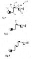
- the Figures 1 and 2 show a hydraulic line 1 for clutch actuation in two different operating positions.
- the hydraulic line 1 consists essentially of a master cylinder 3 and a slave cylinder 2. These are connected to each other via a hydraulic line 4.
- the hydraulic line 4 is rising in the direction of slave cylinder 2, wherein the existing in the hydraulic line 4 6 air over a falling in the direction of master cylinder 3 line section, which acts as a sirle 4a and thus referred to as this, can be transported to the master cylinder 3, in which a venting device 5 introduced at the highest point of the line section 2 coming from the slave cylinder 2 into the hydraulic line 4 thus prevents the beginning of the siphon 4 a that the air 6 in the hydraulic section 1 moves back towards the slave cylinder 2 during the disengaging operation.
- the line section located in front of the siphon 4a is referred to here as a riser line 4b.
- FIG. 3 shows a further embodiment of a hydraulic section 1 according to the invention, in which any sifter heights and thus components in the engine compartment can be overcome by the series connection of several siffons 4a, each with integrated ventilation device 5.
- FIG. 4 shows a sectional view of the integrated into the hydraulic section 1 vent 5.
- This consists essentially of a trained as a sleeve housing 10, which is molded or welded, for example, on the riser 4b line section to ensure that it sits in the correct position and a thus further rotation can be eliminated.
- housing 10 On the housing 10 may also be a connector to the slave cylinder 2 may be provided. The housing 10 can then be connected directly to the slave cylinder 2 with an anti-rotation lock to the slave cylinder 2.
- this venting device 5 The basic idea of the construction of this venting device 5 is to radially increase the area of the hydraulic line 4 at its end over a predetermined range such that the hydraulic fluid flows completely or partially under the air bladder 6 as it flows through this formed space in the direction of the slave cylinder 2. This area of the hydraulic line thus forms the actual venting device 5, without the use of an additional housing or component.
- venting device 5 can also be designed as a separate component which is inserted between the two line sections.
- the moving hydraulic column conveys the air bubble 6 through the bore 12 of the plug 11, or the inlet of the master cylinder 3, thereby moving it further in the direction of the master cylinder 2 via the siphon 4a from the hydraulic line 1 in FIG usually can be removed.
Landscapes
- Engineering & Computer Science (AREA)
- General Engineering & Computer Science (AREA)
- Mechanical Engineering (AREA)
- Physics & Mathematics (AREA)
- Fluid Mechanics (AREA)
- Fluid-Pressure Circuits (AREA)
- Hydraulic Clutches, Magnetic Clutches, Fluid Clutches, And Fluid Joints (AREA)
Claims (10)
- Section hydraulique (1) pour l'actionnement d'un embrayage de véhicule, comprenant un maître-cylindre (3), un cylindre récepteur (2) et une conduite hydraulique (4) reliant les deux cylindres, laquelle est divisée en deux portions de conduite par un dispositif de désaérage (5), caractérisée en ce que ces portions de conduite de la conduite hydraulique (4) servant de siphon (4a) et de conduite montante (4b) sont guidées ensemble dans un espace (14) formé à partir d'au moins l'une de ces extrémités, de manière espacée l'une de l'autre vers ce dispositif de désaérage (5).
- Section hydraulique (1) selon la revendication 1, caractérisée en ce que l'extrémité du siphon (4a) est réalisée sous forme de connecteur (11) du dispositif de désaérage (5).
- Section hydraulique (1) selon la revendication 1, caractérisée en ce que l'extrémité de la conduite montante (4b) est réalisée sous forme de boîtier (10).
- Section hydraulique (1) selon la revendication 1, caractérisée en ce que l'extrémité de la portion de conduite de la conduite hydraulique (4), servant de siphon (4a), débouche avec son alésage (12) latéralement en haut dans l'espace (14) et la paroi intérieure (13a) de l'extrémité de l'alésage (13) de la portion de conduite de la conduite hydraulique (4) servant de conduite montante (4b) forme dans la direction radiale la limitation inférieure de l'espace (14).
- Section hydraulique (1) selon les revendications 2 et 4, caractérisée en ce que l'alésage (13) est guidé davantage avec une longueur (L) dans le boîtier (10) et le diamètre intérieur du boîtier (10) est élargi radialement au moins sur une région (A) de cette longueur (L).
- Section hydraulique (1) selon la revendication 5, caractérisée en ce que l'élargissement radial du diamètre intérieur du boîtier (10) forme l'espace (14) dans le boîtier (10) dans la direction axiale au moins sur la région (A).
- Section hydraulique (1) selon la revendication 1, caractérisée en ce que le dispositif de désaérage (5) est disposé dans la conduite hydraulique (4) au niveau du point le plus élevé de la portion de conduite (4b) provenant du cylindre récepteur (2).
- Section hydraulique (1) selon la revendication 6, caractérisée en ce que la surface frontale du connecteur (11) introduit dans le boîtier (10) forme la limitation axiale de l'espace (14) dans le boîtier (10).
- Section hydraulique (1) selon la revendication 1, caractérisée en ce qu'un dispositif de désaérage (5) pourvu de raccords peut être inséré dans la section hydraulique (1).
- Section hydraulique (1) selon les revendications 1 à 3, caractérisée en ce que la section hydraulique (1) présente plusieurs dispositifs de désaérage (5).
Applications Claiming Priority (3)
| Application Number | Priority Date | Filing Date | Title |
|---|---|---|---|
| DE102011100842 | 2011-05-06 | ||
| DE102011102814 | 2011-05-30 | ||
| PCT/DE2012/000390 WO2012152241A1 (fr) | 2011-05-06 | 2012-04-16 | Parcours hydraulique doté d'un dispositif d'évacuation de l'air |
Publications (2)
| Publication Number | Publication Date |
|---|---|
| EP2705268A1 EP2705268A1 (fr) | 2014-03-12 |
| EP2705268B1 true EP2705268B1 (fr) | 2015-09-23 |
Family
ID=46320723
Family Applications (1)
| Application Number | Title | Priority Date | Filing Date |
|---|---|---|---|
| EP12728372.9A Active EP2705268B1 (fr) | 2011-05-06 | 2012-04-16 | Parcours hydraulique doté d'un dispositif d'évacuation de l'air |
Country Status (6)
| Country | Link |
|---|---|
| US (1) | US9541140B2 (fr) |
| EP (1) | EP2705268B1 (fr) |
| CN (1) | CN103502673B (fr) |
| BR (1) | BR112013028280B1 (fr) |
| DE (2) | DE112012002000A5 (fr) |
| WO (1) | WO2012152241A1 (fr) |
Families Citing this family (4)
| Publication number | Priority date | Publication date | Assignee | Title |
|---|---|---|---|---|
| FR3011897B1 (fr) * | 2013-10-16 | 2015-10-23 | Renault Sas | Dispositif de commande hydraulique d'un embrayage et vehicule associe |
| DE102018102453A1 (de) | 2018-02-05 | 2019-08-08 | Schaeffler Technologies AG & Co. KG | Hydraulische Strecke |
| DE102018106511A1 (de) | 2018-03-20 | 2019-09-26 | Schaeffler Technologies AG & Co. KG | Hydraulischer Geberzylinder |
| DE102018109323A1 (de) | 2018-04-19 | 2019-10-24 | Schaeffler Technologies AG & Co. KG | Kupplungsnehmerzylinder mit einer Hydraulikmittelleitung und einem normally-open-Entlüftungsventil |
Citations (7)
| Publication number | Priority date | Publication date | Assignee | Title |
|---|---|---|---|---|
| DE19540753C1 (de) | 1995-11-02 | 1997-01-23 | Ebern Fahrzeugtech Gmbh | Verfahren zur Unterdrückung von Schwingungen eines Betätigungselements einer hydraulischen Kraftübertragungseinrichtung und Zusatzschwinger zur Durchführung des Verfahrens |
| FR2749544A1 (fr) | 1996-06-10 | 1997-12-12 | Valeo | Dispositif perfectionne de commande hydraulique d'un embrayage de vehicule automobile |
| FR2790290A1 (fr) | 1999-02-27 | 2000-09-01 | Luk Lamellen & Kupplungsbau | Dispositif d'amortissement d'un systeme de manoeuvre hydraulique d'un accouplement de debrayage |
| FR2805574A1 (fr) | 2000-02-29 | 2001-08-31 | Luk Lamellen & Kupplungsbau | Systeme hydraulique |
| EP1978271A2 (fr) | 2007-04-05 | 2008-10-08 | Toyota Jidosha Kabusiki Kaisha | Dispositif purgeur |
| DE102007032042A1 (de) | 2007-07-10 | 2009-01-15 | Dr. Ing. H.C. F. Porsche Aktiengesellschaft | Kupplungssystem mit hydraulisch betätigbarer Kupplungseinrichtung |
| US20090032755A1 (en) | 2007-07-31 | 2009-02-05 | Borgwarner Inc. | PTM self-bleed/failsafe open system for FWD and RWD |
Family Cites Families (8)
| Publication number | Priority date | Publication date | Assignee | Title |
|---|---|---|---|---|
| US2721640A (en) * | 1952-01-04 | 1955-10-25 | Curtiss Wright Corp | Device for controlling the rate of increase of a fluid pressure |
| US4607670A (en) * | 1983-11-28 | 1986-08-26 | Automotive Products Plc | Modular prefilled hydraulic control apparatus |
| JP2000028022A (ja) * | 1998-07-10 | 2000-01-25 | Nissin Kogyo Kk | 油圧機器のエア抜き部構造 |
| CN1653272B (zh) * | 2002-05-14 | 2013-06-05 | 卢克摩擦片和离合器两合公司 | 液压系统 |
| DE102005010950A1 (de) * | 2005-03-10 | 2006-09-14 | Fte Automotive Gmbh | Endabschnitt einer Fluidleitung mit angeformter Steckarmatur |
| CN201198880Y (zh) * | 2008-01-24 | 2009-02-25 | 一汽解放青岛汽车厂 | 汽车用离合器助力器的排气螺钉 |
| CN101709732B (zh) * | 2009-11-24 | 2013-08-21 | 中冶建工集团有限公司 | 离合器助力器液压管路逆向加注排气法 |
| CN201696519U (zh) * | 2010-06-12 | 2011-01-05 | 杭州三江轴承有限公司 | 汽车液压离合器分离轴承 |
-
2012
- 2012-04-16 EP EP12728372.9A patent/EP2705268B1/fr active Active
- 2012-04-16 DE DE112012002000.6T patent/DE112012002000A5/de not_active Withdrawn
- 2012-04-16 WO PCT/DE2012/000390 patent/WO2012152241A1/fr not_active Ceased
- 2012-04-16 BR BR112013028280-0A patent/BR112013028280B1/pt active IP Right Grant
- 2012-04-16 DE DE102012206134A patent/DE102012206134A1/de not_active Withdrawn
- 2012-04-16 CN CN201280021897.5A patent/CN103502673B/zh active Active
-
2013
- 2013-10-14 US US14/052,839 patent/US9541140B2/en active Active
Patent Citations (7)
| Publication number | Priority date | Publication date | Assignee | Title |
|---|---|---|---|---|
| DE19540753C1 (de) | 1995-11-02 | 1997-01-23 | Ebern Fahrzeugtech Gmbh | Verfahren zur Unterdrückung von Schwingungen eines Betätigungselements einer hydraulischen Kraftübertragungseinrichtung und Zusatzschwinger zur Durchführung des Verfahrens |
| FR2749544A1 (fr) | 1996-06-10 | 1997-12-12 | Valeo | Dispositif perfectionne de commande hydraulique d'un embrayage de vehicule automobile |
| FR2790290A1 (fr) | 1999-02-27 | 2000-09-01 | Luk Lamellen & Kupplungsbau | Dispositif d'amortissement d'un systeme de manoeuvre hydraulique d'un accouplement de debrayage |
| FR2805574A1 (fr) | 2000-02-29 | 2001-08-31 | Luk Lamellen & Kupplungsbau | Systeme hydraulique |
| EP1978271A2 (fr) | 2007-04-05 | 2008-10-08 | Toyota Jidosha Kabusiki Kaisha | Dispositif purgeur |
| DE102007032042A1 (de) | 2007-07-10 | 2009-01-15 | Dr. Ing. H.C. F. Porsche Aktiengesellschaft | Kupplungssystem mit hydraulisch betätigbarer Kupplungseinrichtung |
| US20090032755A1 (en) | 2007-07-31 | 2009-02-05 | Borgwarner Inc. | PTM self-bleed/failsafe open system for FWD and RWD |
Also Published As
| Publication number | Publication date |
|---|---|
| EP2705268A1 (fr) | 2014-03-12 |
| BR112013028280B1 (pt) | 2021-05-11 |
| WO2012152241A1 (fr) | 2012-11-15 |
| BR112013028280A2 (pt) | 2017-04-25 |
| CN103502673B (zh) | 2017-03-22 |
| CN103502673A (zh) | 2014-01-08 |
| US20140034441A1 (en) | 2014-02-06 |
| US9541140B2 (en) | 2017-01-10 |
| DE102012206134A1 (de) | 2012-11-08 |
| DE112012002000A5 (de) | 2014-01-30 |
Similar Documents
| Publication | Publication Date | Title |
|---|---|---|
| DE202009004753U1 (de) | Druckbegrenzungsventil | |
| DE102013200177A1 (de) | Dämpfungseinrichtung in einer hydraulischen Strecke | |
| EP2705268B1 (fr) | Parcours hydraulique doté d'un dispositif d'évacuation de l'air | |
| DE102010016971A1 (de) | Dualstufen-Regelventilvorrichtung | |
| EP2196635B1 (fr) | Dispositif destiné à éviter des pressions élevées dans un réservoir d'huile dans des conditions de g négatif | |
| EP2477859B1 (fr) | Récipient, en particulier pour systèmes de freinage hydraulique pour véhicules | |
| DE2133422C3 (de) | Mehrstufiges Druckreduzierventil | |
| DE102008020609A1 (de) | Wärmetauscher, insbesondere Ölkühler | |
| EP3024708B1 (fr) | Ensemble maître-cylindre d'un système de freinage de véhicule automobile pourvu d'un élément filtre, et réservoir de fluide et élément d'insertion pour celui-ci | |
| DE102016202302A1 (de) | Saugkanalsystem für eine Getriebepumpe | |
| DE202007003861U1 (de) | Hubdüse, insbesondere in einer Scheinwerferreinigungsanlage | |
| DE102006055285B4 (de) | Ölfilter mit Bypassventil und Ölbehälter | |
| EP3376119A1 (fr) | Système d'alimentation d'une robinetterie d'amenée à régulation et procédé de remplissage du système | |
| DE202010005456U1 (de) | Anschlussteil eines Heizkörpers | |
| DE60116567T2 (de) | Zweiwegeventil | |
| DE102015115924A1 (de) | Vorrichtung für das Anheben und Absenken eines Daches eines Nutzfahrzeuges | |
| DE102008009654A1 (de) | Dämpfungseinrichtung für eine hydraulische Strecke zur Kupplungsbetätigung | |
| DE20304541U1 (de) | Luftkompressor | |
| EP1586783A2 (fr) | Cylindre hydraulique, en particulier cylindre émetteur pour actionnement hydraulique d'embrayage de véhicules | |
| DE102016122464B4 (de) | Flüssigkeitspumpe für ein Fördern von Flüssigkeit | |
| DE102011008943A1 (de) | Tablettenpresse | |
| DE102016218090A1 (de) | Ventilanordnung | |
| DE102016219961B4 (de) | Kopplungseinrichtung, eine Kopplungseinrichtung umfassende Kombination und Aktuator für einen Fahrzeugsitz | |
| DE10239324B4 (de) | Hauptzylinder | |
| DE102015210876A1 (de) | Hydrostatisches Aktorsystem |
Legal Events
| Date | Code | Title | Description |
|---|---|---|---|
| PUAI | Public reference made under article 153(3) epc to a published international application that has entered the european phase |
Free format text: ORIGINAL CODE: 0009012 |
|
| 17P | Request for examination filed |
Effective date: 20131206 |
|
| AK | Designated contracting states |
Kind code of ref document: A1 Designated state(s): AL AT BE BG CH CY CZ DE DK EE ES FI FR GB GR HR HU IE IS IT LI LT LU LV MC MK MT NL NO PL PT RO RS SE SI SK SM TR |
|
| RAP1 | Party data changed (applicant data changed or rights of an application transferred) |
Owner name: SCHAEFFLER TECHNOLOGIES GMBH & CO. KG |
|
| DAX | Request for extension of the european patent (deleted) | ||
| RAP1 | Party data changed (applicant data changed or rights of an application transferred) |
Owner name: SCHAEFFLER TECHNOLOGIES AG & CO. KG |
|
| GRAP | Despatch of communication of intention to grant a patent |
Free format text: ORIGINAL CODE: EPIDOSNIGR1 |
|
| INTG | Intention to grant announced |
Effective date: 20150630 |
|
| GRAS | Grant fee paid |
Free format text: ORIGINAL CODE: EPIDOSNIGR3 |
|
| GRAA | (expected) grant |
Free format text: ORIGINAL CODE: 0009210 |
|
| AK | Designated contracting states |
Kind code of ref document: B1 Designated state(s): AL AT BE BG CH CY CZ DE DK EE ES FI FR GB GR HR HU IE IS IT LI LT LU LV MC MK MT NL NO PL PT RO RS SE SI SK SM TR |
|
| REG | Reference to a national code |
Ref country code: GB Ref legal event code: FG4D Free format text: NOT ENGLISH |
|
| REG | Reference to a national code |
Ref country code: CH Ref legal event code: EP |
|
| REG | Reference to a national code |
Ref country code: AT Ref legal event code: REF Ref document number: 751432 Country of ref document: AT Kind code of ref document: T Effective date: 20151015 |
|
| REG | Reference to a national code |
Ref country code: IE Ref legal event code: FG4D Free format text: LANGUAGE OF EP DOCUMENT: GERMAN |
|
| REG | Reference to a national code |
Ref country code: DE Ref legal event code: R096 Ref document number: 502012004690 Country of ref document: DE |
|
| REG | Reference to a national code |
Ref country code: NL Ref legal event code: MP Effective date: 20150923 |
|
| PG25 | Lapsed in a contracting state [announced via postgrant information from national office to epo] |
Ref country code: FI Free format text: LAPSE BECAUSE OF FAILURE TO SUBMIT A TRANSLATION OF THE DESCRIPTION OR TO PAY THE FEE WITHIN THE PRESCRIBED TIME-LIMIT Effective date: 20150923 Ref country code: NO Free format text: LAPSE BECAUSE OF FAILURE TO SUBMIT A TRANSLATION OF THE DESCRIPTION OR TO PAY THE FEE WITHIN THE PRESCRIBED TIME-LIMIT Effective date: 20151223 Ref country code: GR Free format text: LAPSE BECAUSE OF FAILURE TO SUBMIT A TRANSLATION OF THE DESCRIPTION OR TO PAY THE FEE WITHIN THE PRESCRIBED TIME-LIMIT Effective date: 20151224 Ref country code: LT Free format text: LAPSE BECAUSE OF FAILURE TO SUBMIT A TRANSLATION OF THE DESCRIPTION OR TO PAY THE FEE WITHIN THE PRESCRIBED TIME-LIMIT Effective date: 20150923 Ref country code: LV Free format text: LAPSE BECAUSE OF FAILURE TO SUBMIT A TRANSLATION OF THE DESCRIPTION OR TO PAY THE FEE WITHIN THE PRESCRIBED TIME-LIMIT Effective date: 20150923 |
|
| REG | Reference to a national code |
Ref country code: LT Ref legal event code: MG4D |
|
| PG25 | Lapsed in a contracting state [announced via postgrant information from national office to epo] |
Ref country code: RS Free format text: LAPSE BECAUSE OF FAILURE TO SUBMIT A TRANSLATION OF THE DESCRIPTION OR TO PAY THE FEE WITHIN THE PRESCRIBED TIME-LIMIT Effective date: 20150923 Ref country code: HR Free format text: LAPSE BECAUSE OF FAILURE TO SUBMIT A TRANSLATION OF THE DESCRIPTION OR TO PAY THE FEE WITHIN THE PRESCRIBED TIME-LIMIT Effective date: 20150923 Ref country code: SE Free format text: LAPSE BECAUSE OF FAILURE TO SUBMIT A TRANSLATION OF THE DESCRIPTION OR TO PAY THE FEE WITHIN THE PRESCRIBED TIME-LIMIT Effective date: 20150923 |
|
| PG25 | Lapsed in a contracting state [announced via postgrant information from national office to epo] |
Ref country code: NL Free format text: LAPSE BECAUSE OF FAILURE TO SUBMIT A TRANSLATION OF THE DESCRIPTION OR TO PAY THE FEE WITHIN THE PRESCRIBED TIME-LIMIT Effective date: 20150923 |
|
| REG | Reference to a national code |
Ref country code: FR Ref legal event code: PLFP Year of fee payment: 5 |
|
| PG25 | Lapsed in a contracting state [announced via postgrant information from national office to epo] |
Ref country code: CZ Free format text: LAPSE BECAUSE OF FAILURE TO SUBMIT A TRANSLATION OF THE DESCRIPTION OR TO PAY THE FEE WITHIN THE PRESCRIBED TIME-LIMIT Effective date: 20150923 Ref country code: IT Free format text: LAPSE BECAUSE OF FAILURE TO SUBMIT A TRANSLATION OF THE DESCRIPTION OR TO PAY THE FEE WITHIN THE PRESCRIBED TIME-LIMIT Effective date: 20150923 Ref country code: SK Free format text: LAPSE BECAUSE OF FAILURE TO SUBMIT A TRANSLATION OF THE DESCRIPTION OR TO PAY THE FEE WITHIN THE PRESCRIBED TIME-LIMIT Effective date: 20150923 Ref country code: IS Free format text: LAPSE BECAUSE OF FAILURE TO SUBMIT A TRANSLATION OF THE DESCRIPTION OR TO PAY THE FEE WITHIN THE PRESCRIBED TIME-LIMIT Effective date: 20160123 Ref country code: ES Free format text: LAPSE BECAUSE OF FAILURE TO SUBMIT A TRANSLATION OF THE DESCRIPTION OR TO PAY THE FEE WITHIN THE PRESCRIBED TIME-LIMIT Effective date: 20150923 Ref country code: EE Free format text: LAPSE BECAUSE OF FAILURE TO SUBMIT A TRANSLATION OF THE DESCRIPTION OR TO PAY THE FEE WITHIN THE PRESCRIBED TIME-LIMIT Effective date: 20150923 |
|
| PG25 | Lapsed in a contracting state [announced via postgrant information from national office to epo] |
Ref country code: PT Free format text: LAPSE BECAUSE OF FAILURE TO SUBMIT A TRANSLATION OF THE DESCRIPTION OR TO PAY THE FEE WITHIN THE PRESCRIBED TIME-LIMIT Effective date: 20160125 Ref country code: PL Free format text: LAPSE BECAUSE OF FAILURE TO SUBMIT A TRANSLATION OF THE DESCRIPTION OR TO PAY THE FEE WITHIN THE PRESCRIBED TIME-LIMIT Effective date: 20150923 Ref country code: RO Free format text: LAPSE BECAUSE OF FAILURE TO SUBMIT A TRANSLATION OF THE DESCRIPTION OR TO PAY THE FEE WITHIN THE PRESCRIBED TIME-LIMIT Effective date: 20150923 |
|
| REG | Reference to a national code |
Ref country code: DE Ref legal event code: R026 Ref document number: 502012004690 Country of ref document: DE |
|
| PLBI | Opposition filed |
Free format text: ORIGINAL CODE: 0009260 |
|
| 26 | Opposition filed |
Opponent name: VALEO EMBRAYAGES Effective date: 20160623 |
|
| PLAX | Notice of opposition and request to file observation + time limit sent |
Free format text: ORIGINAL CODE: EPIDOSNOBS2 |
|
| PG25 | Lapsed in a contracting state [announced via postgrant information from national office to epo] |
Ref country code: BE Free format text: LAPSE BECAUSE OF NON-PAYMENT OF DUE FEES Effective date: 20160430 Ref country code: DK Free format text: LAPSE BECAUSE OF FAILURE TO SUBMIT A TRANSLATION OF THE DESCRIPTION OR TO PAY THE FEE WITHIN THE PRESCRIBED TIME-LIMIT Effective date: 20150923 |
|
| PG25 | Lapsed in a contracting state [announced via postgrant information from national office to epo] |
Ref country code: SI Free format text: LAPSE BECAUSE OF FAILURE TO SUBMIT A TRANSLATION OF THE DESCRIPTION OR TO PAY THE FEE WITHIN THE PRESCRIBED TIME-LIMIT Effective date: 20150923 |
|
| REG | Reference to a national code |
Ref country code: CH Ref legal event code: PL |
|
| PLBB | Reply of patent proprietor to notice(s) of opposition received |
Free format text: ORIGINAL CODE: EPIDOSNOBS3 |
|
| GBPC | Gb: european patent ceased through non-payment of renewal fee |
Effective date: 20160416 |
|
| PG25 | Lapsed in a contracting state [announced via postgrant information from national office to epo] |
Ref country code: LU Free format text: LAPSE BECAUSE OF FAILURE TO SUBMIT A TRANSLATION OF THE DESCRIPTION OR TO PAY THE FEE WITHIN THE PRESCRIBED TIME-LIMIT Effective date: 20160416 |
|
| REG | Reference to a national code |
Ref country code: IE Ref legal event code: MM4A |
|
| PG25 | Lapsed in a contracting state [announced via postgrant information from national office to epo] |
Ref country code: LI Free format text: LAPSE BECAUSE OF NON-PAYMENT OF DUE FEES Effective date: 20160430 Ref country code: GB Free format text: LAPSE BECAUSE OF NON-PAYMENT OF DUE FEES Effective date: 20160416 Ref country code: CH Free format text: LAPSE BECAUSE OF NON-PAYMENT OF DUE FEES Effective date: 20160430 |
|
| REG | Reference to a national code |
Ref country code: FR Ref legal event code: PLFP Year of fee payment: 6 |
|
| PG25 | Lapsed in a contracting state [announced via postgrant information from national office to epo] |
Ref country code: IE Free format text: LAPSE BECAUSE OF NON-PAYMENT OF DUE FEES Effective date: 20160416 |
|
| REG | Reference to a national code |
Ref country code: DE Ref legal event code: R100 Ref document number: 502012004690 Country of ref document: DE |
|
| PLCK | Communication despatched that opposition was rejected |
Free format text: ORIGINAL CODE: EPIDOSNREJ1 |
|
| PLBN | Opposition rejected |
Free format text: ORIGINAL CODE: 0009273 |
|
| STAA | Information on the status of an ep patent application or granted ep patent |
Free format text: STATUS: OPPOSITION REJECTED |
|
| REG | Reference to a national code |
Ref country code: FR Ref legal event code: PLFP Year of fee payment: 7 |
|
| 27O | Opposition rejected |
Effective date: 20171103 |
|
| PG25 | Lapsed in a contracting state [announced via postgrant information from national office to epo] |
Ref country code: SM Free format text: LAPSE BECAUSE OF FAILURE TO SUBMIT A TRANSLATION OF THE DESCRIPTION OR TO PAY THE FEE WITHIN THE PRESCRIBED TIME-LIMIT Effective date: 20150923 Ref country code: CY Free format text: LAPSE BECAUSE OF FAILURE TO SUBMIT A TRANSLATION OF THE DESCRIPTION OR TO PAY THE FEE WITHIN THE PRESCRIBED TIME-LIMIT Effective date: 20150923 Ref country code: HU Free format text: LAPSE BECAUSE OF FAILURE TO SUBMIT A TRANSLATION OF THE DESCRIPTION OR TO PAY THE FEE WITHIN THE PRESCRIBED TIME-LIMIT; INVALID AB INITIO Effective date: 20120416 |
|
| REG | Reference to a national code |
Ref country code: AT Ref legal event code: MM01 Ref document number: 751432 Country of ref document: AT Kind code of ref document: T Effective date: 20170416 |
|
| PG25 | Lapsed in a contracting state [announced via postgrant information from national office to epo] |
Ref country code: TR Free format text: LAPSE BECAUSE OF FAILURE TO SUBMIT A TRANSLATION OF THE DESCRIPTION OR TO PAY THE FEE WITHIN THE PRESCRIBED TIME-LIMIT Effective date: 20150923 Ref country code: MT Free format text: LAPSE BECAUSE OF FAILURE TO SUBMIT A TRANSLATION OF THE DESCRIPTION OR TO PAY THE FEE WITHIN THE PRESCRIBED TIME-LIMIT Effective date: 20150923 Ref country code: MC Free format text: LAPSE BECAUSE OF FAILURE TO SUBMIT A TRANSLATION OF THE DESCRIPTION OR TO PAY THE FEE WITHIN THE PRESCRIBED TIME-LIMIT Effective date: 20150923 Ref country code: MK Free format text: LAPSE BECAUSE OF FAILURE TO SUBMIT A TRANSLATION OF THE DESCRIPTION OR TO PAY THE FEE WITHIN THE PRESCRIBED TIME-LIMIT Effective date: 20150923 |
|
| PG25 | Lapsed in a contracting state [announced via postgrant information from national office to epo] |
Ref country code: BG Free format text: LAPSE BECAUSE OF FAILURE TO SUBMIT A TRANSLATION OF THE DESCRIPTION OR TO PAY THE FEE WITHIN THE PRESCRIBED TIME-LIMIT Effective date: 20150923 |
|
| PG25 | Lapsed in a contracting state [announced via postgrant information from national office to epo] |
Ref country code: AT Free format text: LAPSE BECAUSE OF NON-PAYMENT OF DUE FEES Effective date: 20170416 |
|
| PG25 | Lapsed in a contracting state [announced via postgrant information from national office to epo] |
Ref country code: AL Free format text: LAPSE BECAUSE OF FAILURE TO SUBMIT A TRANSLATION OF THE DESCRIPTION OR TO PAY THE FEE WITHIN THE PRESCRIBED TIME-LIMIT Effective date: 20150923 |
|
| P01 | Opt-out of the competence of the unified patent court (upc) registered |
Effective date: 20230523 |
|
| PGFP | Annual fee paid to national office [announced via postgrant information from national office to epo] |
Ref country code: DE Payment date: 20250618 Year of fee payment: 14 |
|
| PGFP | Annual fee paid to national office [announced via postgrant information from national office to epo] |
Ref country code: FR Payment date: 20250425 Year of fee payment: 14 |