EP2705904B1 - Tête de distribution pour un système de distribution d un produit sous pression - Google Patents
Tête de distribution pour un système de distribution d un produit sous pression Download PDFInfo
- Publication number
- EP2705904B1 EP2705904B1 EP13182088.8A EP13182088A EP2705904B1 EP 2705904 B1 EP2705904 B1 EP 2705904B1 EP 13182088 A EP13182088 A EP 13182088A EP 2705904 B1 EP2705904 B1 EP 2705904B1
- Authority
- EP
- European Patent Office
- Prior art keywords
- dispensing
- product
- head
- walls
- dispensing orifice
- Prior art date
- Legal status (The legal status is an assumption and is not a legal conclusion. Google has not performed a legal analysis and makes no representation as to the accuracy of the status listed.)
- Active
Links
Images

Classifications
-
- B—PERFORMING OPERATIONS; TRANSPORTING
- B05—SPRAYING OR ATOMISING IN GENERAL; APPLYING FLUENT MATERIALS TO SURFACES, IN GENERAL
- B05B—SPRAYING APPARATUS; ATOMISING APPARATUS; NOZZLES
- B05B1/00—Nozzles, spray heads or other outlets, with or without auxiliary devices such as valves, heating means
- B05B1/02—Nozzles, spray heads or other outlets, with or without auxiliary devices such as valves, heating means designed to produce a jet, spray, or other discharge of particular shape or nature, e.g. in single drops, or having an outlet of particular shape
- B05B1/04—Nozzles, spray heads or other outlets, with or without auxiliary devices such as valves, heating means designed to produce a jet, spray, or other discharge of particular shape or nature, e.g. in single drops, or having an outlet of particular shape in flat form, e.g. fan-like, sheet-like
-
- B—PERFORMING OPERATIONS; TRANSPORTING
- B05—SPRAYING OR ATOMISING IN GENERAL; APPLYING FLUENT MATERIALS TO SURFACES, IN GENERAL
- B05B—SPRAYING APPARATUS; ATOMISING APPARATUS; NOZZLES
- B05B11/00—Single-unit hand-held apparatus in which flow of contents is produced by the muscular force of the operator at the moment of use
- B05B11/01—Single-unit hand-held apparatus in which flow of contents is produced by the muscular force of the operator at the moment of use characterised by the means producing the flow
- B05B11/10—Pump arrangements for transferring the contents from the container to a pump chamber by a sucking effect and forcing the contents out through the dispensing nozzle
- B05B11/1042—Components or details
- B05B11/1043—Sealing or attachment arrangements between pump and container
- B05B11/1046—Sealing or attachment arrangements between pump and container the pump chamber being arranged substantially coaxially to the neck of the container
- B05B11/1047—Sealing or attachment arrangements between pump and container the pump chamber being arranged substantially coaxially to the neck of the container the pump being preassembled as an independent unit before being mounted on the container
-
- B—PERFORMING OPERATIONS; TRANSPORTING
- B05—SPRAYING OR ATOMISING IN GENERAL; APPLYING FLUENT MATERIALS TO SURFACES, IN GENERAL
- B05B—SPRAYING APPARATUS; ATOMISING APPARATUS; NOZZLES
- B05B1/00—Nozzles, spray heads or other outlets, with or without auxiliary devices such as valves, heating means
- B05B1/02—Nozzles, spray heads or other outlets, with or without auxiliary devices such as valves, heating means designed to produce a jet, spray, or other discharge of particular shape or nature, e.g. in single drops, or having an outlet of particular shape
- B05B1/04—Nozzles, spray heads or other outlets, with or without auxiliary devices such as valves, heating means designed to produce a jet, spray, or other discharge of particular shape or nature, e.g. in single drops, or having an outlet of particular shape in flat form, e.g. fan-like, sheet-like
- B05B1/046—Outlets formed, e.g. cut, in the circumference of tubular or spherical elements
-
- B—PERFORMING OPERATIONS; TRANSPORTING
- B05—SPRAYING OR ATOMISING IN GENERAL; APPLYING FLUENT MATERIALS TO SURFACES, IN GENERAL
- B05B—SPRAYING APPARATUS; ATOMISING APPARATUS; NOZZLES
- B05B1/00—Nozzles, spray heads or other outlets, with or without auxiliary devices such as valves, heating means
- B05B1/02—Nozzles, spray heads or other outlets, with or without auxiliary devices such as valves, heating means designed to produce a jet, spray, or other discharge of particular shape or nature, e.g. in single drops, or having an outlet of particular shape
- B05B1/04—Nozzles, spray heads or other outlets, with or without auxiliary devices such as valves, heating means designed to produce a jet, spray, or other discharge of particular shape or nature, e.g. in single drops, or having an outlet of particular shape in flat form, e.g. fan-like, sheet-like
- B05B1/048—Nozzles, spray heads or other outlets, with or without auxiliary devices such as valves, heating means designed to produce a jet, spray, or other discharge of particular shape or nature, e.g. in single drops, or having an outlet of particular shape in flat form, e.g. fan-like, sheet-like having a flow conduit with, immediately behind the outlet orifice, an elongated cross section, e.g. of oval or elliptic form, of which the major axis is perpendicular to the plane of the jet
-
- B—PERFORMING OPERATIONS; TRANSPORTING
- B05—SPRAYING OR ATOMISING IN GENERAL; APPLYING FLUENT MATERIALS TO SURFACES, IN GENERAL
- B05B—SPRAYING APPARATUS; ATOMISING APPARATUS; NOZZLES
- B05B11/00—Single-unit hand-held apparatus in which flow of contents is produced by the muscular force of the operator at the moment of use
- B05B11/01—Single-unit hand-held apparatus in which flow of contents is produced by the muscular force of the operator at the moment of use characterised by the means producing the flow
- B05B11/10—Pump arrangements for transferring the contents from the container to a pump chamber by a sucking effect and forcing the contents out through the dispensing nozzle
- B05B11/1001—Piston pumps
Definitions
- the invention relates to a dispensing head for a system for dispensing a product under pressure, a dispensing system comprising such a head fixed to a tube for feeding the product under pressure and a bottle containing a product to be dispensed under pressure by means of such a distribution system.
- the product is of the lotion, gel or cream type, for example for use in cosmetics or for pharmaceutical treatments.
- Dispensing systems comprising a pump provided with a tube for supplying the pressurized product on which a push-button type distribution head is fixed to actuate the displacement of said tube over a dispensing / suction stroke of the product.
- the dispensing head may comprise a body having a mounting well of said head on the feed tube and a product distribution path between said mounting well and a dispensing orifice.
- the pump is actuated to dispense the product through the dispensing orifice in the form of a hazelnut or a continuous stream.
- the dispensing orifice may be formed between two longitudinal walls respectively upper and lower which are connected on either side by respectively a side wall whose transverse dimension is smaller than the longitudinal dimension of the longitudinal walls.
- the product is distributed in the form of a sheet having a longitudinal dimension which is greater than its transverse dimension, in particular having a substantially rectangular section.
- Cosmetics are becoming more and more fragile. In particular, they hardly withstand mechanical or thermal stress (causing for example a phase shift), air contact (causing for example drying out, oxidation), and are easily contaminated by bacteria, yeasts and molds.
- the formulators try to reinforce the intrinsic conservative activity of their products by adding ingredients with a conservative activity like certain essential oils, essences of orange, vitamin C, ... which are not declared as curators. Also, they limit the free activity of the water they are trying to keep low (AW ⁇ 0.6) so that the bacteria do not grow or little.
- AW ⁇ 0.6 free activity of the water they are trying to keep low
- antimicrobial agents act by contact and / or by diffusion in the product and are therefore effective only on a thin layer of product, that is to say having a short maximum distance between the product and the zones. antimicrobial contact.
- the longitudinal dimension of the sheet must then be increased, which leads to the distribution of a sheet whose appearance is not satisfactory, in particular by having insufficient mechanical strength.
- WO 2011/126569 A1 discloses a dispensing head according to the preamble of claim 1.
- the invention aims to improve the prior art by proposing in particular a system for dispensing a product sheet that is satisfactory with respect to the dose of product dispensed and its appearance, said system making it possible to act effectively against contamination. by the bacteria, yeasts and molds of said tablecloth.
- the invention provides a distribution system with improved antimicrobial property so as to distribute products whose preservative content is limited or even zero. Therefore, the combined use of a dispensing system according to the invention with a bottle containing such a type of product is particularly advantageous.
- a dispensing system according to the invention with a bottle containing a product to be dispensed is also particularly advantageous when the intrinsic conservative activity of said product is improved, for example by adding ingredients having a conservative activity such as certain essential oils, orange essences, vitamin C and / or by limiting the free activity of the water (AW ⁇ 0.6).
- the invention provides a dispensing head for a dispensing system of a product under pressure, said head comprising a body having a mounting well of said head on a feed tube product under pressure and a product distribution path between said well and a dispensing orifice of said product, said dispensing orifice being formed between two longitudinal walls respectively upper and lower which are connected on either side by a side wall respectively; whose transverse dimension is smaller than the longitudinal dimension of the longitudinal walls, each of the side walls having a projection extending between the longitudinal walls, at least the walls of the dispensing orifice comprising an antimicrobial agent for the product to be dispensed.
- the invention proposes a system for dispensing a product under pressure, said system comprising such a dispensing head and a tube for feeding the pressurized product on which the mounting well of said head is fixed.
- the invention proposes a bottle containing a product to be dispensed under pressure, said bottle comprising a neck on which such a dispensing system is associated so as to put the delivery tube in communication with the product to enable the dispensing conveying the product from said feed tube to the dispensing orifice.
- a dispensing system comprising a pump 1 actuated by a dispensing head 2 of push button type to allow the dispensing of a product under pressure, for example in the form of a hazelnut or a continuous stream.
- the dispensing system is mounted on a bottle 3 containing the product to be dispensed under pressure.
- the product is a lotion, a gel or a cream, for a cosmetic use or for pharmaceutical treatments.
- the bottle 3 comprises a body 4 surmounted by a neck 5 and the dispensing system comprises a fixing band 6 on which the pump 1 is mounted, said band being associated with the neck 5 so as to put the pump 1 in sealed communication with the packaged product in said body.
- the pump 1 is not cut but conventionally comprises a body in which are arranged means necessary for pressurizing the product to be dispensed.
- the pump 1 is of the type without air intake in compensation of the volume of product dispensed, so as not to introduce contaminant in the bottle 3 and therefore in the packaged product.
- the invention is not limited to a particular pump structure 1, nor to a particular mode of mounting the pump 1 on the bottle 3.
- the pump 1 can be supplied with the conditioned product via a tube plunger 7 disposed in the bottle 3 or via a product supply piston which is slidably mounted in the body 4 so as to push the product into the pump 1.
- the pump 1 comprises a supply tube 8 of the pressurized product, said tube being reversibly movable over a dispensing / suction stroke of the product.
- the dispensing head 2 is mounted on the downstream portion of the feed tube 8, said head comprising a body 9 having a mounting well 10 of said head on said feed tube and a delivery path of the produced between said well and a dispensing orifice 11.
- the distribution path has a downstream passage 12 which is equipped with a nozzle 13 in which the dispensing orifice 11 is formed.
- the dispensing head 2 has a housing 14 into which the downstream passage 12 opens, the nozzle 13 comprising a mounting chimney 15 which is sealingly fixed in said housing, the inside of said chimney being arranged on the passage downstream 12.
- the chimney 15 is extended by a front end 16 formed in one piece, a conduit 17 for supplying the dispensing orifice 11 being formed in said tip.
- the product is dispensed by pressing on the body 9 to actuate the movement of said tube in order to convey the packaged product from the feed tube 8 to the dispensing orifice 11 via the downstream passage 12, the chimney 15 and the feed duct 17.
- the distribution system can also be used for other types of distribution.
- the bottle 3 may comprise a flexible body 4, the pressurization of the product in the feed tube 8 then taking place by bringing the walls of said bottle closer, without the use of a pump.
- the dispensing orifice 11 is formed between two longitudinal walls respectively upper 11a and lower 11b which are connected on either side by respectively a side wall 11c, 11d.
- the transverse dimension of the side walls 11c, 11d is smaller than the longitudinal dimension of the longitudinal walls 11a, 11b in order to distribute the product in the form of a sheet which has a longitudinal dimension greater than its transverse dimension.
- the longitudinal walls 11a, 11b and 11c, 11d extend in the endpiece 16 to form the supply duct 17, said duct being convergent towards the dispensing orifice 11.
- the supply duct 17 has a section of identical geometry to that of the dispensing orifice 11, the flow of product under pressure being pushed into said duct to be distributed in the form of a sheet whose section is similar to that of the dispensing orifice 11.
- Each of the side walls 11c, 11d has a projection 18 which extends between the longitudinal walls 11a, 11b, at least the walls 11a-11d of the dispensing orifice 11 comprising an antimicrobial agent for the product to be dispensed.
- a projection 18 which extends between the longitudinal walls 11a, 11b, at least the walls 11a-11d of the dispensing orifice 11 comprising an antimicrobial agent for the product to be dispensed.
- the outer surface 16a of the front end 16 in which the dispensing orifice 11 is formed may also comprise an antimicrobial agent.
- an antimicrobial agent prevents contamination of soil disposed on this surface 16a between two distributions, in particular by spreading said product during its recovery by the finger of the user, thus ensuring that the product subsequently distributed is not contaminated by said soils.
- the distribution path and in particular the feed duct 17 in which the product is immobilized between two distributions may comprise an antimicrobial agent, especially having a volume of less than 0.1 mm 3 in order to limit the maximum distance separating said agent of the product for, by surface effect on a very small volume of product, ensure the decontamination of the product contained in said volume.
- the projections 18 are arranged to prevent the web from rolling on itself during dispensing and to increase the contact area between the product forming the web and the antimicrobial agent.
- the projections 18 are disposed within the lateral edges of the web to improve the effectiveness of the antimicrobial action by limiting the maximum distance between the product contained in said edges and the antimicrobial agent.
- the presence of the projections 18 makes it possible to increase the transverse dimension of the side walls 11c, 11d and thus of the lateral edges of the sheet, in particular to keep a dispensing orifice 11 whose passage section is sufficient for the dose of product to distribute, without altering the appearance and decontamination action of the web.
- the longitudinal walls 11a, 11b are convex towards the inside of the dispensing orifice 11 so as to limit the transverse dimension of the central passage 19 which is formed between said longitudinal walls.
- each portion of the side walls 11c, 11d is rounded to form a lobe-shaped lateral passage 20 between each of the longitudinal walls 11a, 11b and a projection 18.
- the maximum transverse dimension of the dispensing orifice 11 between the longitudinal walls 11a, 11b is less than or equal to 0.5 mm, that is to say that the maximum distance between the antimicrobial agent and the product distributed by the central passage 19 is less than 0.25 mm.
- the maximum transverse dimension of the dispensing orifice 11 between the longitudinal walls 11a, 11b and the projections 18 may be less than or equal to 0.5 mm so that the maximum distance between the microbial agent and the dispensed product by the side passages 20 is less than 0.25 mm.
- At least the walls 11a-11d of the dispensing orifice 11 comprise metallic copper which, by virtue of its microbiostatic properties, prevents the proliferation or eliminates the contaminants in contact with said walls, and without migration in the product of any antimicrobial agent.
- the nozzle 13 comprises metallic copper, in particular being made of metallic copper or of synthetic material, for example of the polyolefin type, which is metallized and / or loaded with metallic copper.
- At least the walls 11a-11d of the dispensing orifice 11 are made of a material containing an antimicrobial agent, in particular a microbiostatic and / or microbiocidal agent, for example on an organic base such as Trichlosan. (trade name of Melcoplast) or on a silver basis.
- an antimicrobial agent in particular a microbiostatic and / or microbiocidal agent, for example on an organic base such as Trichlosan. (trade name of Melcoplast) or on a silver basis.
Landscapes
- Containers And Packaging Bodies Having A Special Means To Remove Contents (AREA)
Description
- L'invention concerne une tête de distribution pour un système de distribution d'un produit sous pression, un système de distribution comprenant une telle tête fixée sur un tube d'amenée du produit sous pression ainsi qu'un flacon contenant un produit à distribuer sous pression au moyen d'un tel système de distribution.
- Dans une application particulière, le produit est de type lotion, gel ou crème, par exemple pour une utilisation en cosmétique ou pour des traitements pharmaceutiques.
- On connaît des systèmes de distribution comprenant une pompe pourvue d'un tube d'amenée du produit sous pression sur lequel une tête de distribution de type bouton poussoir est fixée pour actionner le déplacement dudit tube sur une course de distribution / aspiration du produit.
- En particulier, la tête de distribution peut comprendre un corps présentant un puits de montage de ladite tête sur le tube d'amenée et un chemin de distribution du produit entre ledit puits de montage et un orifice de distribution. Ainsi, par appui sur le corps de la tête de distribution, on actionne la pompe pour distribuer le produit au travers de l'orifice de distribution sous la forme d'une noisette ou d'un flot continu.
- L'orifice de distribution peut être formé entre deux parois longitudinales respectivement supérieure et inférieure qui sont reliées de part et d'autre par respectivement une paroi latérale dont la dimension transversale est inférieure à la dimension longitudinale des parois longitudinales. Ainsi, on distribue le produit sous la forme d'une nappe qui présente une dimension longitudinale qui est supérieure à sa dimension transversale, notamment en ayant une section sensiblement rectangulaire.
- A travers le monde, diverses directives visent à règlementer, maîtriser et limiter la présence de substances potentiellement dangereuses pour la santé humaine dans les produits notamment cosmétiques. L'une d'elles est la directive européenne REACh (Registration Evaluation and Authorisation of Chemicals). Aussi, une tendance environnementale pousse les cosméticiens à limiter, voire supprimer de leurs formules les conservateurs qui sont souvent cause d'allergies ou d'intolérances.
- Les produits cosmétiques deviennent donc de plus en plus fragiles. En particulier, ils supportent difficilement le stress mécanique ou thermique (causant par exemple un déphasage), le contact de l'air (causant par exemple un dessèchement, une oxydation), et sont facilement contaminables par les bactéries, levures et moisissures.
- Pour lutter contre ces contaminations, les formulateurs tentent de renforcer l'activité conservatrice intrinsèque de leurs produits en ajoutant des ingrédients ayant une activité conservatrice comme certaines huiles essentielles, des essences d'orange, de la vitamine C,... qui ne sont pas déclarés en tant que conservateurs. Aussi, ils limitent l'activité libre de l'eau qu'ils tentent de maintenir basse (AW<0,6) afin que les bactéries ne se développent pas ou peu. La norme NF 29621 décrit de tels moyens. Mais les formulateurs butent rapidement sur les limites d'une telle stratégie.
- D'un autre coté, des systèmes de distribution protecteurs apparaissent sur le marché. En particulier, on a proposé des systèmes dont le chemin de distribution est peu étroit et peu tortueux afin de ne pas soumettre le produit à des pressions lors de sa distribution. On a proposé également des systèmes sans reprise d'air, dits «airless », dans lesquels l'air n'entre pas en compensation du volume de produit distribué, ou bien dont l'air entrant est filtré à travers une maille de l'ordre de 0,2 µm pour retenir les bactéries, levures et moisissures.
- On a proposé également des systèmes dont l'orifice de distribution est auto-occultant, limitant ainsi le contact du produit avec l'air entre deux distributions. Mais cette auto-occultation mécanique, constituée à l'interface de deux géométries souvent imparfaites, ne peut prétendre à la complète rétention des bactéries, levures et moisissures dont la taille est de quelques dixièmes de micromètres.
- Pour résoudre ces problèmes de contamination, on a proposé des systèmes de distribution utilisant des matériaux contenant des agents antimicrobiens, par exemple sur base organique tel que le Trichlosan (dénomination commerciale de la Sté Melcoplast) ou sur base argent, qui sont localisés dans une zone de contact avec le produit pour empêcher sa contamination.
- Toutefois, ces agents antimicrobiens agissent par contact et/ou par diffusion dans le produit et ne sont donc efficaces que sur une nappe de produit d'épaisseur réduite, c'est-à-dire présentant une faible distance maximale entre le produit et les zones de contact antimicrobiennes.
- Pour conserver une dose de produit distribué qui est suffisante, la dimension longitudinale de la nappe doit alors être augmentée, ce qui conduit à la distribution d'une nappe dont l'aspect n'est pas satisfaisant, notamment en présentant une tenue mécanique insuffisante.
-
WO 2011/126569 A1 décrit une tête de distribution selon le préambule de la revendication 1. - L'invention vise à perfectionner l'art antérieur en proposant notamment un système de distribution d'une nappe de produit qui est satisfaisante relativement à la dose de produit distribué et à son aspect, ledit système permettant d'agir de façon efficace contre la contamination par les bactéries, levures et moisissures de ladite nappe.
- En outre, l'invention propose un système de distribution à propriété antimicrobienne améliorée de sorte à pouvoir distribuer des produits dont la teneur en conservateur est limitée voire nulle. Par conséquent, l'utilisation combinée d'un système de distribution selon l'invention avec un flacon contenant un tel type de produit est particulièrement avantageuse.
- L'utilisation combinée d'un système de distribution selon l'invention avec un flacon contenant un produit à distribuer est également particulièrement avantageuse lorsque l'activité conservatrice intrinsèque dudit produit est améliorée, par exemple en ajoutant des ingrédients ayant une activité conservatrice comme certaines huiles essentielles, des essences d'orange, de la vitamine C et/ou en limitant l'activité libre de l'eau (AW<0,6).
- Pour atteindre ces différents perfectionnements, selon un premier aspect, l'invention propose une tête de distribution pour un système de distribution d'un produit sous pression, ladite tête comprenant un corps présentant un puits de montage de ladite tête sur un tube d'amenée du produit sous pression et un chemin de distribution du produit entre ledit puits et un orifice de distribution dudit produit, ledit orifice de distribution étant formé entre deux parois longitudinales respectivement supérieure et inférieure qui sont reliées de part et d'autre par respectivement une paroi latérale dont la dimension transversale est inférieure à la dimension longitudinale des parois longitudinales, chacune des parois latérales présentant une saillie qui s'étend entre les parois longitudinales, au moins les parois de l'orifice de distribution comprenant un agent antimicrobien pour le produit à distribuer.
- Selon un deuxième aspect, l'invention propose un système de distribution d'un produit sous pression, ledit système comprenant une telle tête de distribution et un tube d'amenée du produit sous pression sur lequel le puits de montage de ladite tête est fixé.
- Selon un troisième aspect, l'invention propose un flacon contenant un produit à distribuer sous pression, ledit flacon comprenant un col sur lequel un tel système de distribution est associé de sorte à mettre le tube d'amenée en communication avec le produit pour permettre l'acheminement du produit depuis ledit tube d'amenée vers l'orifice de distribution.
- D'autres objets et avantages de l'invention apparaîtront dans la description qui suit, faite en référence aux figures annexées, dans lesquelles :
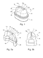
- la
figure 1 est une vue en perspective d'une buse pour une tête de distribution selon un mode de réalisation de l'invention ; - les
figures 2 sont des vues respectivement en coupe longitudinale (figure 2a ) et en coupe transversale (figure 2b ) de la buse de lafigure 1 ; - les
figures 3 sont des vues respectivement de dessous (figure 3a ) et de dessus (figure 3b ) de la buse de lafigure 1 ; - les
figures 4 sont des vues partielles d'un flacon équipé d'un système de distribution selon un mode de réalisation de l'invention, respectivement en coupe longitudinale (figure 4a ) et de côté (figure 4b ). - En relation avec les figures, on décrit un système de distribution comprenant une pompe 1 actionnée par une tête de distribution 2 de type bouton poussoir pour permettre la distribution d'un produit sous pression, par exemple sous la forme d'une noisette ou d'un flot continu.
- Pour ce faire, le système de distribution est monté sur un flacon 3 contenant le produit à distribuer sous pression. Dans un exemple d'application, le produit est une lotion, un gel ou une crème, pour un usage cosmétique ou pour des traitements pharmaceutiques.
- Le flacon 3 comprend un corps 4 surmonté par un col 5 et le système de distribution comprend une frette de fixation 6 sur laquelle la pompe 1 est montée, ladite frette étant associée au col 5 de sorte à mettre la pompe 1 en communication étanche avec le produit conditionné dans ledit corps.
- Sur la
figure 4a , la pompe 1 n'est pas coupée mais comprend classiquement un corps dans lequel sont disposés des moyens nécessaires pour la mise sous pression du produit à distribuer. Selon une réalisation particulière, la pompe 1 est de type sans reprise d'air en compensation du volume de produit distribué, de sorte à ne pas introduire de contaminant dans le flacon 3 et donc dans le produit conditionné. - L'invention n'est pas limitée à une structure de pompe 1 particulière, ni à un mode particulier de montage de la pompe 1 sur le flacon 3. En outre, la pompe 1 peut être alimentée en produit conditionné par l'intermédiaire d'un tube plongeur 7 disposé dans le flacon 3 ou par l'intermédiaire d'un piston d'amenée du produit qui est monté coulissant dans le corps 4 de sorte à pousser le produit dans la pompe 1.
- La pompe 1 comprend un tube d'amenée 8 du produit sous pression, ledit tube étant déplaçable réversiblement sur une course de distribution / aspiration du produit. Pour actionner ce déplacement, la tête de distribution 2 est montée sur la partie aval du tube d'amenée 8, ladite tête comprenant un corps 9 présentant un puits de montage 10 de ladite tête sur ledit tube d'amenée et un chemin de distribution du produit entre ledit puits et un orifice de distribution 11.
- Dans le mode de réalisation représenté, le chemin de distribution présente un passage aval 12 qui est équipé d'une buse 13 dans laquelle l'orifice de distribution 11 est formé. En particulier, la tête de distribution 2 présente un logement 14 dans lequel débouche le passage aval 12, la buse 13 comprenant une cheminée 15 de montage qui est fixée de façon étanche dans ledit logement, l'intérieur de ladite cheminée étant disposé sur le passage aval 12. En outre, la cheminée 15 est prolongée par un embout avant 16 formé d'une seule pièce, un conduit 17 d'alimentation de l'orifice de distribution 11 étant formé dans ledit embout.
- Ainsi, en fixant le puits de montage 10 sur le tube d'amenée 8, la distribution du produit est réalisée par appui sur le corps 9 pour actionner le déplacement dudit tube afin d'acheminer le produit conditionné depuis le tube d'amenée 8 vers l'orifice de distribution 11 par l'intermédiaire du passage aval 12, de la cheminée 15 et du conduit d'alimentation 17.
- Le système de distribution peut également être utilisé pour d'autres types de distribution. En particulier, le flacon 3 peut comprendre un corps 4 souple, la mise en pression du produit dans le tube d'amenée 8 s'effectuant alors par rapprochement des parois dudit flacon, sans mise en oeuvre d'une pompe.
- L'orifice de distribution 11 est formé entre deux parois longitudinales respectivement supérieure 11a et inférieure 11 b qui sont reliées de part et d'autre par respectivement une paroi latérale 11c, 11d. La dimension transversale des parois latérales 11c, 11d est inférieure à la dimension longitudinale des parois longitudinales 11a, 11b afin de distribuer le produit sous la forme d'une nappe qui présente une dimension longitudinale supérieure à sa dimension transversale.
- Dans le mode de réalisation représenté, les parois longitudinales 11a, 11 b et latérales 11c, 11d s'étendent dans l'embout 16 pour former le conduit d'alimentation 17, ledit conduit étant convergent vers l'orifice de distribution 11. Ainsi, le conduit d'alimentation 17 présente une section de géométrie identique à celle de l'orifice de distribution 11, le flux de produit sous pression étant poussé dans ledit conduit pour être distribué sous la forme d'une nappe dont la section est analogue à celle de l'orifice de distribution 11.
- Chacune des parois latérales 11c, 11d présente une saillie 18 qui s'étend entre les parois longitudinales 11a, 11b, au moins les parois 11 a-11 d de l'orifice de distribution 11 comprenant un agent antimicrobien pour le produit à distribuer. Ainsi, on combine une rigidification de la nappe au moyen des saillies latérales 18 avec une action contre la contamination du produit de ladite nappe par les bactéries, levures et moisissures.
- En particulier, on assure la décontamination du produit qui, entre deux distributions, est localisé au voisinage de l'orifice de distribution 11 et on empêche la pénétration des bactéries, levures et moisissures dans le flacon 3 par l'intermédiaire du chemin de distribution.
- De façon avantageuse, la surface extérieure 16a de l'embout avant 16 dans laquelle l'orifice de distribution 11 est formé peut également comprendre un agent antimicrobien. Ainsi, on empêche la contamination des souillures disposées sur cette surface 16a entre deux distributions, notamment par étalement dudit produit lors de sa récupération par le doigt de l'utilisatrice, assurant ainsi que le produit distribué ultérieurement ne soit pas contaminé par lesdites souillures.
- De même, le chemin de distribution et notamment le conduit d'alimentation 17 dans lequel du produit est immobilisé entre deux distributions peut comprendre un agent antimicrobien, notamment en présentant un volume inférieur à 0,1 mm3 afin de limiter la distance maximale séparant ledit agent du produit pour, par effet de surface sur un volume très faible de produit, s'assurer de la décontamination du produit contenu dans ledit volume.
- Les saillies 18 sont agencées pour éviter que la nappe ne roule sur elle-même lors de la distribution et pour augmenter la surface de contact entre le produit formant la nappe et l'agent antimicrobien. En particulier, les saillies 18 sont disposées à l'intérieur des bords latéraux de la nappe afin d'améliorer l'efficacité de l'action antimicrobienne en limitant la distance maximale entre le produit contenu dans lesdits bords et l'agent antimicrobien.
- En outre, la présence des saillies 18 permet d'augmenter la dimension transversale des parois latérales 11c, 11d et donc des bords latéraux de la nappe afin notamment de conserver un orifice de distribution 11 dont la section de passage est suffisante pour la dose de produit à distribuer, et ce sans altérer l'aspect et l'action de décontamination de la nappe.
- Selon la réalisation représentée, les parois longitudinales 11a, 11b sont convexes vers l'intérieur de l'orifice de distribution 11 de sorte à limiter la dimension transversale du passage central 19 qui est formé entre lesdites parois longitudinales. Ainsi, on garantie une bonne action contre les contaminations du produit distribué au travers du passage central 19, tout en augmentant la dimension transversale des bords de ladite nappe pour conserver une section de passage suffisante pour la dose à distribuer.
- En outre, chaque paroi latérale 11c, 11d présente une portion supérieure - respectivement inférieure - de liaison de la saillie 18 avec la paroi longitudinale supérieure 11a - respectivement inférieure 11b. Ainsi, dans l'orifice de distribution 11, on forme :
- un passage central 19 entre les parois longitudinales 11a, 11b, ledit passage central présentant une dimension transversale réduite pour favoriser l'action antimicrobienne sur le produit distribué au travers de lui ;
- quatre passages latéraux 20 entre les parois longitudinales 11a, 11 b et les saillies 18, lesdits passages latéraux présentant une dimension réduite pour favoriser l'action antimicrobienne sur le produit distribué au travers d'eux, tout en contribuant à l'augmentation de la section de l'orifice de distribution 11.
- Dans le mode de réalisation représenté, chaque portion des parois latérales 11c, 11d est arrondie pour former un passage latéral 20 en forme de lobe entre chacune des parois longitudinales 11a, 11b et une saillie 18.
- De façon avantageuse, la dimension transversale maximale de l'orifice de distribution 11 entre les parois longitudinales 11a, 11b est inférieure ou égale à 0,5 mm, c'est-à-dire que la distance maximale entre l'agent antimicrobien et le produit distribué par le passage central 19 est inférieure à 0,25 mm. De même, la dimension transversale maximale de l'orifice de distribution 11 entre les parois longitudinales 11a, 11 b et les saillies 18 peut être inférieure ou égale à 0,5 mm pour que la distance maximale entre l'agent microbien et le produit distribué par les passages latéraux 20 soit inférieure à 0,25 mm. Ainsi, par effet de surface sur un film très mince de produit, on s'assure de la décontamination du produit contenu dans l'orifice de distribution 11.
- Selon une réalisation avantageuse, au moins les parois 11a-11d de l'orifice de distribution 11 comprennent du cuivre métallique qui, de par ses propriétés microbiostatiques, empêche la prolifération voire élimine les contaminants en contact avec lesdites parois, et ce sans migration dans le produit d'un quelconque agent antimicrobien.
- De façon avantageuse, la buse 13 comprend du cuivre métallique, notamment en étant réalisée en cuivre métallique ou en matériau synthétique, par exemple de type polyoléfine, qui est métallisé et/ou chargé en cuivre métallique.
- Selon une autre réalisation, au moins les parois 11a-11d de l'orifice de distribution 11 sont réalisées à base d'un matériau contenant un agent antimicrobien, notamment un agent microbiostatique et/ou microbiocide, par exemple sur base organique tel que le Trichlosan (dénomination commerciale de la Sté Melcoplast) ou sur base argent.
Claims (15)
- Tête de distribution (2) pour un système de distribution d'un produit sous pression, ladite tête comprenant un corps (9) présentant un puits de montage (10) de ladite tête sur un tube d'amenée (8) du produit sous pression et un chemin de distribution du produit entre ledit puits et un orifice de distribution (11) dudit produit, ledit orifice de distribution étant formé entre deux parois longitudinales respectivement supérieure (11a) et inférieure (11b) qui sont reliées de part et d'autre par respectivement une paroi latérale (11c, 11d) dont la dimension transversale est inférieure à la dimension longitudinale des parois longitudinales (11a, 11b), au moins les parois (11a-11d) de l'orifice de distribution (11) comprenant un agent antimicrobien pour le produit à distribuer, ladite tête de distribution étant caractérisée en ce que chacune des parois latérales (11c, 11d) présente une saillie (18) qui s'étend entre les parois longitudinales (11 a, 11b).
- Tête de distribution (2) selon la revendication 1, caractérisée en ce que chaque paroi latérale (11c, 11d) présente une portion supérieure - respectivement inférieure - de liaison de la saillie (18) avec la paroi longitudinale supérieure (11a) - respectivement inférieure (11b), de sorte à former dans l'orifice de distribution (11) quatre passages latéraux (20) et un passage central (19).
- Tête de distribution (2) selon la revendication 2, caractérisée en ce que chaque portion est arrondie pour former un passage latéral (20) en forme de lobe entre chacune des parois longitudinales (11a, 11 b) et une saillie (18).
- Tête de distribution (2) selon l'une quelconque des revendications 1 à 3, caractérisée en ce que les parois longitudinales (11a, 11b) sont convexes vers l'intérieur de l'orifice de distribution (11).
- Tête de distribution (2) selon l'une quelconque des revendications 1 à 4, caractérisée en ce que la dimension transversale maximale de l'orifice de distribution (11) entre les parois longitudinales (11a, 11b) est inférieure ou égale à 0,5 mm.
- Tête de distribution (2) selon l'une quelconque des revendications 1 à 5, caractérisée en ce que la dimension transversale maximale de l'orifice de distribution (11) entre les parois longitudinales (11a, 11 b) et les saillies (18) est inférieure ou égale à 0,5 mm.
- Tête de distribution (2) selon l'une quelconque des revendications 1 à 6, caractérisée en ce qu'au moins les parois (11a-11d) de l'orifice de distribution (11) comprend du cuivre métallique.
- Tête de distribution (2) selon l'une quelconque des revendications 1 à 6, caractérisée en ce qu'au moins les parois (11a-11d) de l'orifice de distribution (11) sont réalisées à base d'un matériau contenant un agent antimicrobien.
- Tête de distribution (2) selon l'une quelconque des revendications 1 à 8, caractérisée en ce que le chemin de distribution présente un passage aval (12) qui est équipé d'une buse (13) dans laquelle l'orifice de distribution (11) est formé.
- Tête de distribution (2) selon la revendication 9, caractérisée en ce que la buse (13) comprend une cheminée (15) de montage sur le passage aval (12), ladite cheminée étant prolongée par un embout avant (16) dans lequel un conduit (17) d'alimentation de l'orifice de distribution (11) est formé.
- Tête de distribution (2) selon la revendication 10, caractérisée en ce que les parois longitudinales (11a, 11b) et/ou latérales (11c, 11d) s'étendent dans l'embout avant (16) pour former le conduit d'alimentation (17).
- Tête de distribution (2) selon la revendication 10 ou 11, caractérisée en ce que le conduit d'alimentation (17) est convergent vers l'orifice de distribution (11).
- Système de distribution d'un produit sous pression, ledit système comprenant une tête de distribution (2) selon l'une quelconque des revendications 1 à 12 et un tube (8) d'amenée du produit sous pression sur lequel le puits de montage (10) de ladite tête est fixé.
- Système de distribution selon la revendication 13, caractérisé en ce qu'il comprend une pompe (1) actionnée par la tête de distribution (2), ladite pompe comprenant le tube (8) d'amenée du produit sous pression.
- Flacon (3) contenant un produit à distribuer sous pression, ledit flacon comprenant un col (5) sur lequel un système de distribution selon la revendication 13 ou 14 est associé de sorte à mettre le tube d'amenée (8) en communication avec le produit pour permettre l'acheminement du produit depuis ledit tube d'amenée vers l'orifice de distribution (11).
Applications Claiming Priority (1)
| Application Number | Priority Date | Filing Date | Title |
|---|---|---|---|
| FR1258306A FR2994865B1 (fr) | 2012-09-05 | 2012-09-05 | Tete de distribution pour un systeme de distribution d’un produit sous pression |
Publications (2)
| Publication Number | Publication Date |
|---|---|
| EP2705904A1 EP2705904A1 (fr) | 2014-03-12 |
| EP2705904B1 true EP2705904B1 (fr) | 2015-08-12 |
Family
ID=47425018
Family Applications (1)
| Application Number | Title | Priority Date | Filing Date |
|---|---|---|---|
| EP13182088.8A Active EP2705904B1 (fr) | 2012-09-05 | 2013-08-28 | Tête de distribution pour un système de distribution d un produit sous pression |
Country Status (6)
| Country | Link |
|---|---|
| US (1) | US9381532B2 (fr) |
| EP (1) | EP2705904B1 (fr) |
| CN (1) | CN103662362B (fr) |
| BR (1) | BR102013022582B1 (fr) |
| ES (1) | ES2549965T3 (fr) |
| FR (1) | FR2994865B1 (fr) |
Families Citing this family (8)
| Publication number | Priority date | Publication date | Assignee | Title |
|---|---|---|---|---|
| GB2526799B (en) * | 2014-06-02 | 2017-09-13 | Bamford Nigel | Fluid restriction nozzle for hand washing |
| FR3023734B1 (fr) * | 2014-07-17 | 2021-11-05 | Albea Le Treport | Tete de distribution pour un systeme de distribution d'un produit |
| CN104084324A (zh) * | 2014-07-21 | 2014-10-08 | 何祺晃 | 一种扇形微雾头 |
| USD800555S1 (en) * | 2015-10-19 | 2017-10-24 | Coach, Inc. | Sprayer |
| US9968804B2 (en) * | 2016-01-14 | 2018-05-15 | Reliance Industries, Llc | Nozzle for retractable fall arrest |
| CN110420765B (zh) * | 2019-07-26 | 2021-06-25 | 九牧厨卫股份有限公司 | 一种清洁喷头组件和自清洁浴缸 |
| FR3110868B1 (fr) * | 2020-05-29 | 2022-08-12 | Albea Le Treport | Tete de distribution d’un produit fluide et flacon de produit fluide associe |
| US11679403B1 (en) | 2022-02-02 | 2023-06-20 | Ries Ries Inc | Travel dispenser for dispensing a fluid |
Family Cites Families (13)
| Publication number | Priority date | Publication date | Assignee | Title |
|---|---|---|---|---|
| US3178120A (en) * | 1962-08-08 | 1965-04-13 | Henry C Kappel | Two piece spray nozzle |
| US3415426A (en) * | 1966-05-16 | 1968-12-10 | Eaton Yale & Towne | Dispensing valve |
| US5154325A (en) * | 1991-01-09 | 1992-10-13 | Ryder International Corporation | Solution delivery nozzle and system with antimicrobial features |
| WO1992012063A1 (fr) * | 1991-01-11 | 1992-07-23 | The Gillette Company | Organe de commande pour reservoir sous pression |
| FR2693991B1 (fr) * | 1992-07-21 | 1994-11-25 | Oreal | Ensemble de distribution d'au moins un produit liquide ou pâteux, comportant un système de fermeture sans reprise d'air et procédé de conservation utilisant ledit ensemble. |
| EP0891712A1 (fr) * | 1993-12-20 | 1999-01-20 | Biopolymerix, Inc. | Distributeur de liquide destiné à des solutions stériles |
| FR2723618B1 (fr) * | 1994-08-11 | 1996-10-31 | Sofab | Pompe a membrane |
| US6293441B1 (en) * | 1998-09-11 | 2001-09-25 | Yoshino Kogyosho Co., Ltd. | Trigger type liquid spray container for operation in both upright and inverted positions |
| ES2161198B1 (es) * | 2000-05-16 | 2002-07-01 | Calmar Monturas Sa | Bomba con dispositivo de descompresion. |
| DE102005010173B4 (de) * | 2005-03-05 | 2006-11-16 | Aero Pump GmbH, Zerstäuberpumpen | Austrittshaube für ein Sprühgerät zum Versprühen einer hochviskosen Flüssigkeit |
| US7886941B2 (en) * | 2005-04-25 | 2011-02-15 | Meadwestvaco Calmar Inc. | Dispenser having air tight spout |
| US8136703B2 (en) * | 2006-04-21 | 2012-03-20 | Toko Yakuhin Kogyo Kabushiki Kaisha | Fluid container and airless fluid dispensing system |
| AU2011238914A1 (en) * | 2010-04-06 | 2012-11-29 | Reseal International Limited Partnership | Delivery system for dispensing metered volumes of pure or sterile flowable substances |
-
2012
- 2012-09-05 FR FR1258306A patent/FR2994865B1/fr not_active Expired - Fee Related
-
2013
- 2013-08-28 ES ES13182088.8T patent/ES2549965T3/es active Active
- 2013-08-28 EP EP13182088.8A patent/EP2705904B1/fr active Active
- 2013-09-04 BR BR102013022582-7A patent/BR102013022582B1/pt active IP Right Grant
- 2013-09-05 US US14/019,227 patent/US9381532B2/en active Active
- 2013-09-05 CN CN201310532688.3A patent/CN103662362B/zh active Active
Also Published As
| Publication number | Publication date |
|---|---|
| ES2549965T3 (es) | 2015-11-03 |
| FR2994865A1 (fr) | 2014-03-07 |
| FR2994865B1 (fr) | 2014-09-26 |
| US9381532B2 (en) | 2016-07-05 |
| CN103662362A (zh) | 2014-03-26 |
| BR102013022582B1 (pt) | 2020-09-15 |
| EP2705904A1 (fr) | 2014-03-12 |
| CN103662362B (zh) | 2018-10-12 |
| BR102013022582A2 (pt) | 2017-05-09 |
| US20140061251A1 (en) | 2014-03-06 |
Similar Documents
| Publication | Publication Date | Title |
|---|---|---|
| EP2705904B1 (fr) | Tête de distribution pour un système de distribution d un produit sous pression | |
| CA2731971C (fr) | Flacon de conditionnement de liquide a distribuer goutte a goutte a protection antibacterienne | |
| EP2780120B1 (fr) | Tête de distribution pour un système de distribution d'un produit sous pression | |
| EP2279798B1 (fr) | Bouton poussoir pour un système de distribution d'un produit sous pression | |
| FR2830519A1 (fr) | Dispositif de distribution de produit fluide a actionnement lateral | |
| EP3648900B1 (fr) | Dispositif de distribution de produit fluide. | |
| EP3034178B1 (fr) | Tête de distribution pour un système de distribution d'un produit | |
| EP2879966B1 (fr) | Tete de distribution de liquide goutte a goutte | |
| EP2974797B1 (fr) | Tête de distribution pour un système de distribution d'un produit | |
| EP3431188B1 (fr) | Tete de distribution de produit provenant d'un recipient | |
| EP2490646A1 (fr) | Tete de distribution pour dispositif de distribution de produit fluide. | |
| EP3129154B1 (fr) | Module de distribution d'un produit destiné à être monté sur un conduit d'amenée sous pression dudit produit | |
| EP3363544A1 (fr) | Systeme de distribution d'un produit fluide | |
| EP2907584A1 (fr) | Récipient comprenant un réservoir et un système de distribution de produit | |
| WO2004058413A1 (fr) | Organe de distribution de produit fluide et distributeur comprenant un tel organe |
Legal Events
| Date | Code | Title | Description |
|---|---|---|---|
| PUAI | Public reference made under article 153(3) epc to a published international application that has entered the european phase |
Free format text: ORIGINAL CODE: 0009012 |
|
| AK | Designated contracting states |
Kind code of ref document: A1 Designated state(s): AL AT BE BG CH CY CZ DE DK EE ES FI FR GB GR HR HU IE IS IT LI LT LU LV MC MK MT NL NO PL PT RO RS SE SI SK SM TR |
|
| AX | Request for extension of the european patent |
Extension state: BA ME |
|
| 17P | Request for examination filed |
Effective date: 20140903 |
|
| RBV | Designated contracting states (corrected) |
Designated state(s): AL AT BE BG CH CY CZ DE DK EE ES FI FR GB GR HR HU IE IS IT LI LT LU LV MC MK MT NL NO PL PT RO RS SE SI SK SM TR |
|
| GRAP | Despatch of communication of intention to grant a patent |
Free format text: ORIGINAL CODE: EPIDOSNIGR1 |
|
| INTG | Intention to grant announced |
Effective date: 20150220 |
|
| GRAS | Grant fee paid |
Free format text: ORIGINAL CODE: EPIDOSNIGR3 |
|
| GRAA | (expected) grant |
Free format text: ORIGINAL CODE: 0009210 |
|
| AK | Designated contracting states |
Kind code of ref document: B1 Designated state(s): AL AT BE BG CH CY CZ DE DK EE ES FI FR GB GR HR HU IE IS IT LI LT LU LV MC MK MT NL NO PL PT RO RS SE SI SK SM TR |
|
| REG | Reference to a national code |
Ref country code: GB Ref legal event code: FG4D Free format text: NOT ENGLISH |
|
| REG | Reference to a national code |
Ref country code: CH Ref legal event code: EP |
|
| REG | Reference to a national code |
Ref country code: AT Ref legal event code: REF Ref document number: 741632 Country of ref document: AT Kind code of ref document: T Effective date: 20150815 |
|
| REG | Reference to a national code |
Ref country code: FR Ref legal event code: PLFP Year of fee payment: 3 |
|
| REG | Reference to a national code |
Ref country code: IE Ref legal event code: FG4D Free format text: LANGUAGE OF EP DOCUMENT: FRENCH |
|
| REG | Reference to a national code |
Ref country code: DE Ref legal event code: R096 Ref document number: 602013002601 Country of ref document: DE |
|
| REG | Reference to a national code |
Ref country code: ES Ref legal event code: FG2A Ref document number: 2549965 Country of ref document: ES Kind code of ref document: T3 Effective date: 20151103 |
|
| REG | Reference to a national code |
Ref country code: LT Ref legal event code: MG4D |
|
| REG | Reference to a national code |
Ref country code: AT Ref legal event code: MK05 Ref document number: 741632 Country of ref document: AT Kind code of ref document: T Effective date: 20150812 |
|
| REG | Reference to a national code |
Ref country code: NL Ref legal event code: MP Effective date: 20150812 |
|
| PG25 | Lapsed in a contracting state [announced via postgrant information from national office to epo] |
Ref country code: FI Free format text: LAPSE BECAUSE OF FAILURE TO SUBMIT A TRANSLATION OF THE DESCRIPTION OR TO PAY THE FEE WITHIN THE PRESCRIBED TIME-LIMIT Effective date: 20150812 Ref country code: LT Free format text: LAPSE BECAUSE OF FAILURE TO SUBMIT A TRANSLATION OF THE DESCRIPTION OR TO PAY THE FEE WITHIN THE PRESCRIBED TIME-LIMIT Effective date: 20150812 Ref country code: NO Free format text: LAPSE BECAUSE OF FAILURE TO SUBMIT A TRANSLATION OF THE DESCRIPTION OR TO PAY THE FEE WITHIN THE PRESCRIBED TIME-LIMIT Effective date: 20151112 Ref country code: LV Free format text: LAPSE BECAUSE OF FAILURE TO SUBMIT A TRANSLATION OF THE DESCRIPTION OR TO PAY THE FEE WITHIN THE PRESCRIBED TIME-LIMIT Effective date: 20150812 Ref country code: GR Free format text: LAPSE BECAUSE OF FAILURE TO SUBMIT A TRANSLATION OF THE DESCRIPTION OR TO PAY THE FEE WITHIN THE PRESCRIBED TIME-LIMIT Effective date: 20151113 |
|
| PG25 | Lapsed in a contracting state [announced via postgrant information from national office to epo] |
Ref country code: IS Free format text: LAPSE BECAUSE OF FAILURE TO SUBMIT A TRANSLATION OF THE DESCRIPTION OR TO PAY THE FEE WITHIN THE PRESCRIBED TIME-LIMIT Effective date: 20151212 Ref country code: HR Free format text: LAPSE BECAUSE OF FAILURE TO SUBMIT A TRANSLATION OF THE DESCRIPTION OR TO PAY THE FEE WITHIN THE PRESCRIBED TIME-LIMIT Effective date: 20150812 Ref country code: RS Free format text: LAPSE BECAUSE OF FAILURE TO SUBMIT A TRANSLATION OF THE DESCRIPTION OR TO PAY THE FEE WITHIN THE PRESCRIBED TIME-LIMIT Effective date: 20150812 Ref country code: SE Free format text: LAPSE BECAUSE OF FAILURE TO SUBMIT A TRANSLATION OF THE DESCRIPTION OR TO PAY THE FEE WITHIN THE PRESCRIBED TIME-LIMIT Effective date: 20150812 Ref country code: AT Free format text: LAPSE BECAUSE OF FAILURE TO SUBMIT A TRANSLATION OF THE DESCRIPTION OR TO PAY THE FEE WITHIN THE PRESCRIBED TIME-LIMIT Effective date: 20150812 Ref country code: PT Free format text: LAPSE BECAUSE OF FAILURE TO SUBMIT A TRANSLATION OF THE DESCRIPTION OR TO PAY THE FEE WITHIN THE PRESCRIBED TIME-LIMIT Effective date: 20151214 Ref country code: PL Free format text: LAPSE BECAUSE OF FAILURE TO SUBMIT A TRANSLATION OF THE DESCRIPTION OR TO PAY THE FEE WITHIN THE PRESCRIBED TIME-LIMIT Effective date: 20150812 |
|
| PG25 | Lapsed in a contracting state [announced via postgrant information from national office to epo] |
Ref country code: NL Free format text: LAPSE BECAUSE OF FAILURE TO SUBMIT A TRANSLATION OF THE DESCRIPTION OR TO PAY THE FEE WITHIN THE PRESCRIBED TIME-LIMIT Effective date: 20150812 |
|
| PG25 | Lapsed in a contracting state [announced via postgrant information from national office to epo] |
Ref country code: EE Free format text: LAPSE BECAUSE OF FAILURE TO SUBMIT A TRANSLATION OF THE DESCRIPTION OR TO PAY THE FEE WITHIN THE PRESCRIBED TIME-LIMIT Effective date: 20150812 Ref country code: CZ Free format text: LAPSE BECAUSE OF FAILURE TO SUBMIT A TRANSLATION OF THE DESCRIPTION OR TO PAY THE FEE WITHIN THE PRESCRIBED TIME-LIMIT Effective date: 20150812 Ref country code: DK Free format text: LAPSE BECAUSE OF FAILURE TO SUBMIT A TRANSLATION OF THE DESCRIPTION OR TO PAY THE FEE WITHIN THE PRESCRIBED TIME-LIMIT Effective date: 20150812 Ref country code: SK Free format text: LAPSE BECAUSE OF FAILURE TO SUBMIT A TRANSLATION OF THE DESCRIPTION OR TO PAY THE FEE WITHIN THE PRESCRIBED TIME-LIMIT Effective date: 20150812 |
|
| REG | Reference to a national code |
Ref country code: DE Ref legal event code: R097 Ref document number: 602013002601 Country of ref document: DE |
|
| PG25 | Lapsed in a contracting state [announced via postgrant information from national office to epo] |
Ref country code: MC Free format text: LAPSE BECAUSE OF FAILURE TO SUBMIT A TRANSLATION OF THE DESCRIPTION OR TO PAY THE FEE WITHIN THE PRESCRIBED TIME-LIMIT Effective date: 20150812 Ref country code: RO Free format text: LAPSE BECAUSE OF FAILURE TO SUBMIT A TRANSLATION OF THE DESCRIPTION OR TO PAY THE FEE WITHIN THE PRESCRIBED TIME-LIMIT Effective date: 20150812 |
|
| REG | Reference to a national code |
Ref country code: IE Ref legal event code: MM4A |
|
| PLBE | No opposition filed within time limit |
Free format text: ORIGINAL CODE: 0009261 |
|
| STAA | Information on the status of an ep patent application or granted ep patent |
Free format text: STATUS: NO OPPOSITION FILED WITHIN TIME LIMIT |
|
| 26N | No opposition filed |
Effective date: 20160513 |
|
| PG25 | Lapsed in a contracting state [announced via postgrant information from national office to epo] |
Ref country code: IE Free format text: LAPSE BECAUSE OF NON-PAYMENT OF DUE FEES Effective date: 20150828 |
|
| REG | Reference to a national code |
Ref country code: FR Ref legal event code: PLFP Year of fee payment: 4 |
|
| PG25 | Lapsed in a contracting state [announced via postgrant information from national office to epo] |
Ref country code: SI Free format text: LAPSE BECAUSE OF FAILURE TO SUBMIT A TRANSLATION OF THE DESCRIPTION OR TO PAY THE FEE WITHIN THE PRESCRIBED TIME-LIMIT Effective date: 20150812 |
|
| PG25 | Lapsed in a contracting state [announced via postgrant information from national office to epo] |
Ref country code: MT Free format text: LAPSE BECAUSE OF FAILURE TO SUBMIT A TRANSLATION OF THE DESCRIPTION OR TO PAY THE FEE WITHIN THE PRESCRIBED TIME-LIMIT Effective date: 20150812 |
|
| REG | Reference to a national code |
Ref country code: CH Ref legal event code: PL |
|
| PG25 | Lapsed in a contracting state [announced via postgrant information from national office to epo] |
Ref country code: CH Free format text: LAPSE BECAUSE OF NON-PAYMENT OF DUE FEES Effective date: 20160831 Ref country code: LI Free format text: LAPSE BECAUSE OF NON-PAYMENT OF DUE FEES Effective date: 20160831 |
|
| PG25 | Lapsed in a contracting state [announced via postgrant information from national office to epo] |
Ref country code: BG Free format text: LAPSE BECAUSE OF FAILURE TO SUBMIT A TRANSLATION OF THE DESCRIPTION OR TO PAY THE FEE WITHIN THE PRESCRIBED TIME-LIMIT Effective date: 20150812 Ref country code: HU Free format text: LAPSE BECAUSE OF FAILURE TO SUBMIT A TRANSLATION OF THE DESCRIPTION OR TO PAY THE FEE WITHIN THE PRESCRIBED TIME-LIMIT; INVALID AB INITIO Effective date: 20130828 |
|
| PG25 | Lapsed in a contracting state [announced via postgrant information from national office to epo] |
Ref country code: CY Free format text: LAPSE BECAUSE OF FAILURE TO SUBMIT A TRANSLATION OF THE DESCRIPTION OR TO PAY THE FEE WITHIN THE PRESCRIBED TIME-LIMIT Effective date: 20150812 |
|
| PG25 | Lapsed in a contracting state [announced via postgrant information from national office to epo] |
Ref country code: BE Free format text: LAPSE BECAUSE OF NON-PAYMENT OF DUE FEES Effective date: 20150831 |
|
| REG | Reference to a national code |
Ref country code: FR Ref legal event code: PLFP Year of fee payment: 5 |
|
| PG25 | Lapsed in a contracting state [announced via postgrant information from national office to epo] |
Ref country code: LU Free format text: LAPSE BECAUSE OF NON-PAYMENT OF DUE FEES Effective date: 20150828 |
|
| GBPC | Gb: european patent ceased through non-payment of renewal fee |
Effective date: 20170828 |
|
| PG25 | Lapsed in a contracting state [announced via postgrant information from national office to epo] |
Ref country code: SM Free format text: LAPSE BECAUSE OF FAILURE TO SUBMIT A TRANSLATION OF THE DESCRIPTION OR TO PAY THE FEE WITHIN THE PRESCRIBED TIME-LIMIT Effective date: 20150812 |
|
| PG25 | Lapsed in a contracting state [announced via postgrant information from national office to epo] |
Ref country code: TR Free format text: LAPSE BECAUSE OF FAILURE TO SUBMIT A TRANSLATION OF THE DESCRIPTION OR TO PAY THE FEE WITHIN THE PRESCRIBED TIME-LIMIT Effective date: 20150812 Ref country code: MK Free format text: LAPSE BECAUSE OF FAILURE TO SUBMIT A TRANSLATION OF THE DESCRIPTION OR TO PAY THE FEE WITHIN THE PRESCRIBED TIME-LIMIT Effective date: 20150812 |
|
| PG25 | Lapsed in a contracting state [announced via postgrant information from national office to epo] |
Ref country code: GB Free format text: LAPSE BECAUSE OF NON-PAYMENT OF DUE FEES Effective date: 20170828 |
|
| REG | Reference to a national code |
Ref country code: FR Ref legal event code: PLFP Year of fee payment: 6 |
|
| PG25 | Lapsed in a contracting state [announced via postgrant information from national office to epo] |
Ref country code: AL Free format text: LAPSE BECAUSE OF FAILURE TO SUBMIT A TRANSLATION OF THE DESCRIPTION OR TO PAY THE FEE WITHIN THE PRESCRIBED TIME-LIMIT Effective date: 20150812 |
|
| PGFP | Annual fee paid to national office [announced via postgrant information from national office to epo] |
Ref country code: ES Payment date: 20250901 Year of fee payment: 13 |
|
| PGFP | Annual fee paid to national office [announced via postgrant information from national office to epo] |
Ref country code: DE Payment date: 20250827 Year of fee payment: 13 |
|
| PGFP | Annual fee paid to national office [announced via postgrant information from national office to epo] |
Ref country code: IT Payment date: 20250820 Year of fee payment: 13 |
|
| PGFP | Annual fee paid to national office [announced via postgrant information from national office to epo] |
Ref country code: FR Payment date: 20250825 Year of fee payment: 13 |