EP2705906A2 - Système ultrasonore, générateur d'ultrasons et procédé de fonctionnement de celui-ci - Google Patents
Système ultrasonore, générateur d'ultrasons et procédé de fonctionnement de celui-ci Download PDFInfo
- Publication number
- EP2705906A2 EP2705906A2 EP13181693.6A EP13181693A EP2705906A2 EP 2705906 A2 EP2705906 A2 EP 2705906A2 EP 13181693 A EP13181693 A EP 13181693A EP 2705906 A2 EP2705906 A2 EP 2705906A2
- Authority
- EP
- European Patent Office
- Prior art keywords
- frequency
- excitation
- ultrasonic
- phase difference
- ultrasonic generator
- Prior art date
- Legal status (The legal status is an assumption and is not a legal conclusion. Google has not performed a legal analysis and makes no representation as to the accuracy of the status listed.)
- Granted
Links
Images



Classifications
-
- B—PERFORMING OPERATIONS; TRANSPORTING
- B06—GENERATING OR TRANSMITTING MECHANICAL VIBRATIONS IN GENERAL
- B06B—METHODS OR APPARATUS FOR GENERATING OR TRANSMITTING MECHANICAL VIBRATIONS OF INFRASONIC, SONIC, OR ULTRASONIC FREQUENCY, e.g. FOR PERFORMING MECHANICAL WORK IN GENERAL
- B06B1/00—Methods or apparatus for generating mechanical vibrations of infrasonic, sonic, or ultrasonic frequency
- B06B1/02—Methods or apparatus for generating mechanical vibrations of infrasonic, sonic, or ultrasonic frequency making use of electrical energy
- B06B1/0207—Driving circuits
- B06B1/0223—Driving circuits for generating signals continuous in time
- B06B1/0238—Driving circuits for generating signals continuous in time of a single frequency, e.g. a sine-wave
- B06B1/0246—Driving circuits for generating signals continuous in time of a single frequency, e.g. a sine-wave with a feedback signal
- B06B1/0253—Driving circuits for generating signals continuous in time of a single frequency, e.g. a sine-wave with a feedback signal taken directly from the generator circuit
Definitions
- the present invention relates to a method according to the preamble of claim 1 for operating an ultrasonic generator for RF power supply of an ultrasonic transducer, in particular for ultrasonic welding or ultrasonic cleaning, which ultrasonic generator has at least one by means of an exciter signal with an excitation frequency electrically energizable resonant circuit, in electrical operative connection with is at least one electro-mechanical vibration system of the ultrasonic transducer whose impedance has a magnitude maximum in a parallel resonance of the oscillating system and a magnitude minimum in a series resonance of the oscillating system.
- the invention relates to an ultrasonic generator according to the preamble of claim 10 for RF energy supply of an ultrasonic transducer, in particular for ultrasonic welding or ultrasonic cleaning, with at least one by means of an exciter signal with an excitation frequency electrically energizable resonant circuit with at least one electro-mechanical vibration system of an ultrasonic transducer in electrical operative connection can be coupled, the impedance has a magnitude maximum in a parallel resonance of the oscillating system and a magnitude minimum in a series resonance of the oscillating system.
- the invention relates to an ultrasound system, which ultrasound system has at least one ultrasound generator of the type mentioned in operative connection with at least one ultrasound transducer.
- Generic objects are for example from the EP 0 662 356 B1 known.
- the cited document discloses in particular a method for operating a generator for RF power supply of an ultrasonic transducer and its operation in a specific resonance state. Thereby the phase angle between the current and the voltage at the output of the generator becomes measured and used for frequency control of the generator by a voltage proportional to the phase angle between current and voltage is generated, wherein in addition to the phase angle of the current, the voltage and / or the apparent or active power at the RF output of the generator digitally processed as an additional control variable and is associated with the phase angle to determine the desired resonant frequency of the generator.
- the resonant frequency mentioned is the frequency of the parallel resonance of the ultrasound transducer, for the detection of which a starting frequency above the paraliel resonance is selected and subsequently regulated to the current minimum in order then to operate the ultrasound transducer in the parallel resonance of the impedance curve.
- the invention has for its object to provide an alternative method for operating an ultrasonic generator and a correspondingly trained ultrasonic generator, which ensure a simpler and more cost-effective way to operate in a predetermined or predeterminable operating point with appropriate output power and vibration amplitude.
- a method for operating an ultrasound generator for RF energy supply of an ultrasound transducer, in particular for ultrasonic welding or ultrasound cleaning which ultrasound generator has at least one oscillatory circuit which can be electrically excited by means of an exciter signal with an excitation frequency, is in electrical operative connection with at least one electro-mechanical oscillating system of the ultrasound transducer stands, which oscillating system at a first (excitation) frequency a parallel resonance and at a second (excitation) frequency has a series resonance, which is expressed on the basis of a maximum or a minimum of the magnitude of the impedance of the oscillating system, characterized in that a) in the resonant circuit, preferably in front of a parallel throttle contained therein, at least when the oscillatory system oscillates at an initial excitation frequency, the phase difference between the current and the voltage of the exciter signal is determined and used to control the frequency of the ultrasound generator; b) in response to the determined phase difference at a phase difference ⁇ 0 °, the frequency of the initial
- first measuring means it is not necessary in the context of the present invention for the abovementioned first measuring means to be designed directly for generating and providing a (analog) phase difference signal. Rather, it is alternatively possible to calculate the phase difference from the measured values for current and voltage (digital).
- An ultrasound system has at least one ultrasound generator according to the invention in operative connection with at least one ultrasound transducer, which ultrasound transducer or its electro-mechanical vibration system has a parallel resonance and a series resonance in its impedance as a function of the excitation frequency.
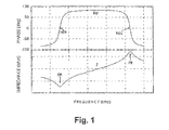
- the impedance of an ultrasonic transducer is a complex-valued variable and in FIG. 1 as a function of the frequency f separated by magnitude Z (actually
- Impedance is the ratio of complex alternating current to complex alternating current and includes for the skilled person the summary of two statements: It gives the ratio of the amplitude of sinusoidal alternating voltage to sinusoidal alternating current, and it indicates the phase shift between these two quantities. This phase shift is referred to herein as the "phase of the impedance" ( ⁇ ).
- the impedance points, in FIG. 1 Coming from lower frequencies, first an absolute minimum, which corresponds to the minimum impedance of a so-called series resonance SR of the oscillating system. At higher frequencies f, the impedance Z or its magnitude increases sharply, up to an absolute maximum in the so-called parallel resonance PR of the oscillatory system.
- the phase of the impedance or the phase difference ⁇ between (HF) current and (RF) voltage of the resonant circuit changes when negative voltage (-90 °) to positive occurs when connecting a voltage source when the series resonance SR is reached. + 90 °), and on reaching the parallel resonance PR back to -90 °.
- the phase angle is zero.
- the ultrasonic generator regulates the excitation frequency within a frequency band which is defined between the two zero crossings ND1 and ND2 of the phase difference.
- the said zero crossings ND1, ND2 coincide with respect to the associated frequency with the series resonance SR and the parallel resonance PR of the ultrasonic transducer.
- the phase angle between (HF) current and (HF) voltage is positive.
- the phase difference between current and voltage of the excitation signal is now determined in a first step in the resonant circuit of the ultrasonic generator, preferably in front of a parallel choke or inductor contained in the resonant circuit at least when the oscillatory system with an initial excitation frequency - If necessary in the form of a resulting phase difference signal - used for frequency control of the ultrasonic generator as a controlled variable.
- the current and the voltage are preferably measured in the resonant circuit, from whose temporal progressions the said phase difference can be determined, for example, digitally by means of a suitable processor.
- the initial excitation frequency is frequency-controlled such that the phase difference becomes substantially zero, with the oscillating system approaching its parallel resonance, which is an absolute maximum the impedance goes along.
- the corresponding frequency of the excitation signal is presently also called "start frequency" designated.
- the oscillating system or the ultrasonic transducer is then excited according to the invention at the starting frequency to ultrasonic vibrations.
- the excitation frequency is controlled such that the phase of the impedance is> 0 °.
- this means that for frequencies above the parallel resonance to search the start frequency, the frequency is lowered until ⁇ 0 ° (PR).
- the oscillating system In the context of the present invention, provision is made in this connection for the oscillating system to be operated following the method step d) at an operating point between parallel resonance and series resonance of the oscillating system ( ⁇ > 0 °). It is possible that the operating point is shifted in response to a user input or input, preferably in the direction of the series resonance for larger vibration amplitudes and / or for greater vibration power.
- the ultrasound generator determines the phase between (HF) current and (RF) voltage in the resonant circuit already at the start or during oscillation of the ultrasonic oscillating system and is thus able to determine whether the set initial Excitation frequency is in the right frequency range.
- the term "correct frequency range” is understood in particular to mean the frequency band ( ⁇ > 0 °) defined above. This allows the so-called Start frequency, which is predetermined by the resonance property of the ultrasonic transducer or the oscillating system to detect automatically readjust and optimize.
- the starting frequency is preferably determined by determining that frequency value at which the phase difference or the phase of the impedance vanishes in the parallel resonance or in the series resonance, ie the value zero accepts. This is most preferably done by means of a pre-scan at relatively low power, the initial excitation frequency then being adjusted substantially to the predetermined starting frequency of the excitation signal. In the optimum thus corresponds to the said starting frequency at which the ultrasonic generator tries to swing, just the frequency of the parallel resonance PR or the series resonance SR (see. FIG. 1 ). Depending on the power or amplitude specification, it can then be connected to the frequency of the series resonance SR or the parallel resonance PR (cf. FIG. 1 ). In principle, however, it is also possible, within the scope of a specific power or amplitude specification, to set a corresponding operating-point frequency approximated to the frequency of the series resonance or parallel resonance directly during the oscillation.
- An extremely preferred development of the method according to the invention provides that, preferably even before the oscillation system is excited, the distance between parallel resonance and series resonance of the oscillatory system is determined by changing the frequency of the exciter signal and determining the two frequency values at which the phase difference (cf. FIG. 1 ) disappears. This can in turn be done by means of a pre-scan at relatively low power.
- the mentioned (frequency) distance between parallel resonance and series resonance can be used when exciting the oscillating system as a rule basis for the frequency control of the ultrasonic generator.
- the ultrasound generator can thus detect whether the ultrasound vibration system is a rather narrowband or a relatively broadband system, which represents a measure of the quality of the system.
- the ultrasonic generator is accordingly able to optimally adapt its control characteristics to the system.
- control unit is understood to mean the frequency-related resolution between the series resonant station and the parallel resonant station. Due to the adapted control characteristic, the ultrasound generator can optimally find and adjust the desired operating point frequency in said frequency band, wherein the avoidable excitation of undesired secondary resonances of the ultrasound vibration system is reliably avoided.
- phase difference in addition to the mentioned phase difference, further physical variables can be measured in the resonant circuit and used as controlled variables for the frequency control.
- quantities HF current, reactive power and active power in the resonant circuit are mentioned in this context by way of example.
- At least one further property for example voltage and / or current of a primary, serving for generating the exciter signal electrical power supply signal measured and as a control variable for the frequency control and / or for a protective function is used to protect components of the ultrasonic generator.
- additional measurement data of a primary power supply unit (power supply) which supplies electrical power to an output stage in the ultrasonic generator can be added to the control in order to correct any fluctuation of the primary voltage of the power supply or to protect the output stage from overloading if the primary current is too high ( protection function).
- a corresponding development of the ultrasonic generator according to the invention provides in this context that in addition to the first measuring means, which are designed to determine the phase difference between the current and voltage of the excitation signal in the resonant circuit, additionally second measuring means are provided which are in electrical communication with the primary electrical power supply unit for generating the excitation signal stand. Said second measuring means are designed to determine at least one property, preferably voltage and / or current, of a primary electrical power supply signal generated by the power supply unit and to feed it back to the frequency control unit of the ultrasonic generator. Additionally or alternatively, the measured values provided by the second measuring means can also be used for the already mentioned protective function, which protective function serves to protect components of the ultrasonic generator from damage, for example the final stage.
- the frequency control unit of the ultrasonic generator according to the invention may be formed in the course of another development as an "intelligent" unit in the sense of a microprocessor, microcontroller, a digital signal processor or a FPGA (Field Programmable Gate Array) or in the form of another digital computer unit.
- the frequency control unit may further include a kind of "artificial intelligence", such as a neural network or an expert system, which preferably serves to provide predictions regarding the vibration behavior of the ultrasonic transducer or the ultrasonic vibration system in the course of modeling so positively influencing the control behavior, in particular to accelerate.
- this is a first device, preferably a software-based or firmware-based device, in particular automatically determining the distance between parallel resonance and series resonance of Having oscillation system by changing the frequency of the excitation signal.
- this preferably takes place on the basis of the frequency values vanishing phase difference between the current and voltage of the excitation signal and most preferably before the excitation of the oscillatory system by means of a pre-scan at relatively low power.
- the said distance can then be used as a control basis for the frequency control of the ultrasonic generator, in particular as an influencing variable in the setting of a fineness of the frequency control (control unit, see above) of the ultrasonic generator.
- a comparably designed second device may be provided for, in particular, automatic determination of the starting frequency. Preferably, this is also done on the basis of the frequency value with vanishing phase difference between current and voltage of the exciter signal in the parallel resonance and most preferably by means of a pre-scan at relatively low power. In this way, the initial excitation frequency is then substantially adjustable to the predetermined start frequency of the excitation signal.
- this further measuring means for determining at least one of the variables RF current, reactive power and active power in the resonant circuit, which measuring means are in electrical and signaling active connection with the frequency control unit of the ultrasonic generator to the above sizes as a further Use controlled variables for frequency control.
- the frequency control unit is constructed cascaded.
- PWM pulse width modulation
- PBM pulse width modulation
- FIG. 2 schematically shows a block diagram of an inventive ultrasound system, which is designated in its entirety by the reference numeral 1.
- the ultrasound system 1 comprises an ultrasound generator 2, to which an ultrasound transducer 3 having an electro-mechanical vibration system is connected in electrical operative connection, which in the present case is shown in the form of an equivalent circuit diagram.
- the ultrasonic transducer 3 generates according to the ultrasonic generator ultrasonic waves 4, which can be used for machining a workpiece 5, for example, for ultrasonic welding or ultrasonic cleaning, without the present invention would be limited thereto.
- the ultrasonic transducer 3 or the oscillating system has a frequency-dependent impedance behavior Z (f), which is shown here only symbolically (cf. FIG. 1 ).
- the ultrasonic transducer 3 With increasing (excitation) frequency f, the ultrasonic transducer 3 initially has a minimum of the impedance Z, followed by an impedance maximum.
- the impedance minimum coincides with the so-called series resonance SR of the ultrasonic transducer 3, while the impedance maximum coincides with the so-called parallel resonance PR of the ultrasonic transducer 3; whereupon on the basis of FIG. 1 has already been pointed out.
- the electrical or signal engineering coupling of the ultrasonic transducer 3 and the ultrasonic generator 2 takes place at reference numeral 2a, which designates an output or connection of the ultrasonic generator.
- the ultrasonic generator 2 comprises the following components: a (primary) power supply unit 2b; an amplifier output stage 2c which is supplied with electric power from the power supply unit 2b; a transformer 2d for transforming a voltage supplied from the power supply unit 2b to the required level; a matching network 2e with at least one inductance (L) or throttle 2f as part of a (total) resonant circuit 3 'in electrical or signal-related operative connection with the transformer 2d and first measuring means 2g, which are designed to measure physical quantities in the matching network 2e or the resonant circuit, wherein at least one first measuring means 2g1 for measuring the current and the voltage in the matching network 2e, ie formed in the resonant circuit 3 'in front of the inductor 2f, to determine therefrom the phase difference between (excitation
- first measuring means 2g2, 2g3 serve for measuring additional physical quantities within the matching network 2e or the oscillating circuit 3 ', such as reactive power or active power, which will also be discussed in more detail below.
- a frequency control unit 2h preferably has control means 2h1-2h3 arranged in cascade, which each use the measuring signals of the first measuring means 2g1-2g3 as a controlled variable for the frequency control.
- Drive means 2i act in accordance with the frequency control unit 2h on the output stage 2c, so that it provides the transformer 2d, the electrical energy of the supply unit 2b in the form of a specific, regulated frequency.
- the ultrasound generator 2 at 2j comprises further, second measuring means in signal-operative connection with the power supply unit 2b, which second measuring means 2j as the first measuring means 2g are in operative operative connection with the frequency control unit 2h.
- the second measuring means 2j are used to determine certain properties, such as voltage or current, of the energy supply unit 2b, so that they can also be used as a control variable for the frequency control.
- the measured properties of the energy supply unit 2b can also be used in the sense of a protective function for components of the ultrasonic generator 2, for example in order to protect the output stage 2c from overloading if the primary current (too high current intensity at the energy supply unit 2b) is too high.
- the frequency control unit 2h may be formed together with (functional constituent) parts of the first 2g and the second measuring means 2j in the form of a program-controlled or programmable digital processor unit 2k, which is operable by an operator of the ultrasound system 1 by means of external user inputs, the latter being in FIG. 2 was not explicitly shown for reasons of clarity.
- Such user input includes, for example, inputting a desired amplitude of vibration or desired ultrasound power.
- the measured values which are measured by the first measuring means 2g on the matching network 2e or on the oscillating circuit 3 ', give the frequency control unit 2h all measuring data which are required for determining and correcting the operating frequency to be output.
- measurement data supplied by the second measuring means 2j of the primary power or energy supply unit 2b can also be used, which primary power supply unit supplies the final stage 2c with electrical energy. If such further measured values are supplied to the frequency control unit 2h, any fluctuation in the primary voltage of the power supply unit 2b can be compensated. As has already been mentioned, it is additionally possible to protect the output stage 2c against overload when the primary current is too high.
- the output stage 2c which is driven by the drive unit 2i, gives the transformer 2d the electrical energy of the primary supply unit 2b in the form of a specific frequency (excitation frequency).
- the transformer 2d transforms the voltage supplied by the power supply unit 2b to the required level and applies this voltage to the oscillating circuit 3 '.
- the measurement network 2e / the resonant circuit 3 'or the inductance or parallel choke 2f contained there again receives new measurement data (by the first measuring means 2g) which the frequency control unit 2h needs in order to readjust the excitation frequency to the conditions.
- the conditions mentioned include, in particular, the actual load or vibration state of the ultrasonic transducer 3 or of the oscillating system, the specified operating specifications by an operator and further (physical) parameters of the ultrasound system, for example its heating during operation.
- the electrical energy passes through the output or terminal 2a in the form of the output Excitation frequency in the ultrasonic vibrator connected to the ultrasonic generator 2 (ultrasonic transducer 3), which converts the electrical excitation energy into mechanical vibrations, which is known in principle to those skilled in the art.
- the combination of matching network 2e and ultrasonic transducer 3 acts as a resonant circuit 3 ', which has already been pointed out several times.
- the matching network may also have at least one capacitance (C), which is known to the person skilled in the art and disclosed in US Pat FIG. 2 not shown.
- FIGS. 3 to 5 Preferred embodiments of the ultrasonic generator 2 in the region of the transformer 2d, the matching network 2e and the first measuring means 2g connected thereto will now be explained in greater detail.
- like reference numerals designate the same or equivalent elements.
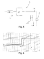
- FIG. 3 shows a block diagram of an embodiment in which in the matching network 2e of the ultrasonic generator 2 before the inductor 2f a current transformer or current sensor 2g1 is arranged, which generates a corresponding (current) measurement signal SM1 and at the in FIG. 3 not explicitly drawn frequency control unit 2h provides (dashed arrow in FIG. 3 ). Since the inductance 2f according to FIG. 3 is connected in parallel to the output or termination 2a of the ultrasonic generator 2, it is also referred to as a parallel throttle.
- FIG. 4 shows a development of the circuit arrangement FIG. 3 in which in each case one current transformer or current sensor 2g1 is arranged in front of the parallel throttle 2f and another 2g2 behind the parallel throttle 2f.
- the current transformer or current sensor 2g2 arranged behind the inductance 2f only measures the current share through the inductance 2f.
- the current can be calculated by the ultrasound transducer 3, for example by the processor unit 2k, so that in the frequency control unit 2h (cf. FIG. 2 ) in an advantageous manner then a pure active current signal is available for control purposes.
- FIG. 5 it is in a slight modification of the circuit arrangement FIG. 3 basically also possible to measure the current upstream of the transformer 2d by means of a correspondingly arranged current transformer or current sensor 2g ', which measures a corresponding measurement signal SM' at the frequency regulation unit 2h (cf. FIG. 2 ).
- a correspondingly arranged current transformer or current sensor 2g ' which measures a corresponding measurement signal SM' at the frequency regulation unit 2h (cf. FIG. 2 ).
- FIG. 6 shows signal waveforms for the phase signal of the voltage ⁇ U or fU and for the phase signal of the current ⁇ I and fI over the time t.
- the two signals ⁇ U / fU and ⁇ I / fI are obtained by a corresponding analog processing from the measurements of current and voltage.
- the mentioned preparation is carried out by the processor 2k (cf. FIG. 2 ) based on the corresponding measurement signals, in particular the current measurement signals SM1, SM2 or SM '( FIGS. 3 to 5 ).
- the processor 2k can calculate the phase or the phase difference and generate a corresponding phase difference signal.
- the said phase difference becomes zero when the ultrasonic transducer 3 (see. FIGS. 2 to 5 ) is excited at its parallel resonance or at its series resonance.
- phase signals according to FIG. 6 it is also possible to use the phase signals according to FIG. 6 to generate a proportional to the phase signals DC voltage and this the processor 2k (see. FIG. 2 ) on an ADC pin.
- this would disadvantageously be associated with a reduced measuring speed, a reduced measuring accuracy and an increased susceptibility to interference.
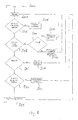
- FIG. 7 shows a flowchart of an embodiment of the inventive method for operating an ultrasonic generator, in particular of the ultrasonic generator 2 according to FIG. 2 , to the high frequency (RF) energy supply of an ultrasonic transducer, in particular of the ultrasonic transducer 3 according to FIG. 2
- the method preferably proceeds at the instigation of the processor 2k.
- step S100 for example by an operator operating the ultrasound system 1 or the ultrasound generator 2 according to FIG FIG. 2 starts up.
- step S102 a determination of the bandwidth of the ultrasound system takes place.
- this is to be understood as meaning that the (frequency) distance between parallel resonance PR and series resonance SR (cf. FIG. 1 . FIG. 2 ) of the connected ultrasonic transducer or oscillating system is determined.
- the system remains limited to this area in later operation, in order to avoid unwanted side resonances of the oscillatory system.
- the determination of the bandwidth takes place in such a way that the distance between the parallel resonance and the series resonance of the oscillating system is determined by changing the frequency of the excitation signal and determining the zero crossings of the phase difference signal, in particular by means of a preliminary scan with relatively low power.
- the zero crossings ND1, ND2 (cf. FIG. 1 ) of the phase difference or the associated phase difference signal can be determined, as described above with reference to FIG. 6 already discussed in principle.
- the frequencies of said zero crossings depend on the type of the connected ultrasound transducer or oscillating system and are essentially known after operation of the ultrasound generator following step S102.
- step S104 the adjustment of the control unit of the frequency control unit.
- This is understood to mean that, given a relatively small distance between the zero crossings or resonance points, ie a relatively steep profile of the impedance curve in the region between ND1 and ND2 (cf. FIG. 1 ) a relatively fine regulator is required, so that in the context of the present invention, a corresponding adjustment of the frequency control unit 2h (see. FIG. 2 ) he follows. If, on the other hand, the resonance points are relatively far apart, which corresponds to a flat course of the impedance curve in said region, a correspondingly coarser regulator can be used.
- step S106 the start frequency for exciting the vibration system is searched.
- step S108 a query is made as to whether the desired starting frequency has already been found. If the query is denied (-) in step S108, the process proceeds to step S106. If the queries are affirmative (+) in step 108, the oscillation system is then acted upon at the start frequency in step S110. Since the starting frequency - as stated - substantially coincides with the frequency of the parallel resonance of the oscillating system, the impedance of the oscillating system is according to FIG. 1 relatively high impedance, so that only little power is delivered and the amplitude of the mechanical vibration is small. It is desirable for reasons of reliability and durability of the system, when the first application of the vibration system takes place in its parallel resonance.
- step S112 the power is adjusted or increased according to user specification, in particular by increasing the applied voltage and / or current.
- step S114 in the course of a so-called frequency shifting, the excitation frequency is applied to the frequency of the series resonance SR (cf. FIG. 1 ), which, starting from the parallel resonance PR, is regularly associated with a reduction in the excitation frequency. This happens until the desired operating point of the ultrasound system is reached. This is equivalent to the fact that the ultrasound system delivers the desired output power or oscillation amplitude at the operating point.
- the corresponding values can be read by an operator on the ultrasound generator 2 (cf. FIG. 2 ) and form corresponding desired values or desired variables for the frequency control unit 2h.
- step S116 a query is made as to whether the desired operating point (control target value) has already been reached. If this query is answered in the negative (-), the process returns to step S114. If the answer is affirmative (+) in step S116, the set frequency becomes Maintaining step S118, and the ultrasound machine is operated at the selected operating point.
- step S118 the frequency is readjusted if other system parameters are changed, for example if the system heats up when the system heats up, which as a rule shifts the operating point down to lower frequencies left in FIG. 1 ).
- Lowering the frequency associated with step S114 includes not lowering the frequency to below the series resonant frequency to avoid exciting undesirable side resonances of the vibratory system.
- step S120 ends with step S120 following step S118.
- the starting frequency is also possible to set the starting frequency to the determined frequency of the series resonance and then to increase the frequency, or to directly consult a frequency in the working range (phase greater than zero).
- This double arrow symbolizes a preferred further embodiment of the processor or the processor unit 2 k, which can be designed as an "intelligent" unit (artificial intelligence) or in the form of an expert system, in order to obtain additional information concerning the vibration or modeling by modeling.
- the processor unit 2k may be designed to record and evaluate certain measured behavioral parameters of the ultrasound transducer and to derive therefrom assumptions for later reoperation of the ultrasound system 1. In particular, such predictions can serve to predetermine the starting frequency mentioned above as precisely as possible in order to shorten the initial adjustment of the ultrasound generator 3.
- FIG. 8 shows with reference to a flowchart, another embodiment of the inventive method for operating an ultrasonic generator, in particular of the ultrasonic generator 2 according to FIG. 2 for the high-frequency (HF) energy supply of an ultrasonic transducer, in particular of the ultrasonic transducer 3 according to FIG. 2
- the method preferably proceeds at the instigation of the processor 2k.
- step S200 begins with step S200, for example by an operator operating the ultrasound system 1 or the ultrasound generator 2, respectively FIG. 2 starts up.
- step S202 is followed by a measuring step at reference symbol S202 in order to determine the physical or electrical parameters required for the regulation of the system, in particular using the already described with reference to FIG. 2 explained measuring means 2g, 2j.
- Measured in this context in particular the RF current and the RF voltage, from which the RF power (by product formation) and the phase, ie the relative phase position or phase difference between the RF current and RF voltage can be determined.
- phase listed there again denotes the phase of the impedance.
- frequency change is case-specific, as explained in detail above, as well as the “frequency control”.
- Power limitation means a specification of the maximum permissible power by the device or by the user.
- Actual value and “Reference value” stand for corresponding values for power or amplitude - depending on the application. For example, for ultrasonic cleaning applications, performance may be the critical parameter, while welding applications tend to rely on the amplitude of the vibration.
- step S204 a query is made as to whether the measured HF current is above a predetermined threshold value "overcurrent threshold”. If the answer is affirmative in S204, the generator is turned off to protect the system in the course of a protection function (step S206).
- step S204 a query is made in a subsequent step S208 as to whether the power effective in the vibration system is greater than a predetermined maximum power. If the query in step S208 is answered in the affirmative, a further query is made in step S210 as to whether the phase difference between the HF current and the HF voltage is less than zero. If the query is answered in the negative in step S210, a control over the frequency is made in step S212 in connection with a power limitation for finding the parallel resonance, and the method returns to step S202. If the query in step S210 is affirmative, a PWM control for power reduction and a phase control to achieve a phase difference of 0 ° (parallel resonance) is performed in step S214.
- the system has a particularly high impedance, which is why the required power reduction takes place via the pulse width adjustment of the exciter signal (before the adaptation, the exciter signal can have an on-off ratio of 1 to 1, correspondingly less after the power has been reduced.)
- the method then also returns back to step S202.
- step S208 a further query is made in step S216 as to whether the phase difference between the HF current and the HF voltage is less than zero. If this query is answered in the affirmative, a frequency change takes place in step S218. Subsequently, the process returns to step S202.
- step S220 a further query is made in step S220 as to whether the phase difference between the HF current and the HF voltage is zero and whether an actual value of the power / amplitude is smaller than a corresponding desired value. These values can be specified by the user or they are permanently set in the device. If the answer is affirmative in step S220, frequency control is performed to zero phase difference in step S222, and the process returns to step S202.
- step S220 If the query is denied in step S220, frequency control is performed to a power / amplitude setpoint in step S224, and the method returns to step S202.
- phase difference between HF current and HF voltage is equivalent to a consideration of the phase of Complex impedance of the repeatedly addressed resonant circuit resulting from the generator's own matching network and the connected ultrasonic transducer.
Landscapes
- Engineering & Computer Science (AREA)
- Mechanical Engineering (AREA)
- Apparatuses For Generation Of Mechanical Vibrations (AREA)
Applications Claiming Priority (1)
| Application Number | Priority Date | Filing Date | Title |
|---|---|---|---|
| DE102012215993.2A DE102012215993A1 (de) | 2012-09-10 | 2012-09-10 | Ultraschallsystem, Ultraschallgenerator und Verfahren zum Betreiben eines solchen |
Publications (3)
| Publication Number | Publication Date |
|---|---|
| EP2705906A2 true EP2705906A2 (fr) | 2014-03-12 |
| EP2705906A3 EP2705906A3 (fr) | 2017-12-13 |
| EP2705906B1 EP2705906B1 (fr) | 2020-06-03 |
Family
ID=49080676
Family Applications (1)
| Application Number | Title | Priority Date | Filing Date |
|---|---|---|---|
| EP13181693.6A Active EP2705906B1 (fr) | 2012-09-10 | 2013-08-26 | Système ultrasonore, générateur d'ultrasons et procédé de fonctionnement de celui-ci |
Country Status (2)
| Country | Link |
|---|---|
| EP (1) | EP2705906B1 (fr) |
| DE (1) | DE102012215993A1 (fr) |
Cited By (15)
| Publication number | Priority date | Publication date | Assignee | Title |
|---|---|---|---|---|
| CN108471242A (zh) * | 2018-03-13 | 2018-08-31 | 深圳市大七易科技有限公司 | 一种超声波焊接电源频率的扫频追频控制方法 |
| CN109075760A (zh) * | 2016-04-25 | 2018-12-21 | 南洋理工大学 | 超声装置,其形成方法及其控制方法 |
| CN110337596A (zh) * | 2017-02-27 | 2019-10-15 | 罗伯特·博世有限公司 | 具有用于借助声波执行环境检测的传感器的传感器设备 |
| CN113899947A (zh) * | 2021-08-24 | 2022-01-07 | 深圳圣诺医疗设备股份有限公司 | 一种超声换能器获取谐振频率及校准功率方法和系统 |
| CN114204923A (zh) * | 2021-12-16 | 2022-03-18 | 珠海格力电器股份有限公司 | Pwm信号的处理方法、装置及计算机可读存储介质 |
| CN114290685A (zh) * | 2021-12-30 | 2022-04-08 | 上海骄成超声波技术股份有限公司 | 一种超声波发生器和超声波系统 |
| CN114818807A (zh) * | 2022-04-25 | 2022-07-29 | 广东利元亨智能装备股份有限公司 | 频率追踪方法、装置、电子设备及计算机可读存储介质 |
| WO2022174661A1 (fr) * | 2021-02-20 | 2022-08-25 | 山东骏腾医疗科技有限公司 | Procédé et dispositif de traitement de tissu pathologique rapide par ultrasons |
| CN115040200A (zh) * | 2022-05-20 | 2022-09-13 | 以诺康医疗科技(苏州)有限公司 | 超声手术工具、其频率跟踪方法、其目标相位差确定方法及超声波换能器等效电路 |
| CN115742319A (zh) * | 2022-02-18 | 2023-03-07 | 东莞市佳源达科技有限公司 | 一种加快它激式超声波发生器的追频速度的方法 |
| CN116033972A (zh) * | 2020-08-31 | 2023-04-28 | 西门子股份公司 | 振动系统的谐振方法、转换器、激励单元及振动系统 |
| CN116676167A (zh) * | 2023-06-20 | 2023-09-01 | 深圳汇芯生物医疗科技有限公司 | 用于分离提纯外泌体的过滤设备 |
| CN117982203A (zh) * | 2024-04-02 | 2024-05-07 | 北京速迈医疗科技有限公司 | 超声系统的振幅控制方法、装置、计算机设备及存储介质 |
| CN118161768A (zh) * | 2024-02-02 | 2024-06-11 | 沈阳长江源科技发展有限公司 | 球面超声换能单管驱动装置、方法、控制系统及治疗设备 |
| CN118891111A (zh) * | 2022-03-15 | 2024-11-01 | 海尔曼超声波技术两合有限公司 | 具有改进的幅度调节的超声声学振动发生系统 |
Families Citing this family (2)
| Publication number | Priority date | Publication date | Assignee | Title |
|---|---|---|---|---|
| DE102012217318A1 (de) | 2012-09-25 | 2014-05-28 | Weber Ultrasonics Gmbh | Kommunikationseinrichtung für ein Ultraschallgerät und Verfahren zum Betreiben eines solchen |
| US20240425216A1 (en) | 2021-11-19 | 2024-12-26 | Tetra Laval Holdings & Finance S.A. | Sealing device for a packaging machine, packaging machine having a sealing device and method of operating a sealing device |
Citations (3)
| Publication number | Priority date | Publication date | Assignee | Title |
|---|---|---|---|---|
| EP0662356B1 (fr) | 1994-01-05 | 1999-04-07 | BRANSON ULTRASCHALL Niederlassung der EMERSON TECHNOLOGIES GmbH & CO. | Procédé et dispositif d'entraínement d'un générateur pour l'alimentation d'énergie HF d'un transducteur à ultrason |
| US7475801B2 (en) | 2005-12-29 | 2009-01-13 | Dukane Corporation | Systems for providing controlled power to ultrasonic welding probes |
| DE102010004468A1 (de) | 2010-01-13 | 2011-07-14 | Maschinenfabrik Spaichingen GmbH, 78549 | Verfahren und Vorrichtung zur Ultraschallbearbeitung |
Family Cites Families (4)
| Publication number | Priority date | Publication date | Assignee | Title |
|---|---|---|---|---|
| DE3625149A1 (de) * | 1986-07-25 | 1988-02-04 | Herbert Dipl Ing Gaessler | Verfahren zur phasengesteuerten leistungs- und frequenzregelung eines ultraschallwandlers sowie vorrichtung zur durchfuehrung des verfahrens |
| US5431664A (en) * | 1994-04-28 | 1995-07-11 | Alcon Laboratories, Inc. | Method of tuning ultrasonic devices |
| FR2740572B1 (fr) * | 1995-10-27 | 1997-12-26 | Lorraine Laminage | Procede et dispositif de pilotage d'actionneurs a ultra-sons de puissance |
| US8798950B2 (en) * | 2010-08-20 | 2014-08-05 | Bio-Rad Laboratories, Inc. | System and method for ultrasonic transducer control |
-
2012
- 2012-09-10 DE DE102012215993.2A patent/DE102012215993A1/de not_active Ceased
-
2013
- 2013-08-26 EP EP13181693.6A patent/EP2705906B1/fr active Active
Patent Citations (3)
| Publication number | Priority date | Publication date | Assignee | Title |
|---|---|---|---|---|
| EP0662356B1 (fr) | 1994-01-05 | 1999-04-07 | BRANSON ULTRASCHALL Niederlassung der EMERSON TECHNOLOGIES GmbH & CO. | Procédé et dispositif d'entraínement d'un générateur pour l'alimentation d'énergie HF d'un transducteur à ultrason |
| US7475801B2 (en) | 2005-12-29 | 2009-01-13 | Dukane Corporation | Systems for providing controlled power to ultrasonic welding probes |
| DE102010004468A1 (de) | 2010-01-13 | 2011-07-14 | Maschinenfabrik Spaichingen GmbH, 78549 | Verfahren und Vorrichtung zur Ultraschallbearbeitung |
Cited By (20)
| Publication number | Priority date | Publication date | Assignee | Title |
|---|---|---|---|---|
| CN109075760A (zh) * | 2016-04-25 | 2018-12-21 | 南洋理工大学 | 超声装置,其形成方法及其控制方法 |
| CN109075760B (zh) * | 2016-04-25 | 2024-04-02 | 南洋理工大学 | 超声装置,其形成方法及其控制方法 |
| CN110337596A (zh) * | 2017-02-27 | 2019-10-15 | 罗伯特·博世有限公司 | 具有用于借助声波执行环境检测的传感器的传感器设备 |
| CN110337596B (zh) * | 2017-02-27 | 2024-03-12 | 罗伯特·博世有限公司 | 具有用于借助声波执行环境检测的传感器的传感器设备 |
| CN108471242A (zh) * | 2018-03-13 | 2018-08-31 | 深圳市大七易科技有限公司 | 一种超声波焊接电源频率的扫频追频控制方法 |
| CN116033972A (zh) * | 2020-08-31 | 2023-04-28 | 西门子股份公司 | 振动系统的谐振方法、转换器、激励单元及振动系统 |
| WO2022174661A1 (fr) * | 2021-02-20 | 2022-08-25 | 山东骏腾医疗科技有限公司 | Procédé et dispositif de traitement de tissu pathologique rapide par ultrasons |
| CN113899947B (zh) * | 2021-08-24 | 2024-03-26 | 深圳圣诺医疗设备股份有限公司 | 一种超声换能器获取谐振频率及校准功率方法和系统 |
| CN113899947A (zh) * | 2021-08-24 | 2022-01-07 | 深圳圣诺医疗设备股份有限公司 | 一种超声换能器获取谐振频率及校准功率方法和系统 |
| CN114204923A (zh) * | 2021-12-16 | 2022-03-18 | 珠海格力电器股份有限公司 | Pwm信号的处理方法、装置及计算机可读存储介质 |
| CN114290685B (zh) * | 2021-12-30 | 2024-02-06 | 上海骄成超声波技术股份有限公司 | 一种超声波发生器和超声波系统 |
| CN114290685A (zh) * | 2021-12-30 | 2022-04-08 | 上海骄成超声波技术股份有限公司 | 一种超声波发生器和超声波系统 |
| CN115742319A (zh) * | 2022-02-18 | 2023-03-07 | 东莞市佳源达科技有限公司 | 一种加快它激式超声波发生器的追频速度的方法 |
| CN118891111A (zh) * | 2022-03-15 | 2024-11-01 | 海尔曼超声波技术两合有限公司 | 具有改进的幅度调节的超声声学振动发生系统 |
| CN114818807A (zh) * | 2022-04-25 | 2022-07-29 | 广东利元亨智能装备股份有限公司 | 频率追踪方法、装置、电子设备及计算机可读存储介质 |
| CN115040200A (zh) * | 2022-05-20 | 2022-09-13 | 以诺康医疗科技(苏州)有限公司 | 超声手术工具、其频率跟踪方法、其目标相位差确定方法及超声波换能器等效电路 |
| CN115040200B (zh) * | 2022-05-20 | 2023-11-03 | 以诺康医疗科技(苏州)有限公司 | 超声手术工具、其频率跟踪方法、其目标相位差确定方法及超声波换能器等效电路 |
| CN116676167A (zh) * | 2023-06-20 | 2023-09-01 | 深圳汇芯生物医疗科技有限公司 | 用于分离提纯外泌体的过滤设备 |
| CN118161768A (zh) * | 2024-02-02 | 2024-06-11 | 沈阳长江源科技发展有限公司 | 球面超声换能单管驱动装置、方法、控制系统及治疗设备 |
| CN117982203A (zh) * | 2024-04-02 | 2024-05-07 | 北京速迈医疗科技有限公司 | 超声系统的振幅控制方法、装置、计算机设备及存储介质 |
Also Published As
| Publication number | Publication date |
|---|---|
| DE102012215993A1 (de) | 2014-03-13 |
| EP2705906A3 (fr) | 2017-12-13 |
| EP2705906B1 (fr) | 2020-06-03 |
Similar Documents
| Publication | Publication Date | Title |
|---|---|---|
| EP2705906B1 (fr) | Système ultrasonore, générateur d'ultrasons et procédé de fonctionnement de celui-ci | |
| DE69616667T2 (de) | RF-Anpassung Detektorschaltung mit doppeltem Richtkoppler | |
| EP1258978B1 (fr) | Système d'alimentation en courant | |
| DE69827659T2 (de) | Steuerungsmethode für ein phakoemulgatorhandstück | |
| DE69711691T2 (de) | Vorrichtung und verfahren zur anpassung einer last an eine quelle | |
| DE69723649T2 (de) | Verfahren und gerät zur steuerung der reaktiven impedanzen eines, zwischen einer rf quelle und einem rf plasmareaktor geschalteten anpassungsschaltkreises | |
| DE69728793T2 (de) | Frequenz- und leistungsregelunganordnung mit doppelkreis | |
| EP2737516B1 (fr) | Procédé et dispositif de protection de composants passifs connectés à un générateur haute fréquence | |
| DE102016007404B4 (de) | Servosteuervorrichtung mit Funktion zur Online-Optimierung der Regelungsverstärkung unter Verwendung einer Bewertungsfunktion | |
| DE3331896A1 (de) | Leistungsgenerator fuer einen ultraschallwandler | |
| DE10306347A1 (de) | Leistungszufuhrregeleinheit | |
| DE102021201937A1 (de) | Verfahren zur Impedanzanpassung, Impedanzanpassungsanordnung und Plasmasystem | |
| DE102010004649A1 (de) | Hochfrequenz (HF)-Spannungs-Versorgungssystem und Verfahren zur Versorgung eines Mulipolmassenspektrometers mit der Erzeugung eines Mulipolfeldes verwendeten HF_Wechselspannung und Teile davon | |
| EP2892660B1 (fr) | Procédé et système de circuit permettant de déterminer une zone de travail d'un ensemble convertisseur/booster/sonotrode à ultrasons | |
| DE112018001155T5 (de) | Magnetfelderzeugungsschaltung | |
| DE102020112851A1 (de) | Steuergerät für eine elektrische Antriebseinheit eines ophthalmochirurgischen Handstücks und Verfahren zu dessen Betrieb, ophthalmochirurgische Vorrichtung und System | |
| EP2838179B1 (fr) | Dispositif et procédé de transmission sans fil d'énergie | |
| EP3606677B1 (fr) | Machine d'usinage par ultrasons équipée de deux sonotrodes et procédé pour faire fonctionner une telle machine | |
| DE3783490T2 (de) | Anordnungen hoher leistung. | |
| WO2016141965A1 (fr) | Oscillateur et commutateur de proximité inductif | |
| DE4230491C2 (de) | Steuerschaltkreis für einen Ultraschallgenerator | |
| WO2024227892A1 (fr) | Dispositif de commande pour commander un système d'alimentation de traitement au plasma, système d'alimentation de traitement au plasma comprenant un tel dispositif de commande et procédé pour faire fonctionner un dispositif de commande | |
| WO2024256588A1 (fr) | Système d'alimentation pour processus à plasma, en particulier pour des processus à plasma pulsé, et procédé de fonctionnement d'un tel système d'alimentation pour processus à plasma | |
| DE102005030777B4 (de) | Verfahren und Schaltungsanordnung zum Betreiben eines Ultraschall-Schwingers | |
| DE69820262T2 (de) | Verfahren und vorrichtung zur steuerung der schalter in einem steuersystem mit variabeler struktur und steuerbarer frequenz |
Legal Events
| Date | Code | Title | Description |
|---|---|---|---|
| PUAI | Public reference made under article 153(3) epc to a published international application that has entered the european phase |
Free format text: ORIGINAL CODE: 0009012 |
|
| AK | Designated contracting states |
Kind code of ref document: A2 Designated state(s): AL AT BE BG CH CY CZ DE DK EE ES FI FR GB GR HR HU IE IS IT LI LT LU LV MC MK MT NL NO PL PT RO RS SE SI SK SM TR |
|
| AX | Request for extension of the european patent |
Extension state: BA ME |
|
| PUAL | Search report despatched |
Free format text: ORIGINAL CODE: 0009013 |
|
| AK | Designated contracting states |
Kind code of ref document: A3 Designated state(s): AL AT BE BG CH CY CZ DE DK EE ES FI FR GB GR HR HU IE IS IT LI LT LU LV MC MK MT NL NO PL PT RO RS SE SI SK SM TR |
|
| AX | Request for extension of the european patent |
Extension state: BA ME |
|
| RIC1 | Information provided on ipc code assigned before grant |
Ipc: B06B 1/02 20060101AFI20171106BHEP |
|
| STAA | Information on the status of an ep patent application or granted ep patent |
Free format text: STATUS: REQUEST FOR EXAMINATION WAS MADE |
|
| 17P | Request for examination filed |
Effective date: 20180612 |
|
| RBV | Designated contracting states (corrected) |
Designated state(s): AL AT BE BG CH CY CZ DE DK EE ES FI FR GB GR HR HU IE IS IT LI LT LU LV MC MK MT NL NO PL PT RO RS SE SI SK SM TR |
|
| RAP1 | Party data changed (applicant data changed or rights of an application transferred) |
Owner name: WEBER ULTRASONICS AG |
|
| GRAP | Despatch of communication of intention to grant a patent |
Free format text: ORIGINAL CODE: EPIDOSNIGR1 |
|
| STAA | Information on the status of an ep patent application or granted ep patent |
Free format text: STATUS: GRANT OF PATENT IS INTENDED |
|
| INTG | Intention to grant announced |
Effective date: 20200102 |
|
| GRAS | Grant fee paid |
Free format text: ORIGINAL CODE: EPIDOSNIGR3 |
|
| GRAA | (expected) grant |
Free format text: ORIGINAL CODE: 0009210 |
|
| STAA | Information on the status of an ep patent application or granted ep patent |
Free format text: STATUS: THE PATENT HAS BEEN GRANTED |
|
| AK | Designated contracting states |
Kind code of ref document: B1 Designated state(s): AL AT BE BG CH CY CZ DE DK EE ES FI FR GB GR HR HU IE IS IT LI LT LU LV MC MK MT NL NO PL PT RO RS SE SI SK SM TR |
|
| REG | Reference to a national code |
Ref country code: GB Ref legal event code: FG4D Free format text: NOT ENGLISH |
|
| REG | Reference to a national code |
Ref country code: CH Ref legal event code: EP Ref country code: AT Ref legal event code: REF Ref document number: 1276488 Country of ref document: AT Kind code of ref document: T Effective date: 20200615 |
|
| REG | Reference to a national code |
Ref country code: DE Ref legal event code: R096 Ref document number: 502013014753 Country of ref document: DE |
|
| REG | Reference to a national code |
Ref country code: CH Ref legal event code: NV Representative=s name: VALIPAT S.A. C/O BOVARD SA NEUCHATEL, CH |
|
| REG | Reference to a national code |
Ref country code: LT Ref legal event code: MG4D |
|
| PG25 | Lapsed in a contracting state [announced via postgrant information from national office to epo] |
Ref country code: LT Free format text: LAPSE BECAUSE OF FAILURE TO SUBMIT A TRANSLATION OF THE DESCRIPTION OR TO PAY THE FEE WITHIN THE PRESCRIBED TIME-LIMIT Effective date: 20200603 Ref country code: NO Free format text: LAPSE BECAUSE OF FAILURE TO SUBMIT A TRANSLATION OF THE DESCRIPTION OR TO PAY THE FEE WITHIN THE PRESCRIBED TIME-LIMIT Effective date: 20200903 Ref country code: SE Free format text: LAPSE BECAUSE OF FAILURE TO SUBMIT A TRANSLATION OF THE DESCRIPTION OR TO PAY THE FEE WITHIN THE PRESCRIBED TIME-LIMIT Effective date: 20200603 Ref country code: GR Free format text: LAPSE BECAUSE OF FAILURE TO SUBMIT A TRANSLATION OF THE DESCRIPTION OR TO PAY THE FEE WITHIN THE PRESCRIBED TIME-LIMIT Effective date: 20200904 Ref country code: FI Free format text: LAPSE BECAUSE OF FAILURE TO SUBMIT A TRANSLATION OF THE DESCRIPTION OR TO PAY THE FEE WITHIN THE PRESCRIBED TIME-LIMIT Effective date: 20200603 |
|
| REG | Reference to a national code |
Ref country code: NL Ref legal event code: MP Effective date: 20200603 |
|
| PG25 | Lapsed in a contracting state [announced via postgrant information from national office to epo] |
Ref country code: RS Free format text: LAPSE BECAUSE OF FAILURE TO SUBMIT A TRANSLATION OF THE DESCRIPTION OR TO PAY THE FEE WITHIN THE PRESCRIBED TIME-LIMIT Effective date: 20200603 Ref country code: HR Free format text: LAPSE BECAUSE OF FAILURE TO SUBMIT A TRANSLATION OF THE DESCRIPTION OR TO PAY THE FEE WITHIN THE PRESCRIBED TIME-LIMIT Effective date: 20200603 Ref country code: LV Free format text: LAPSE BECAUSE OF FAILURE TO SUBMIT A TRANSLATION OF THE DESCRIPTION OR TO PAY THE FEE WITHIN THE PRESCRIBED TIME-LIMIT Effective date: 20200603 Ref country code: BG Free format text: LAPSE BECAUSE OF FAILURE TO SUBMIT A TRANSLATION OF THE DESCRIPTION OR TO PAY THE FEE WITHIN THE PRESCRIBED TIME-LIMIT Effective date: 20200903 |
|
| PG25 | Lapsed in a contracting state [announced via postgrant information from national office to epo] |
Ref country code: NL Free format text: LAPSE BECAUSE OF FAILURE TO SUBMIT A TRANSLATION OF THE DESCRIPTION OR TO PAY THE FEE WITHIN THE PRESCRIBED TIME-LIMIT Effective date: 20200603 Ref country code: AL Free format text: LAPSE BECAUSE OF FAILURE TO SUBMIT A TRANSLATION OF THE DESCRIPTION OR TO PAY THE FEE WITHIN THE PRESCRIBED TIME-LIMIT Effective date: 20200603 |
|
| PG25 | Lapsed in a contracting state [announced via postgrant information from national office to epo] |
Ref country code: CZ Free format text: LAPSE BECAUSE OF FAILURE TO SUBMIT A TRANSLATION OF THE DESCRIPTION OR TO PAY THE FEE WITHIN THE PRESCRIBED TIME-LIMIT Effective date: 20200603 Ref country code: ES Free format text: LAPSE BECAUSE OF FAILURE TO SUBMIT A TRANSLATION OF THE DESCRIPTION OR TO PAY THE FEE WITHIN THE PRESCRIBED TIME-LIMIT Effective date: 20200603 Ref country code: PT Free format text: LAPSE BECAUSE OF FAILURE TO SUBMIT A TRANSLATION OF THE DESCRIPTION OR TO PAY THE FEE WITHIN THE PRESCRIBED TIME-LIMIT Effective date: 20201006 Ref country code: RO Free format text: LAPSE BECAUSE OF FAILURE TO SUBMIT A TRANSLATION OF THE DESCRIPTION OR TO PAY THE FEE WITHIN THE PRESCRIBED TIME-LIMIT Effective date: 20200603 Ref country code: SM Free format text: LAPSE BECAUSE OF FAILURE TO SUBMIT A TRANSLATION OF THE DESCRIPTION OR TO PAY THE FEE WITHIN THE PRESCRIBED TIME-LIMIT Effective date: 20200603 Ref country code: EE Free format text: LAPSE BECAUSE OF FAILURE TO SUBMIT A TRANSLATION OF THE DESCRIPTION OR TO PAY THE FEE WITHIN THE PRESCRIBED TIME-LIMIT Effective date: 20200603 |
|
| PG25 | Lapsed in a contracting state [announced via postgrant information from national office to epo] |
Ref country code: PL Free format text: LAPSE BECAUSE OF FAILURE TO SUBMIT A TRANSLATION OF THE DESCRIPTION OR TO PAY THE FEE WITHIN THE PRESCRIBED TIME-LIMIT Effective date: 20200603 Ref country code: SK Free format text: LAPSE BECAUSE OF FAILURE TO SUBMIT A TRANSLATION OF THE DESCRIPTION OR TO PAY THE FEE WITHIN THE PRESCRIBED TIME-LIMIT Effective date: 20200603 Ref country code: IS Free format text: LAPSE BECAUSE OF FAILURE TO SUBMIT A TRANSLATION OF THE DESCRIPTION OR TO PAY THE FEE WITHIN THE PRESCRIBED TIME-LIMIT Effective date: 20201003 |
|
| REG | Reference to a national code |
Ref country code: DE Ref legal event code: R097 Ref document number: 502013014753 Country of ref document: DE |
|
| PG25 | Lapsed in a contracting state [announced via postgrant information from national office to epo] |
Ref country code: MC Free format text: LAPSE BECAUSE OF FAILURE TO SUBMIT A TRANSLATION OF THE DESCRIPTION OR TO PAY THE FEE WITHIN THE PRESCRIBED TIME-LIMIT Effective date: 20200603 |
|
| PLBE | No opposition filed within time limit |
Free format text: ORIGINAL CODE: 0009261 |
|
| STAA | Information on the status of an ep patent application or granted ep patent |
Free format text: STATUS: NO OPPOSITION FILED WITHIN TIME LIMIT |
|
| PG25 | Lapsed in a contracting state [announced via postgrant information from national office to epo] |
Ref country code: LU Free format text: LAPSE BECAUSE OF NON-PAYMENT OF DUE FEES Effective date: 20200826 Ref country code: DK Free format text: LAPSE BECAUSE OF FAILURE TO SUBMIT A TRANSLATION OF THE DESCRIPTION OR TO PAY THE FEE WITHIN THE PRESCRIBED TIME-LIMIT Effective date: 20200603 |
|
| 26N | No opposition filed |
Effective date: 20210304 |
|
| REG | Reference to a national code |
Ref country code: BE Ref legal event code: MM Effective date: 20200831 |
|
| PG25 | Lapsed in a contracting state [announced via postgrant information from national office to epo] |
Ref country code: SI Free format text: LAPSE BECAUSE OF FAILURE TO SUBMIT A TRANSLATION OF THE DESCRIPTION OR TO PAY THE FEE WITHIN THE PRESCRIBED TIME-LIMIT Effective date: 20200603 |
|
| PG25 | Lapsed in a contracting state [announced via postgrant information from national office to epo] |
Ref country code: BE Free format text: LAPSE BECAUSE OF NON-PAYMENT OF DUE FEES Effective date: 20200831 Ref country code: IE Free format text: LAPSE BECAUSE OF NON-PAYMENT OF DUE FEES Effective date: 20200826 |
|
| PG25 | Lapsed in a contracting state [announced via postgrant information from national office to epo] |
Ref country code: TR Free format text: LAPSE BECAUSE OF FAILURE TO SUBMIT A TRANSLATION OF THE DESCRIPTION OR TO PAY THE FEE WITHIN THE PRESCRIBED TIME-LIMIT Effective date: 20200603 Ref country code: MT Free format text: LAPSE BECAUSE OF FAILURE TO SUBMIT A TRANSLATION OF THE DESCRIPTION OR TO PAY THE FEE WITHIN THE PRESCRIBED TIME-LIMIT Effective date: 20200603 Ref country code: CY Free format text: LAPSE BECAUSE OF FAILURE TO SUBMIT A TRANSLATION OF THE DESCRIPTION OR TO PAY THE FEE WITHIN THE PRESCRIBED TIME-LIMIT Effective date: 20200603 |
|
| PG25 | Lapsed in a contracting state [announced via postgrant information from national office to epo] |
Ref country code: MK Free format text: LAPSE BECAUSE OF FAILURE TO SUBMIT A TRANSLATION OF THE DESCRIPTION OR TO PAY THE FEE WITHIN THE PRESCRIBED TIME-LIMIT Effective date: 20200603 |
|
| PGFP | Annual fee paid to national office [announced via postgrant information from national office to epo] |
Ref country code: IT Payment date: 20220831 Year of fee payment: 10 Ref country code: GB Payment date: 20220824 Year of fee payment: 10 Ref country code: AT Payment date: 20220818 Year of fee payment: 10 |
|
| PGFP | Annual fee paid to national office [announced via postgrant information from national office to epo] |
Ref country code: FR Payment date: 20220822 Year of fee payment: 10 |
|
| PGFP | Annual fee paid to national office [announced via postgrant information from national office to epo] |
Ref country code: CH Payment date: 20220824 Year of fee payment: 10 |
|
| REG | Reference to a national code |
Ref country code: CH Ref legal event code: PL |
|
| REG | Reference to a national code |
Ref country code: AT Ref legal event code: MM01 Ref document number: 1276488 Country of ref document: AT Kind code of ref document: T Effective date: 20230826 |
|
| PG25 | Lapsed in a contracting state [announced via postgrant information from national office to epo] |
Ref country code: AT Free format text: LAPSE BECAUSE OF NON-PAYMENT OF DUE FEES Effective date: 20230826 |
|
| GBPC | Gb: european patent ceased through non-payment of renewal fee |
Effective date: 20230826 |
|
| PG25 | Lapsed in a contracting state [announced via postgrant information from national office to epo] |
Ref country code: AT Free format text: LAPSE BECAUSE OF NON-PAYMENT OF DUE FEES Effective date: 20230826 Ref country code: CH Free format text: LAPSE BECAUSE OF NON-PAYMENT OF DUE FEES Effective date: 20230831 |
|
| PG25 | Lapsed in a contracting state [announced via postgrant information from national office to epo] |
Ref country code: GB Free format text: LAPSE BECAUSE OF NON-PAYMENT OF DUE FEES Effective date: 20230826 |
|
| PG25 | Lapsed in a contracting state [announced via postgrant information from national office to epo] |
Ref country code: IT Free format text: LAPSE BECAUSE OF NON-PAYMENT OF DUE FEES Effective date: 20230826 Ref country code: GB Free format text: LAPSE BECAUSE OF NON-PAYMENT OF DUE FEES Effective date: 20230826 Ref country code: FR Free format text: LAPSE BECAUSE OF NON-PAYMENT OF DUE FEES Effective date: 20230831 |
|
| PGFP | Annual fee paid to national office [announced via postgrant information from national office to epo] |
Ref country code: DE Payment date: 20250611 Year of fee payment: 13 |