EP2705908A2 - Procédés de nettoyage de surface immergée à l'aide d'un jet de fluide gaz/liquide de décharge combiné - Google Patents
Procédés de nettoyage de surface immergée à l'aide d'un jet de fluide gaz/liquide de décharge combiné Download PDFInfo
- Publication number
- EP2705908A2 EP2705908A2 EP13183917.7A EP13183917A EP2705908A2 EP 2705908 A2 EP2705908 A2 EP 2705908A2 EP 13183917 A EP13183917 A EP 13183917A EP 2705908 A2 EP2705908 A2 EP 2705908A2
- Authority
- EP
- European Patent Office
- Prior art keywords
- reactive gas
- submerged
- fluid jet
- passage
- cleaning liquid
- Prior art date
- Legal status (The legal status is an assumption and is not a legal conclusion. Google has not performed a legal analysis and makes no representation as to the accuracy of the status listed.)
- Granted
Links
Images
Classifications
-
- B—PERFORMING OPERATIONS; TRANSPORTING
- B05—SPRAYING OR ATOMISING IN GENERAL; APPLYING FLUENT MATERIALS TO SURFACES, IN GENERAL
- B05B—SPRAYING APPARATUS; ATOMISING APPARATUS; NOZZLES
- B05B7/00—Spraying apparatus for discharge of liquids or other fluent materials from two or more sources, e.g. of liquid and air, of powder and gas
- B05B7/02—Spray pistols; Apparatus for discharge
- B05B7/06—Spray pistols; Apparatus for discharge with at least one outlet orifice surrounding another approximately in the same plane
- B05B7/062—Spray pistols; Apparatus for discharge with at least one outlet orifice surrounding another approximately in the same plane with only one liquid outlet and at least one gas outlet
- B05B7/065—Spray pistols; Apparatus for discharge with at least one outlet orifice surrounding another approximately in the same plane with only one liquid outlet and at least one gas outlet an inner gas outlet being surrounded by an annular adjacent liquid outlet
-
- B—PERFORMING OPERATIONS; TRANSPORTING
- B08—CLEANING
- B08B—CLEANING IN GENERAL; PREVENTION OF FOULING IN GENERAL
- B08B9/00—Cleaning hollow articles by methods or apparatus specially adapted thereto
- B08B9/08—Cleaning containers, e.g. tanks
- B08B9/093—Cleaning containers, e.g. tanks by the force of jets or sprays
-
- B—PERFORMING OPERATIONS; TRANSPORTING
- B05—SPRAYING OR ATOMISING IN GENERAL; APPLYING FLUENT MATERIALS TO SURFACES, IN GENERAL
- B05B—SPRAYING APPARATUS; ATOMISING APPARATUS; NOZZLES
- B05B7/00—Spraying apparatus for discharge of liquids or other fluent materials from two or more sources, e.g. of liquid and air, of powder and gas
- B05B7/02—Spray pistols; Apparatus for discharge
- B05B7/06—Spray pistols; Apparatus for discharge with at least one outlet orifice surrounding another approximately in the same plane
- B05B7/062—Spray pistols; Apparatus for discharge with at least one outlet orifice surrounding another approximately in the same plane with only one liquid outlet and at least one gas outlet
-
- B—PERFORMING OPERATIONS; TRANSPORTING
- B08—CLEANING
- B08B—CLEANING IN GENERAL; PREVENTION OF FOULING IN GENERAL
- B08B3/00—Cleaning by methods involving the use or presence of liquid or steam
- B08B3/02—Cleaning by the force of jets or sprays
Definitions
- the present disclosure relates to methods of cleaning a submerged surface.
- submerged reactor surfaces are periodically inspected for cracks that may jeopardize the integrity of the structure. That being said, the submerged reactor surfaces must be cleaned of unwanted buildup and deposits (also referred to as "dust") before the periodically required inspections can be conducted.
- the "dust" layer created by the high temperature, high radiation reactor environment adheres rather tightly to the affected surfaces and is relatively difficult to remove.
- the submerged reactor surfaces are mechanically cleaned using brush-type tools.
- this mechanical cleaning approach involving brush-type tools is not completely effective in removing the unwanted buildup and deposits from the submerged reactor surfaces. Additionally, this mechanical cleaning approach tends to leave behind brush debris (bristles, tufts, staples, and/or other broken-off components) in the reactor.
- Example embodiments herein relate to a method of cleaning a submerged surface covered by a liquid medium.
- the method includes injecting a cleaning liquid with a submerged fluid jet through the liquid medium at the submerged surface.
- the method may also include introducing at least one of a non-reactive gas and a reactive gas with the cleaning liquid through the submerged fluid jet.
- first, second, third, etc. may be used herein to describe various elements, components, regions, layers and/or sections, these elements, components, regions, layers, and/or sections should not be limited by these terms. These terms are only used to distinguish one element, component, region, layer, or section from another region, layer, or section. Thus, a first element, component, region, layer, or section discussed below could be termed a second element, component, region, layer, or section without departing from the teachings of example embodiments.
- spatially relative terms e.g., "beneath,” “below,” “lower,” “above,” “upper,” and the like
- the spatially relative terms are intended to encompass different orientations of the device in use or operation in addition to the orientation depicted in the figures. For example, if the device in the figures is turned over, elements described as “below” or “beneath” other elements or features would then be oriented “above” the other elements or features. Thus, the term “below” may encompass both an orientation of above and below.
- the device may be otherwise oriented (rotated 90 degrees or at other orientations) and the spatially relative descriptors used herein interpreted accordingly.
- Example embodiments are described herein with reference to cross-sectional illustrations that are schematic illustrations of idealized embodiments (and intermediate structures) of example embodiments. As such, variations from the shapes of the illustrations as a result, for example, of manufacturing techniques and/or tolerances, are to be expected. Thus, example embodiments should not be construed as limited to the shapes of regions illustrated herein but are to include deviations in shapes that result, for example, from manufacturing. For example, an implanted region illustrated as a rectangle will, typically, have rounded or curved features and/or a gradient of implant concentration at its edges rather than a binary change from implanted to non-implanted region.
- a buried region formed by implantation may result in some implantation in the region between the buried region and the surface through which the implantation takes place.
- the regions illustrated in the figures are schematic in nature and their shapes are not intended to illustrate the actual shape of a region of a device and are not intended to limit the scope of example embodiments.
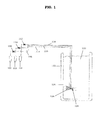
- FIG. 1 is a schematic view of a method and an apparatus for cleaning a submerged surface.
- an apparatus for cleaning a submerged surface includes a cleaning liquid supply 100, a non-reactive gas supply 102, and a reactive gas supply 104 connected to a fluid jet 126.
- the cleaning liquid supply 100 is configured to supply a cleaning liquid 100' ( FIG. 2 ) to the fluid jet 126 through a cleaning liquid line 114 via a pump 106.
- the flow opening in the cleaning liquid line 114 may be regulated with a first valve 108.
- the non-reactive gas supply 102 and the reactive gas supply 104 are configured to supply a non-reactive gas 102' and a reactive gas 104' ( FIG.
- non-reactive gas line 116 and a reactive gas line 118 may be regulated with a second valve 110 and a third valve 112, respectively.
- one or more pumps may be provided to drive the non-reactive gas 102' and the reactive gas 104' from the non-reactive gas supply 102 and the reactive gas supply 104, respectively.
- the fluid jet 126 may be arranged within a vessel 122 containing a liquid medium 120 so as to face a submerged surface 124 of the vessel 122.
- the liquid medium 120 may be water, although example embodiments are not limited thereto.
- the force generated by the fluids expelled therefrom may repel the fluid jet 126 and, thus, cause the fluid jet 126 to depart from an ideal or desired position relative to the submerged surface 124 of the vessel 122.
- the fluid jet 126 may be stabilized with a balancing jet 128.
- the balancing jet 128 may expel a secondary fluid in a direction opposite to the direction that the primary fluids are being expelled from the fluid jet 126.
- FIG. 1 illustrates a fluid jet 126 being used to clean an interior surface of the vessel 122, it should be understood that the fluid jet 126 may be used on a variety of other submerged surfaces (whether in a reactor facility or in other environments).
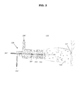
- FIG. 2 is a cross-sectional view of the fluid jet of FIG. 1 .
- the fluid jet 126 is configured to include a first passage 200, a second passage 202, and a third passage 204.
- the cleaning liquid 100' travels through the first passage 200
- the non-reactive gas 102' travels through the second passage 202
- the reactive gas 104' travels through the third passage 204.
- the first passage 200, second passage 202, and third passage 204 are designed such that the cleaning liquid 100', non-reactive gas 102', and reactive gas 104' are isolated from each other while en route to and while within the fluid jet 126 and mix with each other when expelled from the fluid jet 126 into the liquid medium 120.
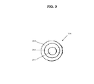
- FIG. 3 is a front view of the fluid jet of FIG. 2 .
- the fluid jet 126 may be configured such that the third passage 204 is concentrically arranged within the second passage 202.
- the second passage 202 may also be concentrically arranged within the first passage 200.
- the fluid jet 126 may be formed of a large cylinder structure, a medium cylinder structure arranged within the large cylinder structure, and a small cylinder structure arranged within the medium cylinder structure.
- the inner surface of the large cylinder structure and the outer surface of the medium cylinder structure define the first passage 200.
- the inner surface of the medium cylinder structure and the outer surface of the small cylinder structure define the second passage 202.
- a method of cleaning a submerged surface 124 covered by a liquid medium 120 includes injecting a cleaning liquid 100' with a submerged fluid jet 126 through the liquid medium 120 at the submerged surface 124.
- the method additionally includes introducing at least one of a non-reactive gas 102' and a reactive gas 104' with the cleaning liquid 100' through the submerged fluid jet 126.
- the "flame" of the fluid jet 126 facilitates the removal of "dust" and other unwanted materials from the submerged surface 124.
- the injecting step may include directing the cleaning liquid 100' at an interior surface of a vessel 122 covered by the liquid medium 120.
- the injecting step may include directing the cleaning liquid 100' at a component immersed in the liquid medium 120 (e.g., a mechanical part within the vessel 122).
- the cleaning liquid 100' may be directed at any surface in need of cleaning.
- the injecting step may include using water as the cleaning liquid 100'.
- the injecting and introducing steps may include configuring the submerged fluid jet 126 such that the cleaning liquid 100' and the at least one of the non-reactive gas 102' and the reactive gas 104' exit the submerged fluid jet 126 prior to mixing with each other.
- the injecting and introducing step may be performed with a triple concentric tuyere as the submerged fluid jet 126.
- the cleaning liquid 100' may be injected through a first passage 200 of the triple concentric tuyere
- the non-reactive gas 102' may be introduced through a second passage 202 of the triple concentric tuyere
- the reactive gas 104' may be introduced through a third passage 204 of the triple concentric tuyere.
- each of the cleaning liquid 100', the non-reactive gas 102', and the reactive gas 104' may be supplied through any of the first passage 200, the second passage 202, and the third passage 204.
- the non-reactive gas 102' may be supplied through the third passage 204
- the reactive gas 104' may be supplied through the second passage 202.
- the injecting and introducing steps may include configuring the triple concentric tuyere such that the first passage 200 surrounds the second passage 202 and the third passage 204. With this configuration, supplying the cleaning liquid 100' through the outer first passage 200 will help focus the inner-supplied non-reactive gas 102' and/or reactive gas 104' during their path toward the submerged surface 124, thereby reducing their premature diffusion into the liquid medium 120 and enhancing the cleaning of the submerged surface 124.
- the injecting and introducing may also include configuring the triple concentric tuyere such that the second passage 202 and/or the third passage 204 extends further from the submerged fluid jet 126 than the first passage 200. Such a configuration may help to further reduce the premature diffusion of the non-reactive gas 102' and/or reactive gas 104' into the liquid medium 120 during their path toward the submerged surface 124.
- the introducing step may include supplying the at least one of the non-reactive gas 102' and the reactive gas 104' as voids 206 (e.g., bubbles) that cavitate at an interface with the submerged surface 124 so as to facilitate a removal of deposits from the submerged surface 124.
- the introducing step may also include generating heat at an interface with the submerged surface 124 as a result of an absorption of the reactive gas 104' by at least one of the liquid medium 120 and the cleaning liquid 100'.
- the introducing step may further include increasing a pH at an interface with the submerged surface 124 as a result of an absorption of the reactive gas 104' by at least one of the liquid medium 120 and the cleaning liquid 100' so as to facilitate passivation of the submerged surface 124.
- a passive corrosion layer may be formed on the submerged surface 124.
- the non-reactive gas 102' and the reactive gas 104' may be co-injected so as to be simultaneously introduced with the cleaning liquid 100'.
- At least one of atmospheric air, nitrogen, and a noble gas may be used as the non-reactive gas 102'.
- at least one of ammonia and hydrazine may be used as the reactive gas 104'.
- the introducing step may include the use of hydrogen chloride as the reactive gas 104'.
- the use of water as the cleaning liquid 100' will result in the cleaning of the submerged surface 124 due to local fluid velocity.
- the local fluid velocity depends on the smoothness of the submerged surface 124, the impurities in the cleaning liquid 100' and the liquid medium 120, and the oxygen content of the cleaning liquid 100' and the liquid medium 120.
- the cleaning liquid 100' When the cleaning liquid 100' is augmented with the non-reactive gas 102', a relatively high frequency vibration is generated, thereby enhancing the mechanical removal of "dust" from the submerged surface 124.
- the entrained bubbles of the non-reactive gas 102' collapse at the liquid-solid interface of the liquid medium 120 and the submerged surface 124 via a phenomenon called cavitation to cause the relatively high frequency vibration.
- the bubble radius of the non-reactive gas 102' exiting the nozzle of the fluid jet 126 will be about five times that of the nozzle diameter.
- the frequency is about 600 Hz, although example embodiments are not limited thereto.
- the cleaning liquid 100' When the cleaning liquid 100' is augmented with the reactive gas 104' (with or without the non-reactive gas 102'), relatively high frequency vibrations with a larger magnitude acoustic pulse (acoustical pressure waves) are generated. Additionally, the absorption of the reactive gas 104' by the cleaning liquid 100' and/or liquid medium 120 causes a local temperature increase (heat of dissolution) while also causing dissolved gas to come out of solution. The resulting cavitation and heat increases the removal of "dust" from the submerged surface 124. Furthermore, the reactive gas 104' will cause a localized pH increase. The increased alkalinity decreases the corrosion rate by making the cleaned submerged surface 124 more passive.
- ammonia (NH 3 ) is used as the reactive gas 104'
- the chemical reaction for the dissolution of ammonia (NH 3 ) in water (H 2 O) is expressed below.
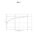
- FIG. 4 is a graph showing the relationship between the pH of the liquid medium and the quantity of ammonia injected as the reactive gas.
- the chemistry control in a typical boiling water reactor (BWR) is to maintain pure water with a conductivity of 0.10 - 0.15 ⁇ S/cm with a pH between 6.5 - 8.0.
- the effect of the introduction of ammonia as the reactive gas 104' during cleaning will likely be minimal in view of the relatively large volume of the liquid medium 120 in the vessel 122.
- the method of cleaning the submerged surface 124 may further include stabilizing the submerged fluid jet 126 with a balancing jet 128.
- a first force generated by a first jet exiting the submerged fluid jet 126 is countered by a second force generated by a second jet exiting the balancing jet 128.
- the magnitude of the first force may be about equal to that of the second force.
- the direction of the first force may be opposite that of the second force.
- the fluid jet 126 may be maintained in a desired position relative to the submerged surface 124.
Landscapes
- Engineering & Computer Science (AREA)
- Mechanical Engineering (AREA)
- Cleaning By Liquid Or Steam (AREA)
- Cleaning In General (AREA)
Applications Claiming Priority (1)
| Application Number | Priority Date | Filing Date | Title |
|---|---|---|---|
| US13/609,824 US9839925B2 (en) | 2012-09-11 | 2012-09-11 | Methods of cleaning a submerged surface using a fluid jet discharging a liquid/gas combination |
Publications (3)
| Publication Number | Publication Date |
|---|---|
| EP2705908A2 true EP2705908A2 (fr) | 2014-03-12 |
| EP2705908A3 EP2705908A3 (fr) | 2014-04-16 |
| EP2705908B1 EP2705908B1 (fr) | 2016-07-06 |
Family
ID=49170575
Family Applications (1)
| Application Number | Title | Priority Date | Filing Date |
|---|---|---|---|
| EP13183917.7A Active EP2705908B1 (fr) | 2012-09-11 | 2013-09-11 | Procédés de nettoyage de surface immergée à l'aide d'un jet de fluide gaz/liquide de décharge combiné |
Country Status (4)
| Country | Link |
|---|---|
| US (1) | US9839925B2 (fr) |
| EP (1) | EP2705908B1 (fr) |
| JP (1) | JP5830069B2 (fr) |
| ES (1) | ES2588277T3 (fr) |
Cited By (1)
| Publication number | Priority date | Publication date | Assignee | Title |
|---|---|---|---|---|
| CN109772244A (zh) * | 2019-03-12 | 2019-05-21 | 南昌汇达知识产权有限公司 | 一种反应釜及其清洗方法 |
Families Citing this family (2)
| Publication number | Priority date | Publication date | Assignee | Title |
|---|---|---|---|---|
| WO2016059972A1 (fr) * | 2014-10-14 | 2016-04-21 | 東レ株式会社 | Composition de semi-conducteur organique, élément photovoltaïque, dispositif de conversion photoélectrique, et procédé de fabrication d'élément photovoltaïque |
| CN111112180B (zh) * | 2019-11-29 | 2021-08-17 | 中广核研究院有限公司 | 闸门密封面海生物水下清理设备、设备组合及清理方法 |
Family Cites Families (21)
| Publication number | Priority date | Publication date | Assignee | Title |
|---|---|---|---|---|
| DE2349196A1 (de) | 1972-10-06 | 1974-04-18 | Uddeholms Ab | Verfahren zum entkohlen von chromreichem stahl |
| JPS5776778U (fr) | 1980-10-22 | 1982-05-12 | ||
| JPS6354982A (ja) | 1986-08-23 | 1988-03-09 | 結城 忠弘 | 洗浄方法 |
| JPH025884Y2 (fr) | 1987-12-23 | 1990-02-13 | ||
| JPH0347575A (ja) * | 1989-07-13 | 1991-02-28 | Senju Metal Ind Co Ltd | 洗浄方法および装置 |
| JPH06210252A (ja) | 1993-01-21 | 1994-08-02 | Uchinami Techno Clean:Kk | 水中洗浄方法及びその装置 |
| JPH08154880A (ja) | 1994-12-09 | 1996-06-18 | Kanematsu Eng Kk | 自動洗浄装置 |
| US5849091A (en) | 1997-06-02 | 1998-12-15 | Micron Technology, Inc. | Megasonic cleaning methods and apparatus |
| JP2000262992A (ja) | 1999-03-18 | 2000-09-26 | Toshiba Corp | 基板の洗浄方法 |
| JP2010135810A (ja) | 1999-08-31 | 2010-06-17 | Tadahiro Omi | 水溶液のpH及び酸化還元電位の制御方法及びその装置 |
| JP3875456B2 (ja) | 2000-06-29 | 2007-01-31 | 株式会社東芝 | 洗浄方法および洗浄装置 |
| JP3865602B2 (ja) | 2001-06-18 | 2007-01-10 | 大日本スクリーン製造株式会社 | 基板洗浄装置 |
| JP4767447B2 (ja) | 2001-07-17 | 2011-09-07 | 関西電力株式会社 | 管内洗浄流体混合器及び管内洗浄設備 |
| JP2005186045A (ja) | 2003-12-26 | 2005-07-14 | Arakawa Chem Ind Co Ltd | 洗浄装置及び該洗浄装置を用いた洗浄度評価装置 |
| JP2006214749A (ja) | 2005-02-01 | 2006-08-17 | Ebara Kogyo Senjo Kk | 原子炉圧力容器内除染方法 |
| JP5072062B2 (ja) | 2006-03-13 | 2012-11-14 | 栗田工業株式会社 | 水素ガス溶解洗浄水の製造方法、製造装置及び洗浄装置 |
| DE102008015042A1 (de) | 2008-03-14 | 2009-09-17 | Dürr Ecoclean GmbH | Vorrichtung und Verfahren zur Entgratung und/oder Reinigung eines in ein flüssiges Medium eingetauchten Werkstücks |
| US8567420B2 (en) | 2008-03-31 | 2013-10-29 | Kabushiki Kaisha Toshiba | Cleaning apparatus for semiconductor wafer |
| WO2010091342A2 (fr) * | 2009-02-06 | 2010-08-12 | Clyde Gergemann, Inc. | Souffleur de suie comportant une buse avec des jets atteignant les profondeurs et des jets de nettoyage de bord |
| LU91691B1 (en) | 2010-05-26 | 2011-11-28 | Wurth Paul Sa | Tuyere stock arrangement of a blast furnace |
| WO2012071614A1 (fr) * | 2010-12-01 | 2012-06-07 | The University Of Sydney | Appareil destiné à être utilisé dans la production d'acide nitrique |
-
2012
- 2012-09-11 US US13/609,824 patent/US9839925B2/en not_active Expired - Fee Related
-
2013
- 2013-09-04 JP JP2013182657A patent/JP5830069B2/ja active Active
- 2013-09-11 EP EP13183917.7A patent/EP2705908B1/fr active Active
- 2013-09-11 ES ES13183917.7T patent/ES2588277T3/es active Active
Non-Patent Citations (1)
| Title |
|---|
| None |
Cited By (1)
| Publication number | Priority date | Publication date | Assignee | Title |
|---|---|---|---|---|
| CN109772244A (zh) * | 2019-03-12 | 2019-05-21 | 南昌汇达知识产权有限公司 | 一种反应釜及其清洗方法 |
Also Published As
| Publication number | Publication date |
|---|---|
| US9839925B2 (en) | 2017-12-12 |
| EP2705908A3 (fr) | 2014-04-16 |
| JP5830069B2 (ja) | 2015-12-09 |
| EP2705908B1 (fr) | 2016-07-06 |
| US20140069468A1 (en) | 2014-03-13 |
| ES2588277T3 (es) | 2016-10-31 |
| JP2014054628A (ja) | 2014-03-27 |
Similar Documents
| Publication | Publication Date | Title |
|---|---|---|
| US7392814B2 (en) | Substrate processing apparatus and method | |
| CN101578688B (zh) | 基板的处理装置以及处理方法 | |
| JP2008246486A (ja) | ナノ流体生成装置および洗浄処理装置 | |
| EP2705908B1 (fr) | Procédés de nettoyage de surface immergée à l'aide d'un jet de fluide gaz/liquide de décharge combiné | |
| KR101209463B1 (ko) | 미세기포펌프를 이용한 미세기포 혼합액체 발생장치 | |
| TWI355003B (fr) | ||
| JP2008272719A (ja) | 微細気泡発生装置 | |
| JP2008212788A (ja) | 洗浄装置及び洗浄方法 | |
| JP5352600B2 (ja) | 管内面に対するウォータージェットピーニングによる残留応力改善方法及びその装置 | |
| WO2017056323A1 (fr) | Dispositif pour la dissolution d'oxygène dans l'eau et procédé pour la dissolution d'oxygène dans l'eau l'utilisant | |
| KR20150056182A (ko) | 오존 미세 기포를 이용한 유기물 세정 장치 | |
| JP5024144B2 (ja) | 気体溶解器 | |
| JP2008021672A (ja) | ガス過飽和溶液を用いた超音波洗浄方法及び洗浄装置 | |
| CN117276139A (zh) | 湿制程处理设备、电池片的刻蚀方法及电池片的抛光方法 | |
| JP2004221343A (ja) | 超音波洗浄装置 | |
| KR101291637B1 (ko) | 버블 생성장치 | |
| JP5291312B2 (ja) | 酸洗装置及び方法 | |
| JP2012250302A (ja) | ナノバブル循環型研磨装置 | |
| JP2007309864A (ja) | 除染方法、除染装置および原子力施設 | |
| JPWO2015030035A1 (ja) | 洗浄装置および洗浄方法 | |
| KR100862231B1 (ko) | 세정액 분사 장치 및 이를 갖는 기판 세정 장치 | |
| KR102369944B1 (ko) | 미세기포 발생노즐 및 그를 포함하는 미세기포 발생장치 | |
| KR101846265B1 (ko) | 초음파를 이용한 배관의 플러싱 시스템 | |
| JP2009178702A (ja) | 気液混合設備 | |
| JP5610360B1 (ja) | 超音波による液体噴射式洗浄機 |
Legal Events
| Date | Code | Title | Description |
|---|---|---|---|
| PUAI | Public reference made under article 153(3) epc to a published international application that has entered the european phase |
Free format text: ORIGINAL CODE: 0009012 |
|
| AK | Designated contracting states |
Kind code of ref document: A2 Designated state(s): AL AT BE BG CH CY CZ DE DK EE ES FI FR GB GR HR HU IE IS IT LI LT LU LV MC MK MT NL NO PL PT RO RS SE SI SK SM TR |
|
| AX | Request for extension of the european patent |
Extension state: BA ME |
|
| PUAL | Search report despatched |
Free format text: ORIGINAL CODE: 0009013 |
|
| AK | Designated contracting states |
Kind code of ref document: A3 Designated state(s): AL AT BE BG CH CY CZ DE DK EE ES FI FR GB GR HR HU IE IS IT LI LT LU LV MC MK MT NL NO PL PT RO RS SE SI SK SM TR |
|
| AX | Request for extension of the european patent |
Extension state: BA ME |
|
| RIC1 | Information provided on ipc code assigned before grant |
Ipc: B08B 3/02 20060101ALI20140310BHEP Ipc: B05B 7/06 20060101ALI20140310BHEP Ipc: B01J 19/00 20060101ALI20140310BHEP Ipc: B08B 9/093 20060101AFI20140310BHEP Ipc: B08B 3/10 20060101ALI20140310BHEP |
|
| 17P | Request for examination filed |
Effective date: 20141016 |
|
| RBV | Designated contracting states (corrected) |
Designated state(s): AL AT BE BG CH CY CZ DE DK EE ES FI FR GB GR HR HU IE IS IT LI LT LU LV MC MK MT NL NO PL PT RO RS SE SI SK SM TR |
|
| GRAP | Despatch of communication of intention to grant a patent |
Free format text: ORIGINAL CODE: EPIDOSNIGR1 |
|
| INTG | Intention to grant announced |
Effective date: 20160310 |
|
| GRAS | Grant fee paid |
Free format text: ORIGINAL CODE: EPIDOSNIGR3 |
|
| GRAA | (expected) grant |
Free format text: ORIGINAL CODE: 0009210 |
|
| AK | Designated contracting states |
Kind code of ref document: B1 Designated state(s): AL AT BE BG CH CY CZ DE DK EE ES FI FR GB GR HR HU IE IS IT LI LT LU LV MC MK MT NL NO PL PT RO RS SE SI SK SM TR |
|
| REG | Reference to a national code |
Ref country code: GB Ref legal event code: FG4D |
|
| REG | Reference to a national code |
Ref country code: AT Ref legal event code: REF Ref document number: 810329 Country of ref document: AT Kind code of ref document: T Effective date: 20160715 Ref country code: CH Ref legal event code: EP |
|
| REG | Reference to a national code |
Ref country code: IE Ref legal event code: FG4D |
|
| REG | Reference to a national code |
Ref country code: DE Ref legal event code: R096 Ref document number: 602013009076 Country of ref document: DE |
|
| REG | Reference to a national code |
Ref country code: SE Ref legal event code: TRGR |
|
| REG | Reference to a national code |
Ref country code: ES Ref legal event code: FG2A Ref document number: 2588277 Country of ref document: ES Kind code of ref document: T3 Effective date: 20161031 |
|
| REG | Reference to a national code |
Ref country code: NL Ref legal event code: MP Effective date: 20160706 |
|
| REG | Reference to a national code |
Ref country code: LT Ref legal event code: MG4D |
|
| REG | Reference to a national code |
Ref country code: AT Ref legal event code: MK05 Ref document number: 810329 Country of ref document: AT Kind code of ref document: T Effective date: 20160706 |
|
| PG25 | Lapsed in a contracting state [announced via postgrant information from national office to epo] |
Ref country code: HR Free format text: LAPSE BECAUSE OF FAILURE TO SUBMIT A TRANSLATION OF THE DESCRIPTION OR TO PAY THE FEE WITHIN THE PRESCRIBED TIME-LIMIT Effective date: 20160706 Ref country code: NL Free format text: LAPSE BECAUSE OF FAILURE TO SUBMIT A TRANSLATION OF THE DESCRIPTION OR TO PAY THE FEE WITHIN THE PRESCRIBED TIME-LIMIT Effective date: 20160706 Ref country code: IS Free format text: LAPSE BECAUSE OF FAILURE TO SUBMIT A TRANSLATION OF THE DESCRIPTION OR TO PAY THE FEE WITHIN THE PRESCRIBED TIME-LIMIT Effective date: 20161106 Ref country code: LT Free format text: LAPSE BECAUSE OF FAILURE TO SUBMIT A TRANSLATION OF THE DESCRIPTION OR TO PAY THE FEE WITHIN THE PRESCRIBED TIME-LIMIT Effective date: 20160706 Ref country code: IT Free format text: LAPSE BECAUSE OF FAILURE TO SUBMIT A TRANSLATION OF THE DESCRIPTION OR TO PAY THE FEE WITHIN THE PRESCRIBED TIME-LIMIT Effective date: 20160706 Ref country code: NO Free format text: LAPSE BECAUSE OF FAILURE TO SUBMIT A TRANSLATION OF THE DESCRIPTION OR TO PAY THE FEE WITHIN THE PRESCRIBED TIME-LIMIT Effective date: 20161006 Ref country code: RS Free format text: LAPSE BECAUSE OF FAILURE TO SUBMIT A TRANSLATION OF THE DESCRIPTION OR TO PAY THE FEE WITHIN THE PRESCRIBED TIME-LIMIT Effective date: 20160706 Ref country code: FI Free format text: LAPSE BECAUSE OF FAILURE TO SUBMIT A TRANSLATION OF THE DESCRIPTION OR TO PAY THE FEE WITHIN THE PRESCRIBED TIME-LIMIT Effective date: 20160706 |
|
| PG25 | Lapsed in a contracting state [announced via postgrant information from national office to epo] |
Ref country code: LV Free format text: LAPSE BECAUSE OF FAILURE TO SUBMIT A TRANSLATION OF THE DESCRIPTION OR TO PAY THE FEE WITHIN THE PRESCRIBED TIME-LIMIT Effective date: 20160706 Ref country code: GR Free format text: LAPSE BECAUSE OF FAILURE TO SUBMIT A TRANSLATION OF THE DESCRIPTION OR TO PAY THE FEE WITHIN THE PRESCRIBED TIME-LIMIT Effective date: 20161007 Ref country code: PL Free format text: LAPSE BECAUSE OF FAILURE TO SUBMIT A TRANSLATION OF THE DESCRIPTION OR TO PAY THE FEE WITHIN THE PRESCRIBED TIME-LIMIT Effective date: 20160706 Ref country code: PT Free format text: LAPSE BECAUSE OF FAILURE TO SUBMIT A TRANSLATION OF THE DESCRIPTION OR TO PAY THE FEE WITHIN THE PRESCRIBED TIME-LIMIT Effective date: 20161107 Ref country code: BE Free format text: LAPSE BECAUSE OF NON-PAYMENT OF DUE FEES Effective date: 20160706 Ref country code: AT Free format text: LAPSE BECAUSE OF FAILURE TO SUBMIT A TRANSLATION OF THE DESCRIPTION OR TO PAY THE FEE WITHIN THE PRESCRIBED TIME-LIMIT Effective date: 20160706 |
|
| REG | Reference to a national code |
Ref country code: DE Ref legal event code: R119 Ref document number: 602013009076 Country of ref document: DE |
|
| PG25 | Lapsed in a contracting state [announced via postgrant information from national office to epo] |
Ref country code: MC Free format text: LAPSE BECAUSE OF FAILURE TO SUBMIT A TRANSLATION OF THE DESCRIPTION OR TO PAY THE FEE WITHIN THE PRESCRIBED TIME-LIMIT Effective date: 20160706 Ref country code: EE Free format text: LAPSE BECAUSE OF FAILURE TO SUBMIT A TRANSLATION OF THE DESCRIPTION OR TO PAY THE FEE WITHIN THE PRESCRIBED TIME-LIMIT Effective date: 20160706 Ref country code: RO Free format text: LAPSE BECAUSE OF FAILURE TO SUBMIT A TRANSLATION OF THE DESCRIPTION OR TO PAY THE FEE WITHIN THE PRESCRIBED TIME-LIMIT Effective date: 20160706 |
|
| PLBE | No opposition filed within time limit |
Free format text: ORIGINAL CODE: 0009261 |
|
| STAA | Information on the status of an ep patent application or granted ep patent |
Free format text: STATUS: NO OPPOSITION FILED WITHIN TIME LIMIT |
|
| PG25 | Lapsed in a contracting state [announced via postgrant information from national office to epo] |
Ref country code: CZ Free format text: LAPSE BECAUSE OF FAILURE TO SUBMIT A TRANSLATION OF THE DESCRIPTION OR TO PAY THE FEE WITHIN THE PRESCRIBED TIME-LIMIT Effective date: 20160706 Ref country code: DK Free format text: LAPSE BECAUSE OF FAILURE TO SUBMIT A TRANSLATION OF THE DESCRIPTION OR TO PAY THE FEE WITHIN THE PRESCRIBED TIME-LIMIT Effective date: 20160706 Ref country code: SK Free format text: LAPSE BECAUSE OF FAILURE TO SUBMIT A TRANSLATION OF THE DESCRIPTION OR TO PAY THE FEE WITHIN THE PRESCRIBED TIME-LIMIT Effective date: 20160706 Ref country code: BG Free format text: LAPSE BECAUSE OF FAILURE TO SUBMIT A TRANSLATION OF THE DESCRIPTION OR TO PAY THE FEE WITHIN THE PRESCRIBED TIME-LIMIT Effective date: 20161006 Ref country code: SM Free format text: LAPSE BECAUSE OF FAILURE TO SUBMIT A TRANSLATION OF THE DESCRIPTION OR TO PAY THE FEE WITHIN THE PRESCRIBED TIME-LIMIT Effective date: 20160706 |
|
| 26N | No opposition filed |
Effective date: 20170407 |
|
| REG | Reference to a national code |
Ref country code: IE Ref legal event code: MM4A |
|
| REG | Reference to a national code |
Ref country code: FR Ref legal event code: ST Effective date: 20170531 |
|
| PG25 | Lapsed in a contracting state [announced via postgrant information from national office to epo] |
Ref country code: IE Free format text: LAPSE BECAUSE OF NON-PAYMENT OF DUE FEES Effective date: 20160911 Ref country code: FR Free format text: LAPSE BECAUSE OF NON-PAYMENT OF DUE FEES Effective date: 20160930 Ref country code: DE Free format text: LAPSE BECAUSE OF NON-PAYMENT OF DUE FEES Effective date: 20170401 |
|
| PG25 | Lapsed in a contracting state [announced via postgrant information from national office to epo] |
Ref country code: SI Free format text: LAPSE BECAUSE OF FAILURE TO SUBMIT A TRANSLATION OF THE DESCRIPTION OR TO PAY THE FEE WITHIN THE PRESCRIBED TIME-LIMIT Effective date: 20160706 Ref country code: LU Free format text: LAPSE BECAUSE OF NON-PAYMENT OF DUE FEES Effective date: 20160911 |
|
| GBPC | Gb: european patent ceased through non-payment of renewal fee |
Effective date: 20170911 |
|
| PG25 | Lapsed in a contracting state [announced via postgrant information from national office to epo] |
Ref country code: CY Free format text: LAPSE BECAUSE OF FAILURE TO SUBMIT A TRANSLATION OF THE DESCRIPTION OR TO PAY THE FEE WITHIN THE PRESCRIBED TIME-LIMIT Effective date: 20160706 Ref country code: HU Free format text: LAPSE BECAUSE OF FAILURE TO SUBMIT A TRANSLATION OF THE DESCRIPTION OR TO PAY THE FEE WITHIN THE PRESCRIBED TIME-LIMIT; INVALID AB INITIO Effective date: 20130911 |
|
| PG25 | Lapsed in a contracting state [announced via postgrant information from national office to epo] |
Ref country code: MK Free format text: LAPSE BECAUSE OF FAILURE TO SUBMIT A TRANSLATION OF THE DESCRIPTION OR TO PAY THE FEE WITHIN THE PRESCRIBED TIME-LIMIT Effective date: 20160706 Ref country code: TR Free format text: LAPSE BECAUSE OF FAILURE TO SUBMIT A TRANSLATION OF THE DESCRIPTION OR TO PAY THE FEE WITHIN THE PRESCRIBED TIME-LIMIT Effective date: 20160706 Ref country code: MT Free format text: LAPSE BECAUSE OF NON-PAYMENT OF DUE FEES Effective date: 20160930 |
|
| PG25 | Lapsed in a contracting state [announced via postgrant information from national office to epo] |
Ref country code: GB Free format text: LAPSE BECAUSE OF NON-PAYMENT OF DUE FEES Effective date: 20170911 |
|
| PG25 | Lapsed in a contracting state [announced via postgrant information from national office to epo] |
Ref country code: AL Free format text: LAPSE BECAUSE OF FAILURE TO SUBMIT A TRANSLATION OF THE DESCRIPTION OR TO PAY THE FEE WITHIN THE PRESCRIBED TIME-LIMIT Effective date: 20160706 |
|
| PGFP | Annual fee paid to national office [announced via postgrant information from national office to epo] |
Ref country code: SE Payment date: 20240820 Year of fee payment: 12 |
|
| PGFP | Annual fee paid to national office [announced via postgrant information from national office to epo] |
Ref country code: ES Payment date: 20241001 Year of fee payment: 12 |
|
| PGFP | Annual fee paid to national office [announced via postgrant information from national office to epo] |
Ref country code: CH Payment date: 20241001 Year of fee payment: 12 |
|
| REG | Reference to a national code |
Ref country code: CH Ref legal event code: H13 Free format text: ST27 STATUS EVENT CODE: U-0-0-H10-H13 (AS PROVIDED BY THE NATIONAL OFFICE) Effective date: 20260425 |