EP2705911A2 - Dispositif de transport de brames - Google Patents
Dispositif de transport de brames Download PDFInfo
- Publication number
- EP2705911A2 EP2705911A2 EP13176451.6A EP13176451A EP2705911A2 EP 2705911 A2 EP2705911 A2 EP 2705911A2 EP 13176451 A EP13176451 A EP 13176451A EP 2705911 A2 EP2705911 A2 EP 2705911A2
- Authority
- EP
- European Patent Office
- Prior art keywords
- hood
- receptacle
- slab
- floor
- slabs
- Prior art date
- Legal status (The legal status is an assumption and is not a legal conclusion. Google has not performed a legal analysis and makes no representation as to the accuracy of the status listed.)
- Granted
Links
Images


Classifications
-
- B—PERFORMING OPERATIONS; TRANSPORTING
- B21—MECHANICAL METAL-WORKING WITHOUT ESSENTIALLY REMOVING MATERIAL; PUNCHING METAL
- B21B—ROLLING OF METAL
- B21B39/00—Arrangements for moving, supporting, or positioning work, or controlling its movement, combined with or arranged in, or specially adapted for use in connection with, metal-rolling mills
-
- B—PERFORMING OPERATIONS; TRANSPORTING
- B65—CONVEYING; PACKING; STORING; HANDLING THIN OR FILAMENTARY MATERIAL
- B65D—CONTAINERS FOR STORAGE OR TRANSPORT OF ARTICLES OR MATERIALS, e.g. BAGS, BARRELS, BOTTLES, BOXES, CANS, CARTONS, CRATES, DRUMS, JARS, TANKS, HOPPERS, FORWARDING CONTAINERS; ACCESSORIES, CLOSURES, OR FITTINGS THEREFOR; PACKAGING ELEMENTS; PACKAGES
- B65D88/00—Large containers
- B65D88/02—Large containers rigid
- B65D88/12—Large containers rigid specially adapted for transport
- B65D88/122—Large containers rigid specially adapted for transport with access from above
- B65D88/124—Large containers rigid specially adapted for transport with access from above closable top
- B65D88/126—Large containers rigid specially adapted for transport with access from above closable top by rigid element, e.g. lid
Definitions
- the present invention relates to a device for transporting at least one slab, preferably at least one slab emerging from a continuous casting plant.
- the continuous casting products are usually produced in such a way that they still have a very high heat content when they leave the respective plant.
- the average temperature of a slab when leaving a continuous casting plant is still about 1000 ° C.
- the slabs - or other continuous casting products, such as billets, rods, etc. - are then usually spent in warehouses, where they are stored until further processing in a rolling mill for the production of a finish-rolled product.
- the slabs usually cool down strongly and can even reach ambient temperature.
- the slabs In order to be processed in the rolling process, the slabs must then be reheated to the working temperature of the rolling process, which is typically 1200 ° C. Accordingly, a high energy input is necessary to bring the cooled slabs from the slab storage back to hot rolling process temperature. This results in high costs and the environmental impact of a corresponding process suffers.
- insulation blankets which are used to transport the slabs from the continuous caster to a rolling line.
- An appropriate facility for Keeping warm emerging from a continuous casting slabs is for example from the WO 2008/025325 A1 known.
- the slabs are transported here in the corresponding closed containers via roller tables and then removed from the containers before the hot rolling mill.
- the said isolation devices of the prior art are limited in that they are each bound to a specific means of transport, for example to the presence of roller tracks or railway wagons or transport trailers with insulated floors.
- the device for transporting at least one slab comprises a floor for receiving the at least one slab and a hood which can be placed on the floor.
- the floor has at least one receptacle for receiving and removing at least the total weight of the hood and the at least one slab received on the floor.
- the device for transporting is very flexible with respect to the means of transport used.
- the total weight is carried by the rollers of the roller conveyor, for example, on the usual in steel mills lifting equipment, such as lifting cranes, be lifted and implemented together with the content.
- lifting equipment such as lifting cranes
- the device is also designed to be self-supporting, so that the floor can also support itself.
- the dead weight of the floor can also be recorded via the receptacles so that the apparatus can be transported on the most diverse means of transport without being structurally damaged.
- the device is preferably dimensioned such that at least two slabs can be stacked one above the other on the at least one receptacle.
- the efficiency of the device can be further increased because inter alia, the amount of heat introduced into the device is higher and thus the slabs can be kept warm longer. In this way it can also be achieved that a slower decrease in the heat in the stacked slabs can be achieved, as in the transport of a single slab.
- the hood has at least one removal means for removing the weight of at least one further device stacked on the hood, wherein the at least one removal means removes the weight to the bottom of the lower device.
- the proposed device for transporting slabs in such a way that they can be stacked and the necessary base area can accordingly be reduced in a slab bearing or a higher number of slabs can be temporarily stored on a given base area.
- this is also achieved in that at least two slabs stacked one above the other can be accommodated in a single device for transporting.
- the device is compatible with commonly used in steel mills transport and lifting equipment, preferably heavy duty low loaders, railway cars, roller tables and cranes and other lifting devices, particularly preferably the hood and / or the bottom of the device has corresponding stop devices for crane and lifting devices.
- transport and lifting equipment preferably heavy duty low loaders, railway cars, roller tables and cranes and other lifting devices, particularly preferably the hood and / or the bottom of the device has corresponding stop devices for crane and lifting devices.
- the existing transport and lifting devices can be achieved in a steel mill, for example, with the existing low loaders, railway cars and crane devices, which can then all be used in conjunction with existing roller tables for handling the respective devices.
- the floor is particularly preferably designed so that it can be used on roller tables.
- it is sufficiently flat on its underside to be guided accordingly over the roller tables.
- the hood is preferably connectable via locking means to the ground so that the floor, hood and the slab received on the floor or the slabs received can be lifted by means of a stop means arranged on the hood. Also by this leaves significantly simplify the handling of the device, since a corresponding lifting device must be struck only on the top of the hood.
- the hood and / or the floor guide means for guiding the hood in its Aufsetzposition or locking position on the ground.
- a simple lifting and re-putting the hood on the ground can be achieved to allow loading of the soil with slabs and then to achieve a quick and easy closing.
- Particularly suitable for this purpose are refractory bricks, preferably based on silicate, which are applied to the corresponding receptacles in such a way that the slabs can be laid on the corresponding refractory bricks and the loads registered by the slabs are removed directly on the receptacles of the floor.
- the refractory bricks are preferably positioned over anchors on the receptacles.
- the number of refractory bricks is limited to the number required for the safe removal of the slab weight used.
- a further insulation of the soil, in particular between the shots or between on the recordings launched refractory bricks, can be achieved with advantage over a Blähton sectionung, which is taken in the ground.
- the hood preferably has a support structure on which wall elements are advantageously mounted, which are lined with insulating materials.
- the insulation can also be designed in several layers.
- the device has identification means for identifying the content recorded on the ground, so that a largely automated logistics can be applied.
- FIG. 1 shows a device 1 for transporting at least one slab, not shown in this figure, wherein the device 1 comprises a bottom 2 and a bottom 2 can be placed on the hood 3.
- the device 1 comprises a bottom 2 and a bottom 2 can be placed on the hood 3.
- FIGS. 2 to 11 different aspects and details of the proposed device 1 are shown.
- the bottom 2 of the device for example, in the FIGS. 5 and 6 Shown in detail recordings for receiving and removing at least the total weight of the hood 3 and launched on the floor 2 and in the Figures 1 and 2 Slabs not shown on.
- the bottom 2 or the recordings are also self-supporting.
- the dead weight of the bottom 2 can also be recorded via the receptacles.
- the entire device 1 is thus self-supporting.
- the hood 3 is in the in the FIG. 1 shown lifted off the floor 2, so that the empty device 1 is shown open.
- FIG. 2 shows in a schematic perspective view of the device 1 in a closed state, namely when mounted on the bottom 2 hood 3.
- the in FIG. 2 The state shown is the state used to transport the slab and suitable condition.
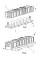
- FIG. 3 shows the device 1 again with lifted from the bottom 2 hood 3, in which case three arranged on the bottom 2 slabs 4 are shown, which are received in the device 1.
- the shots of the bottom 2 are dimensioned accordingly so that they - in addition to the weight of the bottom 2 and the weight of the hood 3 - also record and remove the weight of the three stacked slabs 4.
- the floor 3 is structured such that it can receive and remove the said weights, without requiring separate support of the floor 3.
- FIG. 4 shows schematically the device 1 when transported on a schematically indicated railway wagon 5.
- the device 1 is also used for transport on other, in the field of steel production Transport and lifting means suitable because the transport and lifting means by the design of the bottom 2 no own support of recorded in the device 1 slabs must provide.
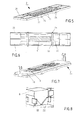
- FIGS. 5 and 6 schematically the bottom 2 of the device 1 with corresponding longitudinal members 20 and cross members 22 is shown.
- the longitudinal members 20 and cross member 22 are formed so that they form the respective receptacles for receiving and removing at least the total weight of the bottom 2, the hood 3, as well as recorded on the bottom 2 slabs 4.
- the side members 20 and the cross member 22 are dimensioned so that a deflection of the bottom 2 does not occur appreciably even at full load of the device 1 and according to the recordings forming longitudinal beams 20 and cross members 22 slabs safely and without distortion or deformation of the Floor 2 can be supported.
- the cross member 22 have in their extension stops 24, which serve for coupling a lifting device, such as a crane. At the stops 24, the bottom 2 can be lifted together with the hood shown in the preceding figures and the slabs 4 received therein via a corresponding lifting device and be relocated to another means of transport, or stored in a warehouse, preferably stacked, are.
- the structure, dimensioning and design of the floor 2 differs from those known in the prior art, inter alia, in that supporting the floor 2 at several points or areas, for example by a roller conveyor, is not necessary, but rather the device 1, for example at the stops 24 without losing their structural integrity.
- FIG. 6 is schematically in a plan view the in FIG. 5 shown frame structure, wherein schematically a large slab 4 and darker hatched - a smallest recordable slab 4 'are recorded in their dimensions.
- the large slab 4 is both on the longitudinal members 20 and on the cross members 22, a smallest slab 4 ', however, only on the longitudinal members 20.
- the distances between the cross members 22 and the longitudinal members 20 are designed accordingly that all in slabs produced on the respective continuous casting plant can be accommodated on the floor 2 so that the respective slabs 4, 4 'can be supported correspondingly via the receptacles, for example in the form of the crossbeams 22 and longitudinal members 20.
- the device Since an essential aspect of the proposed device 1 is to achieve a particularly good insulation of the heat energy absorbed in the slabs 4, 4 'relative to the outside and to correspondingly reduce the energy loss, the device is correspondingly thermally insulated.
- FIGS. 7 and 8 shown the ground 2 in the area through the in FIG. 5 shown longitudinal members 20 and cross member 22, which act as recordings, with corresponding, high strength insulation 6 in the form of refractory bricks, preferably based on silicate, occupied.
- the slabs as in FIG. 6 shown, are placed on the refractory bricks 6 so that the corresponding weight of the slabs rests directly on the longitudinal members 20 and cross members 22 and is correspondingly removed into the structure of the bottom 2.
- a further insulation against the radiant heat of the soil is achieved via an introduced between the refractory bricks 6 Blumbleton sectionung 60, by means of which the bottom 2 is insulated towards the bottom.
- FIGS. 5 and 6 shown further frame members 26 which surround the longitudinal members 20 and cross member 22, serve to accommodate insulating elements, which are necessary for a complete shield, and continue to serve as a receptacle for ablating the registered through the hood 3 loads and transfer to the receptacles 20, 22.
- the refractory bricks 6 are preferably slightly above the Blähton sectionung 60 out, so that a direct contact of the respective slab underside with the Blähton sectionung 60 does not take place.
- FIG. 8 schematically shows an exemplary arrangement of the refractory bricks 6 on the cross members 22, wherein 6 anchors corresponding to the anchoring of the refractory bricks 62 are positioned on the cross members 22, by means of which the refractory bricks 6 can be held in position.
- About the material thickness of the armature 62 is in the in FIG. 8 embodiment shown also further provided an expansion joint between the individual refractory bricks 6, so that different temperatures of the refractory bricks 6 does not lead to excessive stress on the refractory material.
- the insulation in the form of refractory bricks 6, the Blähton sectionung 60, as well as the insulation elements 62 may be formed for quick change or refilling in case of wear.
- the insulation elements 62 are either hung on the hood 3 or can be quickly replaced via detachable connections.
- the refractory bricks 6 can also be easily lifted out of the anchors 62 shown and replaced with new refractory bricks.
- FIGS. 9 and 10 schematically the construction of the hood 3 is shown, which according to FIG. 9 consists of a support structure 30, which with, as from FIG. 10 can be seen, walls, for example, trapezoidal sheets 32 is filled.
- stops 34 which serve to lift the hood 3 by means of a crane or other lifting device of the bottom 2 to allow filling or emptying of the device 1.
- the stops 34 may also serve, with a suitable dimensioning, to raise the hood 3 together with the bottom 2 and the slabs set up on the bottom 2.
- receptacles 36 are provided in addition to the stop 34, which serve to receive the weight of another device 1 and remove.
- the support structure 30 of the hood 3 is correspondingly dimensioned so that a lifting of the device 1 on the stop 34 and / or a settling of a further device 1 on the receptacles 36 on an already loaded device 1 is possible.
- the frame structure 30 and the walls 32 are lined with Isoliermodulen 64, wherein, as shown in the detailed illustration, the individual Isoliermodule 64 are connected via anchors 66 with the corresponding support structure 30 and the trapezoidal sheets 32.
- a transverse plate 68 attached to the lowermost insulating module 64 is provided, by means of which the individual insulating modules 64 of a wall are prevented from slipping off.
- 2 guide means 70 are provided on the bottom, in which complementary guide means 72 engage the hood 3. Accordingly, when lowering the hood 3 to the floor 2, the guide means 72 provided on the hood is guided in the guide means 70 provided on the floor 2 in such a way that a precise and precisely aligned placing of the hood 3 on the floor 2 is achieved.
- the hood 3 can still be locked to the bottom 2.
- this lock is then designed so that the entire device 2 can be completely raised over the stop 34, so both the hood 3 and the bottom 2 can be raised with a possibly recorded thereon slab on the cover 34 provided on the hood 3 ,
- the device 1 Due to the construction shown and in particular the corresponding design of the images of the bottom 2 ensures that the device 1 is very flexible and can be transported on roller skates due to the flat bottom of the shots forming longitudinal supports 20 and cross member. About the stops 24, 34 but the device 1 can also be raised in lifting devices, such as cranes, and then in a simple manner to a heavy-load low loader or the example in FIG. 4 shown railroad car 5 are implemented. Furthermore, the stackability of the individual devices is such that two or more of the insulating boxes shown can be stacked one above the other.
- the content of the device 1 can preferably be identified via corresponding identification means.
- identification means for example, offer RFID transponder or other means of identification, which can be detected automatically.
- the insulation box described can be operated with optimally short open times, since it can be opened and closed at the appropriate intended processing locations. Due to the corresponding design of the floor, the insulating box can be placed directly on the continuous casting plant so that the finished cast slab can be directly absorbed, and on the other hand, the Isolierbox due to the structural design of the Soil can be lifted directly to the beginning of the hot rolling mill, whereby the actual open times can be kept short.
- the insulating box is self-sufficient in that it requires no additional power supply or power supply, but acts as a passive element. It can be used accordingly without blocking transport or lifting capacity as a buffer for decoupling the workflow between continuous casting and hot rolling mill.
- it is also stackable, taking advantage of the available storage space almost as well as uninsulated boxes. The stackability makes it a slightly larger volume immediately.
- the insulation box makes a significant contribution to reducing the environmental impact in this context.
Landscapes
- Engineering & Computer Science (AREA)
- Mechanical Engineering (AREA)
- Heat Treatments In General, Especially Conveying And Cooling (AREA)
- Furnace Housings, Linings, Walls, And Ceilings (AREA)
- Loading Or Unloading Of Vehicles (AREA)
Applications Claiming Priority (1)
| Application Number | Priority Date | Filing Date | Title |
|---|---|---|---|
| DE201210215769 DE102012215769A1 (de) | 2012-09-05 | 2012-09-05 | Heiße Kiste |
Publications (3)
| Publication Number | Publication Date |
|---|---|
| EP2705911A2 true EP2705911A2 (fr) | 2014-03-12 |
| EP2705911A3 EP2705911A3 (fr) | 2014-06-18 |
| EP2705911B1 EP2705911B1 (fr) | 2018-09-26 |
Family
ID=48875515
Family Applications (1)
| Application Number | Title | Priority Date | Filing Date |
|---|---|---|---|
| EP13176451.6A Active EP2705911B1 (fr) | 2012-09-05 | 2013-07-15 | Dispositif de transport de brames |
Country Status (2)
| Country | Link |
|---|---|
| EP (1) | EP2705911B1 (fr) |
| DE (1) | DE102012215769A1 (fr) |
Citations (2)
| Publication number | Priority date | Publication date | Assignee | Title |
|---|---|---|---|---|
| EP0042652A1 (fr) | 1980-06-20 | 1981-12-30 | Trefileries De Bourbourg | Procédé pour la formation de paquets de rouleaux de treillis en fil métallique |
| WO2008025325A1 (fr) | 2006-09-01 | 2008-03-06 | Sms Demag Ag | Dispositif de maintien à température de brames sortant d'une installation de coulée continue |
Family Cites Families (3)
| Publication number | Priority date | Publication date | Assignee | Title |
|---|---|---|---|---|
| TW336184B (en) * | 1995-01-11 | 1998-07-11 | Tippins Inc | Intermediate thickness slab caster and inline hot strip and plate line, method of processing metal slabs and slab container |
| US8002134B2 (en) * | 2006-04-20 | 2011-08-23 | Cakeboxx, Llc | Doorless intermodal cargo container |
| FI121747B (fi) * | 2009-06-12 | 2011-03-31 | Oy Langh Ship Ab | Kuljetusteline |
-
2012
- 2012-09-05 DE DE201210215769 patent/DE102012215769A1/de not_active Withdrawn
-
2013
- 2013-07-15 EP EP13176451.6A patent/EP2705911B1/fr active Active
Patent Citations (2)
| Publication number | Priority date | Publication date | Assignee | Title |
|---|---|---|---|---|
| EP0042652A1 (fr) | 1980-06-20 | 1981-12-30 | Trefileries De Bourbourg | Procédé pour la formation de paquets de rouleaux de treillis en fil métallique |
| WO2008025325A1 (fr) | 2006-09-01 | 2008-03-06 | Sms Demag Ag | Dispositif de maintien à température de brames sortant d'une installation de coulée continue |
Also Published As
| Publication number | Publication date |
|---|---|
| DE102012215769A1 (de) | 2014-03-06 |
| EP2705911A3 (fr) | 2014-06-18 |
| EP2705911B1 (fr) | 2018-09-26 |
Similar Documents
| Publication | Publication Date | Title |
|---|---|---|
| DE602006000358T2 (de) | Anordnung und Verfahren zum Verpacken eines Gestells für Computer, Gestell für Computer und Palette für dieses Gestell | |
| EP2268562B1 (fr) | Station pour navettes et dispositif de stockage pour navettes | |
| EP2485969B1 (fr) | Magasin de stockage à navettes, station de navettes et procédé pour faire fonctionner le magasin | |
| EP3194232B1 (fr) | Wagon de marchandises équipé d'une superstructure, dispositif de transbordement de marchandises avec des tels wagons de marchandises et procédé de transbordement de marchandises | |
| WO2008046728A1 (fr) | Chariot de transport relié au sol, en particulier pour le transport de conteneurs | |
| DE102019106033A1 (de) | Regalbediengerät zum Verladen von stapelfähigen Waren und Logistiksystem mit einem solchen Regalbediengerät | |
| AT506918A1 (de) | Aufnahmevorrichtung für ein förderfahrzeug | |
| DE102008052238B4 (de) | Einrichtung zum Transportieren von im Wesentlichen langgestreckten runden Gegenständen | |
| DE102008007826A1 (de) | Transferfahrzeug, insbesondere im Luftfrachtverkehr, zum Ein- und Auslagern von Stückgutcontainern | |
| EP2705911B1 (fr) | Dispositif de transport de brames | |
| DE102008031981A1 (de) | Transportfahrzeug zum Anheben und Transportieren von ULDs und Cargopaletten | |
| EP2261129A1 (fr) | Palette de transport d'objets à l'aide d'une empileuse | |
| DE102013106722A1 (de) | Hubeinrichtung sowie Entnahmevorrichtung mit einer Hubeinrichtung | |
| EP1696095B1 (fr) | Porte pour un magazin à rayonnage | |
| EP3642136B1 (fr) | Caisse mobile | |
| DE202008007269U1 (de) | Palettenlageranlage zur Lagerhaltung von Lagergütern, insbesondere für den Einsatz in Schiffen | |
| EP2106996B1 (fr) | Installation de stockage de palettes destinée à l'entreposage de marchandises de stockage | |
| DE19733963C2 (de) | Verfahren und Vorrichtung zum Umschlagen von Ladung | |
| DE102024200261B3 (de) | Integration Containerinstandhaltung | |
| DE2931911C3 (de) | Einrichtung zum gesteuerten Abkühlen von Stäben oder Profilen | |
| EP2759485B1 (fr) | Palette de transport pour bouteilles de gaz comprimé | |
| DE102015107003A1 (de) | Holzhackschnitzeltransportwagen | |
| DE10234310A1 (de) | Ladevorrichtung und Verfahren zum Be- und Entladen eines Güterschiffs | |
| DE102011012615A1 (de) | Transportwagen | |
| DE19757029A1 (de) | Transportwagen für den Schienenweg |
Legal Events
| Date | Code | Title | Description |
|---|---|---|---|
| PUAI | Public reference made under article 153(3) epc to a published international application that has entered the european phase |
Free format text: ORIGINAL CODE: 0009012 |
|
| 17P | Request for examination filed |
Effective date: 20130715 |
|
| AK | Designated contracting states |
Kind code of ref document: A2 Designated state(s): AL AT BE BG CH CY CZ DE DK EE ES FI FR GB GR HR HU IE IS IT LI LT LU LV MC MK MT NL NO PL PT RO RS SE SI SK SM TR |
|
| AX | Request for extension of the european patent |
Extension state: BA ME |
|
| PUAL | Search report despatched |
Free format text: ORIGINAL CODE: 0009013 |
|
| AK | Designated contracting states |
Kind code of ref document: A3 Designated state(s): AL AT BE BG CH CY CZ DE DK EE ES FI FR GB GR HR HU IE IS IT LI LT LU LV MC MK MT NL NO PL PT RO RS SE SI SK SM TR |
|
| AX | Request for extension of the european patent |
Extension state: BA ME |
|
| RIC1 | Information provided on ipc code assigned before grant |
Ipc: B21B 39/00 20060101AFI20140513BHEP |
|
| 17Q | First examination report despatched |
Effective date: 20141104 |
|
| RBV | Designated contracting states (corrected) |
Designated state(s): AL AT BE BG CH CY CZ DE DK EE ES FI FR GB GR HR HU IE IS IT LI LT LU LV MC MK MT NL NO PL PT RO RS SE SI SK SM TR |
|
| RAP1 | Party data changed (applicant data changed or rights of an application transferred) |
Owner name: SMS GROUP GMBH |
|
| STAA | Information on the status of an ep patent application or granted ep patent |
Free format text: STATUS: EXAMINATION IS IN PROGRESS |
|
| GRAP | Despatch of communication of intention to grant a patent |
Free format text: ORIGINAL CODE: EPIDOSNIGR1 |
|
| STAA | Information on the status of an ep patent application or granted ep patent |
Free format text: STATUS: GRANT OF PATENT IS INTENDED |
|
| INTG | Intention to grant announced |
Effective date: 20180507 |
|
| GRAS | Grant fee paid |
Free format text: ORIGINAL CODE: EPIDOSNIGR3 |
|
| GRAA | (expected) grant |
Free format text: ORIGINAL CODE: 0009210 |
|
| STAA | Information on the status of an ep patent application or granted ep patent |
Free format text: STATUS: THE PATENT HAS BEEN GRANTED |
|
| AK | Designated contracting states |
Kind code of ref document: B1 Designated state(s): AL AT BE BG CH CY CZ DE DK EE ES FI FR GB GR HR HU IE IS IT LI LT LU LV MC MK MT NL NO PL PT RO RS SE SI SK SM TR |
|
| REG | Reference to a national code |
Ref country code: GB Ref legal event code: FG4D Free format text: NOT ENGLISH |
|
| REG | Reference to a national code |
Ref country code: CH Ref legal event code: EP |
|
| REG | Reference to a national code |
Ref country code: AT Ref legal event code: REF Ref document number: 1045379 Country of ref document: AT Kind code of ref document: T Effective date: 20181015 |
|
| REG | Reference to a national code |
Ref country code: IE Ref legal event code: FG4D Free format text: LANGUAGE OF EP DOCUMENT: GERMAN |
|
| REG | Reference to a national code |
Ref country code: DE Ref legal event code: R096 Ref document number: 502013011157 Country of ref document: DE |
|
| REG | Reference to a national code |
Ref country code: NL Ref legal event code: MP Effective date: 20180926 |
|
| PG25 | Lapsed in a contracting state [announced via postgrant information from national office to epo] |
Ref country code: LT Free format text: LAPSE BECAUSE OF FAILURE TO SUBMIT A TRANSLATION OF THE DESCRIPTION OR TO PAY THE FEE WITHIN THE PRESCRIBED TIME-LIMIT Effective date: 20180926 Ref country code: BG Free format text: LAPSE BECAUSE OF FAILURE TO SUBMIT A TRANSLATION OF THE DESCRIPTION OR TO PAY THE FEE WITHIN THE PRESCRIBED TIME-LIMIT Effective date: 20181226 Ref country code: SE Free format text: LAPSE BECAUSE OF FAILURE TO SUBMIT A TRANSLATION OF THE DESCRIPTION OR TO PAY THE FEE WITHIN THE PRESCRIBED TIME-LIMIT Effective date: 20180926 Ref country code: NO Free format text: LAPSE BECAUSE OF FAILURE TO SUBMIT A TRANSLATION OF THE DESCRIPTION OR TO PAY THE FEE WITHIN THE PRESCRIBED TIME-LIMIT Effective date: 20181226 Ref country code: GR Free format text: LAPSE BECAUSE OF FAILURE TO SUBMIT A TRANSLATION OF THE DESCRIPTION OR TO PAY THE FEE WITHIN THE PRESCRIBED TIME-LIMIT Effective date: 20181227 Ref country code: RS Free format text: LAPSE BECAUSE OF FAILURE TO SUBMIT A TRANSLATION OF THE DESCRIPTION OR TO PAY THE FEE WITHIN THE PRESCRIBED TIME-LIMIT Effective date: 20180926 Ref country code: FI Free format text: LAPSE BECAUSE OF FAILURE TO SUBMIT A TRANSLATION OF THE DESCRIPTION OR TO PAY THE FEE WITHIN THE PRESCRIBED TIME-LIMIT Effective date: 20180926 |
|
| REG | Reference to a national code |
Ref country code: LT Ref legal event code: MG4D |
|
| PG25 | Lapsed in a contracting state [announced via postgrant information from national office to epo] |
Ref country code: LV Free format text: LAPSE BECAUSE OF FAILURE TO SUBMIT A TRANSLATION OF THE DESCRIPTION OR TO PAY THE FEE WITHIN THE PRESCRIBED TIME-LIMIT Effective date: 20180926 Ref country code: AL Free format text: LAPSE BECAUSE OF FAILURE TO SUBMIT A TRANSLATION OF THE DESCRIPTION OR TO PAY THE FEE WITHIN THE PRESCRIBED TIME-LIMIT Effective date: 20180926 Ref country code: HR Free format text: LAPSE BECAUSE OF FAILURE TO SUBMIT A TRANSLATION OF THE DESCRIPTION OR TO PAY THE FEE WITHIN THE PRESCRIBED TIME-LIMIT Effective date: 20180926 |
|
| PG25 | Lapsed in a contracting state [announced via postgrant information from national office to epo] |
Ref country code: ES Free format text: LAPSE BECAUSE OF FAILURE TO SUBMIT A TRANSLATION OF THE DESCRIPTION OR TO PAY THE FEE WITHIN THE PRESCRIBED TIME-LIMIT Effective date: 20180926 Ref country code: IS Free format text: LAPSE BECAUSE OF FAILURE TO SUBMIT A TRANSLATION OF THE DESCRIPTION OR TO PAY THE FEE WITHIN THE PRESCRIBED TIME-LIMIT Effective date: 20190126 Ref country code: IT Free format text: LAPSE BECAUSE OF FAILURE TO SUBMIT A TRANSLATION OF THE DESCRIPTION OR TO PAY THE FEE WITHIN THE PRESCRIBED TIME-LIMIT Effective date: 20180926 Ref country code: EE Free format text: LAPSE BECAUSE OF FAILURE TO SUBMIT A TRANSLATION OF THE DESCRIPTION OR TO PAY THE FEE WITHIN THE PRESCRIBED TIME-LIMIT Effective date: 20180926 Ref country code: CZ Free format text: LAPSE BECAUSE OF FAILURE TO SUBMIT A TRANSLATION OF THE DESCRIPTION OR TO PAY THE FEE WITHIN THE PRESCRIBED TIME-LIMIT Effective date: 20180926 Ref country code: PL Free format text: LAPSE BECAUSE OF FAILURE TO SUBMIT A TRANSLATION OF THE DESCRIPTION OR TO PAY THE FEE WITHIN THE PRESCRIBED TIME-LIMIT Effective date: 20180926 Ref country code: NL Free format text: LAPSE BECAUSE OF FAILURE TO SUBMIT A TRANSLATION OF THE DESCRIPTION OR TO PAY THE FEE WITHIN THE PRESCRIBED TIME-LIMIT Effective date: 20180926 Ref country code: RO Free format text: LAPSE BECAUSE OF FAILURE TO SUBMIT A TRANSLATION OF THE DESCRIPTION OR TO PAY THE FEE WITHIN THE PRESCRIBED TIME-LIMIT Effective date: 20180926 |
|
| PG25 | Lapsed in a contracting state [announced via postgrant information from national office to epo] |
Ref country code: SM Free format text: LAPSE BECAUSE OF FAILURE TO SUBMIT A TRANSLATION OF THE DESCRIPTION OR TO PAY THE FEE WITHIN THE PRESCRIBED TIME-LIMIT Effective date: 20180926 Ref country code: PT Free format text: LAPSE BECAUSE OF FAILURE TO SUBMIT A TRANSLATION OF THE DESCRIPTION OR TO PAY THE FEE WITHIN THE PRESCRIBED TIME-LIMIT Effective date: 20190126 Ref country code: SK Free format text: LAPSE BECAUSE OF FAILURE TO SUBMIT A TRANSLATION OF THE DESCRIPTION OR TO PAY THE FEE WITHIN THE PRESCRIBED TIME-LIMIT Effective date: 20180926 |
|
| REG | Reference to a national code |
Ref country code: DE Ref legal event code: R097 Ref document number: 502013011157 Country of ref document: DE |
|
| PG25 | Lapsed in a contracting state [announced via postgrant information from national office to epo] |
Ref country code: DK Free format text: LAPSE BECAUSE OF FAILURE TO SUBMIT A TRANSLATION OF THE DESCRIPTION OR TO PAY THE FEE WITHIN THE PRESCRIBED TIME-LIMIT Effective date: 20180926 |
|
| PLBE | No opposition filed within time limit |
Free format text: ORIGINAL CODE: 0009261 |
|
| STAA | Information on the status of an ep patent application or granted ep patent |
Free format text: STATUS: NO OPPOSITION FILED WITHIN TIME LIMIT |
|
| 26N | No opposition filed |
Effective date: 20190627 |
|
| PG25 | Lapsed in a contracting state [announced via postgrant information from national office to epo] |
Ref country code: SI Free format text: LAPSE BECAUSE OF FAILURE TO SUBMIT A TRANSLATION OF THE DESCRIPTION OR TO PAY THE FEE WITHIN THE PRESCRIBED TIME-LIMIT Effective date: 20180926 |
|
| PG25 | Lapsed in a contracting state [announced via postgrant information from national office to epo] |
Ref country code: MC Free format text: LAPSE BECAUSE OF FAILURE TO SUBMIT A TRANSLATION OF THE DESCRIPTION OR TO PAY THE FEE WITHIN THE PRESCRIBED TIME-LIMIT Effective date: 20180926 |
|
| REG | Reference to a national code |
Ref country code: CH Ref legal event code: PL |
|
| GBPC | Gb: european patent ceased through non-payment of renewal fee |
Effective date: 20190715 |
|
| PG25 | Lapsed in a contracting state [announced via postgrant information from national office to epo] |
Ref country code: TR Free format text: LAPSE BECAUSE OF FAILURE TO SUBMIT A TRANSLATION OF THE DESCRIPTION OR TO PAY THE FEE WITHIN THE PRESCRIBED TIME-LIMIT Effective date: 20180926 |
|
| REG | Reference to a national code |
Ref country code: BE Ref legal event code: MM Effective date: 20190731 |
|
| PG25 | Lapsed in a contracting state [announced via postgrant information from national office to epo] |
Ref country code: GB Free format text: LAPSE BECAUSE OF NON-PAYMENT OF DUE FEES Effective date: 20190715 |
|
| PG25 | Lapsed in a contracting state [announced via postgrant information from national office to epo] |
Ref country code: BE Free format text: LAPSE BECAUSE OF NON-PAYMENT OF DUE FEES Effective date: 20190731 Ref country code: LU Free format text: LAPSE BECAUSE OF NON-PAYMENT OF DUE FEES Effective date: 20190715 Ref country code: LI Free format text: LAPSE BECAUSE OF NON-PAYMENT OF DUE FEES Effective date: 20190731 Ref country code: CH Free format text: LAPSE BECAUSE OF NON-PAYMENT OF DUE FEES Effective date: 20190731 |
|
| PG25 | Lapsed in a contracting state [announced via postgrant information from national office to epo] |
Ref country code: FR Free format text: LAPSE BECAUSE OF NON-PAYMENT OF DUE FEES Effective date: 20190731 |
|
| PG25 | Lapsed in a contracting state [announced via postgrant information from national office to epo] |
Ref country code: IE Free format text: LAPSE BECAUSE OF NON-PAYMENT OF DUE FEES Effective date: 20190715 |
|
| REG | Reference to a national code |
Ref country code: AT Ref legal event code: MM01 Ref document number: 1045379 Country of ref document: AT Kind code of ref document: T Effective date: 20190715 |
|
| PG25 | Lapsed in a contracting state [announced via postgrant information from national office to epo] |
Ref country code: AT Free format text: LAPSE BECAUSE OF NON-PAYMENT OF DUE FEES Effective date: 20190715 |
|
| PG25 | Lapsed in a contracting state [announced via postgrant information from national office to epo] |
Ref country code: CY Free format text: LAPSE BECAUSE OF FAILURE TO SUBMIT A TRANSLATION OF THE DESCRIPTION OR TO PAY THE FEE WITHIN THE PRESCRIBED TIME-LIMIT Effective date: 20180926 |
|
| PG25 | Lapsed in a contracting state [announced via postgrant information from national office to epo] |
Ref country code: HU Free format text: LAPSE BECAUSE OF FAILURE TO SUBMIT A TRANSLATION OF THE DESCRIPTION OR TO PAY THE FEE WITHIN THE PRESCRIBED TIME-LIMIT; INVALID AB INITIO Effective date: 20130715 Ref country code: MT Free format text: LAPSE BECAUSE OF FAILURE TO SUBMIT A TRANSLATION OF THE DESCRIPTION OR TO PAY THE FEE WITHIN THE PRESCRIBED TIME-LIMIT Effective date: 20180926 |
|
| PG25 | Lapsed in a contracting state [announced via postgrant information from national office to epo] |
Ref country code: MK Free format text: LAPSE BECAUSE OF FAILURE TO SUBMIT A TRANSLATION OF THE DESCRIPTION OR TO PAY THE FEE WITHIN THE PRESCRIBED TIME-LIMIT Effective date: 20180926 |
|
| P01 | Opt-out of the competence of the unified patent court (upc) registered |
Effective date: 20230707 |
|
| PGFP | Annual fee paid to national office [announced via postgrant information from national office to epo] |
Ref country code: DE Payment date: 20250722 Year of fee payment: 13 |