EP2705916A2 - Outil de perçage et utilisation d'un outil de perçage - Google Patents
Outil de perçage et utilisation d'un outil de perçage Download PDFInfo
- Publication number
- EP2705916A2 EP2705916A2 EP13182348.6A EP13182348A EP2705916A2 EP 2705916 A2 EP2705916 A2 EP 2705916A2 EP 13182348 A EP13182348 A EP 13182348A EP 2705916 A2 EP2705916 A2 EP 2705916A2
- Authority
- EP
- European Patent Office
- Prior art keywords
- drilling tool
- workpiece
- section
- drilling
- flattening
- Prior art date
- Legal status (The legal status is an assumption and is not a legal conclusion. Google has not performed a legal analysis and makes no representation as to the accuracy of the status listed.)
- Granted
Links
- 238000005553 drilling Methods 0.000 title claims abstract description 140
- 238000005520 cutting process Methods 0.000 claims abstract description 40
- 230000007704 transition Effects 0.000 claims description 16
- 239000011324 bead Substances 0.000 claims description 10
- 230000035515 penetration Effects 0.000 claims description 6
- 238000003754 machining Methods 0.000 claims description 4
- 238000013461 design Methods 0.000 description 11
- 238000000034 method Methods 0.000 description 8
- 230000008901 benefit Effects 0.000 description 6
- 239000000463 material Substances 0.000 description 6
- 238000011161 development Methods 0.000 description 5
- 238000000576 coating method Methods 0.000 description 3
- 238000010586 diagram Methods 0.000 description 2
- 238000010438 heat treatment Methods 0.000 description 2
- 230000001154 acute effect Effects 0.000 description 1
- 238000013459 approach Methods 0.000 description 1
- 238000006243 chemical reaction Methods 0.000 description 1
- 239000011248 coating agent Substances 0.000 description 1
- 230000007423 decrease Effects 0.000 description 1
- 239000012530 fluid Substances 0.000 description 1
- 238000000227 grinding Methods 0.000 description 1
- 238000002955 isolation Methods 0.000 description 1
- 238000004519 manufacturing process Methods 0.000 description 1
- 238000005259 measurement Methods 0.000 description 1
- 239000002184 metal Substances 0.000 description 1
- 239000007769 metal material Substances 0.000 description 1
- 238000005457 optimization Methods 0.000 description 1
- 238000002360 preparation method Methods 0.000 description 1
- 238000003825 pressing Methods 0.000 description 1
- 238000012545 processing Methods 0.000 description 1
- 230000002123 temporal effect Effects 0.000 description 1
Images


Classifications
-
- B—PERFORMING OPERATIONS; TRANSPORTING
- B23—MACHINE TOOLS; METAL-WORKING NOT OTHERWISE PROVIDED FOR
- B23B—TURNING; BORING
- B23B51/00—Tools for drilling machines
- B23B51/08—Drills combined with tool parts or tools for performing additional working
-
- B—PERFORMING OPERATIONS; TRANSPORTING
- B21—MECHANICAL METAL-WORKING WITHOUT ESSENTIALLY REMOVING MATERIAL; PUNCHING METAL
- B21J—FORGING; HAMMERING; PRESSING METAL; RIVETING; FORGE FURNACES
- B21J5/00—Methods for forging, hammering, or pressing; Special equipment or accessories therefor
- B21J5/06—Methods for forging, hammering, or pressing; Special equipment or accessories therefor for performing particular operations
- B21J5/063—Friction heat forging
- B21J5/066—Flow drilling
Definitions
- the present invention relates to a drilling tool for producing holes or depressions in workpieces, having a receiving shaft for receiving on a drive unit and having a drive portion which tapers in the direction of a workpiece side end of the drilling tool, wherein the drive portion is adapted to at least partially reshaping and at least partially machined to act on a workpiece.
- the present disclosure is particularly concerned with flow-drilling tools, in other words with flow drills.
- the invention further relates to a use of such drilling tools.
- Drilling tools that can act on a workpiece at least partially reshaping, for example to introduce holes, are well known in the art.
- the flow drilling is accompanied by a local heating of the workpiece to be machined. The heating is due to the friction between the flow drill and the workpiece. After sufficient heat input, the workpiece softens at a high temperature so that it can be plastically deformed.
- Conventional flow drilling methods are considered non-cutting drilling methods, since there is no material removal on a regular basis, but only a material conversion.
- flow drills which have simple cutting tips in order to simplify the application or centering of the drilling tool.
- Such a flow drill is exemplary from the EP 0 150 518 A1 known.
- a drilling tool provided with such a cutting tip can also be used, for example, for workpieces in which, due to a coating, a completely chipless drilling operation is made more difficult or completely impossible.
- Various coatings, in particular galvanic coatings can inhibit a targeted selective heat input, so that in particular the preparation and centering of the drilling tool associated with increased effort.
- the invention has for its object to provide a drilling tool for producing holes or depressions in workpieces, which can realize various advantages of chipless drilling and flexible as possible can be used without much setup effort.
- the drilling tool should be particularly suitable for use in poorly accessible workpieces where no costly drilling rigs can be installed.
- a drilling tool for producing holes or depressions in workpieces having a receiving shank for receiving on a drive unit and having a drive section, which tapers in the direction of a workpiece-side end of the drilling tool, wherein the drive section is designed to at least partially reshaping and at least partially machined on a workpiece, wherein the drive section at least partially has a polygonal cross-section and is provided at its workpiece end with at least one cutting edge, which is followed by a flute extending in a region in which polygonal cross-section has a convex elevation.
- the design and arrangement of the flute in an initial phase of the bore initially does not allow any contact between the affected convex resignation of the polygonal cross-section and the workpiece.
- the flute can be specifically incorporated in a polygon mound of the drilling tool.
- the drilling tool can also penetrate into the workpiece with limited feed force.
- the at least one cutting edge can furthermore act on the workpiece, at least in an initial phase of the bore, by cutting.
- the chip flute which at least partially replaces a convex elevation of the polygonal cross section, can advantageously be designed for the removal of chips.
- the drilling tool is particularly suitable for the production of holes in thin-walled workpieces.
- Thin-walled workpieces may, in particular, be workpieces having a thickness of from about 0.5 mm to about 5 mm, preferably from about 1 mm to about 2.5 mm.
- the workpieces can usually be metal workpieces. Coated or uncoated workpieces can be processed.
- the drive section may basically have a cone-like shape. However, it is provided that the drive section is at least partially provided with a polygonal cross section.
- a polygonal cross section can be understood as a cross section which deviates sufficiently from a circular cross section.
- the polygonal cross-section may in particular be a polygonal cross-section. It is understood that the corners of the polygonal cross-section (possibly clearly) can be rounded.
- the drive section may have a shape similar to a pyramid or a truncated pyramid, it being understood that the edges of the pyramid that may meet in a peak (or imaginary peak) are rounded.
- the polygonal cross section can basically be formed from a sequence of convex elevations and concave depressions.
- cross-section can also be designed to be convex throughout, with the convex elevations being able to be defined by maximum bulges or maximum dimensions.
- a strongly rounded polygon with two convex elevations may have a nearly elliptical shape.
- the polygonal cross section may usually have a plurality of convex elevations. So it is conceivable to provide three, four, five or more convex surveys.
- the polygonal cross section of the drive section can be designed in particular as a uniform thickness. It is also conceivable to provide the polygonal cross section with a sinusoidal outer edge, wherein a zero line of the sine is defined by an imaginary circle.
- the drive section may be designed and configured to produce a hole or at least one recess in the workpiece and to increase continuously as drilling progresses.
- the polygonal cross-section can be designed such that the convex elevations and - if present - concave depressions may not be macroscopically determinable, for example with the naked eye. Even with such a configuration of the polygonal cross-section, which can be approximated to a circular cross-section, the advantages of the invention can be realized.
- a polygonal cross-section may be provided in which a polygon stroke is about 0.15 mm to 0.25 mm.
- the Polygonhub can be defined by a radial distance between a survey and a sink.
- a plurality of cutting edges can also be used, wherein the cutting edges can be appropriately set in relation to a plurality of convex elevations of the polygonal cross section.
- the at least one flute can basically run in a spiral around a longitudinal axis of the drilling tool.
- the at least one flute may be wound at least in sections helically around the drive section.
- the drive section further has a conical tip, which forms the workpiece-side end of the drilling tool, wherein at least a portion of the at least one cutting edge is disposed in the conical tip.
- the workpiece-side end of the drilling tool may be the end facing away from the receiving shaft.
- the conical tip can act in particular as a tip approach.
- the conical tip can in particular be made duller or less tapered than the drive section. In this way, excessive loads and in particular damage to the tip of the drilling tool can be avoided. It is understood that the conical tip does not have to be formed continuously. Rather, the tip can also be at least partially penetrated by the at least one cutting edge and by the subsequent flute.
- a drill bit with a conical head which has at least one cutting edge and a corresponding flute, which may be designed approximately helically.
- the drill bit can be integrated as an integral component in the drive section.
- the drill bit can also be provided as an exchangeable part or interchangeable insert and accommodated in a corresponding receptacle on the drive section.
- the flute is continued at the driving portion and extends in a region in which the polygonal cross-section has a convex elevation. It is also conceivable to deliberately introduce flattenings on selected elevations (polygonal hills) of the driving section and to orient the drill bit in such a way that the flutes run out or pass into the flattened areas. Also in this way, the selected elevations of the polygonal cross section can initially be prevented from contact with the workpiece.
- the polygonal cross section of the drive section has a plurality of convex elevations, wherein each second of the elevations is associated with a cutting edge and a corresponding flute.
- the polygonal cross-section may have a square basic shape, which is provided with corresponding fillets, wherein two cutting edges provided with flutes. It is preferred if the two flutes extend in regions which correspond to two opposite convex elevations of the polygonal cross section. In this way, approximately at the beginning of a flow drilling two of the four convex protrusions may be excluded from direct contact with the workpiece. The force required for the feed can be reduced in this context.
- the at least one cutting edge is angularly offset from the corresponding convex elevation of the polygonal cross-section, wherein the at least one cutting edge is offset by an offset angle ⁇ (alpha) relative to a desired direction of rotation of the drilling tool relative to the corresponding convex elevation.
- the at least one cutting edge is arranged in a countersinking region of the polygonal cross section of the driving section.
- the countersink area may be a concave countersink area.
- the countersinking area can also be designed as a convex countersinking area, wherein the countersunk area is set back in relation to the convex elevations in the direction of an axis of the drilling tool.
- the countersink area may be spaced from a circular envelope that envelops the convexes toward the axis of the drilling tool.
- the at least one flute has an axial extent L D , which has a ratio to an axial extent L B of the drive section which is at least about 1: 3, preferably at least about 1: 2, more preferably at least about 2: 3 is.
- the axial extent L B of the drive section may also include the axial extent of the conical tip.
- a flattening in the driving section is introduced in the drilling tool following the at least one flute, in particular a plane surface which extends in the direction of a workpiece end facing away from the rear end of the driving section.
- the flattening can be embodied as a ground plan surface, which is introduced into a contour of the polygonal driving section in accordance with the definition.
- a contour of the polygonal driving section in accordance with the definition.
- an advantageous contour can be created.
- the flattening may be such that as the drilling progresses, the affected convex bump may contact the workpiece when the flattening has expired.
- the flattening has a substantially semi-elliptical plane surface, the vertex of which faces away from the workpiece-side end of the drive section.
- the flattening can slowly transition into the contour of the polygon as defined, so that the affected portion of the polygon can gradually come into contact with the workpiece as the drilling progresses.
- the flattening extends substantially in a region of the driving section in which the polygonal cross-section has a convex elevation, wherein preferably the main axis of the flattening coincides with a maximum of the convex elevation.
- the flattening may be designed as an extension of the flute, whereby the flute and the flattening may prevent the convex elevation in question from direct contact with the workpiece over a substantial period of the flow-drilling operation.
- the flattening analogous to the at least one cutting edge can also be provided approximately every second convex elevation of a plurality of convex elevations of the polygonal cross section.
- a transition edge may be formed.
- the flattening may, based on a longitudinal axis of the drilling tool, be made shallower than the flute and have a smaller inclination relative to the longitudinal axis.
- the flattening has a greater penetration depth at its workpiece end than at its rear end.
- the penetration depth can be based on the definition of the contour of the polygon.
- the penetration depth can correspond to a machining depth, for example during a grinding process, on the drilling tool.
- a penetration depth that decreases with increasing drilling progress may cause the convex protrusion, along which the flattening extends, to gradually re-contact the workpiece.
- the drive section merges into a cylinder section at its rear end facing away from the workpiece end, a transition radius R being provided between the drive section and the cylinder section which preferably has a ratio to a diameter D of the cylinder section that is at least approximately 1, 5: 1, more preferably at least about 2.0: 1, even more preferably at least about 3.0: 1.
- a particularly generously selected transition radius can contribute to reducing the required contact pressure or the required feed force when the drilling tool has penetrated deep enough into the workpiece and the cylinder section comes into contact with the workpiece. It is understood that the cylinder portion has a diameter D, which may correspond substantially to a nominal diameter of the bore to be produced.
- the polygon flattening which projects into the transition radius, adjoins the at least one cutting edge.
- the flattening or polygonal flattening in the direction of the rearward end can extend axially into a region in which the driving section is no longer present.
- the drilling tool has a shoulder, in particular a stop collar, which is designed to form a defined bead in the workpiece.
- the stop collar can be designed approximately such that essentially no bead or no collar remains on the side of the workpiece facing the drilling tool. For this purpose, excess material can be forced through the opening in the workpiece in the direction of the side facing away from the drilling tool.
- the stop collar can connect to the cylinder portion of the drilling tool.
- the object of the invention is further achieved by the use of a drilling tool according to one of the aforementioned aspects with a hand-held drill for producing a bore or depression in a workpiece, wherein the drilling tool acts at least partially reshaping and at least partially machined on the workpiece.
- a hand-held drill does not require a drilling rig and can therefore be used flexibly and quickly in any location.
- the required feed force can be applied solely by an operator of the drill. It is not necessary to use mechanical or motor feed drives.
- a required pressing force F is less than 400 N, preferably less than 350 N, more preferably less than 300 N, at least in an initial phase of the machining.
- the drilling tool is adapted to make core holes for a thread M6 or for a thread M8.
- a core hole diameter for M6 may be about 5.4 mm.
- a core hole diameter for M8 may be about 7.3 mm. It is understood that the core hole diameter may substantially correspond to the diameter of the cylinder portion of the drilling tool. It is further understood that other dimensions of the drilling tool are conceivable, for example to provide more common thread sizes can.
- the drilling machine at drilling at a speed of about 2500 min -1 preferably at a speed of about 3000 min -1 , more preferably in a speed range between about 3000 min -1 and about 3500 min -1 is operated.
- a high-speed drilling machine such as a drill
- a power drill having at least one motor power (rated power) of about 1000 W, preferably about 1200 W.
- a combination of high engine power and high speed enables fast machining operations.
- An increased speed can at least partially compensate for the reduced contact force, so that a considerable drilling progress or a considerable drilling capacity can be achieved even with a reduced contact force or feed force.
- Fig. 1 shows a perspective view of a drilling tool in a broken view, which is generally designated 10.
- Fig. 2 shows a corresponding frontal view and Fig. 3 a corresponding side view.
- the drilling tool 10 has a receiving shaft 12, which may serve for attachment to a drill or a similar drill.
- the receiving shaft 12 may basically have a cylindrical contour. However, the receiving shaft 12 may alternatively also have a conical design, also having a profiled design.
- the receiving shaft 12 is designed such that the drilling tool 10 can be fixed to a tool holder of the drill for rotary driving.
- Fig. 1 is a desired direction of rotation about a longitudinal axis of the drilling tool 10 indicated by a designated arrow 28.
- the drilling tool 10 further has a collar or stop collar 14, which is located in the in Fig. 1 shown embodiment of the receiving shaft 12 connects.
- the stop collar 14 is provided with a shoulder or a shoulder surface 16.
- the shoulder 16 may contact a surface of a workpiece to be machined to desirably shape a bead in the workpiece that may result from a flow-drilling operation.
- the collar 14 with the paragraph 16 can be designed in this way be that forms on one side of the workpiece, which faces the drilling tool 10, no substantial bead. This may include a substantially flat design.
- the shoulder 16 may be configured with the collar 14 such that a defined collar or a defined bead also results on the side of the workpiece facing the drilling tool 10 during a flow-drilling process.
- the drilling tool 10 may further comprise a cylinder portion 18 which extends at the in Fig. 1 shown embodiment of the collar 14 connects.
- the cylinder portion 18 may be substantially circular in shape.
- the cylinder portion 18 may have a diameter D that substantially corresponds to a nominal diameter of a core hole that may be inserted into the workpiece by means of the drilling tool 10.
- the drilling tool 10 has a drive section 20.
- the drive section 20 is preferably designed as a polygon tapering in the direction of the workpiece-side end of the drilling tool 10.
- An exemplary polygonal cross section may Fig. 5 be removed.
- the in Fig. 2 shown representation of the driving section 20 shows only a weak polygonal design.
- optimization of the flow-drilling operation can be achieved.
- the transition radius 22 may have a radius R, which at the in Fig. 3 shown embodiment corresponds approximately to three times the diameter D of the cylinder portion 18.
- the transition radius 22 ensures the transition of the workpiece between the drive section 20 and the cylinder portion 18 for a gentle expansion and for a reduction of the required contact force or feed force.
- the in Fig. 1 shown drive section 20 is used in particular for expanding an introduced into the workpiece bore. The expansion takes place to a nominal size or a nominal diameter, which is determined by the cylinder portion 18.
- the drive section 20 opens into a conical tip 24, which culminates in a peak point 26.
- the conical tip 24 may basically have a conical shape with a circular cross-section.
- the conical tip 24 may have a cone angle greater than an imaginary cone angle of the drive section 20.
- the conical tip 24 may have an axial extent L E that has a ratio of approximately 1: 8 to approximately 1: 6 with an axial extent L B of the drive portion 20, see also FIG Fig. 3 ,
- the cone angle of the conical tip 24, which corresponds to a double angle of inclination or setting angle, can be configured approximately as an obtuse angle.
- FIGS. 1, 2 and 3 illustrated lines 30 in the region of the driving section 20 are not to be understood as edges, but as tangential lines that illustrates tangential transitions between individual (polygon) segments of the driving section 20.
- Fig. 4 an advantageous design of the driving section 20 is explained, which can help to reduce required feed forces for the drilling tool 10 such that the flexible setting of flow holes is made possible by means of hand-held drills.
- the drive section 20 has at least one cutting edge or cutting edge 34.
- the cutting edge 34 can extend over both the conical tip 24 and in the region of the driving portion 20 in which it has a polygonal cross section.
- the cutting edge 34 may have a kink. It is understood that, for example, if material removal or the like is provided on the drive section 20, the term "polygonal cross-section" continues to apply, at least in the sense of a definition of the originally underlying cross section Can be found.
- a flute 36 can connect, which can serve for chip removal.
- a flattening 38 may follow, which is introduced into the tapered cone shape of the driving section 20. Together, the flute 36 and the flattening 38 can prevent portions of the driving section 20 from being in direct contact with the workpiece while the drilling tool 10 penetrates into the workpiece.
- the cutting edge 34 can at least partially penetrate into the workpiece. In this way, especially in an initial phase of the drilling process, the contact pressure can be significantly reduced. Furthermore, the application or centering of the drilling tool 10 can be simplified. However, the remaining shape of the conical tip 24 can act on the workpiece 10 so that it is heated or softened.
- the flute 36 can have a first rake face 44 and a second rake face 46, which meet in a groove base 40.
- the first rake face 44 may adjoin the cutting edge 34.
- the first rake face 44 may be designed approximately as a recess in the conical tip 24 or in the drive section 20.
- the second rake surface 46 may be designed approximately as a convexly curved surface, and serve as a ramp for chips to be discharged.
- the second rake surface 46 may include an acute angle with a longitudinal axis of the drilling tool 10.
- the second rake face 46 can open into a transitional edge 42, to which the flattening 38 adjoins. In this way, the flattening 38 can be designed as a continuation of the flute 36 and the second rake face 46.
- the cutting edge 34 and the flute 36 may have an approximate axial dimension L D having a ratio to the axial extent L B of the driving portion 20 that is at least about 1: 3, preferably at least about 1: 2, more preferably at least about 1: 1 , 5 is.
- the flattening 38 may have an axial extension L F , which is greater than the axial extent L D of the flute 36.
- the flute 36 and the flattening 38 may have an axial extent L C , with the axial extent L B of the driving section 20 is a ratio of at least about 0.5: 1, preferably at least about 0.75: 1, more preferably at least about 0.85: 1.
- the axial extent L C of the flute 36 and the flattening 38 is greater than the axial extent L B of the driving portion 20. In other words, for example, the flattening 38 protrude into the transition radius 22.
- An exemplary drilling tool 10 with which, for example, core holes for a thread M8 can be introduced into the workpiece, has approximately a cylinder section 18 with a diameter D of approximately 7.3 mm.
- Such a design may further include, for example, an axial extent L A of the drive portion 20, the transition radius 22 and the cylinder portion 18, which is for example about 13.5 mm.
- the axial extent L B of the driving portion 20 may be about 8.5 mm. The usual dimensions of this exemplary design arise accordingly.
- Fig. 5 illustrates in a simplified manner an association of the cutting edge 34, the flute 36 and the flattening 38 to shape elements of the polygonal cross section of the driving section 20.
- a heavily oversubscribed polygonal cross-section 48 which extends within an envelope or a full circle 50.
- the polygonal cross-section 48 may have elevations 52 and depressions 54.
- the elevations 52 and the depressions 54 can be defined with reference to the full circle 50.
- the elevations 52 may affect the full circle 50.
- the depressions 54 can be offset in relation to the full circle 50 inwards.
- the depressions 54 can basically be concave depressions, convex depressions or linear depressions. Since the term "sink" is definable with respect to the full circle 50, the depressions 54 may in principle also be convex, as long as they are less raised than the elevations 52 are designed.
- At least the flute 36 or the flattening 38 are introduced into an area in which the polygonal cross-section 48 of the driving section forms elevations 52. In this way, the affected portions can be prevented from contacting the workpiece due to material removal. This may be advantageous in particular in an initial phase of a flow drilling process.
- the exemplary cross-section 48 includes four bumps 52 and four bumps 54.
- a flute 36 and a flattening 38 is provided in each second of the elevations 52.
- the flutes 36 are introduced in such a way that the cutting edge 34 is offset from the maximum direction of the projection 52 against the desired direction of rotation 28 by an angle ⁇ .
- the polygonal shape of the cross section 48 can also be described approximately by a circular circumferential sine curve of an outer edge of the cross section 48.
- the sinusoid can be defined relative to a reference circle.
- the reference circuit can connect, for example, the zero crossings of the sinusoid.
- the reference circle may also correspond approximately to the envelope 50 as well.
- Maxima of the sinusoid can form the elevations 52.
- Minima of the sinusoid can form the depressions 54.
- An amplitude of the sinusoid, that is a (radial) distance between maxima and minima, can be about 0.15-0.25 mm. The amplitude may correspond to a lift of the elevations 52 with respect to the depressions 54.
- the flats 38 may be formed approximately as schellipsoidförmige plan surface.
- the flats 38 may have a vertex 56 which is aligned with the corresponding elevation 52.
- the simplified view of the driving section 20 shown may in principle illustrate a design similar in shape to the driving section 20 of the driving section 20 shown in FIG Fig. 2 shown drilling tool 10 is realized. When displayed in Fig. 2 However, was waived on the increase or exaggeration of the polygonal profile.
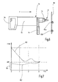
- Fig. 6 shows in greatly simplified form a side view of a drill 70, which can be used to drive the drilling tool 10.
- the drill 70 is a hand-held drill.
- a user can handle the drill 70 without having to fix it on a drilling rig or the like.
- the drilling machine 70 has a drive unit 72, such as an electric motor.
- the drive unit 72 is coupled to a tool holder 74, for example a quick-action receptacle.
- the drilling tool 10 can be accommodated and fixed for rotational drive.
- the drilling machine 70 may further comprise at least one handle 76, 78, preferably two handles.
- the drilling machine 70 with the drilling tool 10 received thereon is particularly suitable for introducing flow bores into a workpiece 80, which are at least partially reshaping and at least partially machined.
- a flow bore 82a is indicated in the workpiece 80, in which a bead is completely pushed onto the side of the workpiece 80 facing away from the drill 70.
- the flow bore 82b illustrates a hole in the workpiece 80 in which a bead or a collar is formed on both sides.
- the flow holes 82a, 82b are advantageously suitable for introducing a thread.
- Fig. 7 shows a diagram showing a relationship between a Bohrfort Vietnamese and a required feed force or contact force, see. an arrow labeled F in FIG Fig. 6 ,
- the abscissa illustrates a timing of a bore.
- the duration of a hole corresponds to a drilling progress, such as with a penetration depth or a hole diameter achieved.
- required handling forces are applied.
- a graph labeled 100 illustrates required handling forces in a prior art fluid drill.
- a graph labeled 102 illustrates required feed forces or forces on a drilling tool 10 having various elements discussed in the foregoing description. In each case, a core hole with the same diameter was produced in the measurements on which graphs 100 and 102 were based.
- An inventive drilling tool allows a sufficient reduction of the feed force, so that in particular in an initial phase of a flow bore manual feed is possible.
- a corresponding force range is denoted by 104.
Landscapes
- Engineering & Computer Science (AREA)
- Mechanical Engineering (AREA)
- Drilling Tools (AREA)
Applications Claiming Priority (1)
| Application Number | Priority Date | Filing Date | Title |
|---|---|---|---|
| DE102012108481.5A DE102012108481A1 (de) | 2012-09-11 | 2012-09-11 | Bohrwerkzeug sowie Verwendung eines Bohrwerkzeugs |
Publications (3)
| Publication Number | Publication Date |
|---|---|
| EP2705916A2 true EP2705916A2 (fr) | 2014-03-12 |
| EP2705916A3 EP2705916A3 (fr) | 2016-08-24 |
| EP2705916B1 EP2705916B1 (fr) | 2020-04-08 |
Family
ID=49080746
Family Applications (1)
| Application Number | Title | Priority Date | Filing Date |
|---|---|---|---|
| EP13182348.6A Active EP2705916B1 (fr) | 2012-09-11 | 2013-08-30 | Outil de perçage et utilisation d'un outil de perçage |
Country Status (2)
| Country | Link |
|---|---|
| EP (1) | EP2705916B1 (fr) |
| DE (1) | DE102012108481A1 (fr) |
Families Citing this family (2)
| Publication number | Priority date | Publication date | Assignee | Title |
|---|---|---|---|---|
| DE102014205065A1 (de) * | 2014-03-19 | 2015-09-24 | Bayerische Motoren Werke Aktiengesellschaft | Einseitiges Vorloch-Durchstoßfügen |
| DE102021207261A1 (de) | 2021-07-09 | 2023-01-12 | Siemens Mobility GmbH | Verfahren zum Anbringen einer Messeinrichtung an einem Rohr |
Citations (1)
| Publication number | Priority date | Publication date | Assignee | Title |
|---|---|---|---|---|
| EP0150518A1 (fr) | 1984-01-30 | 1985-08-07 | Flowdrill B.V. | Outil de perçage par fluage, notamment pour une machine de perçage à main |
Family Cites Families (2)
| Publication number | Priority date | Publication date | Assignee | Title |
|---|---|---|---|---|
| GB2091610B (en) * | 1981-01-21 | 1984-06-27 | Hiby Friedrich Karl | Flow drilling tools |
| EP0072280B1 (fr) * | 1981-07-24 | 1985-03-13 | Emuge-Werk Richard Glimpel Fabrik für Präzisionswerkzeuge (vormals Moschkau & Glimpel) | Taraud pour taraudages de grande précision |
-
2012
- 2012-09-11 DE DE102012108481.5A patent/DE102012108481A1/de not_active Ceased
-
2013
- 2013-08-30 EP EP13182348.6A patent/EP2705916B1/fr active Active
Patent Citations (1)
| Publication number | Priority date | Publication date | Assignee | Title |
|---|---|---|---|---|
| EP0150518A1 (fr) | 1984-01-30 | 1985-08-07 | Flowdrill B.V. | Outil de perçage par fluage, notamment pour une machine de perçage à main |
Also Published As
| Publication number | Publication date |
|---|---|
| EP2705916B1 (fr) | 2020-04-08 |
| EP2705916A3 (fr) | 2016-08-24 |
| DE102012108481A1 (de) | 2014-03-13 |
Similar Documents
| Publication | Publication Date | Title |
|---|---|---|
| EP1409185B1 (fr) | Outil de formage de filet ou taraud | |
| DE3751009T2 (de) | Selbstzentrierendes bohrwerkzeug mit pilotschneidteil. | |
| CN1046017C (zh) | 具有流动成型段的自钻和螺纹成型钻头 | |
| EP0464071B1 (fr) | Vis autotaraudeuse | |
| DE60221252T2 (de) | Selbstpolierende und selbstschneidende nietanordnung | |
| EP1616652B1 (fr) | Outil pour le finissage sans enlèvement de copeaux d'un taraudage préformé, procédé de fabrication de cet outil et procéde de réalisation d'un taraudage | |
| DE102010006796B4 (de) | Verfahren zur Herstellung eines Bohrers, sowie Bohrer | |
| EP0891238B1 (fr) | Outil de percage pour machines-outils et procede permettant de la produire | |
| DE2811567A1 (de) | Bohrschraube sowie verfahren und vorrichtung zu ihrer herstellung | |
| EP3458217B1 (fr) | Outil de chanfreinage arrière | |
| EP3204180B1 (fr) | Outil de perçage, en particulier alésoir | |
| DE20204848U1 (de) | Auswechselbare Bohrerspitze und Bohrwerkzeuganordnung | |
| EP2705916B1 (fr) | Outil de perçage et utilisation d'un outil de perçage | |
| DE102004013640A1 (de) | Werkzeug und Vorrichtung zur Herstellung von Gewindelöchern | |
| DE10321670A1 (de) | Werkzeug, Vorrichtung und Verfahren zum Entgraten von Bohrungen | |
| EP2969344A1 (fr) | Outil de perçage, en particulier alésoir | |
| DE102009039170B4 (de) | Bohrwerkzeug | |
| EP2915613B1 (fr) | Foret à trou transversal | |
| DE102019200829B4 (de) | Rotations-Werkzeug zur Erzeugung eines Honfreigangs | |
| DE102008027945A1 (de) | Rotierendes spanabtragendes Werkzeug | |
| DE10338754B4 (de) | Werkzeug zur spanlosen Erzeugung eines Gewindes und Verfahren zur Herstellung eines Werkzeugs zur spanlosen Gewindeerzeugung | |
| EP1567293B1 (fr) | Procede de production d'outils de percage | |
| WO2020002581A1 (fr) | Foret étagé | |
| DE19548199A1 (de) | Verfahren zur Herstellung einer Gewindebohrung sowie Werkzeug zur Durchführung eines solchen Verfahrens | |
| DE102021129556B4 (de) | Hybrid-gewindeschneider mit reibahle und gewindeschneidabschnitt |
Legal Events
| Date | Code | Title | Description |
|---|---|---|---|
| PUAI | Public reference made under article 153(3) epc to a published international application that has entered the european phase |
Free format text: ORIGINAL CODE: 0009012 |
|
| AK | Designated contracting states |
Kind code of ref document: A2 Designated state(s): AL AT BE BG CH CY CZ DE DK EE ES FI FR GB GR HR HU IE IS IT LI LT LU LV MC MK MT NL NO PL PT RO RS SE SI SK SM TR |
|
| AX | Request for extension of the european patent |
Extension state: BA ME |
|
| PUAL | Search report despatched |
Free format text: ORIGINAL CODE: 0009013 |
|
| AK | Designated contracting states |
Kind code of ref document: A3 Designated state(s): AL AT BE BG CH CY CZ DE DK EE ES FI FR GB GR HR HU IE IS IT LI LT LU LV MC MK MT NL NO PL PT RO RS SE SI SK SM TR |
|
| AX | Request for extension of the european patent |
Extension state: BA ME |
|
| RIC1 | Information provided on ipc code assigned before grant |
Ipc: B21J 5/06 20060101ALI20160719BHEP Ipc: B23B 51/08 20060101AFI20160719BHEP |
|
| STAA | Information on the status of an ep patent application or granted ep patent |
Free format text: STATUS: REQUEST FOR EXAMINATION WAS MADE |
|
| 17P | Request for examination filed |
Effective date: 20170223 |
|
| RBV | Designated contracting states (corrected) |
Designated state(s): AL AT BE BG CH CY CZ DE DK EE ES FI FR GB GR HR HU IE IS IT LI LT LU LV MC MK MT NL NO PL PT RO RS SE SI SK SM TR |
|
| GRAP | Despatch of communication of intention to grant a patent |
Free format text: ORIGINAL CODE: EPIDOSNIGR1 |
|
| STAA | Information on the status of an ep patent application or granted ep patent |
Free format text: STATUS: GRANT OF PATENT IS INTENDED |
|
| INTG | Intention to grant announced |
Effective date: 20190605 |
|
| GRAS | Grant fee paid |
Free format text: ORIGINAL CODE: EPIDOSNIGR3 |
|
| GRAA | (expected) grant |
Free format text: ORIGINAL CODE: 0009210 |
|
| STAA | Information on the status of an ep patent application or granted ep patent |
Free format text: STATUS: THE PATENT HAS BEEN GRANTED |
|
| RAP1 | Party data changed (applicant data changed or rights of an application transferred) |
Owner name: ATILA GMBH Owner name: DHH GEBAEUDESERVICE UG |
|
| AK | Designated contracting states |
Kind code of ref document: B1 Designated state(s): AL AT BE BG CH CY CZ DE DK EE ES FI FR GB GR HR HU IE IS IT LI LT LU LV MC MK MT NL NO PL PT RO RS SE SI SK SM TR |
|
| REG | Reference to a national code |
Ref country code: CH Ref legal event code: EP Ref country code: AT Ref legal event code: REF Ref document number: 1253695 Country of ref document: AT Kind code of ref document: T Effective date: 20200415 |
|
| REG | Reference to a national code |
Ref country code: IE Ref legal event code: FG4D Free format text: LANGUAGE OF EP DOCUMENT: GERMAN |
|
| REG | Reference to a national code |
Ref country code: DE Ref legal event code: R096 Ref document number: 502013014551 Country of ref document: DE |
|
| REG | Reference to a national code |
Ref country code: NL Ref legal event code: MP Effective date: 20200408 |
|
| REG | Reference to a national code |
Ref country code: LT Ref legal event code: MG4D |
|
| PG25 | Lapsed in a contracting state [announced via postgrant information from national office to epo] |
Ref country code: LT Free format text: LAPSE BECAUSE OF FAILURE TO SUBMIT A TRANSLATION OF THE DESCRIPTION OR TO PAY THE FEE WITHIN THE PRESCRIBED TIME-LIMIT Effective date: 20200408 Ref country code: NL Free format text: LAPSE BECAUSE OF FAILURE TO SUBMIT A TRANSLATION OF THE DESCRIPTION OR TO PAY THE FEE WITHIN THE PRESCRIBED TIME-LIMIT Effective date: 20200408 Ref country code: GR Free format text: LAPSE BECAUSE OF FAILURE TO SUBMIT A TRANSLATION OF THE DESCRIPTION OR TO PAY THE FEE WITHIN THE PRESCRIBED TIME-LIMIT Effective date: 20200709 Ref country code: NO Free format text: LAPSE BECAUSE OF FAILURE TO SUBMIT A TRANSLATION OF THE DESCRIPTION OR TO PAY THE FEE WITHIN THE PRESCRIBED TIME-LIMIT Effective date: 20200708 Ref country code: FI Free format text: LAPSE BECAUSE OF FAILURE TO SUBMIT A TRANSLATION OF THE DESCRIPTION OR TO PAY THE FEE WITHIN THE PRESCRIBED TIME-LIMIT Effective date: 20200408 Ref country code: PT Free format text: LAPSE BECAUSE OF FAILURE TO SUBMIT A TRANSLATION OF THE DESCRIPTION OR TO PAY THE FEE WITHIN THE PRESCRIBED TIME-LIMIT Effective date: 20200817 Ref country code: IS Free format text: LAPSE BECAUSE OF FAILURE TO SUBMIT A TRANSLATION OF THE DESCRIPTION OR TO PAY THE FEE WITHIN THE PRESCRIBED TIME-LIMIT Effective date: 20200808 Ref country code: SE Free format text: LAPSE BECAUSE OF FAILURE TO SUBMIT A TRANSLATION OF THE DESCRIPTION OR TO PAY THE FEE WITHIN THE PRESCRIBED TIME-LIMIT Effective date: 20200408 |
|
| PG25 | Lapsed in a contracting state [announced via postgrant information from national office to epo] |
Ref country code: HR Free format text: LAPSE BECAUSE OF FAILURE TO SUBMIT A TRANSLATION OF THE DESCRIPTION OR TO PAY THE FEE WITHIN THE PRESCRIBED TIME-LIMIT Effective date: 20200408 Ref country code: BG Free format text: LAPSE BECAUSE OF FAILURE TO SUBMIT A TRANSLATION OF THE DESCRIPTION OR TO PAY THE FEE WITHIN THE PRESCRIBED TIME-LIMIT Effective date: 20200708 Ref country code: LV Free format text: LAPSE BECAUSE OF FAILURE TO SUBMIT A TRANSLATION OF THE DESCRIPTION OR TO PAY THE FEE WITHIN THE PRESCRIBED TIME-LIMIT Effective date: 20200408 Ref country code: RS Free format text: LAPSE BECAUSE OF FAILURE TO SUBMIT A TRANSLATION OF THE DESCRIPTION OR TO PAY THE FEE WITHIN THE PRESCRIBED TIME-LIMIT Effective date: 20200408 |
|
| PG25 | Lapsed in a contracting state [announced via postgrant information from national office to epo] |
Ref country code: AL Free format text: LAPSE BECAUSE OF FAILURE TO SUBMIT A TRANSLATION OF THE DESCRIPTION OR TO PAY THE FEE WITHIN THE PRESCRIBED TIME-LIMIT Effective date: 20200408 |
|
| REG | Reference to a national code |
Ref country code: DE Ref legal event code: R097 Ref document number: 502013014551 Country of ref document: DE |
|
| PG25 | Lapsed in a contracting state [announced via postgrant information from national office to epo] |
Ref country code: SM Free format text: LAPSE BECAUSE OF FAILURE TO SUBMIT A TRANSLATION OF THE DESCRIPTION OR TO PAY THE FEE WITHIN THE PRESCRIBED TIME-LIMIT Effective date: 20200408 Ref country code: EE Free format text: LAPSE BECAUSE OF FAILURE TO SUBMIT A TRANSLATION OF THE DESCRIPTION OR TO PAY THE FEE WITHIN THE PRESCRIBED TIME-LIMIT Effective date: 20200408 Ref country code: CZ Free format text: LAPSE BECAUSE OF FAILURE TO SUBMIT A TRANSLATION OF THE DESCRIPTION OR TO PAY THE FEE WITHIN THE PRESCRIBED TIME-LIMIT Effective date: 20200408 Ref country code: RO Free format text: LAPSE BECAUSE OF FAILURE TO SUBMIT A TRANSLATION OF THE DESCRIPTION OR TO PAY THE FEE WITHIN THE PRESCRIBED TIME-LIMIT Effective date: 20200408 Ref country code: ES Free format text: LAPSE BECAUSE OF FAILURE TO SUBMIT A TRANSLATION OF THE DESCRIPTION OR TO PAY THE FEE WITHIN THE PRESCRIBED TIME-LIMIT Effective date: 20200408 Ref country code: DK Free format text: LAPSE BECAUSE OF FAILURE TO SUBMIT A TRANSLATION OF THE DESCRIPTION OR TO PAY THE FEE WITHIN THE PRESCRIBED TIME-LIMIT Effective date: 20200408 Ref country code: IT Free format text: LAPSE BECAUSE OF FAILURE TO SUBMIT A TRANSLATION OF THE DESCRIPTION OR TO PAY THE FEE WITHIN THE PRESCRIBED TIME-LIMIT Effective date: 20200408 |
|
| PLBE | No opposition filed within time limit |
Free format text: ORIGINAL CODE: 0009261 |
|
| STAA | Information on the status of an ep patent application or granted ep patent |
Free format text: STATUS: NO OPPOSITION FILED WITHIN TIME LIMIT |
|
| PG25 | Lapsed in a contracting state [announced via postgrant information from national office to epo] |
Ref country code: SK Free format text: LAPSE BECAUSE OF FAILURE TO SUBMIT A TRANSLATION OF THE DESCRIPTION OR TO PAY THE FEE WITHIN THE PRESCRIBED TIME-LIMIT Effective date: 20200408 Ref country code: PL Free format text: LAPSE BECAUSE OF FAILURE TO SUBMIT A TRANSLATION OF THE DESCRIPTION OR TO PAY THE FEE WITHIN THE PRESCRIBED TIME-LIMIT Effective date: 20200408 |
|
| REG | Reference to a national code |
Ref country code: DE Ref legal event code: R119 Ref document number: 502013014551 Country of ref document: DE |
|
| 26N | No opposition filed |
Effective date: 20210112 |
|
| PG25 | Lapsed in a contracting state [announced via postgrant information from national office to epo] |
Ref country code: MC Free format text: LAPSE BECAUSE OF FAILURE TO SUBMIT A TRANSLATION OF THE DESCRIPTION OR TO PAY THE FEE WITHIN THE PRESCRIBED TIME-LIMIT Effective date: 20200408 |
|
| REG | Reference to a national code |
Ref country code: CH Ref legal event code: PL |
|
| REG | Reference to a national code |
Ref country code: DE Ref legal event code: R081 Ref document number: 502013014551 Country of ref document: DE Owner name: DHH GEBAEUDESERVICE UG, DE Free format text: FORMER OWNERS: ATILA GMBH, 74933 NEIDENSTEIN, DE; DHH GEBAEUDESERVICE UG, 74869 SCHWARZACH, DE Ref country code: DE Ref legal event code: R081 Ref document number: 502013014551 Country of ref document: DE Owner name: WUNDERFABRIK GMBH, DE Free format text: FORMER OWNERS: ATILA GMBH, 74933 NEIDENSTEIN, DE; DHH GEBAEUDESERVICE UG, 74869 SCHWARZACH, DE |
|
| GBPC | Gb: european patent ceased through non-payment of renewal fee |
Effective date: 20200830 |
|
| PG25 | Lapsed in a contracting state [announced via postgrant information from national office to epo] |
Ref country code: LI Free format text: LAPSE BECAUSE OF NON-PAYMENT OF DUE FEES Effective date: 20200831 Ref country code: CH Free format text: LAPSE BECAUSE OF NON-PAYMENT OF DUE FEES Effective date: 20200831 Ref country code: LU Free format text: LAPSE BECAUSE OF NON-PAYMENT OF DUE FEES Effective date: 20200830 |
|
| REG | Reference to a national code |
Ref country code: BE Ref legal event code: MM Effective date: 20200831 |
|
| PG25 | Lapsed in a contracting state [announced via postgrant information from national office to epo] |
Ref country code: SI Free format text: LAPSE BECAUSE OF FAILURE TO SUBMIT A TRANSLATION OF THE DESCRIPTION OR TO PAY THE FEE WITHIN THE PRESCRIBED TIME-LIMIT Effective date: 20200408 |
|
| PG25 | Lapsed in a contracting state [announced via postgrant information from national office to epo] |
Ref country code: DE Free format text: LAPSE BECAUSE OF NON-PAYMENT OF DUE FEES Effective date: 20210302 Ref country code: FR Free format text: LAPSE BECAUSE OF NON-PAYMENT OF DUE FEES Effective date: 20200831 |
|
| PG25 | Lapsed in a contracting state [announced via postgrant information from national office to epo] |
Ref country code: BE Free format text: LAPSE BECAUSE OF NON-PAYMENT OF DUE FEES Effective date: 20200831 Ref country code: GB Free format text: LAPSE BECAUSE OF NON-PAYMENT OF DUE FEES Effective date: 20200830 Ref country code: IE Free format text: LAPSE BECAUSE OF NON-PAYMENT OF DUE FEES Effective date: 20200830 |
|
| REG | Reference to a national code |
Ref country code: AT Ref legal event code: MM01 Ref document number: 1253695 Country of ref document: AT Kind code of ref document: T Effective date: 20200830 |
|
| PG25 | Lapsed in a contracting state [announced via postgrant information from national office to epo] |
Ref country code: AT Free format text: LAPSE BECAUSE OF NON-PAYMENT OF DUE FEES Effective date: 20200830 |
|
| PG25 | Lapsed in a contracting state [announced via postgrant information from national office to epo] |
Ref country code: TR Free format text: LAPSE BECAUSE OF FAILURE TO SUBMIT A TRANSLATION OF THE DESCRIPTION OR TO PAY THE FEE WITHIN THE PRESCRIBED TIME-LIMIT Effective date: 20200408 Ref country code: MT Free format text: LAPSE BECAUSE OF FAILURE TO SUBMIT A TRANSLATION OF THE DESCRIPTION OR TO PAY THE FEE WITHIN THE PRESCRIBED TIME-LIMIT Effective date: 20200408 Ref country code: CY Free format text: LAPSE BECAUSE OF FAILURE TO SUBMIT A TRANSLATION OF THE DESCRIPTION OR TO PAY THE FEE WITHIN THE PRESCRIBED TIME-LIMIT Effective date: 20200408 |
|
| PG25 | Lapsed in a contracting state [announced via postgrant information from national office to epo] |
Ref country code: MK Free format text: LAPSE BECAUSE OF FAILURE TO SUBMIT A TRANSLATION OF THE DESCRIPTION OR TO PAY THE FEE WITHIN THE PRESCRIBED TIME-LIMIT Effective date: 20200408 |