EP2705917A2 - Outil de fraisage et plaquette de coupe pour un tel outil - Google Patents
Outil de fraisage et plaquette de coupe pour un tel outil Download PDFInfo
- Publication number
- EP2705917A2 EP2705917A2 EP13174718.0A EP13174718A EP2705917A2 EP 2705917 A2 EP2705917 A2 EP 2705917A2 EP 13174718 A EP13174718 A EP 13174718A EP 2705917 A2 EP2705917 A2 EP 2705917A2
- Authority
- EP
- European Patent Office
- Prior art keywords
- milling insert
- cutting edge
- milling
- width
- angle
- Prior art date
- Legal status (The legal status is an assumption and is not a legal conclusion. Google has not performed a legal analysis and makes no representation as to the accuracy of the status listed.)
- Granted
Links
Images





Classifications
-
- B—PERFORMING OPERATIONS; TRANSPORTING
- B23—MACHINE TOOLS; METAL-WORKING NOT OTHERWISE PROVIDED FOR
- B23C—MILLING
- B23C5/00—Milling-cutters
- B23C5/16—Milling-cutters characterised by physical features other than shape
- B23C5/20—Milling-cutters characterised by physical features other than shape with removable cutter bits or teeth or cutting inserts
-
- B—PERFORMING OPERATIONS; TRANSPORTING
- B23—MACHINE TOOLS; METAL-WORKING NOT OTHERWISE PROVIDED FOR
- B23C—MILLING
- B23C5/00—Milling-cutters
- B23C5/16—Milling-cutters characterised by physical features other than shape
- B23C5/20—Milling-cutters characterised by physical features other than shape with removable cutter bits or teeth or cutting inserts
- B23C5/22—Securing arrangements for bits or teeth or cutting inserts
- B23C5/2204—Securing arrangements for bits or teeth or cutting inserts with cutting inserts clamped against the walls of the recess in the cutter body by a clamping member acting upon the wall of a hole in the insert
-
- B—PERFORMING OPERATIONS; TRANSPORTING
- B23—MACHINE TOOLS; METAL-WORKING NOT OTHERWISE PROVIDED FOR
- B23C—MILLING
- B23C5/00—Milling-cutters
- B23C5/16—Milling-cutters characterised by physical features other than shape
- B23C5/20—Milling-cutters characterised by physical features other than shape with removable cutter bits or teeth or cutting inserts
- B23C5/202—Plate-like cutting inserts with special form
- B23C5/205—Plate-like cutting inserts with special form characterised by chip-breakers of special form
-
- B—PERFORMING OPERATIONS; TRANSPORTING
- B23—MACHINE TOOLS; METAL-WORKING NOT OTHERWISE PROVIDED FOR
- B23C—MILLING
- B23C5/00—Milling-cutters
- B23C5/02—Milling-cutters characterised by the shape of the cutter
- B23C5/06—Face-milling cutters, i.e. having only or primarily a substantially flat cutting surface
-
- B—PERFORMING OPERATIONS; TRANSPORTING
- B23—MACHINE TOOLS; METAL-WORKING NOT OTHERWISE PROVIDED FOR
- B23C—MILLING
- B23C5/00—Milling-cutters
- B23C5/16—Milling-cutters characterised by physical features other than shape
- B23C5/20—Milling-cutters characterised by physical features other than shape with removable cutter bits or teeth or cutting inserts
- B23C5/202—Plate-like cutting inserts with special form
-
- B—PERFORMING OPERATIONS; TRANSPORTING
- B23—MACHINE TOOLS; METAL-WORKING NOT OTHERWISE PROVIDED FOR
- B23C—MILLING
- B23C2200/00—Details of milling cutting inserts
- B23C2200/04—Overall shape
- B23C2200/045—Round
-
- B—PERFORMING OPERATIONS; TRANSPORTING
- B23—MACHINE TOOLS; METAL-WORKING NOT OTHERWISE PROVIDED FOR
- B23C—MILLING
- B23C2200/00—Details of milling cutting inserts
- B23C2200/08—Rake or top surfaces
- B23C2200/081—Rake or top surfaces with projections
-
- B—PERFORMING OPERATIONS; TRANSPORTING
- B23—MACHINE TOOLS; METAL-WORKING NOT OTHERWISE PROVIDED FOR
- B23C—MILLING
- B23C2200/00—Details of milling cutting inserts
- B23C2200/12—Side or flank surfaces
- B23C2200/125—Side or flank surfaces discontinuous
-
- B—PERFORMING OPERATIONS; TRANSPORTING
- B23—MACHINE TOOLS; METAL-WORKING NOT OTHERWISE PROVIDED FOR
- B23C—MILLING
- B23C2200/00—Details of milling cutting inserts
- B23C2200/16—Supporting or bottom surfaces
- B23C2200/164—Supporting or bottom surfaces discontinuous
-
- B—PERFORMING OPERATIONS; TRANSPORTING
- B23—MACHINE TOOLS; METAL-WORKING NOT OTHERWISE PROVIDED FOR
- B23C—MILLING
- B23C2200/00—Details of milling cutting inserts
- B23C2200/16—Supporting or bottom surfaces
- B23C2200/168—Supporting or bottom surfaces with features related to indexing
-
- B—PERFORMING OPERATIONS; TRANSPORTING
- B23—MACHINE TOOLS; METAL-WORKING NOT OTHERWISE PROVIDED FOR
- B23C—MILLING
- B23C2200/00—Details of milling cutting inserts
- B23C2200/20—Top or side views of the cutting edge
- B23C2200/208—Wiper, i.e. an auxiliary cutting edge to improve surface finish
-
- B—PERFORMING OPERATIONS; TRANSPORTING
- B23—MACHINE TOOLS; METAL-WORKING NOT OTHERWISE PROVIDED FOR
- B23C—MILLING
- B23C2200/00—Details of milling cutting inserts
- B23C2200/24—Cross section of the cutting edge
- B23C2200/243—Cross section of the cutting edge bevelled or chamfered
-
- B—PERFORMING OPERATIONS; TRANSPORTING
- B23—MACHINE TOOLS; METAL-WORKING NOT OTHERWISE PROVIDED FOR
- B23C—MILLING
- B23C2200/00—Details of milling cutting inserts
- B23C2200/28—Angles
- B23C2200/287—Positive rake angles
-
- B—PERFORMING OPERATIONS; TRANSPORTING
- B23—MACHINE TOOLS; METAL-WORKING NOT OTHERWISE PROVIDED FOR
- B23C—MILLING
- B23C2210/00—Details of milling cutters
- B23C2210/16—Fixation of inserts or cutting bits in the tool
- B23C2210/168—Seats for cutting inserts, supports for replacable cutting bits
-
- B—PERFORMING OPERATIONS; TRANSPORTING
- B23—MACHINE TOOLS; METAL-WORKING NOT OTHERWISE PROVIDED FOR
- B23C—MILLING
- B23C2210/00—Details of milling cutters
- B23C2210/28—Arrangement of teeth
- B23C2210/282—Unequal angles between the cutting edges, i.e. cutting edges unequally spaced in the circumferential direction
-
- B—PERFORMING OPERATIONS; TRANSPORTING
- B23—MACHINE TOOLS; METAL-WORKING NOT OTHERWISE PROVIDED FOR
- B23C—MILLING
- B23C2210/00—Details of milling cutters
- B23C2210/66—Markings, i.e. symbols or indicating marks
Definitions
- this invention relates to a milling tool of the type that comprises on one hand a basic body having front and rear ends, between which there extend an envelope surface and a centre axis on which the basic body is rotatable, and on the other hand a plurality of single sided and indexable milling inserts having a round basic shape, which individually comprise an upper side, an under side, and a clearance surface that extends between the same and, at least closest to the upper side, converges toward the under side in order to provide a positive cutting geometry of a cutting edge positioned between the clearance surface and a chip surface included in the upper side, which cutting edge includes a reinforcing chamfer surface that is delimited against the clearance surface via an outer boundary line and against the chip surface via an inner boundary line, the situation of the upper and under sides in the milling insert being defined by upper and lower reference planes, each one of which extends perpendicular to a centre axis of an imaginary cylinder that circumscribes the periphery of the upper side and thereby
- the invention in addition to a milling insert as such, viz. a single sided, indexable milling insert having a round basic shape.
- Round milling inserts for milling purposes have the advantage in comparison with polygonal milling inserts having straight cutting edges in that they lack fragile corners. For this reason, the same are advantageously used in applications where the milling cutter should be able to mill off or remove large amounts of material from the workpiece without considerable requirements of surface smoothness of the generated surface.
- the fact that the round milling inserts as a consequence of their arched cutting edges giving rise to wave formations in the generated surface is accordingly incidental in comparison with the capacity of the milling inserts to remove deep material layers from the workpiece.
- Round milling inserts are found in single sided as well as double-sided embodiments, the first-mentioned ones of which are formed with cutting edges only along the upper sides and therefore can be given a positive insert macro geometry, while the insert macro geometry of the last-mentioned ones is negative as a consequence of cutting edges being formed along the upper side as well as the under side.
- the invention only concerns itself with the first-mentioned type of milling inserts, i.e., single sided, indexable milling inserts having a round basic shape and positive insert macro geometry.
- milling inserts having a positive insert macro geometry are more easy-cutting, concerning generated cutting force, than double-sided, negative milling inserts because the cutting edge is introduced under the chip so as to, like a knife or wedge, lift out and cut the chip rather than pushing the same in front of itself during shearing.
- single sided, round milling inserts are subjected to considerable cutting forces, among other things as a consequence of the chip obtaining an increasing thickness with increasing cutting depths. From a narrow end, the thickness of the chip increases to a maximum value, the absolute value of which depends on several factors, but above all the feed rate of the milling cutter per milling insert in the milling cutter body.
- the same is usually formed with a chamfer surface in the transition between the clearance surface and the chip surface.
- said reinforcing chamfer surface is of a uniform width along the entire periphery of the upper side (i.e., 360°). See, for instance, US 2009/0290946 A1 .
- This means that the cutting edge along its entire operative arc length has one and the same geometry and strength irrespective of cutting depth and thereby irrespective of the shape of the generated chips.
- the cutting edge is as obtuse in the area where the chip is thin, as in the area where the same is thick.
- a primary object of the invention is to provide a milling insert that is as easy-cutting as possible and the cutting edge of which, in an operative state, is optimized in view of the nature of the generated chip. Another object is to provide a milling insert that works well for small as well as great cutting depths up to a recommended maximum depth.
- the milling insert being formed with a plurality of tangentially spaced-apart cutting edges, which individually fall archedly from a first end, situated closest to the reference plane of the upper side, to a lowest point, from which it rises toward a second end, besides which the inner boundary line of the chamfer surface diverges from the outer one so as to give the chamfer surface an increasing width in the direction from the first end of the cutting edge toward the second end thereof.
- the milling insert becomes easy-cutting on one hand as a consequence of the arc-shape of the cutting edge as viewed laterally (the cutting edge will because of this design carve into the material), and on the other hand as a consequence of the cutting edge being comparatively narrow and sharp in the area where the cutting depth is small and the chip narrow, but more obtuse and stronger with increasing cutting depth when the chip is thick, more precisely as a consequence of the increasing width of the chamfer surface from one end of the cutting edge toward the other.
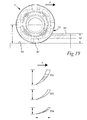
- Fig. 19 illustrates the milling insert according to the invention during operation.
- S1 designates an unmachined surface of a workpiece
- S2 designates the generated surface that is left after the chip removal.
- the arrow F indicates the feeding direction of the milling cutter
- a p designates the cutting depth in question.
- the individual cutting edge of the milling insert may form a chip removing main edge, which at its first end transforms into a wiper edge, which - when the milling insert is viewed in plane elevation toward the upper side - has a radius that is greater than the radius of the main edge, such as this is determined by the outer boundary line of the chamfer surface.
- a wiper edge the radius of which may approach ⁇
- a surface-wiping effect is obtained along the generated surface S2.
- the milling tool can be used not only for the removal of large quantities of material from the workpiece, but also for providing a good surface finish of the generated surface.
- a versatile useful milling tool is provided, which may be utilized also in face milling operations, where requirements of surface finish are present.
- the milling insert may be formed so that the nominal clearance angle thereof along the cutting edge decreases in the direction from the first end thereof - where the chamfer surface has its smallest width -toward the second end thereof. In such a way, an approximately uniform functional clearance is obtained against the workpiece, along the active arc length of the cutting edge, independently of the cutting depth.
- the nominal rake angle of the cutting edge increases in the direction from the first end toward the second one.
- the rake angle becomes greater (a person skilled in the art would say "more positive") toward the strongest portion of the cutting edge, i.e., where the chamfer surface has its greatest width.
- the width of the chamfer surface is large, a satisfactory cutting edge strength is obtained, which decreases the need of a small rake angle, for the purpose of providing a durable cutting edge, and therefore a greater, more positive rake angle can be used to reduce the generated cutting force.
- the cutting edge angle of the cutting edge - such as this is defined by the angle between the chip surface and the clearance surface in arbitrary sections along the cutting edge - may decrease in the direction from the first end of the cutting edge toward the second end thereof so as to, in such a way, combine the effects of the above-mentioned reduction of the clearance angle and the increase of the rake angle of the cutting edge.
- the individual chamfer surface may include two part surfaces that are separated by a dividing line from which the outer boundary line as well as the inner one diverges in the direction from the first end of the cutting edge toward the second one. In such a way, the chip removal is facilitated also along those segments of the cutting edge where the chamfer surface has its greatest total width.
- This embodiment entails the good effect that the cutting forces (and to a certain extent the generation of heat) are reduced in comparison with the feasible embodiment that makes use of a single, continuous chamfer surface.
- the chamfer surface included in the cutting edge may have a greatest width that is at least twice as large as its smallest width. In such a way, a good strength is guaranteed of the most exposed portion of the cutting edge.
- the outer part surface thereof When the chamfer surface is broken, the outer part surface thereof may have a width that in a section closest to the first end of the cutting edge is greater than the width of the inner part surface, but that in a section closest to the second end has a width that is smaller than the width of the inner part surface. In such a way, an optimum strength is combined with an optimum chip removal capacity in the different segments of the cutting edge.
- the arc length of the chamfer surface in question may amount to at least 75 % of the total arc length that each cutting edge occupies of the 360° periphery of the upper side.
- the milling insert can operate with a recommended maximum cutting depth that is considerably greater than half of the radius of the milling insert.
- the outer part surface of a broken chamfer surface may have an angle to the upper reference plane that increases in the direction from the first end of the cutting edge toward the second end thereof.
- the lock means which have the purpose of rotationally securing the milling insert in an appurtenant seat in the basic body of the tool, may be a connecting surface that is formed in the under side of the milling insert and includes a plurality of radially oriented ridges and countersinks between the same. Such a connecting surface guarantees that the exact spatial position of the milling insert in relation to the tool body is obtained also after indexings and repeated insert replacements.
- a plurality of tangentially spaced-apart and plane side contact surfaces may be formed in the envelope surface of the individual milling insert.
- the side contact surfaces of the milling insert may advantageously be located in the same radial plane as the ridges of the connecting surface of the milling insert.
- the side contact surfaces may be located in the area under the wiper edges, where the milling insert has its greatest thickness and is strongest. In these areas, also the ends of the individual cutting edge are situated, which means that the side contact surfaces are separated from the lowest point (usually the centre) of the cutting edge, where the flank wear-out is great because of a great thickness of chip.
- a milling tool having a round milling insert, formed in accordance with the invention.
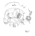
- the tool includes a basic body 1 in the form of a milling cutter head as well as a plurality of milling inserts 2.
- tightening devices in the form of screws 3 are also included, which have the purpose of fixing the milling inserts in a number of seats 4 in the basic body 1.
- the basic body includes front and rear ends, between which a centre axis C1 extends on which the basic body is rotatable. Of the two ends, the front one is designated 5.
- the seats 4 are formed in the peripheral transition between the front end 5 of the basic body and an envelope surface designated 6, which is rotationally symmetrical in respect of the centre axis C1.
- In front of each seat 4 - as viewed in the direction of rotation R - there is also a chip channel 7 for each milling insert.
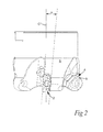
- each individual milling insert 2 is located in a spatial position that is tipped-in in the basic body and determined by two different angles ⁇ and ⁇ , ⁇ of which is the axial tipping-in angle of the milling insert, while ⁇ is the radial tipping-in angle.
- ⁇ is positive so far that the plane thereof leans obliquely upward/rearward in relation to the centre axis C, while the radial tipping-in angle ⁇ is negative.
- ⁇ amounts to approx.
- +5° which by a person skilled in the art is considered as a moderate angle, which entails that the milling insert obtains a good support against a bottom support surface 8 included in the seat 4, without because of this waiving the functional clearance along the active cutting edge of the milling insert.
- ⁇ may vary upward as well as downward. However, the same should not exceed +15°.
- the same may also be moderately negative, i.e., lean obliquely upward/forward in the direction of rotation. However, a possible negative tilt should not be greater than -5 ° or/to -10°.
- the radial tipping-in angle ⁇ should always be negative, i.e., not exceed 0°. In the example, ⁇ amounts to -5°. In practice, ⁇ may vary between 0°and -15°.
- Figs. 5-10 which more in detail illustrate the nature of the milling insert 2.
- Basal features of the milling insert are that the same includes an upper side 9, an under side 10 as well as a circumferential clearance surface 11, which generally is rotationally symmetrical in respect of a centre axis C2, and which extends between the upper and under sides.
- the clearance surface At least closest to the upper side 9, the clearance surface, in its entirety designated 11, converges toward the under side to provide a positive insert macro geometry of a cutting edge, generally designated 12, that in a traditional way is formed in the transition between the upper side and the lateral, endless clearance surface 11.
- Fig. 5-10 Basal features of the milling insert are that the same includes an upper side 9, an under side 10 as well as a circumferential clearance surface 11, which generally is rotationally symmetrical in respect of a centre axis C2, and which extends between the upper and under sides.
- the clearance surface At least closest to the upper side 9, the clearance surface, in its entirety designated 11, converges toward the under side to provide
- the situation of the upper and under sides 9, 10 in the milling insert is defined by upper and lower reference planes designated URP and LRP, respectively. These planes are mutually parallel by extending perpendicular to the centre axis C2.
- the last-mentioned one is a centre axis of an imaginary cylinder CY, which circumscribes the periphery of the upper side and thereby defines the round basic shape of the milling insert.
- the basic body 1 includes totally five seats, which, in order to counteract vibrations in the tool, is placed with a differentiated spacing.
- the pitch angle ⁇ 1 amounts to 73°, ⁇ 2 to 71 °, ⁇ 3 to 72°, ⁇ 4 to 73,5°, and ⁇ 5 to 70,5°.
- the milling insert is formed with a through hole 14, the centre axis of which coincides with the centre axis C2 of the milling insert.
- the milling insert includes lock means for rotationally securing the same in the seat.
- this means is a connecting surface 15 formed in the under side 10 of the milling insert.
- Said connecting surface includes a plurality of ridges 16 that are mutually separated via countersinks or valleys 17, the first-mentioned ones of which form male-like engagement members and the last-mentioned ones female-like ones.
- the ridges 16 as well as the valleys 17 extend radially in the direction from inner ends adjacent to the hole 14 toward outer ends adjacent to a circumferential transition surface 18 between the under side of the milling insert and the clearance surface 11.
- a plurality of, more precisely four, cutting edges 12 are formed, which are tangentially spaced-apart from each other, and each one of which occupies 1 ⁇ 4 of the 360° periphery of the upper side.
- the spacing between the cutting edges amounts in this case to 90°.
- Figs. 11-18 which in more detail illustrate the design of the cutting edge 12.
- Fig. 11 an enlarged, sector-shaped portion of the upper side of the milling insert is shown, more precisely as viewed in plane elevation from above.
- the cutting edge extends between first and second ends 20 and 21, respectively.
- a chamfer surface in its entirety designated 22, is included, which is delimited against the clearance surface 11 via an outer boundary line 23, and against the chip surface 19 via an inner boundary line 24.
- Two primary features characterizes the cutting edge 12, viz. that it falls archedly from the first end 20 to a lowest point or bottom point BP, from which it again rises toward the second end 21, as well as that the inner boundary line 24 of the chamfer surface 22 diverges from the outer one so as to give the chamfer surface an increasing width in the direction from the first end 20 of the cutting edge toward the second end 21.
- the outer boundary line 23 is arched as viewed in plane elevation according to Fig. 11 .
- the boundary line extends archedly between the ends 20, 21 of the cutting edge.
- the boundary line 23 - and thereby the cutting edge 12 as such - is arched in two different co-ordinate directions.
- the cutting edge 12 at its first end 20, transforms into a secondary edge or wiper edge 25, which has the purpose of wiping off or levelling the surface generated during milling.
- the cutting edge 12 forms a main edge, which guarantees the chip removal
- the secondary edge 25 forms a wiper edge having the purpose of wiping off or levelling the generated bottom surface S2 (see Fig. 19 ).
- the secondary edge 25 has an arc length b1 that only constitutes a fraction of the arc length b2 of the main edge 12. Furthermore, the radius r1 of the secondary edge 25 is considerably greater than the radius r2 of the cutting edge 12. The last-mentioned radius r2 amounts essentially to half of the diameter of the milling insert, while r1 in practice may approach ⁇ . In other words, the secondary edge 25 may have an approximately straight shape (however without becoming absolutely straight).
- ⁇ designates a rake angle, i.e., the angle that the chip surface 19 forms with the upper reference plane URP, while ⁇ designates the clearance angle that the clearance surface 11 forms with a vertical reference line or the geometrical cylinder CY.
- the rake angle ⁇ as well as the clearance angle ⁇ varies along the periphery of the milling insert.
- the chamfer surface 22 includes two part surfaces 26, 27 (see Fig. 11 ) that are separated by a dividing line 28 from which the outer boundary line 23 as well as the inner 24 diverge, more precisely in the direction from the first end 20 of the cutting edge toward the second one 21.
- the wiper edge 25 includes a reinforcing chamfer surface 22a, which is broken into two part surfaces 26a, 27a (see Fig. 13b ).
- the section B is situated at the first, narrow end 20 of the cutting edge 12, while the sections C, D and E are located closer to the opposite end 21. More precisely, the section D is placed in the vicinity of the bottom point BP, while the section E is placed closer to the end 21, although spaced apart clockwise from the same.
- the radially outer part surface 26 of the chamfer surface 22 forms (as well as the corresponding part surface 26a along the wiper edge 25) an angle, designated ⁇ , with the reference plane URP. By those skilled in the art, said angle is denominated "negative bevel angle".
- the cutting edge angle ⁇ of the cutting edge - such as this is defined by the angle between the chip surface 19 and the clearance surface 11 - decreases in the direction from the first end 20 toward the second one 21.
- This reduction of the cutting edge angle is commenced in the section B, i.e., at the first end 20 and continues up to and past the section D, i.e., a distance past the lowest situated point BP of the cutting edge.
- Said reduction of the cutting edge angle is, above all, caused by an increase of the rake angle ⁇ , at the same time as the clearance angle ⁇ remains in all essentials constant (between 12° and 13°).
- the outer part surface 26 of the chamfer surface 22 has a width W1, which in sections closest to the first end 20 of the cutting edge is greater than the width W2 of the inner part surface 27. In an area between the sections C and D, however, this relation is altered so far that the width W1 of the outer part surface 26 becomes successively smaller than the width of the inner part surface the closer to the end 21 the sections are situated.
- the chamfer surface has a greatest width W that is approx. ten times greater than its smallest width (cf. the values of the sections B and C). It is true that said relation may vary, but at all events the greatest width should be at least twice as large as the smallest one.
- the chamfer surface has its maximal width in an area between the sections C and D.
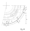
- Fig. 18 it is seen that the arc length b2 of the cutting edge between the ends 20 and 21 occupies the major part of the 90° that each one of the four cutting edges occupies of the 360° periphery of the upper side.
- the cutting edge occupies approx. 90 % of the 90° available.
- the cutting edge 12 transforms into an adjacent wiper edge via a tapering transition portion 30, the geometrical shape of which lacks importance because no chip removal will take place in this part of the milling insert.
- the co-operating wiper edge 25 occupies a certain part of the available 90°. At all events, however, the arc length of the chip removing cutting edge 22 should not be less than 75 % of the available arch.
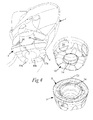
- the bottom surface 8 of the seat 4 forms a connecting surface, which like the connecting surface 15 of the milling insert includes ridges 16a surrounded by valleys 17a.
- These ridges and valleys form male and female, respectively, members arranged to co-operate with the ridges and the valleys in the connecting surface of the milling insert, more precisely in such a way that the individual ridge 16 of the milling insert engages a valley 17a in the connecting surface 8 of the seat, while the ridges 16a of the connecting surface of the seat engage the valleys 17 in the milling insert.
- the two connecting surfaces in this case are essentially ring-shaped and surround the holes 13, 14 in the seat and the milling insert, respectively.
- the connecting surface 8 serving as bottom also two side support surfaces 30 are included in the seat 4, which are plane and intended to co-operate with a pair of plane side contact surfaces 31 of the clearance surface 11 of the milling insert. Because the milling insert includes four cutting edges and should be indexable in four positions, the milling insert includes four such side contact surfaces 31, only two of which - depending on the index position - are kept pressed against the side support surfaces 30. Primarily, the male and female members of the connecting surfaces 8, 15 counteract rotation of the milling insert, while the contact between the side support surfaces 30 and the side contact surfaces 31 has the purpose of relieving the pressure on the tightening screw 3 so that the same is not deformed under load.
- the side contact surfaces 31 of the milling insert have a limited height in order to be housable under the cutting edge that is delimited by the upper portion of the clearance surface 11.
- the side contact surfaces 31 are placed in the same radial plane as the ridges 16 of the connecting surface 15.
- the wiper edge 25 is situated in one and the same radial plane as the ridge and the side contact surface 31, also the wiper edge 25 is situated. The consequence of this is that the side contact surfaces 31 are formed in those portions of the milling insert that have maximum thickness.
- the secondary edges 25 and the connections thereof to the surrounding cutting edges 22 are the highest situated points of the milling insert, which are tangent to the upper reference plane URP.
- the main edges fall in relation to the upper reference plane, and in an analogous way the periphery of the lower connecting surface 15 rises, such as this is represented by the transition surface 18 in the areas that are situated between the ridges 16, i.e., where the valleys 17 are situated.
- the milling insert has its smallest thickness in an area approximately halfway between two side contact surfaces 31.
- Fig. 19 schematically illustrates the function of a milling insert included in the milling tool during operation.
- F designates the feeding direction of the milling cutter.
- the operative cutting edge 22 will remove chips 33a, 33b and 33c, the shape/thickness of which vary depending on the selected cutting depth ap . If the cutting depth is small, the chip (see 33a) will be comparatively thin even if its thickness increases from one end to the other. With an increasing cutting depth, the thickness of the chips (33b, 33c) increase successively up to a maximum thickness that corresponds to a maximum, recommended cutting depth. This recommended maximum depth may, per se, vary in different applications. However, the cutting depth ap should not exceed 2/3 of the radius r of the milling insert.
- OP designates the zero point (situated 6 o'clock) in which the chip removing effect of the cutting edge 22, via the wiper edge 20, transforms into a surface-wiping effect along the generated surface S2.
- the individual cutting edge By forming the individual cutting edge in the way described above, its chip removing capacity is optimized independently of the selected cutting depth. If the cutting depth is small, only the pointed and easy-cutting part of the cutting edge, which is situated closest to the wiper edge, starts to function. In these circumstances, the cutting forces are limited, and therefore said part of the cutting edge is not subjected to any greater cutting forces tending to wear out or damage the milling insert. If the thickness of the chip - as a consequence of an increased cutting depth - increases, the cutting edge is subjected to greater cutting forces, in particular where the cutting depth is greatest and the chip thickest. Also in these circumstances, the cutting edge is durable because the chamfer surface thereof will be wider and wider from the wiper edge toward the upper end of the cutting edge.
- the cutting edge does not lose its easy-cutting capacity because the arched sagging of the cutting edge in relation to the upper reference plane of the milling insert ensures that the functional axial angle of the cutting edge increases, and thereby compensates a moderate axial tipping-in angle.
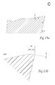
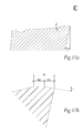
- Figs. 20a and 20b there is illustrated a comparison between a cutting edge, the chamfer surface 22 of which is continuous and a cutting edge having a broken one, i.e., a chamfer surface that - in accordance with the described embodiment - includes two part surfaces 26, 27 oriented at an obtuse angle to each other.
- the chip which is subject to removal, will be folded down in the forward direction from the cutting edge. This means that the cutting forces become greater than in the case that is shown in Fig. 20b .
- the chip will be guided more inward toward the centre of the milling insert (upward in Fig. 20b ). In such a way, the chip will slide easier along the cutting edge, whereby the cutting forces are reduced.
Landscapes
- Engineering & Computer Science (AREA)
- Mechanical Engineering (AREA)
- Milling Processes (AREA)
Applications Claiming Priority (1)
| Application Number | Priority Date | Filing Date | Title |
|---|---|---|---|
| SE1251004A SE536647C2 (sv) | 2012-09-07 | 2012-09-07 | Fräsverktyg jämte skär härför med växelvis användbara skäreggar |
Publications (3)
| Publication Number | Publication Date |
|---|---|
| EP2705917A2 true EP2705917A2 (fr) | 2014-03-12 |
| EP2705917A3 EP2705917A3 (fr) | 2016-02-17 |
| EP2705917B1 EP2705917B1 (fr) | 2017-03-15 |
Family
ID=48700447
Family Applications (1)
| Application Number | Title | Priority Date | Filing Date |
|---|---|---|---|
| EP13174718.0A Active EP2705917B1 (fr) | 2012-09-07 | 2013-07-02 | Plaquette de coupe de fraisage et outil de fraisage avec une telle plaquette |
Country Status (7)
| Country | Link |
|---|---|
| EP (1) | EP2705917B1 (fr) |
| JP (1) | JP6351937B2 (fr) |
| KR (1) | KR102090835B1 (fr) |
| CN (1) | CN103658798B (fr) |
| BR (1) | BR102013022503A2 (fr) |
| RU (1) | RU2630113C2 (fr) |
| SE (1) | SE536647C2 (fr) |
Cited By (5)
| Publication number | Priority date | Publication date | Assignee | Title |
|---|---|---|---|---|
| EP3200944A4 (fr) * | 2014-09-30 | 2018-08-15 | Eip Holdings LLC | Dispositifs de coupe à dents rondes et procédé de conception et d'utilisation |
| US10300539B2 (en) | 2014-06-18 | 2019-05-28 | National University Corporation Nagoya University | Rotating-cutting-edge-type milling tool and cutting method using same |
| CN114147270A (zh) * | 2020-09-07 | 2022-03-08 | 株式会社泰珂洛 | 铣削工具 |
| CN114226819A (zh) * | 2022-01-12 | 2022-03-25 | 百斯图工具制造有限公司 | 一种防转通用圆形铣削刀片 |
| US20220395915A1 (en) * | 2019-10-28 | 2022-12-15 | Korloy Inc. | Cutting insert and cutting tool equipped with the same |
Families Citing this family (12)
| Publication number | Priority date | Publication date | Assignee | Title |
|---|---|---|---|---|
| KR101529524B1 (ko) * | 2014-08-18 | 2015-06-17 | 한국야금 주식회사 | 절삭 인서트 및 이를 장착하는 공구 홀더 |
| EP3351329B1 (fr) * | 2017-01-18 | 2023-08-02 | Sandvik Intellectual Property AB | Insert de découpe et outil de fraisage amovibles |
| US20190084063A1 (en) * | 2017-09-15 | 2019-03-21 | Korloy Inc | Tool for processing engine block and method of processing engine block |
| DE102017122054A1 (de) | 2017-09-22 | 2019-03-28 | Kennametal Inc. | Schneidwerkzeug sowie Verfahren zur Herstellung eines Schneidwerkzeugs |
| EP3530391A1 (fr) * | 2018-02-26 | 2019-08-28 | Seco Tools Ab | Insert de découpe et corps d'outil pour un outil de fraisage |
| CN109226851A (zh) * | 2018-05-09 | 2019-01-18 | 哈尔滨理工大学 | 一种不等齿可转位的环形刀 |
| EP3689522B1 (fr) * | 2019-01-31 | 2023-08-02 | AB Sandvik Coromant | Insert de découpe rond pour outil de fraisage |
| DE102019127027A1 (de) | 2019-10-08 | 2021-04-08 | Kennametal Inc. | Schneidwerkzeug |
| CN111459096B (zh) * | 2020-04-07 | 2023-04-07 | 西南交通大学 | 一种非均匀磨损圆弧头立铣刀的侧铣铣削力计算方法 |
| EP4052823A1 (fr) * | 2021-03-02 | 2022-09-07 | AB Sandvik Coromant | Outil de fraisage de découpe métallique |
| CN113275636A (zh) * | 2021-06-21 | 2021-08-20 | 昆山长鹰硬质材料科技股份有限公司 | 一种圆形刀片及其刀具 |
| CN118875339B (zh) * | 2024-09-29 | 2025-03-14 | 赣州澳克泰工具技术有限公司 | 切削刀片 |
Citations (1)
| Publication number | Priority date | Publication date | Assignee | Title |
|---|---|---|---|---|
| US20090290946A1 (en) | 2006-05-18 | 2009-11-26 | Zastrozynski Jurgen | Cutting insert for machining a workpiece |
Family Cites Families (18)
| Publication number | Priority date | Publication date | Assignee | Title |
|---|---|---|---|---|
| SE459237B (sv) * | 1987-10-26 | 1989-06-19 | Sandvik Ab | Vaendskaer foer planfraesning |
| SE500722C2 (sv) * | 1993-01-27 | 1994-08-15 | Sandvik Ab | Skär med vriden spånyta |
| JPH09207007A (ja) * | 1996-01-31 | 1997-08-12 | Mitsubishi Materials Corp | ホーニング付きスローアウェイチップ |
| JPH09225724A (ja) * | 1996-02-21 | 1997-09-02 | Toshiba Tungaloy Co Ltd | フライス用チップ |
| JP4043080B2 (ja) * | 1997-09-12 | 2008-02-06 | 株式会社タンガロイ | 正面フライス用のスローアウェイチップ |
| DE10006431C1 (de) * | 2000-02-14 | 2001-09-27 | Felix Leeb | Fräs- u. Drehwerkzeug |
| IL153938A0 (en) * | 2003-01-14 | 2003-07-31 | Iscar Ltd | Cutting insert and milling cutter |
| DE10326662A1 (de) * | 2003-06-11 | 2005-01-05 | Sandvik Ab | Schneideinsatz zum Drehen und Fräsen |
| RU2318634C2 (ru) * | 2005-04-13 | 2008-03-10 | Валентин Алексеевич Настасенко | Торцовая режущая, режуще-деформирующая и деформирующая фреза, рабочие пластины к ней и способ их изготовления, способ обработки деформирующей фрезой |
| SE528751C2 (sv) * | 2005-06-27 | 2007-02-06 | Sandvik Intellectual Property | Svarvverktyg och indexerbart svarvskär, samt tillsats för dylika svarvverktyg |
| DE102005032653B3 (de) * | 2005-07-13 | 2006-11-30 | Fette Gmbh | Verfahren zur Herstellung einer formschlüssigen Verbindung zwischen einem Werkzeugeinsatz und einem Werkzeugträger eines rotierenden Werkzeugs |
| US7607867B2 (en) * | 2006-12-15 | 2009-10-27 | Sandvik Intellectual Property Ab | Tooling insert with mating surface |
| DE102008037915B3 (de) * | 2008-08-14 | 2009-08-13 | Kennametal Inc. | Wendeschneidplatte |
| WO2010110009A1 (fr) * | 2009-03-24 | 2010-09-30 | 日立ツール株式会社 | Outil rotatif de type à remplacement de pointe de coupe |
| US8573903B2 (en) * | 2009-11-03 | 2013-11-05 | Kennametal Inc. | Round cutting insert with anti-rotation feature |
| CN201632698U (zh) * | 2009-12-31 | 2010-11-17 | 东莞市亚肯精密机械有限公司 | 三维槽形圆铣刀片 |
| CN101811203A (zh) * | 2009-12-31 | 2010-08-25 | 东莞市亚肯精密机械有限公司 | 三维槽形圆铣刀片 |
| CN102500806A (zh) * | 2011-10-26 | 2012-06-20 | 株洲钻石切削刀具股份有限公司 | 可转位圆形铣刀片及铣削刀具 |
-
2012
- 2012-09-07 SE SE1251004A patent/SE536647C2/sv not_active IP Right Cessation
-
2013
- 2013-07-02 EP EP13174718.0A patent/EP2705917B1/fr active Active
- 2013-08-06 JP JP2013163204A patent/JP6351937B2/ja not_active Expired - Fee Related
- 2013-08-21 CN CN201310367619.1A patent/CN103658798B/zh active Active
- 2013-08-23 RU RU2013139372A patent/RU2630113C2/ru active
- 2013-09-03 BR BR102013022503A patent/BR102013022503A2/pt not_active Application Discontinuation
- 2013-09-06 KR KR1020130107474A patent/KR102090835B1/ko not_active Expired - Fee Related
Patent Citations (1)
| Publication number | Priority date | Publication date | Assignee | Title |
|---|---|---|---|---|
| US20090290946A1 (en) | 2006-05-18 | 2009-11-26 | Zastrozynski Jurgen | Cutting insert for machining a workpiece |
Cited By (7)
| Publication number | Priority date | Publication date | Assignee | Title |
|---|---|---|---|---|
| US10300539B2 (en) | 2014-06-18 | 2019-05-28 | National University Corporation Nagoya University | Rotating-cutting-edge-type milling tool and cutting method using same |
| EP3200944A4 (fr) * | 2014-09-30 | 2018-08-15 | Eip Holdings LLC | Dispositifs de coupe à dents rondes et procédé de conception et d'utilisation |
| US20220395915A1 (en) * | 2019-10-28 | 2022-12-15 | Korloy Inc. | Cutting insert and cutting tool equipped with the same |
| US12194550B2 (en) * | 2019-10-28 | 2025-01-14 | Korloy Inc. | Cutting insert and cutting tool equipped with the same |
| CN114147270A (zh) * | 2020-09-07 | 2022-03-08 | 株式会社泰珂洛 | 铣削工具 |
| CN114147270B (zh) * | 2020-09-07 | 2024-04-30 | 株式会社泰珂洛 | 铣削工具 |
| CN114226819A (zh) * | 2022-01-12 | 2022-03-25 | 百斯图工具制造有限公司 | 一种防转通用圆形铣削刀片 |
Also Published As
| Publication number | Publication date |
|---|---|
| SE1251004A1 (sv) | 2014-03-08 |
| BR102013022503A2 (pt) | 2016-02-23 |
| KR102090835B1 (ko) | 2020-03-18 |
| EP2705917A3 (fr) | 2016-02-17 |
| RU2630113C2 (ru) | 2017-09-05 |
| SE536647C2 (sv) | 2014-04-29 |
| RU2013139372A (ru) | 2015-02-27 |
| CN103658798A (zh) | 2014-03-26 |
| EP2705917B1 (fr) | 2017-03-15 |
| CN103658798B (zh) | 2018-01-23 |
| JP6351937B2 (ja) | 2018-07-04 |
| KR20140032920A (ko) | 2014-03-17 |
| JP2014050948A (ja) | 2014-03-20 |
Similar Documents
| Publication | Publication Date | Title |
|---|---|---|
| EP2705917B1 (fr) | Plaquette de coupe de fraisage et outil de fraisage avec une telle plaquette | |
| US9573203B2 (en) | Milling tool as well as a milling insert therefor | |
| KR101705399B1 (ko) | 오목부를 갖춘 절삭 에지를 갖는 절삭 인서트 | |
| KR102464292B1 (ko) | 선삭 공구 절삭 인서트 및 선삭 공구 | |
| EP2143515B1 (fr) | Mise de fraisage indexable | |
| JP5024483B2 (ja) | 切削インサート | |
| US8308399B2 (en) | Cutting insert and indexable tooth cutting tool using the same | |
| RU2678554C2 (ru) | Металлорежущая пластина и фреза | |
| US9555489B2 (en) | Cutting insert and indexable cutting tool | |
| JP5023628B2 (ja) | ラフィングエンドミル | |
| US12053827B2 (en) | Turning insert for metal cutting | |
| JP6695336B2 (ja) | スクエアショルダをフライス加工するための切削インサートおよび切削ツール | |
| US9782844B2 (en) | Insert | |
| SE520997C2 (sv) | Vändbart frässkär med rillförsedd kopplingsyta mot hållaren och centralt materialparti för fästorgan | |
| US8740516B2 (en) | Cutting insert for threading | |
| KR102790473B1 (ko) | 절삭 인서트 및 날끝 교환식 절삭 공구 | |
| US11654495B2 (en) | Cutting insert for a shoulder milling tool | |
| WO2019017049A1 (fr) | Insert de coupe | |
| JP5050488B2 (ja) | ラフィング用インサートおよびラフィングエンドミル |
Legal Events
| Date | Code | Title | Description |
|---|---|---|---|
| PUAI | Public reference made under article 153(3) epc to a published international application that has entered the european phase |
Free format text: ORIGINAL CODE: 0009012 |
|
| 17P | Request for examination filed |
Effective date: 20130702 |
|
| AK | Designated contracting states |
Kind code of ref document: A2 Designated state(s): AL AT BE BG CH CY CZ DE DK EE ES FI FR GB GR HR HU IE IS IT LI LT LU LV MC MK MT NL NO PL PT RO RS SE SI SK SM TR |
|
| AX | Request for extension of the european patent |
Extension state: BA ME |
|
| PUAL | Search report despatched |
Free format text: ORIGINAL CODE: 0009013 |
|
| AK | Designated contracting states |
Kind code of ref document: A3 Designated state(s): AL AT BE BG CH CY CZ DE DK EE ES FI FR GB GR HR HU IE IS IT LI LT LU LV MC MK MT NL NO PL PT RO RS SE SI SK SM TR |
|
| AX | Request for extension of the european patent |
Extension state: BA ME |
|
| RIC1 | Information provided on ipc code assigned before grant |
Ipc: B23C 5/06 20060101ALI20160114BHEP Ipc: B23C 5/20 20060101AFI20160114BHEP |
|
| RBV | Designated contracting states (corrected) |
Designated state(s): AL AT BE BG CH CY CZ DE DK EE ES FI FR GB GR HR HU IE IS IT LI LT LU LV MC MK MT NL NO PL PT RO RS SE SI SK SM TR |
|
| GRAP | Despatch of communication of intention to grant a patent |
Free format text: ORIGINAL CODE: EPIDOSNIGR1 |
|
| INTG | Intention to grant announced |
Effective date: 20161114 |
|
| GRAS | Grant fee paid |
Free format text: ORIGINAL CODE: EPIDOSNIGR3 |
|
| GRAA | (expected) grant |
Free format text: ORIGINAL CODE: 0009210 |
|
| AK | Designated contracting states |
Kind code of ref document: B1 Designated state(s): AL AT BE BG CH CY CZ DE DK EE ES FI FR GB GR HR HU IE IS IT LI LT LU LV MC MK MT NL NO PL PT RO RS SE SI SK SM TR |
|
| REG | Reference to a national code |
Ref country code: CH Ref legal event code: EP Ref country code: GB Ref legal event code: FG4D |
|
| REG | Reference to a national code |
Ref country code: IE Ref legal event code: FG4D |
|
| REG | Reference to a national code |
Ref country code: AT Ref legal event code: REF Ref document number: 875036 Country of ref document: AT Kind code of ref document: T Effective date: 20170415 |
|
| REG | Reference to a national code |
Ref country code: DE Ref legal event code: R096 Ref document number: 602013018492 Country of ref document: DE |
|
| REG | Reference to a national code |
Ref country code: FR Ref legal event code: PLFP Year of fee payment: 5 |
|
| REG | Reference to a national code |
Ref country code: NL Ref legal event code: MP Effective date: 20170315 |
|
| REG | Reference to a national code |
Ref country code: LT Ref legal event code: MG4D |
|
| PG25 | Lapsed in a contracting state [announced via postgrant information from national office to epo] |
Ref country code: LT Free format text: LAPSE BECAUSE OF FAILURE TO SUBMIT A TRANSLATION OF THE DESCRIPTION OR TO PAY THE FEE WITHIN THE PRESCRIBED TIME-LIMIT Effective date: 20170315 Ref country code: FI Free format text: LAPSE BECAUSE OF FAILURE TO SUBMIT A TRANSLATION OF THE DESCRIPTION OR TO PAY THE FEE WITHIN THE PRESCRIBED TIME-LIMIT Effective date: 20170315 Ref country code: NO Free format text: LAPSE BECAUSE OF FAILURE TO SUBMIT A TRANSLATION OF THE DESCRIPTION OR TO PAY THE FEE WITHIN THE PRESCRIBED TIME-LIMIT Effective date: 20170615 Ref country code: HR Free format text: LAPSE BECAUSE OF FAILURE TO SUBMIT A TRANSLATION OF THE DESCRIPTION OR TO PAY THE FEE WITHIN THE PRESCRIBED TIME-LIMIT Effective date: 20170315 Ref country code: GR Free format text: LAPSE BECAUSE OF FAILURE TO SUBMIT A TRANSLATION OF THE DESCRIPTION OR TO PAY THE FEE WITHIN THE PRESCRIBED TIME-LIMIT Effective date: 20170616 |
|
| REG | Reference to a national code |
Ref country code: AT Ref legal event code: MK05 Ref document number: 875036 Country of ref document: AT Kind code of ref document: T Effective date: 20170315 |
|
| PG25 | Lapsed in a contracting state [announced via postgrant information from national office to epo] |
Ref country code: RS Free format text: LAPSE BECAUSE OF FAILURE TO SUBMIT A TRANSLATION OF THE DESCRIPTION OR TO PAY THE FEE WITHIN THE PRESCRIBED TIME-LIMIT Effective date: 20170315 Ref country code: LV Free format text: LAPSE BECAUSE OF FAILURE TO SUBMIT A TRANSLATION OF THE DESCRIPTION OR TO PAY THE FEE WITHIN THE PRESCRIBED TIME-LIMIT Effective date: 20170315 Ref country code: BG Free format text: LAPSE BECAUSE OF FAILURE TO SUBMIT A TRANSLATION OF THE DESCRIPTION OR TO PAY THE FEE WITHIN THE PRESCRIBED TIME-LIMIT Effective date: 20170615 Ref country code: SE Free format text: LAPSE BECAUSE OF FAILURE TO SUBMIT A TRANSLATION OF THE DESCRIPTION OR TO PAY THE FEE WITHIN THE PRESCRIBED TIME-LIMIT Effective date: 20170315 |
|
| PG25 | Lapsed in a contracting state [announced via postgrant information from national office to epo] |
Ref country code: NL Free format text: LAPSE BECAUSE OF FAILURE TO SUBMIT A TRANSLATION OF THE DESCRIPTION OR TO PAY THE FEE WITHIN THE PRESCRIBED TIME-LIMIT Effective date: 20170315 |
|
| PG25 | Lapsed in a contracting state [announced via postgrant information from national office to epo] |
Ref country code: SK Free format text: LAPSE BECAUSE OF FAILURE TO SUBMIT A TRANSLATION OF THE DESCRIPTION OR TO PAY THE FEE WITHIN THE PRESCRIBED TIME-LIMIT Effective date: 20170315 Ref country code: ES Free format text: LAPSE BECAUSE OF FAILURE TO SUBMIT A TRANSLATION OF THE DESCRIPTION OR TO PAY THE FEE WITHIN THE PRESCRIBED TIME-LIMIT Effective date: 20170315 Ref country code: EE Free format text: LAPSE BECAUSE OF FAILURE TO SUBMIT A TRANSLATION OF THE DESCRIPTION OR TO PAY THE FEE WITHIN THE PRESCRIBED TIME-LIMIT Effective date: 20170315 Ref country code: AT Free format text: LAPSE BECAUSE OF FAILURE TO SUBMIT A TRANSLATION OF THE DESCRIPTION OR TO PAY THE FEE WITHIN THE PRESCRIBED TIME-LIMIT Effective date: 20170315 Ref country code: CZ Free format text: LAPSE BECAUSE OF FAILURE TO SUBMIT A TRANSLATION OF THE DESCRIPTION OR TO PAY THE FEE WITHIN THE PRESCRIBED TIME-LIMIT Effective date: 20170315 Ref country code: RO Free format text: LAPSE BECAUSE OF FAILURE TO SUBMIT A TRANSLATION OF THE DESCRIPTION OR TO PAY THE FEE WITHIN THE PRESCRIBED TIME-LIMIT Effective date: 20170315 |
|
| PG25 | Lapsed in a contracting state [announced via postgrant information from national office to epo] |
Ref country code: SM Free format text: LAPSE BECAUSE OF FAILURE TO SUBMIT A TRANSLATION OF THE DESCRIPTION OR TO PAY THE FEE WITHIN THE PRESCRIBED TIME-LIMIT Effective date: 20170315 Ref country code: IS Free format text: LAPSE BECAUSE OF FAILURE TO SUBMIT A TRANSLATION OF THE DESCRIPTION OR TO PAY THE FEE WITHIN THE PRESCRIBED TIME-LIMIT Effective date: 20170715 Ref country code: PL Free format text: LAPSE BECAUSE OF FAILURE TO SUBMIT A TRANSLATION OF THE DESCRIPTION OR TO PAY THE FEE WITHIN THE PRESCRIBED TIME-LIMIT Effective date: 20170315 Ref country code: PT Free format text: LAPSE BECAUSE OF FAILURE TO SUBMIT A TRANSLATION OF THE DESCRIPTION OR TO PAY THE FEE WITHIN THE PRESCRIBED TIME-LIMIT Effective date: 20170717 |
|
| REG | Reference to a national code |
Ref country code: DE Ref legal event code: R097 Ref document number: 602013018492 Country of ref document: DE |
|
| PLBE | No opposition filed within time limit |
Free format text: ORIGINAL CODE: 0009261 |
|
| STAA | Information on the status of an ep patent application or granted ep patent |
Free format text: STATUS: NO OPPOSITION FILED WITHIN TIME LIMIT |
|
| PG25 | Lapsed in a contracting state [announced via postgrant information from national office to epo] |
Ref country code: DK Free format text: LAPSE BECAUSE OF FAILURE TO SUBMIT A TRANSLATION OF THE DESCRIPTION OR TO PAY THE FEE WITHIN THE PRESCRIBED TIME-LIMIT Effective date: 20170315 |
|
| 26N | No opposition filed |
Effective date: 20171218 |
|
| PG25 | Lapsed in a contracting state [announced via postgrant information from national office to epo] |
Ref country code: SI Free format text: LAPSE BECAUSE OF FAILURE TO SUBMIT A TRANSLATION OF THE DESCRIPTION OR TO PAY THE FEE WITHIN THE PRESCRIBED TIME-LIMIT Effective date: 20170315 |
|
| REG | Reference to a national code |
Ref country code: CH Ref legal event code: PL |
|
| REG | Reference to a national code |
Ref country code: IE Ref legal event code: MM4A |
|
| PG25 | Lapsed in a contracting state [announced via postgrant information from national office to epo] |
Ref country code: LI Free format text: LAPSE BECAUSE OF NON-PAYMENT OF DUE FEES Effective date: 20170731 Ref country code: IE Free format text: LAPSE BECAUSE OF NON-PAYMENT OF DUE FEES Effective date: 20170702 Ref country code: CH Free format text: LAPSE BECAUSE OF NON-PAYMENT OF DUE FEES Effective date: 20170731 |
|
| REG | Reference to a national code |
Ref country code: BE Ref legal event code: MM Effective date: 20170731 |
|
| REG | Reference to a national code |
Ref country code: FR Ref legal event code: PLFP Year of fee payment: 6 |
|
| PG25 | Lapsed in a contracting state [announced via postgrant information from national office to epo] |
Ref country code: LU Free format text: LAPSE BECAUSE OF NON-PAYMENT OF DUE FEES Effective date: 20170702 |
|
| PG25 | Lapsed in a contracting state [announced via postgrant information from national office to epo] |
Ref country code: BE Free format text: LAPSE BECAUSE OF NON-PAYMENT OF DUE FEES Effective date: 20170731 |
|
| PG25 | Lapsed in a contracting state [announced via postgrant information from national office to epo] |
Ref country code: MT Free format text: LAPSE BECAUSE OF NON-PAYMENT OF DUE FEES Effective date: 20170702 |
|
| PG25 | Lapsed in a contracting state [announced via postgrant information from national office to epo] |
Ref country code: MC Free format text: LAPSE BECAUSE OF FAILURE TO SUBMIT A TRANSLATION OF THE DESCRIPTION OR TO PAY THE FEE WITHIN THE PRESCRIBED TIME-LIMIT Effective date: 20170315 Ref country code: HU Free format text: LAPSE BECAUSE OF FAILURE TO SUBMIT A TRANSLATION OF THE DESCRIPTION OR TO PAY THE FEE WITHIN THE PRESCRIBED TIME-LIMIT; INVALID AB INITIO Effective date: 20130702 |
|
| PG25 | Lapsed in a contracting state [announced via postgrant information from national office to epo] |
Ref country code: CY Free format text: LAPSE BECAUSE OF NON-PAYMENT OF DUE FEES Effective date: 20170315 |
|
| PG25 | Lapsed in a contracting state [announced via postgrant information from national office to epo] |
Ref country code: MK Free format text: LAPSE BECAUSE OF FAILURE TO SUBMIT A TRANSLATION OF THE DESCRIPTION OR TO PAY THE FEE WITHIN THE PRESCRIBED TIME-LIMIT Effective date: 20170315 |
|
| PG25 | Lapsed in a contracting state [announced via postgrant information from national office to epo] |
Ref country code: TR Free format text: LAPSE BECAUSE OF FAILURE TO SUBMIT A TRANSLATION OF THE DESCRIPTION OR TO PAY THE FEE WITHIN THE PRESCRIBED TIME-LIMIT Effective date: 20170315 |
|
| PG25 | Lapsed in a contracting state [announced via postgrant information from national office to epo] |
Ref country code: AL Free format text: LAPSE BECAUSE OF FAILURE TO SUBMIT A TRANSLATION OF THE DESCRIPTION OR TO PAY THE FEE WITHIN THE PRESCRIBED TIME-LIMIT Effective date: 20170315 |
|
| PGFP | Annual fee paid to national office [announced via postgrant information from national office to epo] |
Ref country code: FR Payment date: 20210624 Year of fee payment: 9 Ref country code: IT Payment date: 20210610 Year of fee payment: 9 |
|
| PGFP | Annual fee paid to national office [announced via postgrant information from national office to epo] |
Ref country code: GB Payment date: 20210609 Year of fee payment: 9 |
|
| GBPC | Gb: european patent ceased through non-payment of renewal fee |
Effective date: 20220702 |
|
| PG25 | Lapsed in a contracting state [announced via postgrant information from national office to epo] |
Ref country code: FR Free format text: LAPSE BECAUSE OF NON-PAYMENT OF DUE FEES Effective date: 20220731 |
|
| PG25 | Lapsed in a contracting state [announced via postgrant information from national office to epo] |
Ref country code: GB Free format text: LAPSE BECAUSE OF NON-PAYMENT OF DUE FEES Effective date: 20220702 |
|
| P01 | Opt-out of the competence of the unified patent court (upc) registered |
Effective date: 20230603 |
|
| PG25 | Lapsed in a contracting state [announced via postgrant information from national office to epo] |
Ref country code: IT Free format text: LAPSE BECAUSE OF NON-PAYMENT OF DUE FEES Effective date: 20220702 |
|
| PGFP | Annual fee paid to national office [announced via postgrant information from national office to epo] |
Ref country code: DE Payment date: 20250604 Year of fee payment: 13 |