EP2705923A1 - Appareil de soudage par points avec un contrôleur apte à calculer le degré de flexion de bras supportant une électrode et à corriger cette flexion - Google Patents
Appareil de soudage par points avec un contrôleur apte à calculer le degré de flexion de bras supportant une électrode et à corriger cette flexion Download PDFInfo
- Publication number
- EP2705923A1 EP2705923A1 EP13175140.6A EP13175140A EP2705923A1 EP 2705923 A1 EP2705923 A1 EP 2705923A1 EP 13175140 A EP13175140 A EP 13175140A EP 2705923 A1 EP2705923 A1 EP 2705923A1
- Authority
- EP
- European Patent Office
- Prior art keywords
- gun
- movable electrode
- axis direction
- spot welding
- dedicated motor
- Prior art date
- Legal status (The legal status is an assumption and is not a legal conclusion. Google has not performed a legal analysis and makes no representation as to the accuracy of the status listed.)
- Withdrawn
Links
Images

Classifications
-
- B—PERFORMING OPERATIONS; TRANSPORTING
- B23—MACHINE TOOLS; METAL-WORKING NOT OTHERWISE PROVIDED FOR
- B23K—SOLDERING OR UNSOLDERING; WELDING; CLADDING OR PLATING BY SOLDERING OR WELDING; CUTTING BY APPLYING HEAT LOCALLY, e.g. FLAME CUTTING; WORKING BY LASER BEAM
- B23K11/00—Resistance welding; Severing by resistance heating
- B23K11/24—Electric supply or control circuits therefor
- B23K11/25—Monitoring devices
- B23K11/252—Monitoring devices using digital means
- B23K11/255—Monitoring devices using digital means the measured parameter being a force
-
- B—PERFORMING OPERATIONS; TRANSPORTING
- B23—MACHINE TOOLS; METAL-WORKING NOT OTHERWISE PROVIDED FOR
- B23K—SOLDERING OR UNSOLDERING; WELDING; CLADDING OR PLATING BY SOLDERING OR WELDING; CUTTING BY APPLYING HEAT LOCALLY, e.g. FLAME CUTTING; WORKING BY LASER BEAM
- B23K11/00—Resistance welding; Severing by resistance heating
- B23K11/10—Spot welding; Stitch welding
- B23K11/11—Spot welding
- B23K11/115—Spot welding by means of two electrodes placed opposite one another on both sides of the welded parts
-
- B—PERFORMING OPERATIONS; TRANSPORTING
- B23—MACHINE TOOLS; METAL-WORKING NOT OTHERWISE PROVIDED FOR
- B23K—SOLDERING OR UNSOLDERING; WELDING; CLADDING OR PLATING BY SOLDERING OR WELDING; CUTTING BY APPLYING HEAT LOCALLY, e.g. FLAME CUTTING; WORKING BY LASER BEAM
- B23K11/00—Resistance welding; Severing by resistance heating
- B23K11/24—Electric supply or control circuits therefor
- B23K11/25—Monitoring devices
-
- B—PERFORMING OPERATIONS; TRANSPORTING
- B23—MACHINE TOOLS; METAL-WORKING NOT OTHERWISE PROVIDED FOR
- B23K—SOLDERING OR UNSOLDERING; WELDING; CLADDING OR PLATING BY SOLDERING OR WELDING; CUTTING BY APPLYING HEAT LOCALLY, e.g. FLAME CUTTING; WORKING BY LASER BEAM
- B23K11/00—Resistance welding; Severing by resistance heating
- B23K11/30—Features relating to electrodes
- B23K11/31—Electrode holders and actuating devices therefor
- B23K11/314—Spot welding guns, e.g. mounted on robots
-
- B—PERFORMING OPERATIONS; TRANSPORTING
- B23—MACHINE TOOLS; METAL-WORKING NOT OTHERWISE PROVIDED FOR
- B23K—SOLDERING OR UNSOLDERING; WELDING; CLADDING OR PLATING BY SOLDERING OR WELDING; CUTTING BY APPLYING HEAT LOCALLY, e.g. FLAME CUTTING; WORKING BY LASER BEAM
- B23K11/00—Resistance welding; Severing by resistance heating
- B23K11/36—Auxiliary equipment
Definitions
- the present invention relates to a spot welding apparatus.
- a spot welding apparatus includes a spot welding gun that has a fixed electrode and a movable electrode.
- a gun-dedicated motor causes the movable electrode to move toward the fixed electrode, so that a to-be-welded object is held under pressure between the fixed electrode and the movable electrode.
- current is allowed to flow between the fixed electrode and the movable electrode for a predetermined period of time, thus subjecting the to-be-welded object to spot welding (see, for example, Japanese Patent No. 2596722 ).
- the welding pressure of the movable electrode against the to-be-welded object is preferably at a desired value.
- a torque command is set in advance for the gun-dedicated motor to make the welding pressure into the desired value.
- the torque command is output to the gun-dedicated motor, that is, the gun-dedicated motor is torque-controlled when the to-be-welded object is held under pressure and subjected to spot welding.
- a ball screw mechanism which transmits the output of the gun-dedicated motor to the movable electrode, has its static friction coefficient and dynamic friction coefficient varied due to break-in or other factors that develop through repeated operations.
- a possible situation was that as time elapses, the use of the torque command set in advance in the motor control as described above may not ensure the desired value for the welding pressure against the to-be-welded object.
- these friction coefficients vary in accordance with the atmosphere temperature of the spot welding apparatus. Hence, a possible situation was that the friction coefficients may vary depending on the atmosphere temperature while at the same time the desired value for the welding pressure may not be ensured. Further, a possible situation was that under the influence of gravity, which depends on the posture of the spot welding gun, the desired value for the welding pressure against the to-be-welded object may not be ensured.
- the present invention has been made in view of the above-described circumstances, and an object is to provide a spot welding apparatus that ensures a desired value for the welding pressure that the movable electrode of the spot welding gun applies on the to-be-welded object.
- a spot welding apparatus includes a robot, a spot welding gun, and a controller.
- the spot welding gun includes a gun arm, a fixed electrode, a movable electrode, and a gun-dedicated motor.
- the fixed electrode is fixed to the gun arm.
- the movable electrode is disposed on the gun arm at a position opposite a position at which the fixed electrode is disposed.
- the gun-dedicated motor is configured to move the movable electrode.
- the controller is configured to output a position command to the gun-dedicated motor so as to control the gun-dedicated motor to move the movable electrode, configured to control the fixed electrode and the movable electrode to hold a to-be-welded object under pressure between the fixed electrode and the movable electrode, and configured to subject the to-be-welded object to spot welding.
- the one aspect of the present invention ensures a desired value for the welding pressure that the movable electrode of the spot welding gun applies on the to-be-welded object.
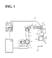
- FIG. 1 is a schematic general view of a spot welding apparatus according to an embodiment, illustrating an exemplary configuration of the spot welding apparatus.
- a spot welding apparatus 1 includes a spot welding robot 2 (hereinafter referred to as "robot 2"), a welding power source 3, a controller 4, and a spot welding gun 10.
- the robot 2 is a multi-articular robot having a plurality of joint axes J1 to J6.
- the robot 2 includes a base 13, a rotary portion 14, a lower arm 15, an upper arm 16, a first wrist 17, a second wrist 18, and a wrist flange 19. These elements are rotatable relative to each other.
- the rotary portion 14 is coupled to the base 13 rotatably about the joint axis J1.
- the lower arm 15 is coupled to the rotary portion 14 rotatably about the joint axis J2, which is approximately orthogonal to the joint axis J1.
- the upper arm 16 is coupled to the lower arm 15 rotatably about the joint axis J3, which is approximately parallel to the joint axis J2.
- the first wrist 17 is coupled to the upper arm 16 rotatably about the joint axis J4, which is approximately orthogonal to the joint axis J3.
- the second wrist 18 is coupled to the first wrist 17 rotatably about the joint axis J5, which is approximately orthogonal to the joint axis J4.
- the wrist flange 19 is coupled to the second wrist 18 rotatably about the joint axis J6, which is approximately orthogonal to the joint axis J5.
- the robot 2 includes robot-dedicated motors M1 to M6, not shown (hereinafter collectively referred to as a robot-dedicated motor M), which respectively correspond to the joint axes J1 to J6 to drive the robot 2.
- the robot-dedicated motor M has its operations controlled by the controller 4. While the robot-dedicated motor M is specifically a servo motor, this should not be construed in a limiting sense. Other examples of the motor include a hydraulic pressure motor.
- the encoder 20 outputs, to the controller 4, an encoder value indicating the rotation degree and rotation angle of the robot-dedicated motor M.
- the robot 2 is illustrated as a 6-axis robot, this configuration should not be construed in a limiting sense. It is also possible to use, for example, a 7-axis robot or an 8-axis robot, other than the 6-axis robot.
- the spot welding gun 10 is mounted to the distal end of the robot 2.
- the spot welding gun 10 has its position, angle, orientation, and other parameters controlled by the controller 4's control of the robot-dedicated motor M.
- the spot welding gun 10 is a C-type spot welding gun, and includes a housing 10a, a gun arm 10b, a fixed electrode 10c, and a movable electrode 10d. While the spot welding gun 10 is illustrated as a C-type spot welding gun, this should not be construed in a limiting sense. It is also possible to use any other type of spot welding gun, examples including a one-side driven X-type spot welding gun.
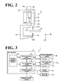
- FIG. 2 is a schematic enlarged view of the spot welding gun shown in FIG. 1 .
- the housing 10a is indicated in phantom lines.
- the housing 10a accommodates a gun-dedicated motor 10e, a ball screw mechanism 10f, an encoder 10g, and a reducer 10h.
- the gun-dedicated motor 10e has its operation controlled by the controller 4, similarly to the robot-dedicated motor M, so as to move the movable electrode 10d. While the gun-dedicated motor 10e is specifically a servo motor, any other kind of motor is possible insofar as the motor can be position-controlled by the controller 4, as described later.
- the ball screw mechanism 10f includes a screw shaft 10f 1 and a nut 10f 2 .
- the screw shaft 10f 1 has one end coupled to the output shaft of the gun-dedicated motor 10e through the reducer 10h, and another end in the vicinity of which the nut 10f 2 is threaded through a ball, not shown.
- the movable electrode 10d is mounted to the nut 10f 2 .
- the ball screw mechanism 10f is a mechanism to convert the rotational motion of the gun-dedicated motor 10e into linear motion of the movable electrode 10d.
- the encoder 10g is mounted to the gun-dedicated motor 10e and outputs, to the controller 4, an encoder value indicating the rotation degree and rotation angle of the gun-dedicated motor 10e.
- the gun arm 10b has an approximately C-shaped side view. Also the gun arm 10b is elasticity deformable within a predetermined range of stress, and is made of light metal such as an aluminum alloy and beryllium copper.
- the elastic deformation of the gun arm 10b is taken into consideration when the welding pressure that the movable electrode 10d applies on a workpiece W is turned into a desired value. This will be described later by referring to FIG. 3 .
- the gun arm 10b has one end 10b 1 coupled to the robot 2 through the housing 10a.
- the gun arm 10b has another end 10b 2 to which the fixed electrode 10c is fixed.
- the movable electrode 10d is disposed at a position opposite the fixed electrode 10c.
- the axis direction of the fixed electrode 10c and the axis direction of the movable electrode 10d are each assumed “Z axis direction”.
- An axis direction orthogonal to the Z axis direction, that is, the lateral direction in FIG. 2 is assumed "X axis direction”.
- the workpiece W is inserted between them as a to-be-welded object.
- the workpiece W is appropriately fixed on a stand or like element, which is not elaborated in the drawings.
- FIG. 3 is a block diagram illustrating a configuration of the spot welding apparatus 1 shown in FIG. 1 .
- the controller 4 includes a robot-dedicated motor control section 4a, a gun-dedicated motor control section 4b, a welding control section 4c, and a bending-degree calculation section 4d.
- the control sections 4a, 4b, and 4c are coupled to each other in a mutually communicable manner.
- the bending-degree calculation section 4d is coupled to the robot-dedicated motor control section 4a and the gun-dedicated motor control section 4b in a communicable manner.
- the robot-dedicated motor control section 4a controls the operation of the robot-dedicated motor M, thereby driving the robot 2.
- the gun-dedicated motor control section 4b controls the operation of the gun-dedicated motor 10e, thereby controlling the movable electrode 10d of the spot welding gun 10 to expand or contract so as to hold the workpiece W under pressure between the fixed electrode 10c and the movable electrode 10d, or so as to release the workpiece W that is being held under pressure.
- FIG. 3 shows only those elements, among the configuration of the controller 4, that are particularly relevant to the description of this embodiment.
- Spot welding includes holding a workpiece under pressure between the fixed electrode and the movable electrode, and with the workpiece in this state, allowing current to flow between the fixed electrode and the movable electrode for a predetermined period of time.
- the welding pressure of the movable electrode against the workpiece is preferably at a desired value.
- a torque command is set in advance through an experiment or the like for the gun-dedicated motor to make the welding pressure at the desired value.
- the torque command is output to the gun-dedicated motor, that is, the gun-dedicated motor is torque-controlled when the workpiece is held under pressure and subjected to spot welding.
- the ball screw mechanism has its static friction coefficient and dynamic friction coefficient varied due to break-in or other factors that develop through repeated operations.
- a possible situation was that as time elapses, the use of the torque command set in advance in the motor control as described above may not ensure the desired value for the welding pressure against the workpiece.
- these friction coefficients vary depending on the atmosphere temperature of the spot welding apparatus. Hence, a possible situation was that the friction coefficients may vary depending on the atmosphere temperature while at the same time the desired value for the welding pressure may not be ensured. Further, a possible situation was that under the influence of gravity, which depends on the posture of the spot welding gun, the desired value for the welding pressure against the workpiece may not be ensured. Furthermore, when the movable electrode is brought into contact with the workpiece at comparatively high speed, a possible situation was that the welding pressure increases over the desired value, failing to improve the tact time.
- the controller 4 performs position control of outputting a position command to the gun-dedicated motor 10e, so as to control the operation of the gun-dedicated motor 10e.
- Position control of the gun-dedicated motor 10e in this manner ensures control of the position of the movable electrode 10d, which is driven by the gun-dedicated motor 10e, without influence such as of changes in the friction coefficients of the ball screw mechanism 10f. As a result, the welding pressure is turned into the desired value.
- FIG. 3 will be further described.
- the gun-dedicated motor control section 4b performs position control to control the operation of the gun-dedicated motor 10e, thereby expanding or contracting the movable electrode 10d.
- the robot-dedicated motor control section 4a performs position control to control the operation of the robot-dedicated motor M, thereby driving the robot 2.
- the welding control section 4c is coupled to the welding power source 3. With the workpiece W in held state under pressure between the fixed electrode 10c and the movable electrode 10d, the welding control section 4c allows the current from the welding power source 3 to flow between the fixed electrode 10c and the movable electrode 10d, thus performing spot welding.
- the bending-degree calculation section 4d calculates the bending degrees of the gun arm 10b at the time when the desired welding pressure is applied to the workpiece W.
- the above-described position control of the gun-dedicated motor 10e and position control of the robot-dedicated motor M are performed based on the bending degrees calculated by the bending-degree calculation section 4d. This will be described in detail below.
- FIG. 4 is a schematic view of the fixed electrode 10c and the movable electrode 10d in a state of holding between them the workpiece W under pressure.
- the gun arm 10b elastically deforms in the Z axis direction and the X axis direction, since the gun arm 10b is elastically deformable as described above.
- FIG. 4 the gun arm 10b that is not yet elastically deformed is indicated in imaginary lines. Also, FIG. 4 shows the gun arm 10b in its elastically deformed state in an exaggerated manner for the sake of description, with the result that the length of each electrode and other dimensions might be illustrated as contradicting themselves before and after the elastic deformation.
- the bending-degree calculation section 4d takes into consideration this elastic deformation phenomenon of the gun arm 10b when the workpiece W is held under pressure, and obtains, using formulae, the bending degrees of the gun arm 10b at the time when the desired welding pressure is applied to the workpiece W.
- the welding pressure that the movable electrode 10d applies to the workpiece W is assumed F.
- the angle defined by the vector of the welding pressure F and the X axis direction is assumed ⁇ .
- the welding pressure F is represented based on Hooke's law as in the following Formulae (1) and (2).
- the spring constants k(z) and k(x) in Formulae (1) and (2) are calculated in advance through an experiment.
- a welding pressure sensor is mounted to the movable electrode 10d or another element that applies pressure to the workpiece W
- a bending sensor is mounted to the gun arm 10b.
- the movable electrode 10d is operated to expand toward the fixed electrode 10c by any predetermined value (hereinafter referred to as "first predetermined value"). This causes the workpiece W to be held under pressure and the gun arm 10b to elastically deform.
- the welding pressure output from the welding pressure sensor is assumed F 1 .
- the bending degree of the gun arm 10b in the Z axis direction output from the bending sensor is assumed z 1 .
- the bending degree of the gun arm 10b in the X axis direction is assumed x 1 .
- Formulae (1) and (2) respectively turn into Formulae (3) and (4).
- F 1 ⁇ sin ⁇ 1 k z ⁇ z 1
- F 1 ⁇ cos ⁇ 1 k x ⁇ x 1
- ⁇ 1 denotes the angle defined by the vector of the welding pressure F 1 and the X axis direction.
- the movable electrode 10d is operated to expand toward the fixed electrode 10c by a second predetermined value different from the first predetermined value. This causes the workpiece W to be held under pressure and the gun arm 10b to elastically deform.
- the outputs of the welding pressure sensor and the bending sensor in this state are read, similarly to the above.
- the welding pressure output from the welding pressure sensor is assumed F 2 .
- the bending degree of the gun arm 10b in the Z axis direction output from the bending sensor is assumed z 2 .
- the bending degree of the gun arm 10b in the X axis direction is assumed x 2 .
- Formulae (1) and (2) respectively turn into the following Formulae (5) and (6).
- F 2 ⁇ sin ⁇ 2 k z ⁇ z 2
- F 2 ⁇ cos ⁇ 2 k x ⁇ x 2
- ⁇ 2 denotes the angle defined by the vector of the welding pressure F 2 and the X axis direction.
- Formulae (3) to (6) are solved to obtain the spring constants k(z) and k(x). Specifically, for example, Formulae (3) and (4) are solved to cancel ⁇ 1 , while Formulae (5) and (6) are solved to cancel ⁇ 2 .
- These formulae are solved to obtain the spring constants k(z) and k(x).
- Poisson's ratio ⁇ of the gun arm 10b is also calculated.
- Poisson's ratio ⁇ is the ratio of lateral strain [%] to longitudinal strain [%].
- Poisson's ratio ⁇ can be obtained by the following Formula (7) or Formula (8).
- Poisson ⁇ s ratio v x 1 / x length / z 1 / z length
- Poisson ⁇ s ratio v x 2 / x length / z 2 / z length
- Poisson's ratio ⁇ is constant insofar as the material of the gun arm 10b is the same, and therefore, can be calculated using either Formula (7) or (8).
- the spring constants k(z) and k(x) and Poisson's ratio ⁇ are calculated, for example, before shipment of the spot welding apparatus 1 from a plant. This, however, should not be construed in a limiting sense. The calculation may also be performed after shipment of the spot welding apparatus 1 and at the site where the spot welding is actually performed.
- the spring constants k(z) and k(x) and Poisson's ratio ⁇ thus obtained of the gun arm 10b are characteristic of the gun arm 10b, and therefore, their values basically remain constant regardless of the greatness of the welding pressure F. Hence, once the spring constants k(z) and k(x) and Poisson's ratio ⁇ are obtained, the bending degrees z and x at the time when any welding pressure is applied can be calculated using formulae before the welding pressure is actually applied.
- formulae containing the spring constants k(z) and k(x) are used to calculate bending degrees z and x at the time when the desired value, at which appropriate spot welding is performed, is achieved for the welding pressure F, which is applied on the workpiece W by the movable electrode 10d of the gun arm 10b. Based on the calculated bending degrees z and x, the movable electrode 10d and the robot 2 are controlled.
- the bending degrees z and x each correspond to the amount of error between the position at which the movable electrode 10d contacts the workpiece W and the target position of the movable electrode 10d at which the welding pressure F is at its desired value.
- controlling the operations of the movable electrode 10d and the robot 2 based on the bending degrees z and x matches the target position with the contact position of the movable electrode 10d with the workpiece W.
- a desired welding pressure Fa is input into the bending-degree calculation section 4d of the controller 4 through an input device, not shown.
- the bending-degree calculation section 4d calculates the gun arm 10b's bending degree z in the Z axis direction and bending degree x in the X axis direction.
- the bending degree z can be obtained using Formula (9), which is a modified form of Formula (1)
- the bending degree x can be obtained using Formula (10), which is a modified form of Formula (2).
- Formulae (9) and (10) are solved to cancel ⁇ .
- a relation formula of the bending degree z and the bending degree x is derived from Poisson's ratio v.
- formulae are used to calculate the gun arm 10b's bending degree z in the Z axis direction and bending degree x in the X axis direction at the time when the welding pressure Fa is applied on the workpiece W. This ensures accurate calculation of the bending degrees z and x.
- the bending-degree calculation section 4d outputs to the gun-dedicated motor control section 4b the bending degree z calculated at Formula (9) and the bending degree x calculated at Formula (10), and also outputs the bending degree z and the bending degree x to the robot-dedicated motor control section 4a.
- the gun-dedicated motor control section 4b controls the operation of the gun-dedicated motor 10e based on the bending degree z, the bending degree x, and the encoder value of the encoder 10g. Specifically, the gun-dedicated motor control section 4b controls the operation of the gun-dedicated motor 10e to move the movable electrode 10d by a degree corresponding a correction amount a, which is calculated based on the bending degree z and the bending degree x.
- the distal end of the movable electrode 10d is at a position displaced in a direction away from the target position. More specifically, referring to FIG. 4 , the displacements are toward the negative side in the Z axis direction and the positive side in the X axis direction. In view of this, in this case, the movable electrode 10d is moved (expanded) by a degree to correct the displacements.
- the gun-dedicated motor control section 4b controls the operation of the gun-dedicated motor 10e to move in the positive direction in which the movable electrode 10d corrects its displacements in the Z axis direction and in the X axis direction; in other words, to move toward the fixed electrode 10c by a degree corresponding to the correction amount a, which is obtained from the bending degree z and the bending degree x.
- the robot-dedicated motor control section 4a controls the operation of the robot-dedicated motor M based on the bending degree z and the bending degree x and on the encoder value of the encoder 20. Specifically, the robot-dedicated motor control section 4a controls the operation of the robot-dedicated motor M to drive the robot 2 by a degree corresponding to the bending degree z and the bending degree x.
- the robot-dedicated motor control section 4a controls the operation of the robot-dedicated motor M to drive the robot 2 by a degree corresponding to the bending degree x in the negative direction, in which the displacement in the X axis direction is corrected.
- the robot-dedicated motor control section 4a controls the operation of the robot-dedicated motor M to drive the robot 2 by a degree corresponding to the bending degree z in the negative direction, in which the displacement in the Z axis direction is corrected.
- position control is performed with respect to the operation of the gun-dedicated motor 10e and the operation of the robot-dedicated motor M, thereby matching the contact positions of the fixed electrode 10c and the movable electrode 10d with the respective target positions.
- This ensures that the welding pressure F, which the movable electrode 10d applies on the workpiece W, is at the desired value.
- the welding pressure F being at its desired value, appropriate spot welding is performed.
- matching the contact positions of the fixed electrode 10c and the movable electrode 10d with the respective target positions eliminates or minimizes unnecessary stress to act on the workpiece W. This ensures appropriate spot welding without strain deformation.
- a common configuration is to: obtain through an experiment a table of relationship between, for example, the torque command to the gun-dedicated motor and the bending degree; and at the time of the spot welding, to search the table for a bending degree corresponding to the torque command of interest and to perform robot control based on the obtained bending degree.
- FIG. 5 is a flowchart of an operation of the controller 4 of the spot welding apparatus 1, including an initial setting.
- the bending-degree calculation section 4d of the controller 4 obtains in advance the spring constants k(z) and k(x) of the gun arm 10b by an experiment (step S1). Specifically, the bending-degree calculation section 4d solves four Formulae (3) to (6) obtained by an experiment, thereby calculating the spring constants k(z) and k(x), and stores the spring constants in a memory, not shown. Further, at step S1, Poisson's ratio ⁇ of the gun arm 10b is also calculated and stored in a memory. Step S1 is an initial setting of the spot welding apparatus 1.
- the bending-degree calculation section 4d uses Formulae (9) and (10) to calculate the bending degrees z and x of the gun arm 10b at the time when the desired welding pressure Fa is applied on the workpiece W (step S2).
- the bending-degree calculation section 4d outputs the bending degree z and the bending degree x to the gun-dedicated motor control section 4b, while at the same time outputs the bending degree z and the bending degree x to the robot-dedicated motor control section 4a.
- the gun-dedicated motor control section 4b of the controller 4 position-controls the gun-dedicated motor 10e based on the bending degrees z and x. Specifically, the gun-dedicated motor control section 4b controls the operation of the gun-dedicated motor 10e to move the movable electrode 10d by a degree corresponding to the correction amount a, which is calculated based on the bending degrees z and x (step S3).
- the robot-dedicated motor control section 4a of the controller 4 position-controls the robot-dedicated motor M based on the bending degrees z and x. Specifically, the robot-dedicated motor control section 4a controls the operation of the robot-dedicated motor M to drive the robot 2 by a degree corresponding to the bending degrees z and x (step S4).
- the processings at step S3 and step S4 correct the contact position of the movable electrode 10d with the workpiece W to match the target position of the movable electrode 10d at which the welding pressure F is at its desired value, and ensure the desired value for the welding pressure that the movable electrode 10d applies on the workpiece W.
- step S3 and step S4 are executed synchronously with one another. This ensures early and accurate attainment of the target position for the contact position of the movable electrode 10d with the workpiece W.
- the gun-dedicated motor is torque-controlled while the robot-dedicated motor is position-controlled
- the operation of one of the motors lags behind the other due to a difference in control loop.
- the gun-dedicated motor 10e and the robot-dedicated motor M both have their operations controlled by position control. This ensures that the gun-dedicated motor 10e and the robot-dedicated motor M are controlled with their position control loops synchronized with one another. This keeps the operation of one of the motors from lagging behind the other, and ensures early and accurate attainment of the target position for the contact position of the movable electrode 10d with the workpiece W.
- the welding control section 4c of the controller 4 supplies current to between the fixed electrode 10c and the movable electrode 10d for a predetermined period of time, thus performing spot welding (step S5).
- the controller 4 moves the movable electrode 10d in a direction away from the fixed electrode 10c, thereby releasing the workpiece W, and turns the robot 2 into operation to move the spot welding gun 10 to a next welding point.
- the controller 4 of the spot welding apparatus 1 performs position control of outputting a position command to the gun-dedicated motor 10e, so as to control the operation of the gun-dedicated motor 10e. This ensures that the welding pressure that the movable electrode 10d of the spot welding gun 10 applies on the workpiece W is at the desired value.
- the controller 4 acquires the amount of wear every time a predetermined plurality of spot weldings are performed. Then, when the workpiece W is held under pressure, the controller 4 corrects the position of the fixed electrode 10c and the amount of expansion or contraction of the movable electrode 10d by a degree corresponding to the acquired amount of wear of each of the electrodes 10c and 10d.
- the spot welding apparatus 1 performs the above-described correction associated with the wear of the electrodes, and then further performs the correction associated with the elastic deformation of the gun arm 10b.
- the spot welding gun 10 is mounted to the distal end of the robot 2, this should not be construed in a limiting sense.
- the spot welding gun may be a fixed-type spot welding gun.
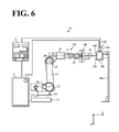
- FIG. 6 A specific example is shown in FIG. 6 .
- a spot welding gun 110 is fixed to a column 110i instead of the distal end of a robot 102.
- the configuration of the spot welding gun 110 is approximately the same as the configuration of the spot welding gun 10.
- a hand 130 is mounted that is capable of gripping the workpiece W.
- the spot welding gun 110 is disposed within the operable range of the hand 130 of the robot 102.
- the controller 4 turns the hand 130 into operation to grip the workpiece W and insert the workpiece W between the fixed electrode 10c and the movable electrode 10d of the spot welding gun 110. Then, similarly to the above description, the controller 4 controls the operations of the gun-dedicated motor 10e and the robot-dedicated motor M based on the bending degrees z and x and other parameters to correct the positions of the movable electrode 10d and the robot 102, and executes the spot welding.
Landscapes
- Engineering & Computer Science (AREA)
- Mechanical Engineering (AREA)
- Robotics (AREA)
- Resistance Welding (AREA)
Applications Claiming Priority (1)
| Application Number | Priority Date | Filing Date | Title |
|---|---|---|---|
| JP2012186925A JP2014042931A (ja) | 2012-08-27 | 2012-08-27 | スポット溶接装置 |
Publications (1)
| Publication Number | Publication Date |
|---|---|
| EP2705923A1 true EP2705923A1 (fr) | 2014-03-12 |
Family
ID=48790198
Family Applications (1)
| Application Number | Title | Priority Date | Filing Date |
|---|---|---|---|
| EP13175140.6A Withdrawn EP2705923A1 (fr) | 2012-08-27 | 2013-07-04 | Appareil de soudage par points avec un contrôleur apte à calculer le degré de flexion de bras supportant une électrode et à corriger cette flexion |
Country Status (4)
| Country | Link |
|---|---|
| US (1) | US20140054272A1 (fr) |
| EP (1) | EP2705923A1 (fr) |
| JP (1) | JP2014042931A (fr) |
| CN (1) | CN103624385A (fr) |
Cited By (1)
| Publication number | Priority date | Publication date | Assignee | Title |
|---|---|---|---|---|
| DE102015006217B4 (de) * | 2014-05-21 | 2021-03-25 | Fanuc Corporation | Punktschweißanlage und Punktschweißverfahren |
Families Citing this family (10)
| Publication number | Priority date | Publication date | Assignee | Title |
|---|---|---|---|---|
| JP6062908B2 (ja) * | 2014-11-06 | 2017-01-18 | ファナック株式会社 | 被加圧物へ作用する加圧力を一定とすることができるスポット溶接システム、方法、およびコンピュータプログラム |
| CN105489698A (zh) * | 2015-11-23 | 2016-04-13 | 浙江昱辉阳光能源江苏有限公司 | 一种可提升焊带利用率的太阳能组件 |
| CN105527989A (zh) * | 2015-12-18 | 2016-04-27 | 重庆长安工业(集团)有限责任公司 | 基于位置控制模式的工业机器人伺服焊钳力矩控制方法 |
| US10639739B2 (en) * | 2016-07-29 | 2020-05-05 | Fanuc America Corporation | Sensorless pressure change detection for servo gun |
| JP7216479B2 (ja) * | 2018-03-28 | 2023-02-01 | ダイハツ工業株式会社 | スポット溶接装置 |
| SE542275C2 (en) * | 2018-07-04 | 2020-03-31 | Car O Liner Group Ab | A method for controlling a spot welding arrangement and a spot welding arrangement |
| DE102020200617A1 (de) * | 2020-01-21 | 2021-07-22 | Robert Bosch Gesellschaft mit beschränkter Haftung | Vorrichtung für eine schweisssteuerung und verfahren zur erzeugung von kraftwerten bei der steuerung eines schweisswerkzeugs |
| CN113600988B (zh) * | 2021-08-12 | 2023-01-31 | 合肥三宇电器有限责任公司 | 一种基于伺服电机驱动的电阻点焊机加压控制方法 |
| DE102022213307A1 (de) * | 2022-12-08 | 2024-06-13 | Robert Bosch Gesellschaft mit beschränkter Haftung | Vorrichtung und verfahren zur positionsregelung eines zangenförmigen werkzeugs |
| DE102024207052A1 (de) * | 2024-07-26 | 2026-01-29 | Robert Bosch Gesellschaft mit beschränkter Haftung | Vorrichtung für eine Schweißanlage, Schweißanlage und Verfahren zum Behandeln von Störgrößen beim Schweißen |
Citations (4)
| Publication number | Priority date | Publication date | Assignee | Title |
|---|---|---|---|---|
| JPH06312273A (ja) * | 1993-04-30 | 1994-11-08 | Nachi Fujikoshi Corp | 溶接ガン加圧力制御方法 |
| JP2596722B2 (ja) | 1995-02-06 | 1997-04-02 | 川崎重工業株式会社 | スポット溶接方法および装置 |
| US6274840B1 (en) * | 1998-02-04 | 2001-08-14 | Nissan Motor Co., Ltd. | Electrode position detecting system and method for spot welders |
| JP2002321066A (ja) * | 2001-04-23 | 2002-11-05 | Dengensha Mfg Co Ltd | 抵抗溶接機用制御装置 |
Family Cites Families (4)
| Publication number | Priority date | Publication date | Assignee | Title |
|---|---|---|---|---|
| JP3503359B2 (ja) * | 1996-09-25 | 2004-03-02 | トヨタ自動車株式会社 | 溶接ガンの加圧力制御方法および装置 |
| JP4711041B2 (ja) * | 2003-08-26 | 2011-06-29 | 株式会社不二越 | スポット溶接方法 |
| JP4899175B2 (ja) * | 2005-04-28 | 2012-03-21 | 株式会社不二越 | スポット溶接方法とスポット溶接システム |
| JP2009056480A (ja) * | 2007-08-31 | 2009-03-19 | Fanuc Ltd | スポット溶接ガンを用いたスポット溶接方法 |
-
2012
- 2012-08-27 JP JP2012186925A patent/JP2014042931A/ja active Pending
-
2013
- 2013-07-04 EP EP13175140.6A patent/EP2705923A1/fr not_active Withdrawn
- 2013-07-22 US US13/947,103 patent/US20140054272A1/en not_active Abandoned
- 2013-08-23 CN CN201310373584.2A patent/CN103624385A/zh active Pending
Patent Citations (4)
| Publication number | Priority date | Publication date | Assignee | Title |
|---|---|---|---|---|
| JPH06312273A (ja) * | 1993-04-30 | 1994-11-08 | Nachi Fujikoshi Corp | 溶接ガン加圧力制御方法 |
| JP2596722B2 (ja) | 1995-02-06 | 1997-04-02 | 川崎重工業株式会社 | スポット溶接方法および装置 |
| US6274840B1 (en) * | 1998-02-04 | 2001-08-14 | Nissan Motor Co., Ltd. | Electrode position detecting system and method for spot welders |
| JP2002321066A (ja) * | 2001-04-23 | 2002-11-05 | Dengensha Mfg Co Ltd | 抵抗溶接機用制御装置 |
Cited By (1)
| Publication number | Priority date | Publication date | Assignee | Title |
|---|---|---|---|---|
| DE102015006217B4 (de) * | 2014-05-21 | 2021-03-25 | Fanuc Corporation | Punktschweißanlage und Punktschweißverfahren |
Also Published As
| Publication number | Publication date |
|---|---|
| US20140054272A1 (en) | 2014-02-27 |
| JP2014042931A (ja) | 2014-03-13 |
| CN103624385A (zh) | 2014-03-12 |
Similar Documents
| Publication | Publication Date | Title |
|---|---|---|
| EP2705923A1 (fr) | Appareil de soudage par points avec un contrôleur apte à calculer le degré de flexion de bras supportant une électrode et à corriger cette flexion | |
| JP7263412B2 (ja) | 駆動装置、ロボット装置、物品の製造方法、制御方法、制御プログラム、記録媒体 | |
| JP7227073B2 (ja) | ワーク回転装置およびロボットシステム | |
| US7260450B2 (en) | Apparatus and method for controlling elastic actuator | |
| US20190099887A1 (en) | System and method for calibrating tool center point of robot | |
| EP3078459B1 (fr) | Procédé de commande de robot, appareil robotique, programme et support d'enregistrement | |
| JP6153316B2 (ja) | ロボットシステム及びロボットシステムの制御方法 | |
| JP7015267B2 (ja) | ロボット制御装置及びロボットシステム | |
| CN105965505A (zh) | 机器人控制方法、机器人装置、程序和记录介质 | |
| JP5786550B2 (ja) | 6軸ロボットの軸間オフセット検出方法 | |
| JP5426443B2 (ja) | 摩擦撹拌溶接方法および摩擦撹拌溶接装置 | |
| JP2016168650A (ja) | ロボット装置、ロボット制御方法、プログラム及び記録媒体 | |
| WO2016110320A1 (fr) | Procédé pour l'estimation de forces externes et de couples sur un bras de robot | |
| JP6542629B2 (ja) | 加工ツールの位置決め装置及び位置決め方法 | |
| JP5672173B2 (ja) | 6軸ロボットの軸間オフセット検出方法 | |
| JP2019195880A (ja) | 関節型ロボット及びそのガススプリングのガス減少状態の推定方法 | |
| JP6576824B2 (ja) | ロボット制御装置 | |
| JP2016215316A (ja) | ロボット装置、ロボット制御方法、プログラム、記録媒体及び組立部品の製造方法 | |
| JP7201537B2 (ja) | スポット溶接システム | |
| JP7154748B2 (ja) | ロボットシステム、物品の製造方法、制御方法、制御プログラム、及び記録媒体 | |
| JP7227012B2 (ja) | 多関節ロボットの制御装置 | |
| JP6091272B2 (ja) | 多関節ロボットのバネ定数補正装置 | |
| JP2013071224A (ja) | 把持機構 | |
| JP7481579B2 (ja) | ロボット装置またはワークに作用する外力の許容値を算出する計算装置およびロボットの制御装置 | |
| JPS63251811A (ja) | 産業用ロボツトの制御装置 |
Legal Events
| Date | Code | Title | Description |
|---|---|---|---|
| PUAI | Public reference made under article 153(3) epc to a published international application that has entered the european phase |
Free format text: ORIGINAL CODE: 0009012 |
|
| AK | Designated contracting states |
Kind code of ref document: A1 Designated state(s): AL AT BE BG CH CY CZ DE DK EE ES FI FR GB GR HR HU IE IS IT LI LT LU LV MC MK MT NL NO PL PT RO RS SE SI SK SM TR |
|
| AX | Request for extension of the european patent |
Extension state: BA ME |
|
| 17P | Request for examination filed |
Effective date: 20140509 |
|
| RBV | Designated contracting states (corrected) |
Designated state(s): AL AT BE BG CH CY CZ DE DK EE ES FI FR GB GR HR HU IE IS IT LI LT LU LV MC MK MT NL NO PL PT RO RS SE SI SK SM TR |
|
| GRAP | Despatch of communication of intention to grant a patent |
Free format text: ORIGINAL CODE: EPIDOSNIGR1 |
|
| RIC1 | Information provided on ipc code assigned before grant |
Ipc: B23K 11/11 20060101AFI20141205BHEP Ipc: B23K 11/25 20060101ALI20141205BHEP Ipc: B23K 11/31 20060101ALI20141205BHEP Ipc: B23K 11/36 20060101ALI20141205BHEP |
|
| INTG | Intention to grant announced |
Effective date: 20150112 |
|
| STAA | Information on the status of an ep patent application or granted ep patent |
Free format text: STATUS: THE APPLICATION IS DEEMED TO BE WITHDRAWN |
|
| 18D | Application deemed to be withdrawn |
Effective date: 20150523 |