EP2705926B1 - Finishing process for making blade slots in a rotor disc - Google Patents
Finishing process for making blade slots in a rotor disc Download PDFInfo
- Publication number
- EP2705926B1 EP2705926B1 EP13183815.3A EP13183815A EP2705926B1 EP 2705926 B1 EP2705926 B1 EP 2705926B1 EP 13183815 A EP13183815 A EP 13183815A EP 2705926 B1 EP2705926 B1 EP 2705926B1
- Authority
- EP
- European Patent Office
- Prior art keywords
- grinder
- pass
- process according
- finishing
- symmetry plane
- Prior art date
- Legal status (The legal status is an assumption and is not a legal conclusion. Google has not performed a legal analysis and makes no representation as to the accuracy of the status listed.)
- Active
Links
Images

Classifications
-
- B—PERFORMING OPERATIONS; TRANSPORTING
- B24—GRINDING; POLISHING
- B24B—MACHINES, DEVICES, OR PROCESSES FOR GRINDING OR POLISHING; DRESSING OR CONDITIONING OF ABRADING SURFACES; FEEDING OF GRINDING, POLISHING, OR LAPPING AGENTS
- B24B19/00—Single-purpose machines or devices for particular grinding operations not covered by any other main group
- B24B19/02—Single-purpose machines or devices for particular grinding operations not covered by any other main group for grinding grooves, e.g. on shafts, in casings, in tubes, homokinetic joint elements
-
- B—PERFORMING OPERATIONS; TRANSPORTING
- B23—MACHINE TOOLS; METAL-WORKING NOT OTHERWISE PROVIDED FOR
- B23C—MILLING
- B23C2220/00—Details of milling processes
- B23C2220/36—Production of grooves
- B23C2220/366—Turbine blade grooves
-
- B—PERFORMING OPERATIONS; TRANSPORTING
- B23—MACHINE TOOLS; METAL-WORKING NOT OTHERWISE PROVIDED FOR
- B23P—METAL-WORKING NOT OTHERWISE PROVIDED FOR; COMBINED OPERATIONS; UNIVERSAL MACHINE TOOLS
- B23P15/00—Making specific metal objects by operations not covered by a single other subclass or a group in this subclass
- B23P15/006—Making specific metal objects by operations not covered by a single other subclass or a group in this subclass turbine wheels
-
- F—MECHANICAL ENGINEERING; LIGHTING; HEATING; WEAPONS; BLASTING
- F01—MACHINES OR ENGINES IN GENERAL; ENGINE PLANTS IN GENERAL; STEAM ENGINES
- F01D—NON-POSITIVE DISPLACEMENT MACHINES OR ENGINES, e.g. STEAM TURBINES
- F01D5/00—Blades; Blade-carrying members; Heating, heat-insulating, cooling or antivibration means on the blades or the members
- F01D5/30—Fixing blades to rotors; Blade roots ; Blade spacers
- F01D5/3007—Fixing blades to rotors; Blade roots ; Blade spacers of axial insertion type
Definitions
- the present invention concerns a finishing process for making blade slots in a rotor disc.
- the rotating discs provided in gas turbines for example for aeronautical propulsion, for marine propulsion or for the production of electricity, have a plurality of slots made along their periphery for mounting respective blades.
- the blades comprise respective roots which have a profile complementary to that of the slots so that they can be inserted and secured in the slots.
- each slot is defined by a bottom surface, called 'bottom', and two lateral surfaces, called 'sides', which are shaped so as to form the above-mentioned lobes and are joined by means of the bottom.
- broaching process i.e. a chip removal process performed using a series of cutting tools with defined shapes, such as to rough and finish the surfaces of the slots.
- the broaching process has a number of drawbacks:
- the process described is not optimal in terms of the duration of the finishing grinders, the finishing times and the flexibility of the tools.
- the contacts of the finishing grinders on the sides throughout the length of the pass tend to develop a relatively large quantity of heat, which can cause local overheating and therefore compromise the surface integrity of the turbine disc.
- the requirements of surface integrity for the turbine discs are very strict as regards the entity of the residual tensions and the sub-surface extent of the portion of material which is altered due to the mechanical actions (shear strain) and thermal actions (high temperatures in the chip formation area) exercised by the finishing tools.
- EP1967307 concerns the production of slots, defined by at least two roughing operations, performed by means of respective cutters, and by a finishing operation performed by means of a grinder.
- this solution entails a cycloidal movement of the cutters, which allows rapid ejection of the chips produced by the machining.
- the grinder has a profile complementary to that of the slot to be formed and is fed forward with a rectilinear motion.
- the object of the present invention is to provide a finishing process for making blade slots in a rotor disc, which simply and inexpensively solves the problems described above.
- the number 1 indicates, as a whole, a rotor disc (partially illustrated) for a compressor or for a turbine, for example for aeronautical or marine propulsion or for the production of electricity.
- the rotor disc 1 has a rotation axis 2 and is radially delimited by a lateral surface 4, on which a plurality of slots 5 is provided.
- the slots 5 are angularly spaced about the rotation axis 2 and substantially have a multiple lobe or "tree" profile.
- each slot 5 is defined by a bottom surface 9, called “bottom”, and by two lateral surfaces 10, called “sides”, facing each other and connected to the bottom 9.
- each slot 5 are symmetrical with respect to a symmetry plane 11, converge towards the bottom 9 and are shaped so as to present a plurality of lobes or projections.
- the symmetry plane 11 of each slot 5 is radial with respect to the rotation axis 2.
- the symmetry plane 11 of each slot 5 is inclined with respect to the rotation axis 2.
- the slots 5 are engaged by respective roots of blades, having an outer form complementary to the profile of the sides 10.
- the blades are mounted by inserting the respective roots in the slots 5 along the respective symmetry planes 11 and are therefore retained radially in the slots 5 due to the particular lobed form of the sides 10.
- Each of the slots 5 is produced by means of one or more roughing operations (not described in detail), performed for example by a broach, grinders or cutters, and by means of a subsequent finishing process.
- the roughing allows slots 5a to be obtained defined by two sides 10a and a bottom 9a, which have a stock to be removed by means of the finishing process.
- the latter is performed using only two grinders, in particular super-abrasive grinders, indicated by the reference numbers 12 ( fig. 2 ) and 13 ( fig. 3 ).
- the abrasive material of the grinders 12,13 is defined by cubic boron nitride (CBN), deposited on an appropriately shaped support.
- CBN cubic boron nitride
- the peripheral speed or cutting speed of the grinders 12,13 is between 20 and 80 m/s; considering the actual dimensions of the grinders 12,13, said peripheral speed translates into the use of electrospindles capable of working at speeds between 40,000 and 100,000 rpm.
- integral oil as cooling lubricant, to avoid excessive development of heat and to keep the abrasive clean of grinding residues.
- the grinder 12 must machine the bottom 9a, hence it has a lateral surface 14 with a profile complementary to that of the bottom 9 to be obtained.
- the grinder 12 is a disc grinder having a rotation axis 15 perpendicular to the symmetry plane 11.
- the grinder 12 is used before the grinder 13, therefore it must have a height, parallel to the rotation axis 15, less than the minimum distance between the sides 10a.
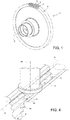
- the grinder 13 must machine the sides 10a and is defined by a finger grinder having a rotation axis 16 which, preferably, is parallel to a radial axis 17 lying on the symmetry plane 11.
- the grinder 13 has a lateral surface 18 defined by a circular directrix and by a generatrix having a profile complementary to that of the sides 10 to be obtained.
- the grinder 13 terminates in a rounded tip 19, which preferably has an axial recess (not illustrated) in order not to come into contact with the bottom 9 previously obtained by means of the grinder 12 and, therefore, avoid peripheral grinding speeds that are too low, which would cause burning and excessive wear of the abrasive material of the grinder 13.
- said stock on each side 10a is less than 0.5 mm, said stock is removed from both the sides 10a by one single pass of the grinder 13, which is moved along a trochoidal or cycloidal path P ( fig. 4 ) comprising the combination of:
- the lateral surface 18 has a diameter smaller than the nominal distance required between the sides 10 of the slot 5, and also with respect to the distance between the sides 10a, so as to perform the grinding in contact with only one of the two sides 10a at a time.
- the amplitude of the loop trajectory B is established so as to alternatively contact both the sides 10a.
- the abrasive material of the grinder 13 comes into contact with each of the two sides 10a in a discontinuous manner, alternating the contact with one and then the other side 10a. Due to this discontinuity of the grinding contact, the machining temperatures are lower and therefore the tools last longer than in the known solutions.
- the loop trajectory B can be defined by a circle or, preferably, by an ellipse.
- the ellipse is defined by a first axis lying on the feed direction A and a second axis orthogonal to the symmetry plane 11. The length of this second axis is finely set (also with micrometric corrections) to obtain the nominal distance required between the sides 10.
- the length of the second axis also during the pass, so as to produce slots of variable width.
- the trochoidal path P permits, in general, reduction of the finishing times, as stock is removed from both the sides 10a during the same pass, and allows the same positioning of the grinder 12 to be maintained on the machine tool for all the finishing passes of the sides 10. Furthermore, the trochoidal path P allows reduction of the temperatures in the machining area, since the contact between the finishing grinder and the sides 10a is of the intermittent type and very brief.
- the finishing grinding is performed with a rectilinear feed path, which maintains the finishing grinder constantly in contact with the part being machined for the entire length of the pass.
- the finish of the bottom 9 frees the bottom 9 itself from the stock, whatever the extent of said stock, hence the axial end of the rounded tip 19 substantially encounters no obstacles to feeding in the direction A during subsequent grinding of the sides 10a.
Landscapes
- Engineering & Computer Science (AREA)
- Mechanical Engineering (AREA)
- Finish Polishing, Edge Sharpening, And Grinding By Specific Grinding Devices (AREA)
- Turbine Rotor Nozzle Sealing (AREA)
- Grinding And Polishing Of Tertiary Curved Surfaces And Surfaces With Complex Shapes (AREA)
- Polishing Bodies And Polishing Tools (AREA)
Applications Claiming Priority (1)
| Application Number | Priority Date | Filing Date | Title |
|---|---|---|---|
| IT000780A ITTO20120780A1 (it) | 2012-09-10 | 2012-09-10 | Procedimento di finitura per realizzare cave per palette in un disco rotore |
Publications (2)
| Publication Number | Publication Date |
|---|---|
| EP2705926A1 EP2705926A1 (en) | 2014-03-12 |
| EP2705926B1 true EP2705926B1 (en) | 2019-01-23 |
Family
ID=47226328
Family Applications (1)
| Application Number | Title | Priority Date | Filing Date |
|---|---|---|---|
| EP13183815.3A Active EP2705926B1 (en) | 2012-09-10 | 2013-09-10 | Finishing process for making blade slots in a rotor disc |
Country Status (3)
| Country | Link |
|---|---|
| EP (1) | EP2705926B1 (it) |
| ES (1) | ES2709600T3 (it) |
| IT (1) | ITTO20120780A1 (it) |
Families Citing this family (3)
| Publication number | Priority date | Publication date | Assignee | Title |
|---|---|---|---|---|
| CN117001380A (zh) * | 2023-09-15 | 2023-11-07 | 德州德隆(集团)机床有限责任公司 | 一种盘类零件的定位工装及其使用方法 |
| CN117583655B (zh) * | 2024-01-18 | 2024-03-29 | 常州市福尔特工具有限公司 | 一种用于大平面加工的高效铣削盘铣刀 |
| CN119407211B (zh) * | 2024-11-12 | 2026-04-21 | 上海电气电站设备有限公司 | 一种轮盘异型叶根槽的车削工艺与检测方法 |
Family Cites Families (4)
| Publication number | Priority date | Publication date | Assignee | Title |
|---|---|---|---|---|
| DE10219012B4 (de) * | 2002-04-27 | 2004-11-04 | Mtu Aero Engines Gmbh | Fräsverfahren |
| US6883234B2 (en) * | 2002-10-07 | 2005-04-26 | United Technologies Corporation | Process for machining axial blade slots in turbine disks for jet engines |
| ATE468936T1 (de) * | 2007-03-08 | 2010-06-15 | Mattias Rutschinski | Verfahren zur herstellung eines mit nuten versehenen rotornabenelementes |
| US8567059B2 (en) * | 2009-07-10 | 2013-10-29 | Pratt & Whitney Canada Corp. | Process for forming a firtree slot in a disc of a rotor of a gas turbine engine |
-
2012
- 2012-09-10 IT IT000780A patent/ITTO20120780A1/it unknown
-
2013
- 2013-09-10 ES ES13183815T patent/ES2709600T3/es active Active
- 2013-09-10 EP EP13183815.3A patent/EP2705926B1/en active Active
Non-Patent Citations (1)
| Title |
|---|
| None * |
Also Published As
| Publication number | Publication date |
|---|---|
| ITTO20120780A1 (it) | 2014-03-11 |
| ES2709600T3 (es) | 2019-04-16 |
| EP2705926A1 (en) | 2014-03-12 |
Similar Documents
| Publication | Publication Date | Title |
|---|---|---|
| EP1930121B1 (en) | Method of machining turbine airfoils by disc tools | |
| CN107107224B (zh) | 具有多转切削齿的轴向滚刀 | |
| US8701287B2 (en) | Method for aerodynamically shaping the leading edge of blisk blades | |
| US8905690B2 (en) | SCEM for heat-resistant materials (star mill) | |
| CN100515631C (zh) | 用于制造涡轮的叉形根部的方法、铣削工具及工具组 | |
| EP2602039A1 (en) | A method of forming a slot in an article | |
| US20100135740A1 (en) | Cutter apparatus and method | |
| EP2705926B1 (en) | Finishing process for making blade slots in a rotor disc | |
| EP2564962B1 (en) | Airfoil machining method | |
| US20160288274A1 (en) | Method of machining surfaces of rotor disc and grinding machine therefor | |
| BR102021018465A2 (pt) | Ferramenta de fresa e método para produção de tais ferramentas de fresa | |
| EP1683597B1 (en) | Method of processing a semi-finished product for the production of a rotor with integral blades | |
| US8014893B2 (en) | Method of machining workpiece with offset tool | |
| KR20100016320A (ko) | 절삭분 유출성이 향상된 공구 | |
| JP6879668B2 (ja) | 切削方法 | |
| CN102917824B (zh) | 在涡轮发动机的涡轮盘上加工槽的方法 | |
| US8689441B2 (en) | Method for machining a slot in a turbine engine rotor disk | |
| US20150258618A1 (en) | Ring-shaped tool for processing a work piece | |
| JP6248748B2 (ja) | ラフィングエンドミル | |
| JP7169223B2 (ja) | 総形削り加工方法 | |
| US20200324350A1 (en) | Milling cutter | |
| JP2010149218A (ja) | 総形フライス | |
| CN103402680A (zh) | 铣削/表面加工方法和装置 | |
| CN108247118B (zh) | 用于加工柴油机机座大小斜面的方法及刀具 | |
| JP2024175294A (ja) | スカイビングカッタ |
Legal Events
| Date | Code | Title | Description |
|---|---|---|---|
| PUAI | Public reference made under article 153(3) epc to a published international application that has entered the european phase |
Free format text: ORIGINAL CODE: 0009012 |
|
| AK | Designated contracting states |
Kind code of ref document: A1 Designated state(s): AL AT BE BG CH CY CZ DE DK EE ES FI FR GB GR HR HU IE IS IT LI LT LU LV MC MK MT NL NO PL PT RO RS SE SI SK SM TR |
|
| AX | Request for extension of the european patent |
Extension state: BA ME |
|
| 17P | Request for examination filed |
Effective date: 20140911 |
|
| RBV | Designated contracting states (corrected) |
Designated state(s): AL AT BE BG CH CY CZ DE DK EE ES FI FR GB GR HR HU IE IS IT LI LT LU LV MC MK MT NL NO PL PT RO RS SE SI SK SM TR |
|
| GRAP | Despatch of communication of intention to grant a patent |
Free format text: ORIGINAL CODE: EPIDOSNIGR1 |
|
| STAA | Information on the status of an ep patent application or granted ep patent |
Free format text: STATUS: GRANT OF PATENT IS INTENDED |
|
| INTG | Intention to grant announced |
Effective date: 20180813 |
|
| GRAS | Grant fee paid |
Free format text: ORIGINAL CODE: EPIDOSNIGR3 |
|
| GRAA | (expected) grant |
Free format text: ORIGINAL CODE: 0009210 |
|
| STAA | Information on the status of an ep patent application or granted ep patent |
Free format text: STATUS: THE PATENT HAS BEEN GRANTED |
|
| AK | Designated contracting states |
Kind code of ref document: B1 Designated state(s): AL AT BE BG CH CY CZ DE DK EE ES FI FR GB GR HR HU IE IS IT LI LT LU LV MC MK MT NL NO PL PT RO RS SE SI SK SM TR |
|
| REG | Reference to a national code |
Ref country code: GB Ref legal event code: FG4D |
|
| RIN1 | Information on inventor provided before grant (corrected) |
Inventor name: CANOLA, MAURO Inventor name: CHERUBINI, MARCO Inventor name: FURXHI, GUIDO |
|
| REG | Reference to a national code |
Ref country code: CH Ref legal event code: EP |
|
| REG | Reference to a national code |
Ref country code: AT Ref legal event code: REF Ref document number: 1091068 Country of ref document: AT Kind code of ref document: T Effective date: 20190215 |
|
| REG | Reference to a national code |
Ref country code: IE Ref legal event code: FG4D |
|
| REG | Reference to a national code |
Ref country code: DE Ref legal event code: R096 Ref document number: 602013050135 Country of ref document: DE |
|
| REG | Reference to a national code |
Ref country code: SE Ref legal event code: TRGR |
|
| REG | Reference to a national code |
Ref country code: DE Ref legal event code: R082 Ref document number: 602013050135 Country of ref document: DE Representative=s name: RUEGER ABEL PATENT- UND RECHTSANWAELTE, DE Ref country code: DE Ref legal event code: R082 Ref document number: 602013050135 Country of ref document: DE Representative=s name: RUEGER ABEL PATENTANWAELTE PARTGMBB, DE |
|
| REG | Reference to a national code |
Ref country code: ES Ref legal event code: FG2A Ref document number: 2709600 Country of ref document: ES Kind code of ref document: T3 Effective date: 20190416 |
|
| REG | Reference to a national code |
Ref country code: NL Ref legal event code: MP Effective date: 20190123 |
|
| PG25 | Lapsed in a contracting state [announced via postgrant information from national office to epo] |
Ref country code: NL Free format text: LAPSE BECAUSE OF FAILURE TO SUBMIT A TRANSLATION OF THE DESCRIPTION OR TO PAY THE FEE WITHIN THE PRESCRIBED TIME-LIMIT Effective date: 20190123 |
|
| PG25 | Lapsed in a contracting state [announced via postgrant information from national office to epo] |
Ref country code: PT Free format text: LAPSE BECAUSE OF FAILURE TO SUBMIT A TRANSLATION OF THE DESCRIPTION OR TO PAY THE FEE WITHIN THE PRESCRIBED TIME-LIMIT Effective date: 20190523 Ref country code: NO Free format text: LAPSE BECAUSE OF FAILURE TO SUBMIT A TRANSLATION OF THE DESCRIPTION OR TO PAY THE FEE WITHIN THE PRESCRIBED TIME-LIMIT Effective date: 20190423 Ref country code: FI Free format text: LAPSE BECAUSE OF FAILURE TO SUBMIT A TRANSLATION OF THE DESCRIPTION OR TO PAY THE FEE WITHIN THE PRESCRIBED TIME-LIMIT Effective date: 20190123 Ref country code: LT Free format text: LAPSE BECAUSE OF FAILURE TO SUBMIT A TRANSLATION OF THE DESCRIPTION OR TO PAY THE FEE WITHIN THE PRESCRIBED TIME-LIMIT Effective date: 20190123 Ref country code: PL Free format text: LAPSE BECAUSE OF FAILURE TO SUBMIT A TRANSLATION OF THE DESCRIPTION OR TO PAY THE FEE WITHIN THE PRESCRIBED TIME-LIMIT Effective date: 20190123 |
|
| REG | Reference to a national code |
Ref country code: AT Ref legal event code: MK05 Ref document number: 1091068 Country of ref document: AT Kind code of ref document: T Effective date: 20190123 |
|
| PG25 | Lapsed in a contracting state [announced via postgrant information from national office to epo] |
Ref country code: GR Free format text: LAPSE BECAUSE OF FAILURE TO SUBMIT A TRANSLATION OF THE DESCRIPTION OR TO PAY THE FEE WITHIN THE PRESCRIBED TIME-LIMIT Effective date: 20190424 Ref country code: BG Free format text: LAPSE BECAUSE OF FAILURE TO SUBMIT A TRANSLATION OF THE DESCRIPTION OR TO PAY THE FEE WITHIN THE PRESCRIBED TIME-LIMIT Effective date: 20190423 Ref country code: IS Free format text: LAPSE BECAUSE OF FAILURE TO SUBMIT A TRANSLATION OF THE DESCRIPTION OR TO PAY THE FEE WITHIN THE PRESCRIBED TIME-LIMIT Effective date: 20190523 Ref country code: HR Free format text: LAPSE BECAUSE OF FAILURE TO SUBMIT A TRANSLATION OF THE DESCRIPTION OR TO PAY THE FEE WITHIN THE PRESCRIBED TIME-LIMIT Effective date: 20190123 Ref country code: LV Free format text: LAPSE BECAUSE OF FAILURE TO SUBMIT A TRANSLATION OF THE DESCRIPTION OR TO PAY THE FEE WITHIN THE PRESCRIBED TIME-LIMIT Effective date: 20190123 Ref country code: RS Free format text: LAPSE BECAUSE OF FAILURE TO SUBMIT A TRANSLATION OF THE DESCRIPTION OR TO PAY THE FEE WITHIN THE PRESCRIBED TIME-LIMIT Effective date: 20190123 |
|
| REG | Reference to a national code |
Ref country code: DE Ref legal event code: R097 Ref document number: 602013050135 Country of ref document: DE |
|
| PG25 | Lapsed in a contracting state [announced via postgrant information from national office to epo] |
Ref country code: IT Free format text: LAPSE BECAUSE OF FAILURE TO SUBMIT A TRANSLATION OF THE DESCRIPTION OR TO PAY THE FEE WITHIN THE PRESCRIBED TIME-LIMIT Effective date: 20190123 Ref country code: EE Free format text: LAPSE BECAUSE OF FAILURE TO SUBMIT A TRANSLATION OF THE DESCRIPTION OR TO PAY THE FEE WITHIN THE PRESCRIBED TIME-LIMIT Effective date: 20190123 Ref country code: CZ Free format text: LAPSE BECAUSE OF FAILURE TO SUBMIT A TRANSLATION OF THE DESCRIPTION OR TO PAY THE FEE WITHIN THE PRESCRIBED TIME-LIMIT Effective date: 20190123 Ref country code: RO Free format text: LAPSE BECAUSE OF FAILURE TO SUBMIT A TRANSLATION OF THE DESCRIPTION OR TO PAY THE FEE WITHIN THE PRESCRIBED TIME-LIMIT Effective date: 20190123 Ref country code: DK Free format text: LAPSE BECAUSE OF FAILURE TO SUBMIT A TRANSLATION OF THE DESCRIPTION OR TO PAY THE FEE WITHIN THE PRESCRIBED TIME-LIMIT Effective date: 20190123 Ref country code: AL Free format text: LAPSE BECAUSE OF FAILURE TO SUBMIT A TRANSLATION OF THE DESCRIPTION OR TO PAY THE FEE WITHIN THE PRESCRIBED TIME-LIMIT Effective date: 20190123 Ref country code: SK Free format text: LAPSE BECAUSE OF FAILURE TO SUBMIT A TRANSLATION OF THE DESCRIPTION OR TO PAY THE FEE WITHIN THE PRESCRIBED TIME-LIMIT Effective date: 20190123 |
|
| PGFP | Annual fee paid to national office [announced via postgrant information from national office to epo] |
Ref country code: SE Payment date: 20190826 Year of fee payment: 7 |
|
| PG25 | Lapsed in a contracting state [announced via postgrant information from national office to epo] |
Ref country code: SM Free format text: LAPSE BECAUSE OF FAILURE TO SUBMIT A TRANSLATION OF THE DESCRIPTION OR TO PAY THE FEE WITHIN THE PRESCRIBED TIME-LIMIT Effective date: 20190123 |
|
| PLBE | No opposition filed within time limit |
Free format text: ORIGINAL CODE: 0009261 |
|
| STAA | Information on the status of an ep patent application or granted ep patent |
Free format text: STATUS: NO OPPOSITION FILED WITHIN TIME LIMIT |
|
| PG25 | Lapsed in a contracting state [announced via postgrant information from national office to epo] |
Ref country code: AT Free format text: LAPSE BECAUSE OF FAILURE TO SUBMIT A TRANSLATION OF THE DESCRIPTION OR TO PAY THE FEE WITHIN THE PRESCRIBED TIME-LIMIT Effective date: 20190123 |
|
| 26N | No opposition filed |
Effective date: 20191024 |
|
| PG25 | Lapsed in a contracting state [announced via postgrant information from national office to epo] |
Ref country code: SI Free format text: LAPSE BECAUSE OF FAILURE TO SUBMIT A TRANSLATION OF THE DESCRIPTION OR TO PAY THE FEE WITHIN THE PRESCRIBED TIME-LIMIT Effective date: 20190123 |
|
| PGFP | Annual fee paid to national office [announced via postgrant information from national office to epo] |
Ref country code: ES Payment date: 20191001 Year of fee payment: 7 |
|
| PG25 | Lapsed in a contracting state [announced via postgrant information from national office to epo] |
Ref country code: TR Free format text: LAPSE BECAUSE OF FAILURE TO SUBMIT A TRANSLATION OF THE DESCRIPTION OR TO PAY THE FEE WITHIN THE PRESCRIBED TIME-LIMIT Effective date: 20190123 |
|
| PG25 | Lapsed in a contracting state [announced via postgrant information from national office to epo] |
Ref country code: MC Free format text: LAPSE BECAUSE OF FAILURE TO SUBMIT A TRANSLATION OF THE DESCRIPTION OR TO PAY THE FEE WITHIN THE PRESCRIBED TIME-LIMIT Effective date: 20190123 |
|
| REG | Reference to a national code |
Ref country code: CH Ref legal event code: PL |
|
| PG25 | Lapsed in a contracting state [announced via postgrant information from national office to epo] |
Ref country code: CH Free format text: LAPSE BECAUSE OF NON-PAYMENT OF DUE FEES Effective date: 20190930 Ref country code: LU Free format text: LAPSE BECAUSE OF NON-PAYMENT OF DUE FEES Effective date: 20190910 Ref country code: LI Free format text: LAPSE BECAUSE OF NON-PAYMENT OF DUE FEES Effective date: 20190930 Ref country code: IE Free format text: LAPSE BECAUSE OF NON-PAYMENT OF DUE FEES Effective date: 20190910 |
|
| REG | Reference to a national code |
Ref country code: BE Ref legal event code: MM Effective date: 20190930 |
|
| PG25 | Lapsed in a contracting state [announced via postgrant information from national office to epo] |
Ref country code: BE Free format text: LAPSE BECAUSE OF NON-PAYMENT OF DUE FEES Effective date: 20190930 |
|
| PG25 | Lapsed in a contracting state [announced via postgrant information from national office to epo] |
Ref country code: CY Free format text: LAPSE BECAUSE OF FAILURE TO SUBMIT A TRANSLATION OF THE DESCRIPTION OR TO PAY THE FEE WITHIN THE PRESCRIBED TIME-LIMIT Effective date: 20190123 |
|
| PG25 | Lapsed in a contracting state [announced via postgrant information from national office to epo] |
Ref country code: HU Free format text: LAPSE BECAUSE OF FAILURE TO SUBMIT A TRANSLATION OF THE DESCRIPTION OR TO PAY THE FEE WITHIN THE PRESCRIBED TIME-LIMIT; INVALID AB INITIO Effective date: 20130910 Ref country code: MT Free format text: LAPSE BECAUSE OF FAILURE TO SUBMIT A TRANSLATION OF THE DESCRIPTION OR TO PAY THE FEE WITHIN THE PRESCRIBED TIME-LIMIT Effective date: 20190123 |
|
| PG25 | Lapsed in a contracting state [announced via postgrant information from national office to epo] |
Ref country code: SE Free format text: LAPSE BECAUSE OF NON-PAYMENT OF DUE FEES Effective date: 20200911 |
|
| REG | Reference to a national code |
Ref country code: SE Ref legal event code: EUG |
|
| REG | Reference to a national code |
Ref country code: ES Ref legal event code: FD2A Effective date: 20220114 |
|
| PG25 | Lapsed in a contracting state [announced via postgrant information from national office to epo] |
Ref country code: ES Free format text: LAPSE BECAUSE OF NON-PAYMENT OF DUE FEES Effective date: 20200911 |
|
| PG25 | Lapsed in a contracting state [announced via postgrant information from national office to epo] |
Ref country code: MK Free format text: LAPSE BECAUSE OF FAILURE TO SUBMIT A TRANSLATION OF THE DESCRIPTION OR TO PAY THE FEE WITHIN THE PRESCRIBED TIME-LIMIT Effective date: 20190123 |
|
| P01 | Opt-out of the competence of the unified patent court (upc) registered |
Effective date: 20230525 |
|
| PGFP | Annual fee paid to national office [announced via postgrant information from national office to epo] |
Ref country code: DE Payment date: 20250820 Year of fee payment: 13 |
|
| PGFP | Annual fee paid to national office [announced via postgrant information from national office to epo] |
Ref country code: GB Payment date: 20250822 Year of fee payment: 13 |
|
| PGFP | Annual fee paid to national office [announced via postgrant information from national office to epo] |
Ref country code: FR Payment date: 20250821 Year of fee payment: 13 |