EP2705967B1 - Hybride Baumaschine - Google Patents
Hybride Baumaschine Download PDFInfo
- Publication number
- EP2705967B1 EP2705967B1 EP13182915.2A EP13182915A EP2705967B1 EP 2705967 B1 EP2705967 B1 EP 2705967B1 EP 13182915 A EP13182915 A EP 13182915A EP 2705967 B1 EP2705967 B1 EP 2705967B1
- Authority
- EP
- European Patent Office
- Prior art keywords
- engine
- output
- generator
- motor
- storage device
- Prior art date
- Legal status (The legal status is an assumption and is not a legal conclusion. Google has not performed a legal analysis and makes no representation as to the accuracy of the status listed.)
- Not-in-force
Links
Images


Classifications
-
- H—ELECTRICITY
- H02—GENERATION; CONVERSION OR DISTRIBUTION OF ELECTRIC POWER
- H02P—CONTROL OR REGULATION OF ELECTRIC MOTORS, ELECTRIC GENERATORS OR DYNAMO-ELECTRIC CONVERTERS; CONTROLLING TRANSFORMERS, REACTORS OR CHOKE COILS
- H02P9/00—Arrangements for controlling electric generators for the purpose of obtaining a desired output
-
- B—PERFORMING OPERATIONS; TRANSPORTING
- B60—VEHICLES IN GENERAL
- B60K—ARRANGEMENT OR MOUNTING OF PROPULSION UNITS OR OF TRANSMISSIONS IN VEHICLES; ARRANGEMENT OR MOUNTING OF PLURAL DIVERSE PRIME-MOVERS IN VEHICLES; AUXILIARY DRIVES FOR VEHICLES; INSTRUMENTATION OR DASHBOARDS FOR VEHICLES; ARRANGEMENTS IN CONNECTION WITH COOLING, AIR INTAKE, GAS EXHAUST OR FUEL SUPPLY OF PROPULSION UNITS IN VEHICLES
- B60K6/00—Arrangement or mounting of plural diverse prime-movers for mutual or common propulsion, e.g. hybrid propulsion systems comprising electric motors and internal combustion engines
- B60K6/20—Arrangement or mounting of plural diverse prime-movers for mutual or common propulsion, e.g. hybrid propulsion systems comprising electric motors and internal combustion engines the prime-movers consisting of electric motors and internal combustion engines, e.g. HEVs
- B60K6/42—Arrangement or mounting of plural diverse prime-movers for mutual or common propulsion, e.g. hybrid propulsion systems comprising electric motors and internal combustion engines the prime-movers consisting of electric motors and internal combustion engines, e.g. HEVs characterised by the architecture of the hybrid electric vehicle
- B60K6/48—Parallel type
- B60K6/485—Motor-assist type
-
- B—PERFORMING OPERATIONS; TRANSPORTING
- B60—VEHICLES IN GENERAL
- B60W—CONJOINT CONTROL OF VEHICLE SUB-UNITS OF DIFFERENT TYPE OR DIFFERENT FUNCTION; CONTROL SYSTEMS SPECIALLY ADAPTED FOR HYBRID VEHICLES; ROAD VEHICLE DRIVE CONTROL SYSTEMS FOR PURPOSES NOT RELATED TO THE CONTROL OF A PARTICULAR SUB-UNIT
- B60W10/00—Conjoint control of vehicle sub-units of different type or different function
- B60W10/04—Conjoint control of vehicle sub-units of different type or different function including control of propulsion units
- B60W10/06—Conjoint control of vehicle sub-units of different type or different function including control of propulsion units including control of combustion engines
-
- B—PERFORMING OPERATIONS; TRANSPORTING
- B60—VEHICLES IN GENERAL
- B60W—CONJOINT CONTROL OF VEHICLE SUB-UNITS OF DIFFERENT TYPE OR DIFFERENT FUNCTION; CONTROL SYSTEMS SPECIALLY ADAPTED FOR HYBRID VEHICLES; ROAD VEHICLE DRIVE CONTROL SYSTEMS FOR PURPOSES NOT RELATED TO THE CONTROL OF A PARTICULAR SUB-UNIT
- B60W10/00—Conjoint control of vehicle sub-units of different type or different function
- B60W10/04—Conjoint control of vehicle sub-units of different type or different function including control of propulsion units
- B60W10/08—Conjoint control of vehicle sub-units of different type or different function including control of propulsion units including control of electric propulsion units, e.g. motors or generators
-
- B—PERFORMING OPERATIONS; TRANSPORTING
- B60—VEHICLES IN GENERAL
- B60W—CONJOINT CONTROL OF VEHICLE SUB-UNITS OF DIFFERENT TYPE OR DIFFERENT FUNCTION; CONTROL SYSTEMS SPECIALLY ADAPTED FOR HYBRID VEHICLES; ROAD VEHICLE DRIVE CONTROL SYSTEMS FOR PURPOSES NOT RELATED TO THE CONTROL OF A PARTICULAR SUB-UNIT
- B60W10/00—Conjoint control of vehicle sub-units of different type or different function
- B60W10/30—Conjoint control of vehicle sub-units of different type or different function including control of auxiliary equipment, e.g. air-conditioning compressors or oil pumps
-
- B—PERFORMING OPERATIONS; TRANSPORTING
- B60—VEHICLES IN GENERAL
- B60W—CONJOINT CONTROL OF VEHICLE SUB-UNITS OF DIFFERENT TYPE OR DIFFERENT FUNCTION; CONTROL SYSTEMS SPECIALLY ADAPTED FOR HYBRID VEHICLES; ROAD VEHICLE DRIVE CONTROL SYSTEMS FOR PURPOSES NOT RELATED TO THE CONTROL OF A PARTICULAR SUB-UNIT
- B60W20/00—Control systems specially adapted for hybrid vehicles
- B60W20/10—Controlling the power contribution of each of the prime movers to meet required power demand
- B60W20/15—Control strategies specially adapted for achieving a particular effect
- B60W20/19—Control strategies specially adapted for achieving a particular effect for achieving enhanced acceleration
-
- E—FIXED CONSTRUCTIONS
- E02—HYDRAULIC ENGINEERING; FOUNDATIONS; SOIL SHIFTING
- E02F—DREDGING; SOIL-SHIFTING
- E02F9/00—Component parts of dredgers or soil-shifting machines, not restricted to one of the kinds covered by groups E02F3/00 - E02F7/00
- E02F9/20—Drives; Control devices
- E02F9/2058—Electric or electro-mechanical or mechanical control devices of vehicle sub-units
- E02F9/2062—Control of propulsion units
- E02F9/2075—Control of propulsion units of the hybrid type
-
- B—PERFORMING OPERATIONS; TRANSPORTING
- B60—VEHICLES IN GENERAL
- B60W—CONJOINT CONTROL OF VEHICLE SUB-UNITS OF DIFFERENT TYPE OR DIFFERENT FUNCTION; CONTROL SYSTEMS SPECIALLY ADAPTED FOR HYBRID VEHICLES; ROAD VEHICLE DRIVE CONTROL SYSTEMS FOR PURPOSES NOT RELATED TO THE CONTROL OF A PARTICULAR SUB-UNIT
- B60W2510/00—Input parameters relating to a particular sub-units
- B60W2510/06—Combustion engines, Gas turbines
- B60W2510/0638—Engine speed
-
- B—PERFORMING OPERATIONS; TRANSPORTING
- B60—VEHICLES IN GENERAL
- B60W—CONJOINT CONTROL OF VEHICLE SUB-UNITS OF DIFFERENT TYPE OR DIFFERENT FUNCTION; CONTROL SYSTEMS SPECIALLY ADAPTED FOR HYBRID VEHICLES; ROAD VEHICLE DRIVE CONTROL SYSTEMS FOR PURPOSES NOT RELATED TO THE CONTROL OF A PARTICULAR SUB-UNIT
- B60W2510/00—Input parameters relating to a particular sub-units
- B60W2510/06—Combustion engines, Gas turbines
- B60W2510/0657—Engine torque
-
- B—PERFORMING OPERATIONS; TRANSPORTING
- B60—VEHICLES IN GENERAL
- B60W—CONJOINT CONTROL OF VEHICLE SUB-UNITS OF DIFFERENT TYPE OR DIFFERENT FUNCTION; CONTROL SYSTEMS SPECIALLY ADAPTED FOR HYBRID VEHICLES; ROAD VEHICLE DRIVE CONTROL SYSTEMS FOR PURPOSES NOT RELATED TO THE CONTROL OF A PARTICULAR SUB-UNIT
- B60W2510/00—Input parameters relating to a particular sub-units
- B60W2510/24—Energy storage means
- B60W2510/242—Energy storage means for electrical energy
- B60W2510/244—Charge state
-
- Y—GENERAL TAGGING OF NEW TECHNOLOGICAL DEVELOPMENTS; GENERAL TAGGING OF CROSS-SECTIONAL TECHNOLOGIES SPANNING OVER SEVERAL SECTIONS OF THE IPC; TECHNICAL SUBJECTS COVERED BY FORMER USPC CROSS-REFERENCE ART COLLECTIONS [XRACs] AND DIGESTS
- Y02—TECHNOLOGIES OR APPLICATIONS FOR MITIGATION OR ADAPTATION AGAINST CLIMATE CHANGE
- Y02T—CLIMATE CHANGE MITIGATION TECHNOLOGIES RELATED TO TRANSPORTATION
- Y02T10/00—Road transport of goods or passengers
- Y02T10/60—Other road transportation technologies with climate change mitigation effect
- Y02T10/62—Hybrid vehicles
Definitions
- the present invention relates to a hybrid construction machine which makes combined use of motive power of an engine and electric power of an electrical storage device.
- a general excavator includes: a lower travel body of a crawler type, an upper slewing body provided on the lower travel body so as to be slewable about an axis perpendicular to the ground surface; a working attachment attached to the upper slewing body; a hydraulic actuator; a hydraulic pump which discharges hydraulic fluid for driving the hydraulic actuator; and an engine as a drive source.
- the hydraulic excavator also includes a generator-motor connected to the engine to perform an electric generator action and an electric motor action; and an electrical storage device which is charged by electric power generated by the electric generator action of the generator-motor.
- the generator-motor is driven by stored electric power, which is power stored in the electrical storage device, to perform the electric motor action, thereby assisting the engine in driving the hydraulic pump.
- the output of the generator-motor is controlled to establish the following respective relationships on the relationship between the output of the engine, the required pump output which is an output required of the hydraulic pump, and the output of the generator-motor (the electric motor output or the generator output):
- the output of the generator-motor is controlled so as to make up the shortfall in the engine output by the electric motor output; meanwhile, when the required pump output is lower than the engine output, the output of the generator-motor is controlled so as to charge the electrical storage device by the generator output corresponding to the excess of the engine output.
- the engine output is kept at the upper output limit of the engine by causing the generator-motor to perform an electric motor action (assist) using electric power discharged from an electrical storage device.
- the assistance power of the generator-motor depends on the stored electric power of the electrical storage device and the stored electric power varies with the charge rate and the like; this generates a possibility of an assistance shortfall resulting from limitations of the stored electric power, the shortfall preventing the rate of the increase in the engine output from being restricted to the limit value.
- the prior art technology of limiting the rate of the increase in the engine output may fail to achieve the object of preventing the combustion from deterioration.
- Document EP 2 851 475 A1 discloses a hybrid construction machine which comprises: a motor generator which exchanges torque with an engine; a hydraulic pump which is driven by at least one of the engine and the motor generator; a hydraulic actuator which is driven by hydraulic fluid delivered from the hydraulic pump; an electrical storage device for supplying electric power to the motor generator; and a controller which sets target power of the engine and target power of the motor generator so as to satisfy demanded power of the hydraulic pump.
- the controller makes the setting so that the target power of the engine monotonically increases with the decrease in the remaining electric amount of the electrical storage device.
- Generic document EP 2 447 119 A1 discloses a hybrid working machine and a method of controlling the working machine.
- a control unit corrects an output upper limit value of an engine based on a deviation between a target revolution speed of the engine and an actual revolution speed of the engine, and output values of a motor generator, a hydraulically driven unit and an electrically driven unit are determined based on the corrected output upper limit value of the engine, or the control unit corrects an output lower limit value of the motor generator based on a deviation between the target revolution speed of the engine and the actual revolution speed of the engine, and the output values of the motor generator, the hydraulically driven unit and the electrically driven unit are determined based on the corrected output lower limit value of the motor generator.
- Document EP 2 314 848 A1 discloses a hybrid construction machine which includes an engine, a hydraulic pump configured to be driven by the engine, an electric motor configured to assist the driving of the engine, and a generator configured to be driven by the engine to generate power.
- the number of revolutions of the engine is caused to vary in accordance with the size of a load on the engine.
- the engine is decelerated by causing the generator to generate power.
- the engine is accelerated by assisting the engine by driving the electric motor.
- Document EP 1 720 244 A1 discloses a power source device for a working machine. Power distribution of an engine and an electric power storage device is determined according to a charge amount of the power storage device, and the charge amount of the power storage device is maintained in an adequate range.
- a power source device for working machines includes a hydraulic pump, a generator-motor, an engine, serving as a common power source, to which the hydraulic pump and the generator-motor are connected parallel, and a battery, serving as an electric power storage device, for storing a power thereof by the generator function of the generator-motor.
- the generator-motor is driven by a discharge power of the battery to perform the motor function.
- the power distribution of the engine and the generator-motor is determined based on the required actuator power, the charge power and the discharge power of the battery which are set according to the battery charge amount in such a way that the battery charge amount is maintained in a predetermined range, and on the preset engine power
- the hybrid construction machine includes: an engine 1, a generator-motor 2, a hydraulic pump 3, a controller 4, a regulator 5, a control valve 6, a hydraulic actuator 7, an inverter 8 and an electrical storage device 9.
- the generator-motor 2 is connected to the engine 1 to perform an electric generator action (an action of generating electric power to charge the electrical storage device) and an electric motor action (an action of generating motive power to assist the engine 1 in driving the hydraulic pump 3).
- an electric generator action an action of generating electric power to charge the electrical storage device
- an electric motor action an action of generating motive power to assist the engine 1 in driving the hydraulic pump 3.
- the hydraulic pump 3 which is constituted by a variable-displacement hydraulic pump in this embodiment, is connected to the engine 1.
- the regulator 5 is adapted to change the discharge amount of the hydraulic pump 3 by altering the tilt of the hydraulic pump 3, and the action of the regulator 5 is controlled by the controller 4.
- the hydraulic fluid discharged from the hydraulic pump 3 is supplied to the hydraulic actuator 7 via the control valve 6, which is operated by a not-graphically-shown remote control valve.
- the control valve 6 which is operated by a not-graphically-shown remote control valve.
- Fig. 1 only one hydraulic actuator 7 is depicted, for the sake of simplicity, while there are actually provided a plurality of hydraulic actuators: for example, a boom cylinder, an arm cylinder, a bucket cylinder, a travel hydraulic motor, and the like.
- the generator-motor 2 is connected to the electrical storage device 9 via the inverter 8.
- the inverter 8 carries out: switching of the generator-motor 2 between an electric generator action and an electric motor action; control of the output current of the generator-motor 2 performing an electric generator action; control of the output torque of the generator-motor 2 performing an electric motor action; and control of charge and discharge of the electrical storage device 9 in accordance with the generator output, which is an output of the generator-motor 2 performing the electric generator action.
- This hybrid construction machine is provided with a plurality of not-graphically-shown detectors. These detectors determine an operation amount of the remote control valve, the pump pressure which is a discharge pressure of the hydraulic pump 3, the charge rate of the electrical storage device 9, the engine speed, i.e., engine rotational speed, and the fuel supply to the engine 1 (the fuel flow rate), respectively, and send the information thereof to the controller 4.
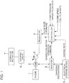
- the controller 4 carries out the calculation and control operations shown in Fig. 2 , that is:
- Fig. 3 shows a predetermined map of the relationship between the charge rate of the electrical storage device 9 and the engine lower limit output.
- the relationship shown in Fig. 3 is previously set as a map and stored in the controller 4.
- the engine lower limit output is set in accordance with the charge rate of the electrical storage device, specifically, so as to be set to a lower value in accordance with the higher charge rate.
- Fig. 4 shows a map in which the engine output permissible increase is added to the engine characteristics indicating the relationship between the engine speed and the fuel flow rate, the map being set and stored in advance in the controller 4.
- Respective five curves C1 to C5 designated by the thick lines in Fig. 4 indicate the relationship between the engine speed and the engine output permissible increase which is set for different fuel flow rates, wherein the higher positioned curve indicates the relationship set for lower fuel flow rate; specifically, the highest curve C1 of the five curves C1 to C5 indicates one set for the lowest fuel flow rate, while the lowest curve C5 indicates one set for the highest fuel flow rate.
- the controller 4 calculates the engine output permissible increase from the determined engine speed and fuel flow rate, on the basis of the map shown in Fig. 4 .
- the engine output permissible increase is Epi1.
- a small fuel flow rate allows a larger engine output permissible increase to be set, because the quality of the combustion in the engine is governed by the engine speed and the fuel flow rate (for example, the higher fuel flow rate is more likely to allow the combustion in the engine to be deteriorated, even at the same engine speed).
- the controller 4 calculates the engine upper limit output by adding the engine output permissible increase calculated in (II) above to the engine lower limit output.
- the controller 4 calculates a target flow rate on the basis of the determined pump pressure and the operation amount of the remote control valve, and, on the basis of this target flow rate, calculates the required-pump-output, that is, an output required of the hydraulic pump 3.
- the controller 4 controls the generator-motor 2. Specifically, in the case of the required pump output in a range no greater than the engine lower limit output, the controller 4 causes the generator-motor 2 to perform an electric generator action to charge the electrical storage device 9; in the case of the required pump output in a range no lower than the engine upper limit output, the controller 4 causes the generator-motor 2 to perform an electric motor action to assist the engine 1; and in the case of the required pump output in a range between the engine lower limit output and the engine upper limit output, the controller 4 sets the output of the generator-motor 2 to zero. The controller 4 thus controls the output of the generator-motor 2 (the generator output or the motor output) so as to keep the required pump output within a range between the engine lower limit output and the engine upper limit output.
- This hybrid construction machine enables the following beneficial effects to be obtained.
- the present invention provides a hybrid construction machine capable of more reliably preventing the combustion in an engine from deterioration due to increase in the required pump output.
- the hybrid construction machine provided by the present invention includes: a hydraulic actuator; a hydraulic pump which discharges hydraulic fluid for driving the hydraulic actuator; a generator-motor which performs an electric generator action of generating electric power and performs an electric motor action of generating motive power; an engine connected to the hydraulic pump and the motor-generator; an electrical storage device; and a controller which causes the generator-motor to perform the electric generator action and charge the electrical storage device and causes the generator-motor to perform the electric motor action by electric power discharged from the electrical storage device to assist the engine.
- the controller causes the generator-motor to start the electric generator action at the time when an output of the engine becomes equal to or greater than a predetermined engine lower limit output, and controls the electric generator action of the generator-motor so as to keep the engine output in a range of no lower than the engine lower limit output.
- the engine lower limit output which is the base for increase in the engine output is previously set and the controller controls the electric generator action of the generator-motor so as to keep the engine output in a range of no lower than the engine lower limit output; this allows the amount of increase (range of change) in the engine output to be restricted, therby restricting the increase in the fuel supply to keep well the combustion in the engine.
- the controller preferably sets the engine lower limit output in accordance with a charge rate of the electrical storage device and sets the engine lower limit output to a lower value as the charge rate reduces higher. Since the high charge rate of the electrical storage device makes the need for charging low, setting the engine lower limit output to a lower value in accordance with the higher charge rate restrains the electrical storage device from unnecessary charge to thereby improve the lifespan thereof.
- the controller preferably sets an engine upper limit output higher than the engine lower limit output, causes the generator-motor to perform the electric motor action when the engine output is greater than the engine upper limit output, and controls the electric motor action of the generator-motor so as to keep the engine output in a range of no more than the engine upper limit output.
- the controller preferably sets an engine upper limit output higher than the engine lower limit output, causes the generator-motor to perform the electric motor action when the engine output is greater than the engine upper limit output, and controls the electric motor action of the generator-motor so as to keep the engine output in a range of no more than the engine upper limit output.
- the controller sets an engine output permissible increase as an amount of increase permissible in the engine output, and calculates the engine upper limit output by adding the engine output permissible increase to the engine lower limit output. This allows the increase in the engine output to be restricted to no more than the permissible increase. Consequently, setting the engine output permissible increase to a suitable value in relation to the combustion state in the engine enables the combustion-deterioration-prevention effect to be further enhanced.
- the controller previously stores a map set in respect of a relationship between an engine speed, a fuel flow rate and the engine-output permissible increase, and sets the engine output permissible increase to a larger value, for a fixed engine speed, as the fuel flow rate becomes smaller, on the basis of the map. Since the greater fuel flow rate is more likely to allow the combustion in the engine to be deteriorated due to increase in the engine output (on contrary, the smaller fuel flow rate is less likely to allow the combustion in the engine to be deteriorated), setting the engine output permissible increase to a smaller value in accordance with the higher fuel flow rate allows the effect of suppressing combustion-deterioration to be enhanced.
- a hybrid construction machine including: a hydraulic actuator; a hydraulic pump which discharges hydraulic fluid for driving the hydraulic actuator; a generator-motor which performs an electric generator action of generating electric power and an electric motor action of generating motive power; an engine connected to the hydraulic pump and the motor-generator; an electrical storage device; and a controller which causes the generator-motor to perform the electric generator action and charge the electrical storage device and causes the generator-motor to perform the electric motor action by electric power discharged from the electrical storage device to assist the engine.
- the controller causes the generator-motor to start the electric generator action when an engine output becomes equal to or greater than a predetermined engine lower limit output, and controls the electric generator action to keep the engine output no lower than the engine lower limit output.
Landscapes
- Engineering & Computer Science (AREA)
- Chemical & Material Sciences (AREA)
- Combustion & Propulsion (AREA)
- Transportation (AREA)
- Mechanical Engineering (AREA)
- Automation & Control Theory (AREA)
- Civil Engineering (AREA)
- General Engineering & Computer Science (AREA)
- Structural Engineering (AREA)
- Mining & Mineral Resources (AREA)
- Power Engineering (AREA)
- Operation Control Of Excavators (AREA)
- Control Of Vehicle Engines Or Engines For Specific Uses (AREA)
- Control Of Eletrric Generators (AREA)
- Hybrid Electric Vehicles (AREA)
Claims (4)
- Hybridbaumaschine mit:einer hydraulischen Betätigungseinrichtung (7);einer Hydraulikpumpe (3), die konfiguriert ist, eine Hydraulikflüssigkeit für ein Antreiben der hydraulischen Betätigungseinrichtung (7) auszustoßen;einem Steuerungsventil (6), das konfiguriert ist, die Hydraulikflüssigkeit, die von der Hydraulikpumpe (3) ausgestoßen wird, der hydraulischen Betätigungseinrichtung (7) zuzuführen, das durch ein entferntes Steuerungsventil betrieben wird;einem Motorgenerator (2), der konfiguriert ist, eine Elektrischer-Generator-Aktion zum Erzeugen einer elektrischen Leistung auszuführen und eine Elektrischer-Motor-Aktion zum Erzeugen einer Antriebskraft auszuführen;einer Kraftmaschine (1), die mit der Hydraulikpumpe (3) und dem Motorgenerator (2) verbunden ist;einer elektrischen Speichervorrichtung (9); undeiner Steuerungseinrichtung (4), die konfiguriert ist, den Motorgenerator (2) zu veranlassen, die Elektrischer-Generator-Aktion auszuführen, um die elektrische Speichervorrichtung (9) aufzuladen, und den Motorgenerator (2) zu veranlassen, die Elektrischer-Motor-Aktion durch eine elektrische Leistung, die von der elektrischen Speichervorrichtung (9) entladen wird, auszuführen, um die Kraftmaschine (1) zu unterstützen,dadurch gekennzeichnet, dassdie Steuerungseinrichtung (4) konfiguriert ist:den Motorgenerator (2) zu veranlassen, die Elektrischer-Generator-Aktion zum Aufladen der elektrischen Speichervorrichtung (9) in einem Fall auszuführen, wenn eine erforderliche Pumpenausgabe, die eine Ausgabe ist, die von der Hydraulikpumpe (3) erfordert wird, nicht größer als eine vorbestimmte Kraftmaschinenuntergrenzenausgabe ist, um eine Kraftmaschinenausgabe in einem Bereich zu halten, der nicht niedriger als die Kraftmaschinenuntergrenzenausgabe ist; undeine Kraftmaschinenobergrenzenausgabe höher als die Kraftmaschinenuntergrenzenausgabe einzustellen und den Motorgenerator (2) zu veranlassen, eine Steuerung der Elektrischer-Motor-Aktion zum Unterstützen der Kraftmaschine (1) in einem Fall auszuführen, wenn die erforderliche Pumpenausgabe nicht niedriger als eine vorbestimmte Kraftmaschinenobergrenzenausgabe ist, um die Kraftmaschinenausgabe in einem Bereich zu halten, der nicht höher als die Kraftmaschinenobergrenzenausgabe ist.
- Hybridbaumaschine nach Anspruch 1, wobei die Steuerungseinrichtung (4) konfiguriert ist, die Kraftmaschinenuntergrenzenausgabe entsprechend einer Ladungsrate der elektrischen Speichervorrichtung (9) einzustellen und die Kraftmaschinenobergrenzenausgabe auf einen niedrigeren Wert entsprechend der höheren Ladungsrate einzustellen.
- Hybridbaumaschine nach Anspruch 1, wobei die Steuerungseinrichtung (4) konfiguriert ist, eine zulässige Kraftmaschinenausgabevergrößerung als einen Betrag einer zulässigen Vergrößerung in der Kraftmaschinenausgabe einzustellen und die Kraftmaschinenobergrenzenausgabe zu berechnen, indem die zulässige Kraftmaschinenausgabevergrößerung zu der Kraftmaschinenuntergrenzenausgabe addiert wird.
- Hybridbaumaschine nach Anspruch 3, wobei die Steuerungseinrichtung (4) konfiguriert ist, eine Abbildung zuvor zu speichern, die in Bezug auf eine Beziehung zwischen einer Kraftmaschinendrehzahl, einer Kraftstoffströmungsrate und der zulässigen Kraftmaschinenausgabevergrößerung eingestellt wird, und die zulässige Kraftmaschinenausgabevergrößerung auf einen größeren Wert für eine fixierte Kraftmaschinendrehzahl entsprechend der kleineren Kraftmaschinenströmungsrate auf der Grundlage der Abbildung einzustellen.
Applications Claiming Priority (1)
| Application Number | Priority Date | Filing Date | Title |
|---|---|---|---|
| JP2012195682A JP6019956B2 (ja) | 2012-09-06 | 2012-09-06 | ハイブリッド建設機械の動力制御装置 |
Publications (3)
| Publication Number | Publication Date |
|---|---|
| EP2705967A2 EP2705967A2 (de) | 2014-03-12 |
| EP2705967A3 EP2705967A3 (de) | 2015-09-23 |
| EP2705967B1 true EP2705967B1 (de) | 2018-03-14 |
Family
ID=49170546
Family Applications (1)
| Application Number | Title | Priority Date | Filing Date |
|---|---|---|---|
| EP13182915.2A Not-in-force EP2705967B1 (de) | 2012-09-06 | 2013-09-04 | Hybride Baumaschine |
Country Status (4)
| Country | Link |
|---|---|
| US (1) | US9013050B2 (de) |
| EP (1) | EP2705967B1 (de) |
| JP (1) | JP6019956B2 (de) |
| CN (1) | CN103661359B (de) |
Families Citing this family (13)
| Publication number | Priority date | Publication date | Assignee | Title |
|---|---|---|---|---|
| JP2883683B2 (ja) | 1990-05-28 | 1999-04-19 | 日清製粉株式会社 | 代用乳の製造法 |
| JP5928065B2 (ja) * | 2012-03-27 | 2016-06-01 | コベルコ建機株式会社 | 制御装置及びこれを備えた建設機械 |
| JP5952897B2 (ja) * | 2012-05-01 | 2016-07-13 | 日立建機株式会社 | ハイブリッド式作業機械 |
| EP2851475B1 (de) * | 2012-05-14 | 2018-07-11 | Hitachi Construction Machinery Co., Ltd. | Hybridbaumaschine |
| JP6204866B2 (ja) * | 2014-03-31 | 2017-09-27 | 日立建機株式会社 | ハイブリッド建設機械 |
| JP6159681B2 (ja) * | 2014-05-07 | 2017-07-05 | 日立建機株式会社 | ハイブリッド作業機械 |
| JP6488759B2 (ja) * | 2015-02-26 | 2019-03-27 | コベルコ建機株式会社 | ハイブリッド建設機械 |
| KR102425742B1 (ko) | 2015-07-03 | 2022-07-28 | 현대두산인프라코어(주) | 건설기계의 제어장치 및 제어방법 |
| JP6419063B2 (ja) * | 2015-12-24 | 2018-11-07 | 日立建機株式会社 | ハイブリッド式作業機械 |
| JP6647963B2 (ja) * | 2016-05-18 | 2020-02-14 | 日立建機株式会社 | 建設機械 |
| US10989052B2 (en) * | 2017-02-14 | 2021-04-27 | Kolberg-Pioneer, Inc. | Apparatus and method for a dual power system |
| DE112017000044B4 (de) * | 2017-04-24 | 2019-09-12 | Komatsu Ltd. | Steuersystem und Arbeitsmaschine |
| GB2592237B (en) * | 2020-02-20 | 2022-07-20 | Terex Gb Ltd | Material processing apparatus with hybrid power system |
Family Cites Families (75)
| Publication number | Priority date | Publication date | Assignee | Title |
|---|---|---|---|---|
| JPS56115428A (en) * | 1980-02-15 | 1981-09-10 | Hitachi Constr Mach Co Ltd | Hydraulic controller |
| US5056312A (en) * | 1988-07-08 | 1991-10-15 | Hitachi Construction Machinery Co., Ltd. | Hydraulic drive system for construction machines |
| US5307631A (en) * | 1991-01-28 | 1994-05-03 | Hitachi Construction Machinery Co., Ltd. | Hydraulic control apparatus for hydraulic construction machine |
| US5638677A (en) * | 1991-03-29 | 1997-06-17 | Hitachi Construction Machinery Co., Ltd. | Control device for hydraulically propelled work vehicle |
| DE4228599B4 (de) * | 1991-09-11 | 2004-08-19 | Bosch Rexroth Ag | Hydraulikkreis für die Versorgung mehrerer, seriell betriebener Verbraucher einer hydraulisch gesteuerten Anlage |
| US6055851A (en) * | 1996-08-12 | 2000-05-02 | Hitachi Construction Machinery Co., Ltd. | Apparatus for diagnosing failure of hydraulic pump for work machine |
| JP3587957B2 (ja) * | 1997-06-12 | 2004-11-10 | 日立建機株式会社 | 建設機械のエンジン制御装置 |
| JP3425730B2 (ja) * | 1998-03-31 | 2003-07-14 | 本田技研工業株式会社 | ハイブリッド車両の制御装置 |
| JP3877901B2 (ja) * | 1999-03-31 | 2007-02-07 | コベルコ建機株式会社 | ショベル |
| JP2000297443A (ja) * | 1999-04-15 | 2000-10-24 | Komatsu Ltd | 建設機械の情報管理装置 |
| WO2001000935A1 (en) * | 1999-06-28 | 2001-01-04 | Kobelco Construction Machinery Co., Ltd. | Drive device of working machine |
| DE60141137D1 (de) * | 2000-05-23 | 2010-03-11 | Kobelco Constr Machinery Ltd | Baumaschine |
| JP4512283B2 (ja) * | 2001-03-12 | 2010-07-28 | 株式会社小松製作所 | ハイブリッド式建設機械 |
| JP3859982B2 (ja) * | 2001-04-27 | 2006-12-20 | 株式会社神戸製鋼所 | ハイブリッド建設機械の電力制御装置 |
| US6735486B2 (en) * | 2001-05-01 | 2004-05-11 | Altec Industries | Side load detection and protection system for rotatable equipment |
| JP2003027985A (ja) * | 2001-07-18 | 2003-01-29 | Hitachi Constr Mach Co Ltd | ハイブリッド建設機械の駆動制御装置、ハイブリッド建設機械及びその駆動制御プログラム |
| JP2004011168A (ja) * | 2002-06-04 | 2004-01-15 | Komatsu Ltd | 建設機械 |
| JP4082935B2 (ja) * | 2002-06-05 | 2008-04-30 | 株式会社小松製作所 | ハイブリッド式建設機械 |
| JP3833573B2 (ja) * | 2002-06-06 | 2006-10-11 | 新キャタピラー三菱株式会社 | ハイブリッド式建設機械 |
| JP4179465B2 (ja) * | 2002-07-31 | 2008-11-12 | 株式会社小松製作所 | 建設機械 |
| JP2004150307A (ja) * | 2002-10-29 | 2004-05-27 | Komatsu Ltd | エンジンの制御装置 |
| JP2004190845A (ja) * | 2002-12-13 | 2004-07-08 | Shin Caterpillar Mitsubishi Ltd | 作業機械の駆動装置 |
| JP2005237178A (ja) * | 2004-02-23 | 2005-09-02 | Kobelco Contstruction Machinery Ltd | 作業機械の動力源装置 |
| JP2005233164A (ja) * | 2004-02-23 | 2005-09-02 | Kobelco Contstruction Machinery Ltd | 作業機械の動力源装置 |
| JP4188902B2 (ja) * | 2004-11-22 | 2008-12-03 | 日立建機株式会社 | 油圧建設機械の制御装置 |
| US7689331B2 (en) * | 2004-12-01 | 2010-03-30 | Ise Corporation | Method of controlling engine stop-start operation for heavy-duty hybrid-electric and hybrid-hydraulic vehicles |
| JP2006177397A (ja) * | 2004-12-21 | 2006-07-06 | Yanmar Co Ltd | 油圧回路 |
| KR20070095381A (ko) * | 2005-01-31 | 2007-09-28 | 스미토모 겐키 세조 가부시키가이샤 | 리프팅 마그넷 사양의 작업기계 |
| WO2006132031A1 (ja) * | 2005-06-06 | 2006-12-14 | Shin Caterpillar Mitsubishi Ltd. | 旋回用駆動装置および作業機械 |
| WO2006132009A1 (ja) * | 2005-06-06 | 2006-12-14 | Shin Caterpillar Mitsubishi Ltd. | 作業機械 |
| US8424302B2 (en) * | 2005-10-28 | 2013-04-23 | Komatsu Ltd. | Control device of engine, control device of engine and hydraulic pump, and control device of engine, hydraulic pump, and generator motor |
| JP4740761B2 (ja) * | 2006-02-14 | 2011-08-03 | 株式会社小松製作所 | エンジン、油圧ポンプおよび発電電動機の制御装置 |
| US7520935B2 (en) * | 2005-12-21 | 2009-04-21 | Johns Manville | Sprayed insulation application system having variably locatable components |
| JP4524679B2 (ja) * | 2006-03-15 | 2010-08-18 | コベルコ建機株式会社 | ハイブリッド建設機械 |
| US7658250B2 (en) * | 2006-09-29 | 2010-02-09 | Caterpillar Inc. | Energy storage and recovery for a tracked machine |
| JP5055948B2 (ja) * | 2006-10-20 | 2012-10-24 | コベルコ建機株式会社 | ハイブリッド作業機械 |
| JP4794468B2 (ja) * | 2007-01-22 | 2011-10-19 | 日立建機株式会社 | 建設機械のポンプ制御装置 |
| EP1961869B1 (de) * | 2007-02-21 | 2018-10-10 | Kobelco Construction Machinery Co., Ltd. | Drehsteuerungsvorrichtung und Arbeitsmaschine damit |
| KR101391104B1 (ko) * | 2007-03-29 | 2014-04-30 | 가부시키가이샤 고마쓰 세이사쿠쇼 | 건설 기계 및 건설 기계의 제어 방법 |
| JP4424370B2 (ja) * | 2007-05-02 | 2010-03-03 | ダイキン工業株式会社 | 油圧ユニット及びそれを備えた建設機械 |
| JP5156312B2 (ja) * | 2007-09-19 | 2013-03-06 | 株式会社小松製作所 | エンジンの制御装置 |
| JP5064160B2 (ja) * | 2007-09-19 | 2012-10-31 | 株式会社小松製作所 | エンジンの制御装置 |
| KR101268849B1 (ko) * | 2007-12-28 | 2013-05-29 | 스미토모 겐키 가부시키가이샤 | 하이브리드식 건설기계 |
| US8505287B1 (en) * | 2008-02-27 | 2013-08-13 | Sturman Industries, Inc. | Micro-hydraulic supply and storage units for operating hydraulic systems |
| JP4633813B2 (ja) * | 2008-03-12 | 2011-02-16 | 住友重機械工業株式会社 | 建設機械の制御方法 |
| US7980073B2 (en) * | 2008-05-08 | 2011-07-19 | Caterpillar Inc. | Hybrid system for a powertrain and hydraulic system |
| JP5090527B2 (ja) * | 2008-05-29 | 2012-12-05 | 住友建機株式会社 | 旋回駆動制御装置及びこれを含む建設機械 |
| KR101199244B1 (ko) * | 2008-06-27 | 2012-11-09 | 스미토모 겐키 가부시키가이샤 | 하이브리드식 건설기계 |
| JP4609567B2 (ja) * | 2008-10-29 | 2011-01-12 | コベルコ建機株式会社 | ハイブリッド作業機械 |
| CN102209655B (zh) * | 2008-11-10 | 2015-05-06 | 住友重机械工业株式会社 | 混合式施工机械 |
| US8639404B2 (en) * | 2008-11-18 | 2014-01-28 | Sumitom Heavy Industries, Ltd. | Working machine |
| JP5401992B2 (ja) * | 2009-01-06 | 2014-01-29 | コベルコ建機株式会社 | ハイブリッド作業機械の動力源装置 |
| KR101334234B1 (ko) * | 2009-06-19 | 2013-11-29 | 스미도모쥬기가이고교 가부시키가이샤 | 하이브리드형 건설기계 및 하이브리드형 건설기계의 제어방법 |
| JP5198661B2 (ja) * | 2009-06-25 | 2013-05-15 | 住友重機械工業株式会社 | ハイブリッド型作業機械及び作業機械の制御方法 |
| JP4941539B2 (ja) * | 2009-11-17 | 2012-05-30 | 株式会社豊田自動織機 | 荷役車両の駆動制御装置 |
| JP5703587B2 (ja) * | 2010-04-14 | 2015-04-22 | コベルコ建機株式会社 | ハイブリッド作業機械 |
| JP5665874B2 (ja) * | 2010-10-06 | 2015-02-04 | 住友重機械工業株式会社 | ハイブリッド型作業機械及びその制御方法 |
| JP2012154092A (ja) * | 2011-01-26 | 2012-08-16 | Kobelco Contstruction Machinery Ltd | ハイブリッド建設機械 |
| CN102971542B (zh) * | 2011-02-03 | 2015-11-25 | 日立建机株式会社 | 作业机械的动力再生装置 |
| JP5509433B2 (ja) * | 2011-03-22 | 2014-06-04 | 日立建機株式会社 | ハイブリッド式建設機械及びこれに用いる補助制御装置 |
| JP5416158B2 (ja) * | 2011-03-31 | 2014-02-12 | 株式会社小松製作所 | 発電電動機および作業機械 |
| JP5389100B2 (ja) * | 2011-04-19 | 2014-01-15 | 日立建機株式会社 | 建設機械の電動駆動装置 |
| JP5562288B2 (ja) * | 2011-05-25 | 2014-07-30 | 日立建機株式会社 | 建設機械の電動駆動装置 |
| JP5559742B2 (ja) * | 2011-05-25 | 2014-07-23 | 日立建機株式会社 | 建設機械の電動駆動装置 |
| JP5653844B2 (ja) * | 2011-06-07 | 2015-01-14 | 住友建機株式会社 | ショベル |
| KR101928597B1 (ko) * | 2011-06-15 | 2018-12-12 | 히다찌 겐끼 가부시키가이샤 | 작업 기계의 동력 회생 장치 |
| US8606448B2 (en) * | 2011-06-29 | 2013-12-10 | Caterpillar Inc. | System and method for managing power in machine having electric and/or hydraulic devices |
| US8909434B2 (en) * | 2011-06-29 | 2014-12-09 | Caterpillar, Inc. | System and method for controlling power in machine having electric and/or hydraulic devices |
| WO2013035815A1 (ja) * | 2011-09-09 | 2013-03-14 | 住友重機械工業株式会社 | ショベル及びショベルの制御方法 |
| JP5841399B2 (ja) * | 2011-10-14 | 2016-01-13 | 日立建機株式会社 | ハイブリッド式建設機械及びその制御方法 |
| KR101991983B1 (ko) * | 2011-12-28 | 2019-06-21 | 히다찌 겐끼 가부시키가이샤 | 작업 기계의 동력 회생 장치 및 작업 기계 |
| JP5247899B1 (ja) * | 2012-02-15 | 2013-07-24 | 株式会社小松製作所 | 蓄電器の充放電制御装置、蓄電器の充放電制御方法、および蓄電器の充放電制御装置を備えたハイブリッド作業機械 |
| KR101608264B1 (ko) * | 2012-03-28 | 2016-04-01 | 가부시끼 가이샤 구보다 | 하이브리드 작업차 |
| EP2851475B1 (de) * | 2012-05-14 | 2018-07-11 | Hitachi Construction Machinery Co., Ltd. | Hybridbaumaschine |
| JP6051857B2 (ja) * | 2012-12-28 | 2016-12-27 | コベルコ建機株式会社 | 建設機械 |
-
2012
- 2012-09-06 JP JP2012195682A patent/JP6019956B2/ja not_active Expired - Fee Related
-
2013
- 2013-09-03 US US14/016,468 patent/US9013050B2/en not_active Expired - Fee Related
- 2013-09-04 EP EP13182915.2A patent/EP2705967B1/de not_active Not-in-force
- 2013-09-06 CN CN201310404107.8A patent/CN103661359B/zh not_active Expired - Fee Related
Non-Patent Citations (1)
| Title |
|---|
| None * |
Also Published As
| Publication number | Publication date |
|---|---|
| CN103661359A (zh) | 2014-03-26 |
| EP2705967A2 (de) | 2014-03-12 |
| US20140062096A1 (en) | 2014-03-06 |
| EP2705967A3 (de) | 2015-09-23 |
| CN103661359B (zh) | 2017-06-09 |
| JP2014051795A (ja) | 2014-03-20 |
| JP6019956B2 (ja) | 2016-11-02 |
| US9013050B2 (en) | 2015-04-21 |
Similar Documents
| Publication | Publication Date | Title |
|---|---|---|
| EP2705967B1 (de) | Hybride Baumaschine | |
| US8548661B2 (en) | Hybrid working machine and controlling method thereof | |
| US9671763B2 (en) | Device for controlling construction machinery | |
| EP1834854B1 (de) | Hybride Baumaschine | |
| EP2851475B1 (de) | Hybridbaumaschine | |
| US8424302B2 (en) | Control device of engine, control device of engine and hydraulic pump, and control device of engine, hydraulic pump, and generator motor | |
| US8534264B2 (en) | Engine control apparatus | |
| CN103080430B (zh) | 混合建筑机械 | |
| US9574327B2 (en) | Hybrid construction machinery | |
| JP5225779B2 (ja) | 充放電制御方法 | |
| US9567916B2 (en) | Engine control apparatus and construction machine | |
| EP2770119B1 (de) | Hydraulische arbeitsmaschine mit hybridantrieb | |
| JPWO2015011809A1 (ja) | ハイブリッド作業機械 | |
| JP2007290607A (ja) | ハイブリッド式作業機械の動力源装置 | |
| CN110382846A (zh) | 混合动力作业机械 | |
| US10458097B2 (en) | Hybrid work machine | |
| JP2012233312A (ja) | ハイブリッド作業機械 | |
| JP2017016777A (ja) | ハイブリッド建設機械の制御システム及び制御方法 | |
| JP6232875B2 (ja) | ハイブリッド建設機械の動力制御装置 |
Legal Events
| Date | Code | Title | Description |
|---|---|---|---|
| PUAI | Public reference made under article 153(3) epc to a published international application that has entered the european phase |
Free format text: ORIGINAL CODE: 0009012 |
|
| AK | Designated contracting states |
Kind code of ref document: A2 Designated state(s): AL AT BE BG CH CY CZ DE DK EE ES FI FR GB GR HR HU IE IS IT LI LT LU LV MC MK MT NL NO PL PT RO RS SE SI SK SM TR |
|
| AX | Request for extension of the european patent |
Extension state: BA ME |
|
| PUAL | Search report despatched |
Free format text: ORIGINAL CODE: 0009013 |
|
| AK | Designated contracting states |
Kind code of ref document: A3 Designated state(s): AL AT BE BG CH CY CZ DE DK EE ES FI FR GB GR HR HU IE IS IT LI LT LU LV MC MK MT NL NO PL PT RO RS SE SI SK SM TR |
|
| AX | Request for extension of the european patent |
Extension state: BA ME |
|
| RIC1 | Information provided on ipc code assigned before grant |
Ipc: B60K 6/485 20071001AFI20150818BHEP Ipc: B60W 10/08 20060101ALI20150818BHEP Ipc: B60W 20/00 20060101ALI20150818BHEP Ipc: B60W 10/06 20060101ALI20150818BHEP Ipc: B60W 10/30 20060101ALI20150818BHEP |
|
| 17P | Request for examination filed |
Effective date: 20160322 |
|
| RBV | Designated contracting states (corrected) |
Designated state(s): AL AT BE BG CH CY CZ DE DK EE ES FI FR GB GR HR HU IE IS IT LI LT LU LV MC MK MT NL NO PL PT RO RS SE SI SK SM TR |
|
| 17Q | First examination report despatched |
Effective date: 20161220 |
|
| GRAP | Despatch of communication of intention to grant a patent |
Free format text: ORIGINAL CODE: EPIDOSNIGR1 |
|
| INTG | Intention to grant announced |
Effective date: 20171013 |
|
| GRAS | Grant fee paid |
Free format text: ORIGINAL CODE: EPIDOSNIGR3 |
|
| GRAA | (expected) grant |
Free format text: ORIGINAL CODE: 0009210 |
|
| AK | Designated contracting states |
Kind code of ref document: B1 Designated state(s): AL AT BE BG CH CY CZ DE DK EE ES FI FR GB GR HR HU IE IS IT LI LT LU LV MC MK MT NL NO PL PT RO RS SE SI SK SM TR |
|
| REG | Reference to a national code |
Ref country code: GB Ref legal event code: FG4D |
|
| REG | Reference to a national code |
Ref country code: CH Ref legal event code: EP Ref country code: AT Ref legal event code: REF Ref document number: 978508 Country of ref document: AT Kind code of ref document: T Effective date: 20180315 |
|
| REG | Reference to a national code |
Ref country code: IE Ref legal event code: FG4D |
|
| REG | Reference to a national code |
Ref country code: DE Ref legal event code: R096 Ref document number: 602013034351 Country of ref document: DE |
|
| REG | Reference to a national code |
Ref country code: NL Ref legal event code: MP Effective date: 20180314 |
|
| REG | Reference to a national code |
Ref country code: LT Ref legal event code: MG4D |
|
| PG25 | Lapsed in a contracting state [announced via postgrant information from national office to epo] |
Ref country code: ES Free format text: LAPSE BECAUSE OF FAILURE TO SUBMIT A TRANSLATION OF THE DESCRIPTION OR TO PAY THE FEE WITHIN THE PRESCRIBED TIME-LIMIT Effective date: 20180314 Ref country code: HR Free format text: LAPSE BECAUSE OF FAILURE TO SUBMIT A TRANSLATION OF THE DESCRIPTION OR TO PAY THE FEE WITHIN THE PRESCRIBED TIME-LIMIT Effective date: 20180314 Ref country code: LT Free format text: LAPSE BECAUSE OF FAILURE TO SUBMIT A TRANSLATION OF THE DESCRIPTION OR TO PAY THE FEE WITHIN THE PRESCRIBED TIME-LIMIT Effective date: 20180314 Ref country code: NO Free format text: LAPSE BECAUSE OF FAILURE TO SUBMIT A TRANSLATION OF THE DESCRIPTION OR TO PAY THE FEE WITHIN THE PRESCRIBED TIME-LIMIT Effective date: 20180614 Ref country code: FI Free format text: LAPSE BECAUSE OF FAILURE TO SUBMIT A TRANSLATION OF THE DESCRIPTION OR TO PAY THE FEE WITHIN THE PRESCRIBED TIME-LIMIT Effective date: 20180314 Ref country code: CY Free format text: LAPSE BECAUSE OF FAILURE TO SUBMIT A TRANSLATION OF THE DESCRIPTION OR TO PAY THE FEE WITHIN THE PRESCRIBED TIME-LIMIT Effective date: 20180314 |
|
| REG | Reference to a national code |
Ref country code: AT Ref legal event code: MK05 Ref document number: 978508 Country of ref document: AT Kind code of ref document: T Effective date: 20180314 |
|
| PG25 | Lapsed in a contracting state [announced via postgrant information from national office to epo] |
Ref country code: LV Free format text: LAPSE BECAUSE OF FAILURE TO SUBMIT A TRANSLATION OF THE DESCRIPTION OR TO PAY THE FEE WITHIN THE PRESCRIBED TIME-LIMIT Effective date: 20180314 Ref country code: SE Free format text: LAPSE BECAUSE OF FAILURE TO SUBMIT A TRANSLATION OF THE DESCRIPTION OR TO PAY THE FEE WITHIN THE PRESCRIBED TIME-LIMIT Effective date: 20180314 Ref country code: GR Free format text: LAPSE BECAUSE OF FAILURE TO SUBMIT A TRANSLATION OF THE DESCRIPTION OR TO PAY THE FEE WITHIN THE PRESCRIBED TIME-LIMIT Effective date: 20180615 Ref country code: RS Free format text: LAPSE BECAUSE OF FAILURE TO SUBMIT A TRANSLATION OF THE DESCRIPTION OR TO PAY THE FEE WITHIN THE PRESCRIBED TIME-LIMIT Effective date: 20180314 Ref country code: BG Free format text: LAPSE BECAUSE OF FAILURE TO SUBMIT A TRANSLATION OF THE DESCRIPTION OR TO PAY THE FEE WITHIN THE PRESCRIBED TIME-LIMIT Effective date: 20180614 |
|
| REG | Reference to a national code |
Ref country code: FR Ref legal event code: PLFP Year of fee payment: 6 |
|
| PG25 | Lapsed in a contracting state [announced via postgrant information from national office to epo] |
Ref country code: RO Free format text: LAPSE BECAUSE OF FAILURE TO SUBMIT A TRANSLATION OF THE DESCRIPTION OR TO PAY THE FEE WITHIN THE PRESCRIBED TIME-LIMIT Effective date: 20180314 Ref country code: AL Free format text: LAPSE BECAUSE OF FAILURE TO SUBMIT A TRANSLATION OF THE DESCRIPTION OR TO PAY THE FEE WITHIN THE PRESCRIBED TIME-LIMIT Effective date: 20180314 Ref country code: PL Free format text: LAPSE BECAUSE OF FAILURE TO SUBMIT A TRANSLATION OF THE DESCRIPTION OR TO PAY THE FEE WITHIN THE PRESCRIBED TIME-LIMIT Effective date: 20180314 Ref country code: EE Free format text: LAPSE BECAUSE OF FAILURE TO SUBMIT A TRANSLATION OF THE DESCRIPTION OR TO PAY THE FEE WITHIN THE PRESCRIBED TIME-LIMIT Effective date: 20180314 Ref country code: NL Free format text: LAPSE BECAUSE OF FAILURE TO SUBMIT A TRANSLATION OF THE DESCRIPTION OR TO PAY THE FEE WITHIN THE PRESCRIBED TIME-LIMIT Effective date: 20180314 |
|
| PG25 | Lapsed in a contracting state [announced via postgrant information from national office to epo] |
Ref country code: SM Free format text: LAPSE BECAUSE OF FAILURE TO SUBMIT A TRANSLATION OF THE DESCRIPTION OR TO PAY THE FEE WITHIN THE PRESCRIBED TIME-LIMIT Effective date: 20180314 Ref country code: AT Free format text: LAPSE BECAUSE OF FAILURE TO SUBMIT A TRANSLATION OF THE DESCRIPTION OR TO PAY THE FEE WITHIN THE PRESCRIBED TIME-LIMIT Effective date: 20180314 Ref country code: CZ Free format text: LAPSE BECAUSE OF FAILURE TO SUBMIT A TRANSLATION OF THE DESCRIPTION OR TO PAY THE FEE WITHIN THE PRESCRIBED TIME-LIMIT Effective date: 20180314 Ref country code: SK Free format text: LAPSE BECAUSE OF FAILURE TO SUBMIT A TRANSLATION OF THE DESCRIPTION OR TO PAY THE FEE WITHIN THE PRESCRIBED TIME-LIMIT Effective date: 20180314 |
|
| REG | Reference to a national code |
Ref country code: DE Ref legal event code: R097 Ref document number: 602013034351 Country of ref document: DE |
|
| PG25 | Lapsed in a contracting state [announced via postgrant information from national office to epo] |
Ref country code: PT Free format text: LAPSE BECAUSE OF FAILURE TO SUBMIT A TRANSLATION OF THE DESCRIPTION OR TO PAY THE FEE WITHIN THE PRESCRIBED TIME-LIMIT Effective date: 20180716 |
|
| PLBE | No opposition filed within time limit |
Free format text: ORIGINAL CODE: 0009261 |
|
| STAA | Information on the status of an ep patent application or granted ep patent |
Free format text: STATUS: NO OPPOSITION FILED WITHIN TIME LIMIT |
|
| PG25 | Lapsed in a contracting state [announced via postgrant information from national office to epo] |
Ref country code: DK Free format text: LAPSE BECAUSE OF FAILURE TO SUBMIT A TRANSLATION OF THE DESCRIPTION OR TO PAY THE FEE WITHIN THE PRESCRIBED TIME-LIMIT Effective date: 20180314 |
|
| REG | Reference to a national code |
Ref country code: CH Ref legal event code: PK Free format text: BERICHTIGUNGEN |
|
| RIC2 | Information provided on ipc code assigned after grant |
Ipc: B60W 10/30 20060101ALI20150818BHEP Ipc: B60W 10/08 20060101ALI20150818BHEP Ipc: B60W 10/06 20060101ALI20150818BHEP Ipc: B60K 6/485 20071001AFI20150818BHEP Ipc: B60W 20/00 20160101ALI20150818BHEP |
|
| 26N | No opposition filed |
Effective date: 20181217 |
|
| PG25 | Lapsed in a contracting state [announced via postgrant information from national office to epo] |
Ref country code: SI Free format text: LAPSE BECAUSE OF FAILURE TO SUBMIT A TRANSLATION OF THE DESCRIPTION OR TO PAY THE FEE WITHIN THE PRESCRIBED TIME-LIMIT Effective date: 20180314 |
|
| PG25 | Lapsed in a contracting state [announced via postgrant information from national office to epo] |
Ref country code: MC Free format text: LAPSE BECAUSE OF FAILURE TO SUBMIT A TRANSLATION OF THE DESCRIPTION OR TO PAY THE FEE WITHIN THE PRESCRIBED TIME-LIMIT Effective date: 20180314 |
|
| REG | Reference to a national code |
Ref country code: CH Ref legal event code: PL |
|
| REG | Reference to a national code |
Ref country code: BE Ref legal event code: MM Effective date: 20180930 |
|
| REG | Reference to a national code |
Ref country code: IE Ref legal event code: MM4A |
|
| PG25 | Lapsed in a contracting state [announced via postgrant information from national office to epo] |
Ref country code: LU Free format text: LAPSE BECAUSE OF NON-PAYMENT OF DUE FEES Effective date: 20180904 |
|
| PG25 | Lapsed in a contracting state [announced via postgrant information from national office to epo] |
Ref country code: IE Free format text: LAPSE BECAUSE OF NON-PAYMENT OF DUE FEES Effective date: 20180904 |
|
| PG25 | Lapsed in a contracting state [announced via postgrant information from national office to epo] |
Ref country code: LI Free format text: LAPSE BECAUSE OF NON-PAYMENT OF DUE FEES Effective date: 20180930 Ref country code: BE Free format text: LAPSE BECAUSE OF NON-PAYMENT OF DUE FEES Effective date: 20180930 Ref country code: CH Free format text: LAPSE BECAUSE OF NON-PAYMENT OF DUE FEES Effective date: 20180930 |
|
| PG25 | Lapsed in a contracting state [announced via postgrant information from national office to epo] |
Ref country code: MT Free format text: LAPSE BECAUSE OF NON-PAYMENT OF DUE FEES Effective date: 20180904 |
|
| PG25 | Lapsed in a contracting state [announced via postgrant information from national office to epo] |
Ref country code: TR Free format text: LAPSE BECAUSE OF FAILURE TO SUBMIT A TRANSLATION OF THE DESCRIPTION OR TO PAY THE FEE WITHIN THE PRESCRIBED TIME-LIMIT Effective date: 20180314 |
|
| PG25 | Lapsed in a contracting state [announced via postgrant information from national office to epo] |
Ref country code: HU Free format text: LAPSE BECAUSE OF FAILURE TO SUBMIT A TRANSLATION OF THE DESCRIPTION OR TO PAY THE FEE WITHIN THE PRESCRIBED TIME-LIMIT; INVALID AB INITIO Effective date: 20130904 |
|
| PG25 | Lapsed in a contracting state [announced via postgrant information from national office to epo] |
Ref country code: MK Free format text: LAPSE BECAUSE OF NON-PAYMENT OF DUE FEES Effective date: 20180314 |
|
| PG25 | Lapsed in a contracting state [announced via postgrant information from national office to epo] |
Ref country code: IS Free format text: LAPSE BECAUSE OF FAILURE TO SUBMIT A TRANSLATION OF THE DESCRIPTION OR TO PAY THE FEE WITHIN THE PRESCRIBED TIME-LIMIT Effective date: 20180714 |
|
| PGFP | Annual fee paid to national office [announced via postgrant information from national office to epo] |
Ref country code: IT Payment date: 20210811 Year of fee payment: 9 Ref country code: FR Payment date: 20210812 Year of fee payment: 9 |
|
| PGFP | Annual fee paid to national office [announced via postgrant information from national office to epo] |
Ref country code: GB Payment date: 20210728 Year of fee payment: 9 |
|
| PGFP | Annual fee paid to national office [announced via postgrant information from national office to epo] |
Ref country code: DE Payment date: 20220621 Year of fee payment: 10 |
|
| GBPC | Gb: european patent ceased through non-payment of renewal fee |
Effective date: 20220904 |
|
| PG25 | Lapsed in a contracting state [announced via postgrant information from national office to epo] |
Ref country code: FR Free format text: LAPSE BECAUSE OF NON-PAYMENT OF DUE FEES Effective date: 20220930 |
|
| PG25 | Lapsed in a contracting state [announced via postgrant information from national office to epo] |
Ref country code: IT Free format text: LAPSE BECAUSE OF NON-PAYMENT OF DUE FEES Effective date: 20220904 Ref country code: GB Free format text: LAPSE BECAUSE OF NON-PAYMENT OF DUE FEES Effective date: 20220904 |
|
| REG | Reference to a national code |
Ref country code: DE Ref legal event code: R119 Ref document number: 602013034351 Country of ref document: DE |
|
| PG25 | Lapsed in a contracting state [announced via postgrant information from national office to epo] |
Ref country code: DE Free format text: LAPSE BECAUSE OF NON-PAYMENT OF DUE FEES Effective date: 20240403 |