EP2705971A2 - Prise de courant - Google Patents
Prise de courant Download PDFInfo
- Publication number
- EP2705971A2 EP2705971A2 EP13183805.4A EP13183805A EP2705971A2 EP 2705971 A2 EP2705971 A2 EP 2705971A2 EP 13183805 A EP13183805 A EP 13183805A EP 2705971 A2 EP2705971 A2 EP 2705971A2
- Authority
- EP
- European Patent Office
- Prior art keywords
- pantograph
- current collector
- bracket
- piston
- brackets
- Prior art date
- Legal status (The legal status is an assumption and is not a legal conclusion. Google has not performed a legal analysis and makes no representation as to the accuracy of the status listed.)
- Granted
Links
Images


Classifications
-
- B—PERFORMING OPERATIONS; TRANSPORTING
- B60—VEHICLES IN GENERAL
- B60L—PROPULSION OF ELECTRICALLY-PROPELLED VEHICLES; SUPPLYING ELECTRIC POWER FOR AUXILIARY EQUIPMENT OF ELECTRICALLY-PROPELLED VEHICLES; ELECTRODYNAMIC BRAKE SYSTEMS FOR VEHICLES IN GENERAL; MAGNETIC SUSPENSION OR LEVITATION FOR VEHICLES; MONITORING OPERATING VARIABLES OF ELECTRICALLY-PROPELLED VEHICLES; ELECTRIC SAFETY DEVICES FOR ELECTRICALLY-PROPELLED VEHICLES
- B60L5/00—Current collectors for power supply lines of electrically-propelled vehicles
- B60L5/18—Current collectors for power supply lines of electrically-propelled vehicles using bow-type collectors in contact with trolley wire
- B60L5/19—Current collectors for power supply lines of electrically-propelled vehicles using bow-type collectors in contact with trolley wire using arrangements for effecting collector movement transverse to the direction of vehicle motion
-
- B—PERFORMING OPERATIONS; TRANSPORTING
- B60—VEHICLES IN GENERAL
- B60L—PROPULSION OF ELECTRICALLY-PROPELLED VEHICLES; SUPPLYING ELECTRIC POWER FOR AUXILIARY EQUIPMENT OF ELECTRICALLY-PROPELLED VEHICLES; ELECTRODYNAMIC BRAKE SYSTEMS FOR VEHICLES IN GENERAL; MAGNETIC SUSPENSION OR LEVITATION FOR VEHICLES; MONITORING OPERATING VARIABLES OF ELECTRICALLY-PROPELLED VEHICLES; ELECTRIC SAFETY DEVICES FOR ELECTRICALLY-PROPELLED VEHICLES
- B60L2200/00—Type of vehicles
- B60L2200/26—Rail vehicles
Definitions
- the invention relates to a current collector according to the features of patent claim 1.
- Pantographs are used to transfer electrical energy from a fixed, current-carrying overhead line to electrical components of the powered vehicle. Such pantographs are found especially on track-bound vehicles. In modern rail vehicles, the so-called single-member pantograph is usually used due to the lighter construction.
- the height adjustment of the pantograph is electrically, hydraulically or pneumatically with respect to the vehicle-mounted base frame of the pantograph.
- On the base frame is a rod work consisting of forearm, handlebar and upper arm and on this arranged a pantograph rocker with a Schleifraunan extract for contacting with the contact wire of the overhead line.
- one or more wiper strips may be provided.
- a particular challenge with regard to the design of pantographs for cross-border rail transport is the adaptation to the different gauge sections, because a pantograph is preferably to allow the retrofitting of vehicles that can be approved, for example, in Germany and the neighboring German countries.
- compliance with relevant European standards relating to the interaction between the pantograph and the overhead contact line (EN 50367) is decisive.
- the gauge gauge EN 50367 B2 would have to be complied with for Switzerland, while gauge gauge EN 50367 B3 must be complied with for Germany and Austria.
- the profiles differ from each other both in terms of the rocker width and as regards the profile profile and the isolated lengths of the horns.
- pantograph rocker An essential element of the pantograph rocker is a transverse to the direction of travel bracket assembly, the end has runners. These are downwards, ie away from the contact wire and following the profile course, bent. By means of the runners it is prevented that the pantograph hooks on the overhead line, if the overhead line should leave the Schleifrucn Scheme by lateral deflection. Due to different power transmission systems and different widths of the pantograph heads are required. In Switzerland, for example, the required width is 1,450 mm, whereas in Germany a rocker width of 1,950 mm is required. There are countries with different clearance profiles within the country as well as other standards with widths of 1,600 mm and 1,800 mm. In cross-border traffic Rail vehicles were therefore equipped with different pantographs for the respective power transmission systems.
- the DE 199 14 566 A1 proposes for this reason a pantograph for multi-system rail vehicles, in which two separate, spaced apart in the longitudinal direction of the vehicle and extending transversely to him bracket, each with a lateral Auflaufhorn are arranged on a rocker, wherein the two Auflauf technoner have to opposite sides of the vehicle and wherein the brackets and thus the two overhead horns by means of a respective hydraulic or pneumatic adjusting device opposite to each other transversely to the direction of travel are displaced.
- two spaced apart in the longitudinal direction of the vehicle, arranged on the rocker wiper slats by a respective other hydraulic or pneumatic adjusting device opposite to each other transversely to the direction of travel displaced. In this way, the adaptation to different widths of the power transmission systems takes place.
- a pantograph rocker which comprises an adjustable bracket assembly whose End technologicalner (Bügelauflauf technoner) are each displaced by means of two pairs of levers.
- the End workshopner determine both in the pivoted position and in the pivoted position with the profile of the pantograph rocker.
- the end horns have at their ends an isolation area that remains the same on a horizontal plane projected insulation length, regardless of whether End stealner swung or swung.
- the desired width adaptation to clearance profiles of different power transmission systems takes place by pivoting, these generally also require different lengths of insulation below the iron-earner horns.
- This second criterion can not be met with the solution described for each power transmission system, since only a single projected insulation length is available.
- the optimal utilization of the given clearance gauge eg according to EN 50367-B3 is by the kinematics of the lever assembly difficult because it can come by pivoting to an inclination of the lower ends of the ironing horns.
- the rocker according to the invention is intended to comprise at least one fixed contact piece as well as a contact strip adjustable perpendicular to the longitudinal axis of the vehicle.
- the adjustable grinding piece consists of two grinding piece sections, which are arranged so as to be spaced apart from each other.
- the sliding piece sections should be arranged symmetrically to a line of symmetry intersecting the fixed grinding piece.
- the adjustable sliding piece sections themselves may have runners at the ends.
- the invention is therefore based on the object of disclosing a width-adjustable current collector, which is suitable due to its special geometric design, the requirements of the different conventional clearance profiles in cross-border Traffic, especially in Europe, eg in Germany, Austria, Switzerland and France.
- a current collector rocker which has at least one arranged transversely to the direction of sliding strip.
- the pantograph rocker is provided with transversely arranged to the direction of ironing, which have at their ends Bügelauflauf technoner.
- the current collector rocker is adjustable in width.
- the sanding strip itself has Schleifrucnauflauf technoner at their ends.
- the brackets are guided and supported at least in the retracted position only by the at least one adjusting device. In the retracted position, the bracket is subject to less load than in the extended position. Therefore, with a correspondingly stable adjusting device, an additional guidance of the bracket is not required. In addition to the weight savings is a further advantage that the bracket can not freeze because he prefers to come into contact with any other supporting components.
- the adjusting device fulfills several functions in the invention: The main function is the displacement of the bracket. Since the bracket is attached only to the adjusting device as a supporting component, the adjusting device also has the function of a carrier. In addition, because the actuator serves to displace at the same time, it also fulfills the guiding function which in the prior art makes partial lever arrangements necessary. Finally, the adjusting device also serves to lock the bracket in the selected position and to fix it spatially relative to the grinding strips in order to avoid an undesired adjustment.
- the adjusting device is in particular a pneumatically or hydraulically driven actuator.
- the adjusting device is preferably linearly effective.
- the adjusting device may be formed by one or more lifting cylinders.
- bracket is guided and supported not only in the retracted position but also in the extended position exclusively by the actuator, which is associated with the same advantages as have been described above.
- At least one support bearing can be provided.
- the support bearing can at the Current collector rocker be attached, especially on the rocker frame.
- a rigidly connected to the bracket or arranged on the bracket contact surface is provided, which rests in the extended position of the bracket on a contact surface of the support bearing.
- the support bearing is intended to prevent the straps bending too far under their own weight or under a force acting from outside on the brackets, or that the straps are deflected too far. It is a multi-sided support possible, with a support from below brings the greatest benefits.
- the brackets preferably reach only in their outer position in contact with the support bearing.
- the support bearing is preferably arranged as far as possible from the adjusting device in order to provide optimum support for the hoops via bearing points located far apart from each other.
- the support bearings are located on the Schleifraunhalter.
- the support bearing preferably has the smallest possible contact surface with the bracket in order to minimize the risk of icing. It can therefore be a linear or even a one-time support, which allows easy breakaway. It is in the support bearing is not an additional guide, which leads between the retracted and the extended position, so that the bracket is guided until reaching the support bearing only by the adjusting device.
- the support bearing is formed in a preferred embodiment as part of a bearing assembly either as a receptacle, in particular as a bolt receptacle or as a bearing pin for the mutual operative engagement with a complementary, arranged on the bracket counterpart. That is, the fixed part of the bearing assembly may be formed as a nut piece or as a father piece, matching the respective counterpart.
- a bearing pin according to the invention preferably has a circular cross-section. Its cross-section can also be out of round or polygonal.
- a bolt receiving in the form of a bore of the bearing pin is received with sufficient clearance to a capillary action for moisture to avoid and to minimize the risk of freezing.
- the game must not be too high in the vertical direction, so that the straps do not bend too far down.
- the difference in diameter from bolt to bolt receptacle in the order of 5/10 mm should not fall below or be exceeded by 20/10 mm.
- the support bearing can serve as a centering in accordance with a further preferred embodiment by the bracket is aligned upon extension through the support bearing to a predetermined axis.
- the bearing pin can be configured as a centering pin, in particular its tip can be conical, so that it has an insertion bevel.
- the receptacle forming the support bearing may taper in the take-up direction, i. The distance between opposing surfaces of the support bearing can be reduced in the recording direction.
- the bearing pin and / or the support bearing may have a material with hydrophobic and / or dirt-repellent properties at least in the area of their mutual contact surfaces.
- Hydrophobic refers to materials whose contact angle is greater than 90 °.
- the contact surfaces may consist of different materials, preferably of at least one material with a low coefficient of friction, in particular of plastic.
- At least one of the contact surfaces may preferably consist of polytetrafluoroethylene (PTFE).
- PTFE polytetrafluoroethylene
- PTFE polytetrafluoroethylene
- the bearing pin may consist entirely of PTFE or a PTFE-containing composite material, or be coated with PTFE. This applies correspondingly to the bearing receptacle, in which in particular a bearing bush made of a hydrophobic plastic is used.
- the Contact surfaces can also be provided with an ice-adhering repellent surface structure.
- the thermal conductivity of the materials of the contact surfaces, but in particular the entire bearing assembly is low. In particular, it is lower than the thermal conductivity of metals, ie less than 10 W / mK, in particular less than 2 W / mK.
- the water absorption should be low, in particular less than 0.1 wt .-%, preferably less than 0.01 wt .-%.
- polymeric plain bearing materials such as those offered under the trade name iglidur® J by igus GmbH, 51147 Cologne, Germany, are suitable.
- the support bearing in the receiving direction and opposite to the receiving direction openings is not designed as a blind hole but as a through hole.
- the advantage is that any deposits are displaced from the through hole when inserting the bearing pin and can not clog the bolt holder as in a blind hole.
- the bearing pin can protrude for this purpose, a piece of the bolt holder.
- When retracting the bolt any buildup of the bolt are also stripped, so that the retraction and extension of the bracket also leads to a self-cleaning of the bearing assembly.
- the bearing pin is interchangeable for ease of maintenance.
- the mutual contact surfaces are small. Therefore, the cross sections of bearing pin and support bearing can be small. Due to the small contact surfaces, the breakaway force to be applied during a possible freezing is reduced.
- the inner, adjacent ends of the strap are transverse to the direction of travel directly opposite.
- the ends here between both sides of the two ends are arranged adjusting devices, which are each connected to one of the two brackets.
- This arrangement has the advantage that the ends of the brackets in the retracted position can be very close to each other, so that the straps can be retracted very far so that they do not protrude over the limited of the sanding strip and the Schleifrucnauflauf technicallynern profile.
- the adjusting devices are preferably arranged very close to the brackets, so that no long connecting elements between the actuator and the associated bracket are required. This saves space and weight.
- the height of the pantograph head must not be changed by the additional adjusting devices, as the adjusting devices and the ends of the stirrups are in the same horizontal plane.
- the actuators with the attached brackets are connected to actuator holders. About the governor holder, the weight of the bracket and the adjusting devices is added. They are in turn connected to the spring-mounted grinding bar carriers.
- the actuator holders have a receptacle.
- the ends of the strap can be moved.
- the receptacle is preferably open at the top and has two upwardly pointing legs, which are connected to one another via a web.
- the receptacle is therefore arcuate in cross-section, e.g. U-shaped or V-shaped.
- the actuators are mounted on the lateral legs of the actuator holder.
- the adjusting devices have elongated housings.
- a positioner holder is arranged in the region of the end of a housing.
- two lifting cylinders are fastened by means of the two actuator holder.
- the piston rods of the lifting cylinder are extendable in opposite directions.
- At each of the piston rods is a Attached to the end of a stirrup.
- the connecting element, with which the piston rod is fixed to the bracket, is located at a distance from the inner end face of the bracket, to such an extent that the bracket according to the distance of the connecting element from the end face between the adjusting devices is displaced.
- each bracket has two ends and is therefore guided and held by two adjusting devices.
- implement holders there are four implement holders. These may in turn be connected in pairs, e.g. by extending in the direction of travel cross struts. Further connecting struts extend as longitudinal struts parallel to the grinding bar carriers. In this case, not every actuator holder must be connected to each grinder carrier.
- a power transmission system can be used only with the at least one grinding piece, hereinafter referred to as the main grinding piece, and yet a very good adaptation to different clearance profiles is given.
- the sanding strip can carry a main sanding piece, with supplementary sanding pieces being arranged on the ironing.
- the supplementary grinding pieces are displaceable in opposite directions with respect to the main grinding piece.
- the pneumatic or hydraulic control or the conversion of a pneumatic or hydraulic signal into an electrical signal takes place only in the vehicle itself, where the current applied to the pantograph voltage potential of max. 25 kV rated voltage can not affect the controller.
- clearance gauge is abbreviated to simplify by profile.
- the retracted position means a setting to a width SB1.
- the sanding strip or the main sanding piece and the sanding belt runners determine the profile of the pantograph rocker in the retracted position alone.
- the Bügelauflauf technologicalner are therefore in the retracted position of the bracket upwards or in the direction of the overhead line not on the limited by the contact strip and the Schleifologicalnauflauf technologicalnern profile.
- the main grinding piece and / or the supplementary grinding pieces can be connected to an automatic lowering device (AS or ADD).
- the pneumatic, automatic lowering device is intended to automatically reduce the current collector applied to the contact wire in the event of breakage of the contact pieces and thus avoid consequential damage to the overhead line and the current collector.
- the sliding pieces are each provided with a channel, which is supplied via a piping system with compressed air from the current collector drive. If compressed air escapes from the contact pieces as a result of damage, the lifting drive of the current collector is vented via a quick-release valve. In case of damage, the pantograph is thus disconnected from the overhead contact line by the ADD system.
- An electrical connection of the main grinding piece with the supplementary grinding pieces ensures a good quality of power transmission.
- This electrical connection can preferably be made by means of current strands, the ends of which are fastened on one side to the main grinding piece and on the other hand to the supplementary grinding pieces.
- the current strand ensures, for example, when the current collector is extended, the current flow of the overhead line, which, due to its zigzag-shaped course, can also temporarily only be on the supplementary loop piece. This also ensures that the flow of current does not flow uncontrollably over other, conductive components that are not intended for power transmission.
- the invention does not exclude that instead of current strands other electrical connections partially or completely participate in the power transmission. With appropriate design, a power transmission in the range of guides and bearings is possible.
- the Bügelauflauf technoner the adjustable strap and the fixed Schleifraunauflauf Anlagenner can each have straight sections, each having a measured over the horizontal Auflaufhornwinkel. It is considered advantageous if the Auflaufhornwinkel the Bügelauflauf technologicalner is greater than the Auflaufhornwinkel the Schleifornauflauf technoner. For optimum profile matching, it is considered convenient if the runner horn angle is e.g. at 1450 mm width is 38 ° to 40 °, while the runner angle is e.g. at 1950 mm width is 28 ° to 30 °.
- the effective wiper strip length is composed of the wiper strip and the supplemental wiper pieces, and may be limited to, e.g. 1030 mm be extended.
- the runners are provided with electrically insulated areas.
- the projected on a horizontal plane lengths of Schleifarchnauflauf technoner and the ironing horns are different.
- the insulation determines the usable electrical working width of the pantograph, which goes beyond the pure width of the sanding strip.
- the angles between the main loop and supplementary grinding pieces or between supplementary grinding pieces and the ironing horn must be kept as low as possible in order to minimize lateral forces.
- the angle is called the transition angle. It is an advantage if in one Vertical plane measured transition angle between the supplementary grinding pieces and the supplementary loop pieces bearing bracket horn is ⁇ 30 °. In particular, the transition angle is ⁇ 20 ° or ⁇ 15 °, and preferably ⁇ 10 °.
- the transition angle between the supplementary pieces and the at least one main grinding piece is preferably ⁇ 10 °
- the mass of a pantograph can be divided into three major masses m1, m2 and m3.
- the mass m1 comprises the reduced masses of the rocker, which bear directly on the contact wire and is mainly formed by the mass of the contact strips, the connecting webs between the contact strips, the 50% share of the rocker spring and the share of the current connectors in the rocker area.
- the mass m2 combines all masses acting at the vertex of the apex tube, i. all add-on parts in the area of the apex tube, the remaining portions of current connectors and rocker springs and in addition each 1/4 of the masses of the upper arm and the rocker guide.
- the mass m3 is formed by the vertically oscillating mass of the current collector frame.
- the stirrups together with the additional grinding pieces are part of the masses m1 sprung together.
- the angled lower end is preferably located at the same height as the lower end of the Bügelauflauf Anlagenner, so that the Bügelauflauf Anlagenner in the retracted position and not projecting downwards over the clearance of the Schleifolinnauflauf confusener.
- the length of the ends can be chosen so that the opposite the straight portions of the Schleifraunauflauf technologicalner downwardly angled ends of the Schleifraunauflauf technologicalner extend over a greater height than the corresponding ends of the Bügelauflauf technologicalner, without protruding over the ends of the Bügelauflauf technoner down.
- the greater extent of the lower ends of the Schleifarchnauflauf technologicalner need not necessarily mean that they extend over a longer range in the vertical direction.
- the relatively large radius of 140mm +/- 10mm contact radius on the wiper reaming horns relative to the smaller radius on the buffing horns results in the ends of the wiper casserole horns being more or less tapering off the curved portion of the wiper casserole horns.
- the Bügelauflauf Anlagenner itself can be configured U-shaped. This is to be understood that two arranged on a vehicle side brackets, which are each associated with one of two spaced juxtaposed supplementary sanding pieces are connected to each other via Bügelauflauf Anlagenner. In the plan view from above, this results in a substantially U-shaped course, which satisfies the requirements of the respective clearance profiles in the side view.
- the ironing-up horns may also be configured Y-shaped.
- the two upper arms of the letter Y are connected to the respective adjustable brackets. So there is a V- or U-shaped one Part connected with a one-legged length section. Irrespective of whether the U-shaped or Y-shaped U-shaped horns are configured, there is no difference in adaptation to the respective clearance profiles.
- the radii and transition areas can be selected identically for Y and U-shaped brackets.
- brackets are to be adjustable in the opposite direction to each other, it is appropriate from a control point of view and also for safety reasons to provide position detectors, which are provided for determining the position of the bracket in the lowered and / or raised position of the pantograph.
- the position detectors cooperate in a first embodiment with position sensors, which can be brought in the lowered position of the pantograph rocker in operative engagement with a plurality of position detectors on the base frame.
- the brackets can be locked in the desired position, in particular via pneumatically or hydraulically driven actuators. These may be the adjusting devices themselves.
- the invention also includes the possibility of providing additional actuators, which can be brought into operative engagement with locking means.
- the locking means When the pantograph is in the raised position, the locking means must be locked. This ensures that the bracket in a raised position, ie during operation, can not relocate. But it is also conceivable that the bracket is lowered, because another pantograph is in operation. In this case, the bracket must also be locked in lowered position.
- the invention advantageously provides that an end position of pneumatic actuators without additional sensor means, such as e.g. Roller lever valves is detected.
- the pneumatic adjusting devices are designed for this purpose as double-acting piston-cylinder units.
- the end position of the piston can be detected by two control lines, which are connected to the cylinder.
- the connection of a first control line to the cylinder is positioned so that it is in fluid communication with the piston head space only when the piston is extended.
- the connection of a second control line to the cylinder is positioned so that it fluidly communicates only with retracted piston with the enforce the piston rod annulus in combination.
- a first and a second supply line to the annulus or the floor space are connected.
- the terminals of the control lines are located between the terminals of the supply lines in the sense that the distance between the terminals of the control lines is smaller.
- a seal of the piston separates the second control line from the bottom space of the piston and thus from the second supply line.
- the piston moves out.
- the first supply line is vented.
- the piston then passes with its seal the connection of the second control line, so that on the second control line, a pressure increase can be detected.
- the increase in pressure means that the piston is no longer in the end position.
- a pressure rise can also be detected in the first control line.
- the piston has reached its end position, which results from the position of the connection of the first control line near the extended end position. In this position pressure is applied to both control lines and the second supply line. Only at the first supply line is no pressure.
- the first supply line is pressurized.
- the second supply line is vented.
- the increase in pressure and the order of pressure increase signalizes the direction of movement and the reaching of the retracted end position.
- the pressure changes are detected by pressure sensors, preferably by pressure switches.
- the supply lines are constantly pressurized depending on the desired position of the piston and also monitored by pressure sensors, in particular pressure switches. If the pressure in one of the control lines falls below a predetermined value, an error message is output.
- the position detection of the bracket results from the position detection of the piston and is effectively integrated into the actuator and requires up to the control lines minimal space at minimum weight. It is protected against environmental influences. There is basically no risk of contamination or icing, so that the risk of error messages is minimized.
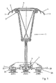
- FIG. 1 shows a current collector 1 for a railway vehicle not shown in detail.
- the current collector 1 serves for contacting a contact wire of a catenary.
- the pantograph 1 is a Einholm-pantograph, which discloses at its upper end a pantograph rocker 2 with one or more sanding strips 3 and one or more brackets 4, 5, which together form a bracket assembly 6.
- the brackets 4, 5 are arranged between the two grinding bars 3.
- the end portions of the bracket 4, 5 are referred to as Bügelauflauftechnik Anlagenner 7.
- FIG. 1 also lets us know where the pantograph rocker 2 is in the lowered position.
- the runners 7 and the contact strip 3 are partially shown in the vicinity of a base frame 9, which is attached as part of the current collector 1 on the vehicle.
- Position detectors 22, 23, 24, 25, which are symbolically associated with the ends of the Bügelauflauf Anlagenner 7 in the retracted and the extended position, serve to determine the respective position of the bracket 4, 5.
- the linkage of the current collector 1 in this embodiment comprises an upper arm with two bars, a handlebar and a forearm with a spar. In the present invention, it depends significantly on the configuration of the pantograph rocker 2.
- the following figures thus relate to current collector rockers, as for example in a in FIG. 1 illustrated pantograph 1 can be used.
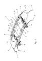
- FIG. 2 shows a pantograph rocker 2 in a perspective view.
- the pantograph rocker 2 is part of the in FIG. 1 illustrated pantograph.
- the pantograph rocker 2 comprises two grinding bars 3 arranged transversely to the direction of travel. Between the grinding bars 3 there is the bow arrangement 6 consisting of two straps 4, 5 displaceable in opposite directions.
- the grinding strips 3 each comprise a main grinding piece 3a and two opposite the main grinding piece 3a transversely displaceable to the direction of travel, pivotable additional grinding pieces 11 which are attached to the brackets 4, 5 and displaceable transversely to the direction of travel together with the brackets 4, 5.
- there are four displaceable supplementary grinding pieces 11 and two main grinding pieces 3a (FIG. Figures 2-6 ).
- the brackets 4, 5 are configured substantially Y-shaped, which is due to a so-called Bügelauflaufhorn 7.
- the Bügelauflaufhorn 7 extends between the two supplementary sanding pieces 11 on one side of the pantograph rocker 2 ( FIGS. 2 to 6 ).
- the entire arrangement is formed with respect to the central longitudinal axis of the pantograph rocker 2, ie in the direction of travel, mirror-symmetrical.
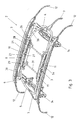
- the special geometry of the Bügelauflauf Anlagenner 7 is composed of different sections. Starting in the middle range results in the embodiment of FIG. 4 initially a broadening of the sanding strip 3 up to 1030 mm, because the additional grinding pieces 11 project laterally beyond the main grinding pieces 3a.
- the supplementary grinding pieces 11 each extend as far as a conductive region of the bracket 5.
- the ironing wheels 7 each have an insulated section 15 in their end regions (FIG. FIG. 7 ) extending over a projected length Li1 of min. 150 mm.
- the sanding strip 3 also has such an insulated section 13 (FIG. FIG. 7 ), but with a projected length of Li2 from 165 to 190 mm. The insulation is only provided on the outside.
- the Y-shaped configured Bügelauflaufhorn 7 is electrically conductive on the inside, so that an electrical contact between the two supplementary grinding pieces 11 on the respective Bügelauflaufhorn 7 is.
- the Bügelauflaufhorn 7 is executed by the Y-shape in an inner portion of two-legged and einschenkelig in an end section. This has the advantage that only the leg 15, which forms the end-side section, must be made electrically insulated, while the arcuate section 4, 5 of the Bügelauflaufhorns 7 conductive, that can not be carried out electrically isolated.
- a U-shaped Bügelauflaufhorn be provided with correspondingly insulated portions, and in this design, the Bügelauflaufhorn inside is electrically conductive to electrically connect the supplementary grinding pieces together.
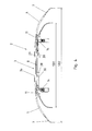
- FIG. 7 it is shown that the Bügelauflaufhorn 7 and the Schleifraunauflaufhorn 12 each have a measured over the horizontal Auflaufhornwinkel W1, W2.
- the Auflaufhornwinkel W1 of the Bügelauflaufhorns 7 is in this embodiment 40 °, while the Auflaufhornwinkel W2 of Schleiforgnauflaufhorns 12 is smaller. It is 30 ° in this embodiment.
- the straight portion 16 of the Bügelauflaufhorns 7 goes to its free end over a transition radius R1 to a vertically downwardly angled end 18 via.
- the transition radius R1 is 58 mm in this embodiment.
- the straight portion 17 of the Schleifraunauflaufhorns 12 also merges into a downwardly angled end 19, which is parallel to the other end 18 of the Bügelaufanks 7.
- the transition radius R2 in the transition from the straight section 17 to the end 19 is greater than the transition radius R1. In this embodiment, it is 140 mm.
- the straight sections 16, 17 are likewise connected via radii to the further longitudinal sections of the bow 5 or the sanding strip 3.
- the transition radius R3 in this embodiment is 260 °.
- the transition radius R4 of the grinding bar 3 of the main grinding piece 3a is smaller. It is 240 ° in this embodiment.
- transition angle W3 between the supplementary grinding pieces 11 and the adjoining Bügelauflaufhorn 7 can be seen.
- the transition angle W3 may preferably be ⁇ 15 °, in particular ⁇ 10 °.
- the transition angle W3 is 6 ° in this embodiment.
- the displacement of the bracket 4, 5 takes place in the horizontal direction, so that in the image plane of the FIG. 7 Supplementary grinding piece 11 shown completely recedes behind the main grinding piece 3. This also applies to the subsequent to the supplementary grinding piece 11 conductive portion which extends over the transition radius R3 in the straight portion 16.
- the isolated portion 13 of the Schleifraunauflaufhornes 12 extends approximately centrally into the straight portion 17 inside.
- the adjusting devices 8, 10 will be explained below, by means of which the brackets 4, 5 are displaced.
- the adjusting devices 8, 10 are identical. It is a lifting cylinder, with an extendable piston rod 20 ( FIG. 2 ). On the piston rod 20, an inner end 21 of the bracket 4, 5 is attached via a connecting element 26 ( FIG. 3 ).
- the connecting member 26 is disposed at an outer end of the supplementary grinding piece 11. It is transverse to the direction of movement of the bracket 4 in the horizontal direction, ie in the direction of the grinding bars 3, from the respective bracket 4, 5 from. Therefore, the piston rods 20 are laterally parallel to the brackets 4, 5 (FIG. FIG. 5 ).
- the immediately opposite ends 21 between the adjusting devices 8, 10 are arranged.
- the extended position FIG. 2
- the adjusting devices 8, 10 have an elongated housing 27 in the form of a cylinder ( FIG. 2 and 3 ).
- the housing 27 penetrates two respectively arranged in the end region of the housing 27 actuator holder 28, 29, which fix the housing 27 and thus the entire adjusting device 8, 10 stationary.
- FIG. 5 shows that the actuator holder 28, 29 are not connected to the grinding bars 3, but are connected via longitudinal struts 30, each with a Schleifraunhalter 14.
- the longitudinal struts 30 extend parallel to and below the piston rods 20.
- a positioner holder 28, 29 is connected to a longitudinal strut 30.
- each positioner holder 28, 29 is connected to a second positioner holder 28, 29 located in the same Arrangement adjacent to the second grinding bar 3 is located.
- the connection is made by transverse struts 31, which extend in the direction of travel.
- the actuator holders 28, 29 are configured U-shaped and open at the top. They have two legs, wherein in the upper free ends of each leg, the adjusting devices 8, 10 are mounted. In the lower region of the legs, the longitudinal struts 30 and cross struts 31 are attached.
- the brackets 4, 5 are supported exclusively by the piston rods 20. They do not come into contact with other supporting components in the retracted or extended position, so that they can not freeze.
- the length of the actuators 28, 29 is directly related to the width SB1 (B2 profile EN 50367) and the width SB2 (B3 profile EN 50367) of the pantograph rocker. 2
- FIG. 4 shows the possible widths SB1 and SB2.
- the total of four adjusting devices 8, 10 are connected directly to pneumatic or hydraulic lines.
- the control of the adjusting devices 8, 10, or the displacement between the positions with the widths SB1 and SB2 is controlled by a valve plate which is installed in the vehicle.
- the valve plate comprises valve elements for a logical AND connection of both adjusting devices 8, 10 of a Bügelauflaufhornes 7. If e.g. If one of the four actuating cylinders is not sufficiently supplied with compressed air, a pressure monitor gives an electrical error signal, so that a faulty adjustment is precluded.
- each of the two isolated portions 15 of the ironing horns 7 is monitored by a position detector. This is done for the rocker width SB1 by the position detectors 22, 23 and for the rocker width SB2 by the position detectors 24, 25 (FIG. Fig. 1 ).
- a position detector By combining a monitoring of the actuating cylinder by two pressure switches each Bügelauflaufhorn 7 with a single query of the position of each isolated portion 15 of the two Bügelauflauf Anlagenner 7 results in the necessary reliability. If an error message of the pressure monitor or the position detector 22, 23, 24, 25 detected, the lifting of the pantograph rocker 2 is not completed.
- the brackets 4, 5 are pneumatically or hydraulically lockable in the selected position by the actuators 21, i. preferably by adjusting cylinder, even.
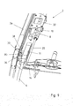
- FIGS. 8 and 9 show in perspective a part of a pantograph rocker 2 in retracted ( FIG. 8 ) and extended position ( FIG. 9 ).
- a support bearing 33 is provided to support the bracket 4 in the extended position.
- the support bearing 33 is fixed to the grinding bar holder 14 near the main grinding piece 3a.
- the support bearing 33 is formed as a bolt receptacle and serves to receive a bearing pin 34.
- the bearing pin 34 is fixed to the bracket 4 and is displaced together with the bracket 4 of the piston rod 20 of the adjusting device 8.
- the bearing pin 34 In the retracted position, the bearing pin 34 is adjacent to a positioner holder 32.
- the positioner holder 32 is formed from a U-shaped bent plate and accommodates two actuators 8, 10.
- the bearing pin 34 forms together with the support bearing 33 in the extended position of the bracket 4, a bearing assembly 35.
- the bearing pin 34 passes through the bolt holder completely and partially protrudes from the bolt holder.
- Both the bearing pin 34 and the support bearing 33 have contact surfaces 36, 37, at which touch the said components.
- the contact surfaces 36, 37 are made of a hydrophobic material.
- the bearing pin 34 is made of PTFE.
- the support bearing 33 consists of a water-repellent plastic.
- the bearing pin 34 is attached to a holder 38, wherein he a Drilled hole in the holder 38. He is on his side facing away from the support bearing 33 secured by a nut.
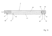
- FIG. 10 shows an adjusting device 8 for a current collector rocker 2 in longitudinal section, in which the Endlagenabfrage is integrated into the adjusting device 8.
- the adjusting device 8 is a double-acting, pneumatic piston-cylinder unit with a piston 39, within a cylinder 40.
- the piston 39 is connected to the piston rod 20.
- the cylinder 40 has four ports 41-44.
- the outer terminals 41, 44 serve to supply compressed air.
- a first and a second supply line 45, 46 are connected.
- the two middle connections 42, 43 are control connections for a first and a second control line 47, 48.
- a seal 49 on the piston 39 separates the adjacent first and second connections 41-44 from one another in the end positions of the piston 39.
- the connections 42, 43 for the control lines 47, 48 are arranged in the retracted or extended position near the seal 49.
- control lines 47, 48 are connected in a manner not shown with pressure switches, which conduct electrical signals to a likewise not shown electrical vehicle control, which logically links the signals.
- both control lines 47, 48 are pressurized.
- the second supply line 46 is pressurized.
- the pressure in the first supply line 45 is lowered at the same time. He then falls initially in the two control lines 47, 48 from.
- the pressure in the second control line 48 rises again.
- the pressure in the first control line 47 also increases.
- the second supply line 46 may be connected to a channel of a supplementary grinding piece 11 for monitoring the supplementary grinding piece 11 (ADD query).
Landscapes
- Engineering & Computer Science (AREA)
- Power Engineering (AREA)
- Transportation (AREA)
- Mechanical Engineering (AREA)
- Current-Collector Devices For Electrically Propelled Vehicles (AREA)
Priority Applications (1)
| Application Number | Priority Date | Filing Date | Title |
|---|---|---|---|
| PL13183805T PL2705971T3 (pl) | 2012-09-11 | 2013-09-10 | Odbierak prądu |
Applications Claiming Priority (1)
| Application Number | Priority Date | Filing Date | Title |
|---|---|---|---|
| DE102012108491.2A DE102012108491A1 (de) | 2012-09-11 | 2012-09-11 | Stromabnehmer |
Publications (3)
| Publication Number | Publication Date |
|---|---|
| EP2705971A2 true EP2705971A2 (fr) | 2014-03-12 |
| EP2705971A3 EP2705971A3 (fr) | 2015-01-21 |
| EP2705971B1 EP2705971B1 (fr) | 2015-11-04 |
Family
ID=49123761
Family Applications (1)
| Application Number | Title | Priority Date | Filing Date |
|---|---|---|---|
| EP13183805.4A Active EP2705971B1 (fr) | 2012-09-11 | 2013-09-10 | Prise de courant |
Country Status (4)
| Country | Link |
|---|---|
| EP (1) | EP2705971B1 (fr) |
| DE (1) | DE102012108491A1 (fr) |
| ES (1) | ES2557814T3 (fr) |
| PL (1) | PL2705971T3 (fr) |
Cited By (2)
| Publication number | Priority date | Publication date | Assignee | Title |
|---|---|---|---|---|
| CN113022316A (zh) * | 2021-04-08 | 2021-06-25 | 中国铁建电气化局集团北方工程有限公司 | 一种地铁刚性接触网同相供电装置及其供电方法 |
| WO2022078038A1 (fr) * | 2020-10-15 | 2022-04-21 | 中车大同电力机车有限公司 | Tête de pantographe, pantographe et procédé de commande de pantographe |
Families Citing this family (3)
| Publication number | Priority date | Publication date | Assignee | Title |
|---|---|---|---|---|
| CN106515460B (zh) * | 2016-09-27 | 2023-12-15 | 宇通客车股份有限公司 | 一种受电弓充电系统、受电弓防护罩及车辆 |
| AT523852B1 (de) * | 2020-05-19 | 2022-05-15 | Siemens Mobility Austria Gmbh | Wippe für einen Stromabnehmer eines Fahrzeugs |
| DE102021107676A1 (de) * | 2021-03-26 | 2022-09-29 | Stemmann-Technik Gmbh | Stromabnehmer |
Citations (3)
| Publication number | Priority date | Publication date | Assignee | Title |
|---|---|---|---|---|
| DE9304251U1 (de) | 1993-03-25 | 1993-07-22 | Schunk Bahntechnik Ges.m.b.H., Salzburg | Stromabnehmer |
| DE19914566A1 (de) | 1999-03-31 | 2000-10-05 | Abb Daimler Benz Transp | Stromabnehmersystem |
| EP2455251A2 (fr) | 2010-11-23 | 2012-05-23 | Richard AG, Murgenthal | Archet de pantographe |
Family Cites Families (3)
| Publication number | Priority date | Publication date | Assignee | Title |
|---|---|---|---|---|
| DE29601731U1 (de) * | 1995-06-01 | 1996-04-18 | Siemens AG, 80333 München | Stromabnehmer |
| DE19601009C1 (de) * | 1996-01-15 | 1997-06-05 | Schunk Bahntechnik Ges M B H | Stromabnehmer |
| DE102011013267A1 (de) * | 2011-03-07 | 2012-09-13 | Bombardier Transportation Gmbh | Stromabnehmer |
-
2012
- 2012-09-11 DE DE102012108491.2A patent/DE102012108491A1/de not_active Withdrawn
-
2013
- 2013-09-10 EP EP13183805.4A patent/EP2705971B1/fr active Active
- 2013-09-10 ES ES13183805.4T patent/ES2557814T3/es active Active
- 2013-09-10 PL PL13183805T patent/PL2705971T3/pl unknown
Patent Citations (3)
| Publication number | Priority date | Publication date | Assignee | Title |
|---|---|---|---|---|
| DE9304251U1 (de) | 1993-03-25 | 1993-07-22 | Schunk Bahntechnik Ges.m.b.H., Salzburg | Stromabnehmer |
| DE19914566A1 (de) | 1999-03-31 | 2000-10-05 | Abb Daimler Benz Transp | Stromabnehmersystem |
| EP2455251A2 (fr) | 2010-11-23 | 2012-05-23 | Richard AG, Murgenthal | Archet de pantographe |
Cited By (3)
| Publication number | Priority date | Publication date | Assignee | Title |
|---|---|---|---|---|
| WO2022078038A1 (fr) * | 2020-10-15 | 2022-04-21 | 中车大同电力机车有限公司 | Tête de pantographe, pantographe et procédé de commande de pantographe |
| CN113022316A (zh) * | 2021-04-08 | 2021-06-25 | 中国铁建电气化局集团北方工程有限公司 | 一种地铁刚性接触网同相供电装置及其供电方法 |
| CN113022316B (zh) * | 2021-04-08 | 2022-06-24 | 中国铁建电气化局集团北方工程有限公司 | 一种地铁刚性接触网同相供电装置及其供电方法 |
Also Published As
| Publication number | Publication date |
|---|---|
| EP2705971A3 (fr) | 2015-01-21 |
| DE102012108491A1 (de) | 2014-06-18 |
| ES2557814T3 (es) | 2016-01-28 |
| PL2705971T3 (pl) | 2016-02-29 |
| EP2705971B1 (fr) | 2015-11-04 |
Similar Documents
| Publication | Publication Date | Title |
|---|---|---|
| EP2705971B1 (fr) | Prise de courant | |
| AT520873B1 (de) | Lateraler Stromabnehmer und Elektrofahrzeug | |
| DE102008047249A1 (de) | Rückenlehnenstruktur für einen Kraftfahrzeugsitz | |
| DE102016113253B4 (de) | Fahrzeug mit einer im Bedarfsfall ausbildbaren Strömungsabrisskante | |
| EP0785167B1 (fr) | Equipement de translation latérale pour fourches de chariots élévateurs | |
| DE202012002833U1 (de) | Fahrzeuglift | |
| DE202012002832U1 (de) | Fahrzeuglift mit Vorspanneinrichtung | |
| DE2711994B2 (de) | Fahrzeug, das gegenüber einem Fahrweg mit Hilfe einer anziehenden magnetischen Einrichtung und einer Zusatzkrafteinrichtung gehalten wird | |
| EP2346710B1 (fr) | Collecteur de courant pour véhicule ferroviaire | |
| DE102012108492A1 (de) | Stromabnehmer | |
| DE2231980B2 (de) | Von einem linearmotor angetriebenes schienenfahrzeug | |
| DE202015100777U1 (de) | Achsaufhängung | |
| EP2497674B1 (fr) | Prise de courant | |
| DE102015012757B4 (de) | Schienenführungseinrichtung für Zweiwegefahrzeuge | |
| DE10028948A1 (de) | Stromabnehmer für elektrisch betriebene Schienenfahrzeuge | |
| EP2641576B1 (fr) | Plate-forme élévatrice de véhicule | |
| EP2488384B1 (fr) | Prise de courant | |
| EP0281880B1 (fr) | Zone de coeur de voie d'aiguillages ou de croisements | |
| EP0386344B1 (fr) | Coulisseau de levage | |
| DE202011004799U1 (de) | Instandhaltungsfahrzeug | |
| DE102005044428B4 (de) | Vorrichtung zum Schneiden eines Stranges aus plastisch verformbarem Material, insbesondere Ton, mit einem durch wenigstens ein Antriebselement bewegbaren Halter für wenigstens einen Schneidedraht | |
| EP2784222A1 (fr) | Dispositif de glissière de sécurité, notamment système de transfert de glissière de sécurité, avec unité de verrouillage et abaissement court | |
| DE102017124569B4 (de) | Spoilervorrichtung für einen Frontabschnitt eines Fahrzeugs | |
| EP3566895A1 (fr) | Prise de courant pour un véhicule sur rail | |
| DE102005011618A1 (de) | Stromabnehmer für ein Fahrzeug, insbesondere ein Eisenbahn- oder ein Straßenbahnfahrzeug |
Legal Events
| Date | Code | Title | Description |
|---|---|---|---|
| PUAI | Public reference made under article 153(3) epc to a published international application that has entered the european phase |
Free format text: ORIGINAL CODE: 0009012 |
|
| AK | Designated contracting states |
Kind code of ref document: A2 Designated state(s): AL AT BE BG CH CY CZ DE DK EE ES FI FR GB GR HR HU IE IS IT LI LT LU LV MC MK MT NL NO PL PT RO RS SE SI SK SM TR |
|
| AX | Request for extension of the european patent |
Extension state: BA ME |
|
| PUAL | Search report despatched |
Free format text: ORIGINAL CODE: 0009013 |
|
| AK | Designated contracting states |
Kind code of ref document: A3 Designated state(s): AL AT BE BG CH CY CZ DE DK EE ES FI FR GB GR HR HU IE IS IT LI LT LU LV MC MK MT NL NO PL PT RO RS SE SI SK SM TR |
|
| AX | Request for extension of the european patent |
Extension state: BA ME |
|
| RIC1 | Information provided on ipc code assigned before grant |
Ipc: B60L 5/19 20060101AFI20141217BHEP |
|
| 17P | Request for examination filed |
Effective date: 20150123 |
|
| GRAP | Despatch of communication of intention to grant a patent |
Free format text: ORIGINAL CODE: EPIDOSNIGR1 |
|
| INTG | Intention to grant announced |
Effective date: 20150615 |
|
| GRAS | Grant fee paid |
Free format text: ORIGINAL CODE: EPIDOSNIGR3 |
|
| GRAA | (expected) grant |
Free format text: ORIGINAL CODE: 0009210 |
|
| AK | Designated contracting states |
Kind code of ref document: B1 Designated state(s): AL AT BE BG CH CY CZ DE DK EE ES FI FR GB GR HR HU IE IS IT LI LT LU LV MC MK MT NL NO PL PT RO RS SE SI SK SM TR |
|
| REG | Reference to a national code |
Ref country code: GB Ref legal event code: FG4D Free format text: NOT ENGLISH |
|
| REG | Reference to a national code |
Ref country code: CH Ref legal event code: EP |
|
| REG | Reference to a national code |
Ref country code: AT Ref legal event code: REF Ref document number: 758936 Country of ref document: AT Kind code of ref document: T Effective date: 20151115 |
|
| REG | Reference to a national code |
Ref country code: IE Ref legal event code: FG4D Free format text: LANGUAGE OF EP DOCUMENT: GERMAN |
|
| REG | Reference to a national code |
Ref country code: DE Ref legal event code: R096 Ref document number: 502013001444 Country of ref document: DE |
|
| REG | Reference to a national code |
Ref country code: SE Ref legal event code: TRGR |
|
| REG | Reference to a national code |
Ref country code: ES Ref legal event code: FG2A Ref document number: 2557814 Country of ref document: ES Kind code of ref document: T3 Effective date: 20160128 |
|
| REG | Reference to a national code |
Ref country code: NL Ref legal event code: MP Effective date: 20151104 |
|
| REG | Reference to a national code |
Ref country code: LT Ref legal event code: MG4D |
|
| PG25 | Lapsed in a contracting state [announced via postgrant information from national office to epo] |
Ref country code: NO Free format text: LAPSE BECAUSE OF FAILURE TO SUBMIT A TRANSLATION OF THE DESCRIPTION OR TO PAY THE FEE WITHIN THE PRESCRIBED TIME-LIMIT Effective date: 20160204 Ref country code: LT Free format text: LAPSE BECAUSE OF FAILURE TO SUBMIT A TRANSLATION OF THE DESCRIPTION OR TO PAY THE FEE WITHIN THE PRESCRIBED TIME-LIMIT Effective date: 20151104 Ref country code: IS Free format text: LAPSE BECAUSE OF FAILURE TO SUBMIT A TRANSLATION OF THE DESCRIPTION OR TO PAY THE FEE WITHIN THE PRESCRIBED TIME-LIMIT Effective date: 20160304 Ref country code: NL Free format text: LAPSE BECAUSE OF FAILURE TO SUBMIT A TRANSLATION OF THE DESCRIPTION OR TO PAY THE FEE WITHIN THE PRESCRIBED TIME-LIMIT Effective date: 20151104 Ref country code: HR Free format text: LAPSE BECAUSE OF FAILURE TO SUBMIT A TRANSLATION OF THE DESCRIPTION OR TO PAY THE FEE WITHIN THE PRESCRIBED TIME-LIMIT Effective date: 20151104 |
|
| PG25 | Lapsed in a contracting state [announced via postgrant information from national office to epo] |
Ref country code: FI Free format text: LAPSE BECAUSE OF FAILURE TO SUBMIT A TRANSLATION OF THE DESCRIPTION OR TO PAY THE FEE WITHIN THE PRESCRIBED TIME-LIMIT Effective date: 20151104 Ref country code: RS Free format text: LAPSE BECAUSE OF FAILURE TO SUBMIT A TRANSLATION OF THE DESCRIPTION OR TO PAY THE FEE WITHIN THE PRESCRIBED TIME-LIMIT Effective date: 20151104 Ref country code: GR Free format text: LAPSE BECAUSE OF FAILURE TO SUBMIT A TRANSLATION OF THE DESCRIPTION OR TO PAY THE FEE WITHIN THE PRESCRIBED TIME-LIMIT Effective date: 20160205 Ref country code: PT Free format text: LAPSE BECAUSE OF FAILURE TO SUBMIT A TRANSLATION OF THE DESCRIPTION OR TO PAY THE FEE WITHIN THE PRESCRIBED TIME-LIMIT Effective date: 20160304 Ref country code: LV Free format text: LAPSE BECAUSE OF FAILURE TO SUBMIT A TRANSLATION OF THE DESCRIPTION OR TO PAY THE FEE WITHIN THE PRESCRIBED TIME-LIMIT Effective date: 20151104 |
|
| REG | Reference to a national code |
Ref country code: DE Ref legal event code: R097 Ref document number: 502013001444 Country of ref document: DE |
|
| PG25 | Lapsed in a contracting state [announced via postgrant information from national office to epo] |
Ref country code: EE Free format text: LAPSE BECAUSE OF FAILURE TO SUBMIT A TRANSLATION OF THE DESCRIPTION OR TO PAY THE FEE WITHIN THE PRESCRIBED TIME-LIMIT Effective date: 20151104 Ref country code: RO Free format text: LAPSE BECAUSE OF FAILURE TO SUBMIT A TRANSLATION OF THE DESCRIPTION OR TO PAY THE FEE WITHIN THE PRESCRIBED TIME-LIMIT Effective date: 20151104 Ref country code: SK Free format text: LAPSE BECAUSE OF FAILURE TO SUBMIT A TRANSLATION OF THE DESCRIPTION OR TO PAY THE FEE WITHIN THE PRESCRIBED TIME-LIMIT Effective date: 20151104 Ref country code: SM Free format text: LAPSE BECAUSE OF FAILURE TO SUBMIT A TRANSLATION OF THE DESCRIPTION OR TO PAY THE FEE WITHIN THE PRESCRIBED TIME-LIMIT Effective date: 20151104 Ref country code: DK Free format text: LAPSE BECAUSE OF FAILURE TO SUBMIT A TRANSLATION OF THE DESCRIPTION OR TO PAY THE FEE WITHIN THE PRESCRIBED TIME-LIMIT Effective date: 20151104 |
|
| PLBE | No opposition filed within time limit |
Free format text: ORIGINAL CODE: 0009261 |
|
| STAA | Information on the status of an ep patent application or granted ep patent |
Free format text: STATUS: NO OPPOSITION FILED WITHIN TIME LIMIT |
|
| REG | Reference to a national code |
Ref country code: FR Ref legal event code: PLFP Year of fee payment: 4 |
|
| 26N | No opposition filed |
Effective date: 20160805 |
|
| PG25 | Lapsed in a contracting state [announced via postgrant information from national office to epo] |
Ref country code: SI Free format text: LAPSE BECAUSE OF FAILURE TO SUBMIT A TRANSLATION OF THE DESCRIPTION OR TO PAY THE FEE WITHIN THE PRESCRIBED TIME-LIMIT Effective date: 20151104 |
|
| PG25 | Lapsed in a contracting state [announced via postgrant information from national office to epo] |
Ref country code: BE Free format text: LAPSE BECAUSE OF NON-PAYMENT OF DUE FEES Effective date: 20160930 |
|
| PG25 | Lapsed in a contracting state [announced via postgrant information from national office to epo] |
Ref country code: MC Free format text: LAPSE BECAUSE OF FAILURE TO SUBMIT A TRANSLATION OF THE DESCRIPTION OR TO PAY THE FEE WITHIN THE PRESCRIBED TIME-LIMIT Effective date: 20151104 |
|
| REG | Reference to a national code |
Ref country code: IE Ref legal event code: MM4A |
|
| PG25 | Lapsed in a contracting state [announced via postgrant information from national office to epo] |
Ref country code: IE Free format text: LAPSE BECAUSE OF NON-PAYMENT OF DUE FEES Effective date: 20160910 |
|
| PG25 | Lapsed in a contracting state [announced via postgrant information from national office to epo] |
Ref country code: LU Free format text: LAPSE BECAUSE OF NON-PAYMENT OF DUE FEES Effective date: 20160910 |
|
| REG | Reference to a national code |
Ref country code: FR Ref legal event code: PLFP Year of fee payment: 5 |
|
| REG | Reference to a national code |
Ref country code: BE Ref legal event code: MM Effective date: 20160930 |
|
| GBPC | Gb: european patent ceased through non-payment of renewal fee |
Effective date: 20170910 |
|
| PG25 | Lapsed in a contracting state [announced via postgrant information from national office to epo] |
Ref country code: HU Free format text: LAPSE BECAUSE OF FAILURE TO SUBMIT A TRANSLATION OF THE DESCRIPTION OR TO PAY THE FEE WITHIN THE PRESCRIBED TIME-LIMIT; INVALID AB INITIO Effective date: 20130910 Ref country code: CY Free format text: LAPSE BECAUSE OF FAILURE TO SUBMIT A TRANSLATION OF THE DESCRIPTION OR TO PAY THE FEE WITHIN THE PRESCRIBED TIME-LIMIT Effective date: 20151104 |
|
| PG25 | Lapsed in a contracting state [announced via postgrant information from national office to epo] |
Ref country code: MK Free format text: LAPSE BECAUSE OF FAILURE TO SUBMIT A TRANSLATION OF THE DESCRIPTION OR TO PAY THE FEE WITHIN THE PRESCRIBED TIME-LIMIT Effective date: 20151104 Ref country code: MT Free format text: LAPSE BECAUSE OF FAILURE TO SUBMIT A TRANSLATION OF THE DESCRIPTION OR TO PAY THE FEE WITHIN THE PRESCRIBED TIME-LIMIT Effective date: 20151104 |
|
| PG25 | Lapsed in a contracting state [announced via postgrant information from national office to epo] |
Ref country code: GB Free format text: LAPSE BECAUSE OF NON-PAYMENT OF DUE FEES Effective date: 20170910 Ref country code: BG Free format text: LAPSE BECAUSE OF FAILURE TO SUBMIT A TRANSLATION OF THE DESCRIPTION OR TO PAY THE FEE WITHIN THE PRESCRIBED TIME-LIMIT Effective date: 20151104 |
|
| REG | Reference to a national code |
Ref country code: FR Ref legal event code: PLFP Year of fee payment: 6 |
|
| PG25 | Lapsed in a contracting state [announced via postgrant information from national office to epo] |
Ref country code: TR Free format text: LAPSE BECAUSE OF FAILURE TO SUBMIT A TRANSLATION OF THE DESCRIPTION OR TO PAY THE FEE WITHIN THE PRESCRIBED TIME-LIMIT Effective date: 20151104 Ref country code: AL Free format text: LAPSE BECAUSE OF FAILURE TO SUBMIT A TRANSLATION OF THE DESCRIPTION OR TO PAY THE FEE WITHIN THE PRESCRIBED TIME-LIMIT Effective date: 20151104 |
|
| PGFP | Annual fee paid to national office [announced via postgrant information from national office to epo] |
Ref country code: FR Payment date: 20200914 Year of fee payment: 8 Ref country code: CZ Payment date: 20200910 Year of fee payment: 8 |
|
| PGFP | Annual fee paid to national office [announced via postgrant information from national office to epo] |
Ref country code: PL Payment date: 20200902 Year of fee payment: 8 Ref country code: IT Payment date: 20200922 Year of fee payment: 8 Ref country code: SE Payment date: 20200925 Year of fee payment: 8 |
|
| PGFP | Annual fee paid to national office [announced via postgrant information from national office to epo] |
Ref country code: ES Payment date: 20201120 Year of fee payment: 8 |
|
| REG | Reference to a national code |
Ref country code: SE Ref legal event code: EUG |
|
| PG25 | Lapsed in a contracting state [announced via postgrant information from national office to epo] |
Ref country code: CZ Free format text: LAPSE BECAUSE OF NON-PAYMENT OF DUE FEES Effective date: 20210910 |
|
| PG25 | Lapsed in a contracting state [announced via postgrant information from national office to epo] |
Ref country code: SE Free format text: LAPSE BECAUSE OF NON-PAYMENT OF DUE FEES Effective date: 20210911 Ref country code: FR Free format text: LAPSE BECAUSE OF NON-PAYMENT OF DUE FEES Effective date: 20210930 |
|
| PG25 | Lapsed in a contracting state [announced via postgrant information from national office to epo] |
Ref country code: IT Free format text: LAPSE BECAUSE OF NON-PAYMENT OF DUE FEES Effective date: 20210910 |
|
| REG | Reference to a national code |
Ref country code: ES Ref legal event code: FD2A Effective date: 20221107 |
|
| PG25 | Lapsed in a contracting state [announced via postgrant information from national office to epo] |
Ref country code: ES Free format text: LAPSE BECAUSE OF NON-PAYMENT OF DUE FEES Effective date: 20210911 |
|
| PG25 | Lapsed in a contracting state [announced via postgrant information from national office to epo] |
Ref country code: PL Free format text: LAPSE BECAUSE OF NON-PAYMENT OF DUE FEES Effective date: 20210910 |
|
| P01 | Opt-out of the competence of the unified patent court (upc) registered |
Effective date: 20230822 |
|
| REG | Reference to a national code |
Ref country code: DE Ref legal event code: R082 Ref document number: 502013001444 Country of ref document: DE Representative=s name: PATENTANWAELTE BRESSEL UND PARTNER MBB, DE |
|
| REG | Reference to a national code |
Ref country code: CH Ref legal event code: U11 Free format text: ST27 STATUS EVENT CODE: U-0-0-U10-U11 (AS PROVIDED BY THE NATIONAL OFFICE) Effective date: 20251001 |
|
| PGFP | Annual fee paid to national office [announced via postgrant information from national office to epo] |
Ref country code: DE Payment date: 20250919 Year of fee payment: 13 |
|
| PGFP | Annual fee paid to national office [announced via postgrant information from national office to epo] |
Ref country code: AT Payment date: 20250919 Year of fee payment: 13 |
|
| PGFP | Annual fee paid to national office [announced via postgrant information from national office to epo] |
Ref country code: CH Payment date: 20251001 Year of fee payment: 13 |