EP2705973B1 - Elektrofahrzeug mit Spreizsitz, Stromversorgung und Verfahren zu deren Steuerung - Google Patents
Elektrofahrzeug mit Spreizsitz, Stromversorgung und Verfahren zu deren Steuerung Download PDFInfo
- Publication number
- EP2705973B1 EP2705973B1 EP13181387.5A EP13181387A EP2705973B1 EP 2705973 B1 EP2705973 B1 EP 2705973B1 EP 13181387 A EP13181387 A EP 13181387A EP 2705973 B1 EP2705973 B1 EP 2705973B1
- Authority
- EP
- European Patent Office
- Prior art keywords
- motor
- electric
- target
- wheel
- power
- Prior art date
- Legal status (The legal status is an assumption and is not a legal conclusion. Google has not performed a legal analysis and makes no representation as to the accuracy of the status listed.)
- Active
Links
Images




Classifications
-
- B—PERFORMING OPERATIONS; TRANSPORTING
- B60—VEHICLES IN GENERAL
- B60L—PROPULSION OF ELECTRICALLY-PROPELLED VEHICLES; SUPPLYING ELECTRIC POWER FOR AUXILIARY EQUIPMENT OF ELECTRICALLY-PROPELLED VEHICLES; ELECTRODYNAMIC BRAKE SYSTEMS FOR VEHICLES IN GENERAL; MAGNETIC SUSPENSION OR LEVITATION FOR VEHICLES; MONITORING OPERATING VARIABLES OF ELECTRICALLY-PROPELLED VEHICLES; ELECTRIC SAFETY DEVICES FOR ELECTRICALLY-PROPELLED VEHICLES
- B60L15/00—Methods, circuits, or devices for controlling the traction-motor speed of electrically-propelled vehicles
- B60L15/20—Methods, circuits, or devices for controlling the traction-motor speed of electrically-propelled vehicles for control of the vehicle or its driving motor to achieve a desired performance, e.g. speed, torque, programmed variation of speed
- B60L15/2054—Methods, circuits, or devices for controlling the traction-motor speed of electrically-propelled vehicles for control of the vehicle or its driving motor to achieve a desired performance, e.g. speed, torque, programmed variation of speed by controlling transmissions or clutches
-
- B—PERFORMING OPERATIONS; TRANSPORTING
- B60—VEHICLES IN GENERAL
- B60L—PROPULSION OF ELECTRICALLY-PROPELLED VEHICLES; SUPPLYING ELECTRIC POWER FOR AUXILIARY EQUIPMENT OF ELECTRICALLY-PROPELLED VEHICLES; ELECTRODYNAMIC BRAKE SYSTEMS FOR VEHICLES IN GENERAL; MAGNETIC SUSPENSION OR LEVITATION FOR VEHICLES; MONITORING OPERATING VARIABLES OF ELECTRICALLY-PROPELLED VEHICLES; ELECTRIC SAFETY DEVICES FOR ELECTRICALLY-PROPELLED VEHICLES
- B60L15/00—Methods, circuits, or devices for controlling the traction-motor speed of electrically-propelled vehicles
- B60L15/20—Methods, circuits, or devices for controlling the traction-motor speed of electrically-propelled vehicles for control of the vehicle or its driving motor to achieve a desired performance, e.g. speed, torque, programmed variation of speed
-
- B—PERFORMING OPERATIONS; TRANSPORTING
- B60—VEHICLES IN GENERAL
- B60L—PROPULSION OF ELECTRICALLY-PROPELLED VEHICLES; SUPPLYING ELECTRIC POWER FOR AUXILIARY EQUIPMENT OF ELECTRICALLY-PROPELLED VEHICLES; ELECTRODYNAMIC BRAKE SYSTEMS FOR VEHICLES IN GENERAL; MAGNETIC SUSPENSION OR LEVITATION FOR VEHICLES; MONITORING OPERATING VARIABLES OF ELECTRICALLY-PROPELLED VEHICLES; ELECTRIC SAFETY DEVICES FOR ELECTRICALLY-PROPELLED VEHICLES
- B60L50/00—Electric propulsion with power supplied within the vehicle
- B60L50/20—Electric propulsion with power supplied within the vehicle using propulsion power generated by humans or animals
-
- B—PERFORMING OPERATIONS; TRANSPORTING
- B62—LAND VEHICLES FOR TRAVELLING OTHERWISE THAN ON RAILS
- B62M—RIDER PROPULSION OF WHEELED VEHICLES OR SLEDGES; POWERED PROPULSION OF SLEDGES OR SINGLE-TRACK CYCLES; TRANSMISSIONS SPECIALLY ADAPTED FOR SUCH VEHICLES
- B62M6/00—Rider propulsion of wheeled vehicles with additional source of power, e.g. combustion engine or electric motor
- B62M6/40—Rider propelled cycles with auxiliary electric motor
- B62M6/45—Control or actuating devices therefor
-
- B—PERFORMING OPERATIONS; TRANSPORTING
- B62—LAND VEHICLES FOR TRAVELLING OTHERWISE THAN ON RAILS
- B62M—RIDER PROPULSION OF WHEELED VEHICLES OR SLEDGES; POWERED PROPULSION OF SLEDGES OR SINGLE-TRACK CYCLES; TRANSMISSIONS SPECIALLY ADAPTED FOR SUCH VEHICLES
- B62M6/00—Rider propulsion of wheeled vehicles with additional source of power, e.g. combustion engine or electric motor
- B62M6/40—Rider propelled cycles with auxiliary electric motor
- B62M6/55—Rider propelled cycles with auxiliary electric motor power-driven at crank shafts parts
-
- B—PERFORMING OPERATIONS; TRANSPORTING
- B60—VEHICLES IN GENERAL
- B60L—PROPULSION OF ELECTRICALLY-PROPELLED VEHICLES; SUPPLYING ELECTRIC POWER FOR AUXILIARY EQUIPMENT OF ELECTRICALLY-PROPELLED VEHICLES; ELECTRODYNAMIC BRAKE SYSTEMS FOR VEHICLES IN GENERAL; MAGNETIC SUSPENSION OR LEVITATION FOR VEHICLES; MONITORING OPERATING VARIABLES OF ELECTRICALLY-PROPELLED VEHICLES; ELECTRIC SAFETY DEVICES FOR ELECTRICALLY-PROPELLED VEHICLES
- B60L2200/00—Type of vehicles
- B60L2200/12—Bikes
-
- B—PERFORMING OPERATIONS; TRANSPORTING
- B60—VEHICLES IN GENERAL
- B60L—PROPULSION OF ELECTRICALLY-PROPELLED VEHICLES; SUPPLYING ELECTRIC POWER FOR AUXILIARY EQUIPMENT OF ELECTRICALLY-PROPELLED VEHICLES; ELECTRODYNAMIC BRAKE SYSTEMS FOR VEHICLES IN GENERAL; MAGNETIC SUSPENSION OR LEVITATION FOR VEHICLES; MONITORING OPERATING VARIABLES OF ELECTRICALLY-PROPELLED VEHICLES; ELECTRIC SAFETY DEVICES FOR ELECTRICALLY-PROPELLED VEHICLES
- B60L2200/00—Type of vehicles
- B60L2200/46—Vehicles with auxiliary ad-on propulsions, e.g. add-on electric motor kits for bicycles
-
- B—PERFORMING OPERATIONS; TRANSPORTING
- B60—VEHICLES IN GENERAL
- B60L—PROPULSION OF ELECTRICALLY-PROPELLED VEHICLES; SUPPLYING ELECTRIC POWER FOR AUXILIARY EQUIPMENT OF ELECTRICALLY-PROPELLED VEHICLES; ELECTRODYNAMIC BRAKE SYSTEMS FOR VEHICLES IN GENERAL; MAGNETIC SUSPENSION OR LEVITATION FOR VEHICLES; MONITORING OPERATING VARIABLES OF ELECTRICALLY-PROPELLED VEHICLES; ELECTRIC SAFETY DEVICES FOR ELECTRICALLY-PROPELLED VEHICLES
- B60L2240/00—Control parameters of input or output; Target parameters
- B60L2240/10—Vehicle control parameters
- B60L2240/14—Acceleration
- B60L2240/20—Acceleration angular
-
- B—PERFORMING OPERATIONS; TRANSPORTING
- B60—VEHICLES IN GENERAL
- B60L—PROPULSION OF ELECTRICALLY-PROPELLED VEHICLES; SUPPLYING ELECTRIC POWER FOR AUXILIARY EQUIPMENT OF ELECTRICALLY-PROPELLED VEHICLES; ELECTRODYNAMIC BRAKE SYSTEMS FOR VEHICLES IN GENERAL; MAGNETIC SUSPENSION OR LEVITATION FOR VEHICLES; MONITORING OPERATING VARIABLES OF ELECTRICALLY-PROPELLED VEHICLES; ELECTRIC SAFETY DEVICES FOR ELECTRICALLY-PROPELLED VEHICLES
- B60L2240/00—Control parameters of input or output; Target parameters
- B60L2240/40—Drive Train control parameters
- B60L2240/42—Drive Train control parameters related to electric machines
- B60L2240/423—Torque
-
- B—PERFORMING OPERATIONS; TRANSPORTING
- B60—VEHICLES IN GENERAL
- B60L—PROPULSION OF ELECTRICALLY-PROPELLED VEHICLES; SUPPLYING ELECTRIC POWER FOR AUXILIARY EQUIPMENT OF ELECTRICALLY-PROPELLED VEHICLES; ELECTRODYNAMIC BRAKE SYSTEMS FOR VEHICLES IN GENERAL; MAGNETIC SUSPENSION OR LEVITATION FOR VEHICLES; MONITORING OPERATING VARIABLES OF ELECTRICALLY-PROPELLED VEHICLES; ELECTRIC SAFETY DEVICES FOR ELECTRICALLY-PROPELLED VEHICLES
- B60L2260/00—Operating Modes
- B60L2260/20—Drive modes; Transition between modes
- B60L2260/22—Standstill, e.g. zero speed
-
- B—PERFORMING OPERATIONS; TRANSPORTING
- B60—VEHICLES IN GENERAL
- B60L—PROPULSION OF ELECTRICALLY-PROPELLED VEHICLES; SUPPLYING ELECTRIC POWER FOR AUXILIARY EQUIPMENT OF ELECTRICALLY-PROPELLED VEHICLES; ELECTRODYNAMIC BRAKE SYSTEMS FOR VEHICLES IN GENERAL; MAGNETIC SUSPENSION OR LEVITATION FOR VEHICLES; MONITORING OPERATING VARIABLES OF ELECTRICALLY-PROPELLED VEHICLES; ELECTRIC SAFETY DEVICES FOR ELECTRICALLY-PROPELLED VEHICLES
- B60L2260/00—Operating Modes
- B60L2260/20—Drive modes; Transition between modes
- B60L2260/26—Transition between different drive modes
-
- Y—GENERAL TAGGING OF NEW TECHNOLOGICAL DEVELOPMENTS; GENERAL TAGGING OF CROSS-SECTIONAL TECHNOLOGIES SPANNING OVER SEVERAL SECTIONS OF THE IPC; TECHNICAL SUBJECTS COVERED BY FORMER USPC CROSS-REFERENCE ART COLLECTIONS [XRACs] AND DIGESTS
- Y02—TECHNOLOGIES OR APPLICATIONS FOR MITIGATION OR ADAPTATION AGAINST CLIMATE CHANGE
- Y02T—CLIMATE CHANGE MITIGATION TECHNOLOGIES RELATED TO TRANSPORTATION
- Y02T10/00—Road transport of goods or passengers
- Y02T10/60—Other road transportation technologies with climate change mitigation effect
- Y02T10/64—Electric machine technologies in electromobility
-
- Y—GENERAL TAGGING OF NEW TECHNOLOGICAL DEVELOPMENTS; GENERAL TAGGING OF CROSS-SECTIONAL TECHNOLOGIES SPANNING OVER SEVERAL SECTIONS OF THE IPC; TECHNICAL SUBJECTS COVERED BY FORMER USPC CROSS-REFERENCE ART COLLECTIONS [XRACs] AND DIGESTS
- Y02—TECHNOLOGIES OR APPLICATIONS FOR MITIGATION OR ADAPTATION AGAINST CLIMATE CHANGE
- Y02T—CLIMATE CHANGE MITIGATION TECHNOLOGIES RELATED TO TRANSPORTATION
- Y02T10/00—Road transport of goods or passengers
- Y02T10/60—Other road transportation technologies with climate change mitigation effect
- Y02T10/72—Electric energy management in electromobility
Definitions
- the present invention relates to an electric vehicle.
- An electric vehicle for example an electric power-assisted bicycle in which driving force of an electric motor is transmitted to a wheel via a transmission is known(refer to Japanese Patent Publication JP-A-11-59557 ).
- the electric power-assisted bicycle controls current applied to the electric motor in response to pedal stepping force that is input into a pedal pressed down by a rider.
- the behavior of the vehicle is varied in response to the gear ratio selected in the transmission, even if the pedal is stepped at the same stepping force and the electric current of the same magnitude is applied to the electric motor.
- the transmission gear with the small transmission gear ratio is selected, a rider feels that a vehicle body is in abrupt acceleration.
- the transmission gear with the large transmission gear ratio is selected, the torque that acts on the wheel is likely too weak. In this manner, there is a disadvantage that constant riding comfort is not obtained even if stepping the pedal with the stepping force of the same magnitude.
- US 2010/131164 A1 relates to a method for controlling the electric motor of an electric power-assisted vehicle with a transmission between the motor and the wheel
- JPH11334677A relates to a method for controlling the electric motor of an electric power-assisted vehicle with a fixed transmission between the motor and the wheel.
- Illustrative aspects of the invention provide an electric vehicle with riding stability, a power unit using the same, and a method for controlling an electric vehicle motor.
- a method for controlling an electric vehicle motor in which output of an electric motor is transmitted to a wheel via a variable transmission including the following steps:
- an electric vehicle power unit in which output of an electric motor is transmitted to a wheel via a variable transmission, the electric vehicle power unit comprising:
- an electric vehicle comprising:
- the target motor power W may be gradually decreased near the target speed V2 so that the target motor power W becomes zero when the wheel speed or the vehicle speed V is target speed V2.wheel
- the input means may detect a tilt angle of a road surface as the driving environment.
- the input means may be input means that is operable by a user.
- the target motor torque t when the motor rotation speed M is less than a predetermined lower limit value ML, the target motor torque t may be set as a predetermined value t1 regardless of the motor rotation speed M.
- the target motor torque t when the motor rotation speed M is equal to or larger than a predetermined upper limit value MH, the target motor torque t may be set to be zero regardless of the motor rotation speed M.
- rotational acceleration A of the electric motor may be calculated from the motor rotation speed M, and the target motor power W may be set to be zero when the rotational acceleration A is equal to or larger than the upper limit value AH.
- the target motor power W may be determined in response to the input from the input means provided in a vehicle.
- the constant torque acts on the wheel regardless of the selected transmission gear ratio. Therefore, the electric vehicle can be provided with operation stability and riding comfort even when an assist force of the electric motor acts.
- the invention is defined by the claims.
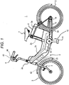
- Fig. 1 is a side view illustrating an electric bicycle 1 according to an example of an electric vehicle.
- left and right means left and right viewed in a riding condition.
- the electric bicycle 1, which is an electric vehicle illustrated in Fig. 1 is driven by resultant force of human power and driving force of an electric motor.
- a vehicle body 2 of the electric bicycle 1 includes a head pipe 2a, a down tube 2b, a seat tube 2c, a pair of left and right chain stays 2d, and a pair of left and right seat stays 2e.
- the down tube 2b obliquely extends downward from a rear side of the head pipe 2a.
- the seat tube 2c extends upward from a rear portion of the down tube 2b.
- the pair of left and right chain stays 2d are connected to the rear portion of the down tube 2b.
- the pair of left and right seat stays 2e connect an upper portion of the seat tube 2c with rear end portions of the chain stays 2d in an approximately triangular shape.
- a front fork 4 is supported on the head pipe 2a in such a manner as to be rotatable in left and right directions.
- a front wheel 3 is supported on a lower end of the front fork 4 in a rotatable manner.
- a wheel speed sensor 42 that detects a wheel speed V of the front wheel 3 is attached to the front fork 4.
- a steering handle 6 is attached to an upper end of the head pipe 2a in such a manner as to be rotatable in left and right directions.
- a transmission operator 43 and a push-walking assist switch 44 are attached to the steering handle 6.
- a saddle 7 is attached to an upper end of the seat tube 2c.
- a battery 8 is mounted on a rear side of the seat tube 2c.
- a rear wheel 5 is supported on rear ends of the chain stays 2d in a rotatable manner.
- a power unit 10 is provided on a lower side of the down tube 2b.
- the power unit 10 includes a pedal 11 to which a stepping force from a rider is input, an electric motor 12 that is driven by the battery 8, a transmission 14 and a chain 15.
- the power unit 10 further includes a controller 20 that controls driving of the electric motor 12.
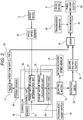
- Fig. 2 is a system block diagram of the electric bicycle 1.
- the stepping force from the pedal 11 is input into the chain 15 via a first one-way clutch 22.
- the driving force of the electric motor 12 is input into the chain 15 via a reduction gear 23 and a second one-way clutch 24.
- the resultant force of the stepping force from the pedal 11 and the driving force from the electric motor 12 acts on the chain 15.
- the resultant force of the stepping force from the pedal 11 and the driving force from the electric motor 12 is transmitted to the transmission 14.
- Output of the transmission 14 is transmitted to the rear wheel 5 via a third one-way clutch 25.
- the transmission 14 can be switched to a low gear, a middle gear and a high gear in an ascending order of a transmission gear ratio, for example.
- the transmission gear ratio of the transmission 14 can be switched by the transmission operator 43 that is attached to the steering handle 6.
- the transmission 14 transmits the driving force transmitted from the chain 15 to the rear wheel 5 in response to the selected transmission gear ratio.
- the controller 20 includes a memory 21 and a control unit 30.
- the control unit 30 has a central processing unit (CPU) that performs various processing operations.
- the memory 21 has a read-only memory (ROM) that stores various programs executed by the control unit 30, and a random access memory (RAM) that is used as a work area for data storage and program execution.
- ROM read-only memory
- RAM random access memory
- the control unit 30 includes a target motor power determination unit 31, a target motor torque calculation unit 32 and a motor control unit 33.
- a target motor power determination unit 31 output of the wheel speed sensor 42 that detects the wheel speed V of the front wheel 3, output of the push-walking assist switch 44, and output of a torque sensor 45 that detects the stepping force from the pedal 11 can be input.
- Output of a motor rotation speed sensor 41 can be input into the target motor torque calculation unit 32.
- Fig. 3 is a flowchart illustrating a method for controlling the electric motor 12 that is executed when the electric bicycle 1 runs while being assisted (hereinafter, “assisted running”).
- assisted running the driving force of the electric motor 12 is transmitted to the rear wheel 5 and the driving force, which is larger than a pedal stepping force of the rider, is generated in the rear wheel 5.
- the control of the electric motor 12 by the control unit 30 at this time is referred to as "assisted running control”.
- the control unit 30 determines that an assisted running mode of the electric bicycle 1 is ON.
- the control unit 30 starts the assisted running control of the electric motor 12 (step S01).
- step S02 the driving of the electric motor 12 is started and the target motor power determination unit 31 acquires motor rotation speed M of the electric motor 12 from the motor rotation speed sensor 41 that functions as a motor rotation speed acquisition unit.
- the target motor power determination unit 31 compares the acquired motor rotation speed M with a predetermined lower limit value ML (step S03). If the motor rotation speed M is less than the predetermined lower limit value ML (step S03: Yes), the target motor torque calculation unit 32 sets a target motor torque t as a constant value t1 regardless of the motor rotation speed M (step S04). Then, the motor control unit 33 drives the electric motor 12 at the target motor torque t1 (step S09).
- a command value that is input into the electric motor 12 is calculated so that an output torque of the electric motor 12 is equal to t.
- the command value is expressed as a current value
- the motor control unit 33 calculates a current value according to the target motor torque t and the current value is sent to the electric motor 12 as a command.
- step S03 if the motor rotation speed M is equal to or larger than the lower limit value ML (step S03: No), the target motor power determination unit 31 also compares the motor rotation speed M with a predetermined upper limit value MH (step S05).
- step S05 If the motor rotation speed M is equal to or larger than the upper limit value MH (step S05: No), the target motor torque calculation unit 32 sets the target motor torque t to be zero regardless of the motor rotation speed M. Then, the motor control unit 33 controls so that the target motor torque t of the electric motor 12 is equal to zero (step S06).
- the target motor power determination unit 31 determines a target motor power W (step S07).
- the target motor power W is determined as follows.
- Fig. 4 is a map defining a relationship between the wheel speed V of the front wheel 3 and the target motor power W.
- the target motor power determination unit 31 determines the target motor power W from the relationship with the wheel speed V based on the map of Fig. 4 (step S07).
- the target motor power W is increased monotonically in response to an increase in the wheel speed V.
- the target motor power W is decreased in response to the increase in the wheel speed V.
- the threshold value V1 can be set to be any value.
- the regulation speed V2 is a value determined by, for example, laws or regulations. According to the laws or regulations, no assist force is generated when the speed of the electric bicycle 1 is equal to or higher than a predetermined speed.
- step S01 When the motor control unit 33 drives the electric motor 12 at the target motor torque t, the control unit 30 returns to step S01, and repeats the above steps S01 to S09 as long as the assisted running mode remains ON.
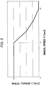
- Fig. 5 is a graph illustrating a relationship between the wheel speed V of the front wheel 3 and a wheel torque T applied to the rear wheel 5 during the assisted running when the above-described control is executed.
- the wheel torque T is a constant value regardless of a transmission gear ratio G.
- the wheel torque T is a constant value T1.
- the wheel torque T decreases toward the regulation speed V2, and in an area in which the wheel speed V is equal to or larger than the regulation speed V2, the wheel torque T is zero.
- Formula (3) shows that the wheel torque T is not influenced by the transmission gear ratio G.
- the wheel torque T1 is, as shown in Fig. 4 , a gradient in the area in which the wheel speed V is equal to or larger than zero and less than the threshold value V1.
- the constant wheel torque corresponding to the target motor power W is transmitted from the electric motor 12 to the rear wheel 5.
- the constant wheel torque corresponding to the target motor power W acts on the rear wheel 5.
- the behavior of the electric bicycle 1 is stable regardless of the transmission gear ratio G. Therefore, the electric bicycle 1 is provided with a high riding comfort and stable behavior regardless of the transmission gear ratio G.
- Fig. 6 is a map used to determine a target motor torque in a method for controlling an electric motor according to a comparative example.
- the electric motor is controlled in such a manner that a predetermined torque is output in response to pedal stepping force P1, P2, and P3.
- the stepping force P1, P2, and P3 have a relationship of P1>P2>P3.
- Fig. 7 is a view illustrating a relationship between wheel speed V and wheel torque T that acts on a wheel to which driving force of the electric motor is transmitted in an electric bicycle whose electric motor is controlled as illustrated in Fig. 6 .
- the target motor torque of the electric motor is determined in response to the stepping force.
- the wheel torque T that is input into the rear wheel is varied in response to the transmission gear ratio of the transmission.
- the transmission gear ratio of a low gear is 0.5
- the transmission gear ratio of a high gear is 1.5 in the transmission 14.
- the wheel torque T that acts on the rear wheel when the low gear is selected in the transmission 14 is twice the wheel torque that acts on the rear wheel when the middle gear is selected.
- the wheel torque T that acts on the rear wheel is three times the wheel torque T that acts on the rear wheel when the high gear is selected.
- the wheel torque T varies significantly when the transmission gear ratio differs as illustrated in Fig. 7 .
- the wheel torque T that is larger than what is expected by the rider is abruptly input into the rear wheel. Therefore, the larger acceleration force abruptly acts on the rider, and the behavior of the electric bicycle becomes unstable.
- Fig. 8 is a map illustrating a relationship between the stepping force P1, P2, and P3, the wheel speed V and the target motor power W in the method for controlling the electric vehicle motor according to the embodiment.
- the stepping force P1, P2 and P3 have the relationship of P1>P2>P3.
- the target motor power W is determined to be small when the rider slightly steps on the pedal 11. Then, the relatively small wheel torque T is applied to the rear wheel 5. In other words, the assist amount is small. In contrast, the target motor power W is determined to be large when the rider mightily steps on the pedal 11. Then, the relatively large wheel torque T is applied to the rear wheel 5. In other words, the assist amount is large.
- the assist amount of the electric motor 12 can be adjusted in response to the pedal stepping force. Further, even in this case, the wheel torque T that acts on the rear wheel 5 does not depend on the transmission gear ratio G as described above. Therefore, the behavior of the electric bicycle 1 is stable even in a case where the assist amount is large.
- step S03 before the target motor power W is determined in response to the wheel speed V, when the motor rotation speed M is less than the lower limit value ML (step S03: Yes), the target motor torque t is set as the constant value t1 regardless of the motor rotation speed M (step S04) and the electric motor 12 is driven (step S09).
- step S07 it is prevented the target motor torque t from being setting excessive value when the motor rotation speed M is low. Therefore, it is possible to prevent the large wheel torque T from acting on the rear wheel 5 when the motor rotation speed M is low, and it is possible to provide the electric bicycle 1 with a stable riding comfort.
- step S05 when the motor rotation speed M is equal to or larger than the upper limit value MH (step S05: No), the target motor torque t is set to be zero. Therefore, the rear wheel 5 is prevented from rotating at a high speed with the rotation speed being equal to or larger than a predetermined value.
- the target motor power W is gradually decreased near the regulation speed V2 so that the target motor power W becomes zero at the regulation speed V2. In this manner, even if the wheel speed V frequently changes around the regulation speed V2, the target motor power W changes slightly, and the behavior of the electric bicycle 1 is stable.
- the electric motor 12 begins to rotate from a stopped state, there is a concern that behavior of the vehicle could becomes less stable, depending upon how the driving force is transmitted from the electric motor 12 to the chain 15. In other words, the electric motor 12 is driven in a no-load state until the driving force of the electric motor 12 is transmitted to the chain 15. Therefore, it is likely that the electric motor 12 rotates at a high speed. If the electric motor 12 that rotates at the high speed is connected to the chain 15 that rotates at a relatively low speed or is in a stopped state, the rider is bothered by a feeling of strangeness.
- the control unit 30 calculates rotational acceleration A from the motor rotation speed M at the moment immediately after the rotation of the electric motor 12.
- the control unit 30 determines that the electric motor 12 is in a no-load rotation period.
- the target motor power determination unit 31 sets the target motor power W to be zero.
- the control unit 30 can define the no-load rotation period as a period from the stopped state of the electric motor 12 until when the rotational acceleration A has a negative value.
- the transmission gear ratio G of the transmission 14 exerts no influence until the electric motor 12 is connected to the chain 15. Therefore, the wheel torque T that acts on the rear wheel 5 is not influenced by the transmission gear ratio G no matter what function is set for the target motor power W of the electric motor 12.
- the method for controlling the electric vehicle motor according to the present invention is applied to an example in which the rider is ride on the vehicle and the vehicle is running while being assisted.
- the present invention may be applied to controlling of the electric vehicle motor in push-walking assist.
- Fig. 9 is a flowchart related to control during the push-walking assist. Fig. 9 is substantially the same as the flowchart of Fig. 3 , which is related to the assisted running.
- step S01 when input from the push-walking assist switch 44 is input into the target motor power determination unit 31, the target motor power determination unit 31 determines that the electric bicycle 1 is in the push-walking assist mode.
- the push-walking assist switch 44 may be an ON/OFF switch that is capable of switching only ON/OFF of the assist mode, and may be the input means that is capable of setting strength of an assist force in stages.
- the target motor power W be set according to the stage of the input from the input means so that the assist force increases. In this manner, the stronger assist force can act on the rear wheel 5 on a steep hill, and it is possible to achieve a good feeling of being assisted.
- throttle devices As the input means that sets the assist force in stages, throttle devices, slide switches, rotating levers, pressure-sensitive switches, and various sensors can be employed.
- sensors a tilt angle sensor that detects a tilt angle of a road surface may be used, and the target motor power W may be set in such a manner that the assist force which is increased in proportion to the tilt angle acts on the rear wheel 5 in response to the input of the tilt angle sensor.
- the constant wheel torque T acts on the rear wheel 5 on each occasion. In this manner, even when a low transmission gear ratio is selected in the transmission 14, the wheel torque T that is larger than what is expected does not act, and thus the rider pushes and walks the electric bicycle while the behavior of the electric bicycle remains stable state.
- the method for controlling the electric vehicle motor according to the present invention is useful in that the constant wheel torque T can act on the rear wheel 5 regardless of the transmission gear ratio.
- the wheel speed sensor is not provided in the rear wheel 5 that is a driving wheel, but the wheel speed sensor 42 is provided in the front wheel 3.
- the wheel speed V is detected as between zero and a low speed.
- the push-walking assist mode is turned ON, the assist force from the electric motor 12 is input into the rear wheel 5 in the no-load state. In this case, there is a concern that the rotation speed of the rear wheel 5 could increase unexpectedly.
- the target motor torque t is set to be zero (step S06) when the motor rotation speed M reaches the predetermined upper limit value MH (step S05: No). In this manner, rotational speed of the rear wheel 5 is prevented from becoming excessively high. Therefore, even if the rear wheel 5 alone is lifted, the rear wheel 5 is prevented from rotating at a high speed, and thus the electric bicycle 1 with stable behavior can be provided.
- the method for controlling the electric vehicle motor, a power unit for an electric vehicle, and an electric vehicle according to the present invention are not limited to the embodiment and the modification example described above, but appropriate modifications and improvements are possible.
- a power-assisted bicycle is described as an example of the electric vehicle.
- the present invention is not limited thereto.
- the present invention can be applied to an electric vehicle in which the output of the electric motor is transmitted to the ground surface via the transmission, such as an electric scooter, a hybrid car, and an electric car.
- the pedal stepping force from the rider and the driving force of the electric motor 12 act on the rear wheel 5.
- the driving force may be configured to be input into the front wheel 3.
- the wheel on which the pedal stepping force acts and the wheel on which the driving force of the electric motor 12 acts may be different from each other.
- the electric motor 12 is provided on the lower side of the down tube 2b.
- the electric motor 12 may be provided inside a hub of the rear wheel 5 or inside a hub of the front wheel 3.
- the target motor power W is determined in response to the vehicle speed.
- the present invention is not limited thereto.
- the target motor power W can be determined in response to the input from any input means.
- the wheel speed sensor 42 that detects the wheel speed V described above as the input means detecting driving environment.
- the vehicle speed sensor that detects the vehicle speed as the driving environment
- an acceleration sensor that detects the acceleration as the driving environment
- a tilt angle sensor that detects the tilt angle of the ground surface as the driving environment, etc. In this manner, it is possible to provide the electric vehicle with the good feeling of being assisted in response to the driving environments without the rider being conscious thereof.
- the target motor power may be determined using the remaining amount of the battery as the driving environment. In this case, it is possible to make the output of the electric motor 12 uniform up to a target cruising distance allowing for the target cruising distance and the calculated capacity of the battery.
- the target motor power W may be determined according to the input from the input means that can be operated by a user.
- the input means ON/OFF switches, multi-staged switches such as slide switches that are capable of outputting a plurality of output values, throttle devices that are capable of outputting continuously changing output values, rotating levers, pressure-sensitive switches and the like can be used.
- the target motor power W can be set so that the large assist force is output when the large assist force is required by the user.
- control unit 30 is not limited to executing only the method for controlling the electric vehicle motor in which the target motor power W is determined so that the constant wheel torque T acts on the rear wheel 5 (motor driving wheel) regardless of the transmission gear ratio G as described above.
- control unit 30 may execute both of the method for controlling the electric vehicle motor in which the target motor torque t is determined according to the pedal stepping force P as illustrated in Fig. 6 and the method for controlling the electric vehicle motor according to the embodiment described above at the same time.
- control unit 30 may be configured in such a manner as to execute the control for determining the target motor torque t according to the pedal stepping force P during ordinary driving, and execute the controlling method in which the target motor power W is determined, regardless of the transmission gear ratio G, so that the constant wheel torque T acts on the motor driving wheel during the push-walking as described in the embodiment.
Landscapes
- Engineering & Computer Science (AREA)
- Transportation (AREA)
- Mechanical Engineering (AREA)
- Chemical & Material Sciences (AREA)
- Combustion & Propulsion (AREA)
- Power Engineering (AREA)
- Electric Propulsion And Braking For Vehicles (AREA)
- Hybrid Electric Vehicles (AREA)
Claims (10)
- Eine Methode zum Steuern eines elektrisch leistungsunterstützten Fahrzeuges, bei welchem die Ausgabe von einem Elektromotor (12) auf ein Rad (5) über ein Getriebe (14) mit einem variablen Übersetzungsverhältnis übertragen wird, dadurch gekennzeichnet, dass die Methode umfasst:erfassen der Motordrehzahl M des Elektromotors (12);bestimmen einer Soll-Motorleistung W, die als Ausgabe von dem Elektromotor (12) gewünscht ist, als eine Funktion von der Raddrehzahl oder der Fahrzeuggeschwindigkeit V des Elektrofahrzeuges, unabhängig von dem Getriebe-Übersetzungsverhältnis des Getriebes (14) undantreiben des Elektromotors (12) bei einem Soll-Motormoment t, das erhalten wird durch Teilen der Soll-Motorleistung W durch die Motordrehzahl M, um ein unterstützendes Radmoment bereitzustellen, das durch den Elektromotor (12) bereitgestellt wird, welches für alle Übersetzungsverhältnisse das gleiche ist.
- Die Methode zum Steuern eines Elektro-Fahrzeug-Motors gemäß Anspruch 1, wobei die Soll-Motorleistung W nahe der Soll-Geschwindigkeit V2 schrittweise verringert wird, so dass die Soll-Motorleistung W Null wird, wenn die Raddrehzahl oder die Fahrzeuggeschwindigkeit V der Soll-Geschwindigkeit V2 entspricht.
- Die Methode zum Steuern eines Elektro-Fahrzeug-Motors gemäß Anspruch 1, die Soll-Motorleistung W durch Berücksichtigung eines Neigungswinkels von einer StraßenOberfläche bestimmt wird.
- Die Methode zum Steuern eines Elektro-Fahrzeug-Motors gemäß Anspruch 1, die Soll-Motorleistung W durch Berücksichtigung einer Eingabe, die durch den Nutzer bedienbar ist, bestimmt wird.
- Die Methode zum Steuern eines Elektro-Fahrzeug-Motors gemäß einem der Ansprüche 1 bis 4, das Soll- Motormoment t als ein vorbestimmter Wert t1 eingestellt ist ohne Rücksicht auf die Motordrehzahl M, wenn die Motordrehzahl M niedriger ist als ein vorbestimmter unterer Grenzwert ML.
- Die Methode zum Steuern eines Elektro-Fahrzeug-Motors gemäß einem der Ansprüche 1 bis 5, das Soll- Motormoment t auf Null eingestellt ist ohne Rücksicht auf die Motordrehzahl M, wenn die Motordrehzahl M gleich oder größer als ein vorbestimmter oberer Grenzwert ML ist.
- Die Methode zum Steuern eines Elektro-Fahrzeug-Motors gemäß einem der Ansprüche 1 bis 6,
wobei die Rotationsbeschleunigung A des Elektromotors aus der Motordrehzahl M berechnet wird, und
wobei die Soll-Motorleistung W auf Null eingestellt ist, wenn die Rotationsbeschleunigung A gleich oder größer als ein oberer Grenzwert AH ist. - Die Methode zum Steuern eines Elektro-Fahrzeug-Motors gemäß einem der Ansprüche 1 bis 7, wobei die Soll-Motorleistung W bestimmt ist in Erwiderung auf die Eingabe von der Eingabe-Vorrichtung, die in einem Fahrzeug bereitgestellt wird.
- Eine Elektrofahrzeug-Leistungseinheit (10), in welcher die Ausgabe von einem Elektromotor (12) an ein Rad (5) über ein Getriebe (14) mit einem variablen Übersetzungsverhältnis übertragen wird, wobei die Elektrofahrzeug-Leistungseinheit (10) umfasst:den Elektromotor (12);eine Rotationsgeschwindigkeit-Erfassungseinheit (41), die die Motordrehzahl M des Elektromotors (12) erfasst;eine Soll-Motorleistung-Bestimmungseinheit (31), die die Soll-Motorleistung W des Elektromotors (12) bestimmt, die als Ausgabe von dem Elektromotor (12) gewünscht ist, als eine Funktion von der Raddrehzahl oder der Fahrzeuggeschwindigkeit V des Elektrofahrzeuges, unabhängig von dem Getriebe-Übersetzungsverhältnis des Getriebes (14); undeine Motor-Steuereinheit (33), die den Elektromotor (12) bei dem Soll-Motormoment t antreibt, um ein unterstützendes Radmoment bereitzustellen, das durch den Elektromotor (12) bereitgestellt wird, welches das gleiche ist für alle Übersetzungsverhältnisse.
- Ein Elektrofahrzeug umfassend eine Elektrofahrzeug-Leistungseinheit, wie die in Anspruch 9 gezeigte, darüber hinaus umfassend:das Getriebe (14) mit einem variablen Übersetzungsverhältnis, auf welches eine Antriebskraft des Elektromotors (12) übertragen wird;das Rad (5), auf welches die Antriebskraft des Elektromotors (12) über das Getriebe (14) übertragen wird.
Applications Claiming Priority (1)
| Application Number | Priority Date | Filing Date | Title |
|---|---|---|---|
| JP2012184613A JP6000020B2 (ja) | 2012-08-23 | 2012-08-23 | 鞍乗型電動車両、パワーユニットおよびパワーユニットの制御方法 |
Publications (3)
| Publication Number | Publication Date |
|---|---|
| EP2705973A2 EP2705973A2 (de) | 2014-03-12 |
| EP2705973A3 EP2705973A3 (de) | 2016-11-16 |
| EP2705973B1 true EP2705973B1 (de) | 2018-07-04 |
Family
ID=49080666
Family Applications (1)
| Application Number | Title | Priority Date | Filing Date |
|---|---|---|---|
| EP13181387.5A Active EP2705973B1 (de) | 2012-08-23 | 2013-08-22 | Elektrofahrzeug mit Spreizsitz, Stromversorgung und Verfahren zu deren Steuerung |
Country Status (3)
| Country | Link |
|---|---|
| EP (1) | EP2705973B1 (de) |
| JP (1) | JP6000020B2 (de) |
| ES (1) | ES2689803T3 (de) |
Cited By (1)
| Publication number | Priority date | Publication date | Assignee | Title |
|---|---|---|---|---|
| US11794852B2 (en) | 2019-12-27 | 2023-10-24 | Yamaha Hatsudoki Kabushiki Kaisha | Electric assisted bicycle, drive system thereof, and control method |
Families Citing this family (11)
| Publication number | Priority date | Publication date | Assignee | Title |
|---|---|---|---|---|
| EP3126184B1 (de) | 2014-04-04 | 2019-09-04 | Superpedestrian, Inc. | Systeme, verfahren und vorrichtungen zum betrieb elektrisch motorisierter fahrzeuge |
| JP6226825B2 (ja) * | 2014-06-20 | 2017-11-08 | ヤマハ発動機株式会社 | 電動補助自転車 |
| CN107206907B (zh) | 2014-11-24 | 2020-02-14 | 极步公司 | 机动车轮的设备和方法 |
| JP6933885B2 (ja) * | 2016-06-21 | 2021-09-08 | ヤマハ発動機株式会社 | 電動補助車両および補助出力制御システム |
| JP7343266B2 (ja) * | 2017-10-27 | 2023-09-12 | 株式会社シマノ | 人力駆動車両用制御装置 |
| JP7045238B2 (ja) * | 2018-03-29 | 2022-03-31 | 株式会社シマノ | 人力駆動車用制御装置 |
| CN110341474A (zh) * | 2019-08-05 | 2019-10-18 | 江苏吉麦新能源车业有限公司 | 一种电动车限速控制系统 |
| JP7349639B2 (ja) * | 2019-12-10 | 2023-09-25 | パナソニックIpマネジメント株式会社 | 電動自転車及び電動自転車の制御装置 |
| CN112477629B (zh) * | 2020-12-04 | 2022-07-22 | 晟盟(芦台)电机制造有限公司 | 一种电动自行车起步调速方法 |
| DE102021202501A1 (de) * | 2021-03-15 | 2022-09-15 | Robert Bosch Gesellschaft mit beschränkter Haftung | Verfahren und Vorrichtung zur Steuerung der Schiebehilfe eines Elektrofahrrads |
| CN113859416B (zh) * | 2021-09-06 | 2024-01-02 | 天津爱玛车业科技有限公司 | 电动车及其控制方法 |
Citations (1)
| Publication number | Priority date | Publication date | Assignee | Title |
|---|---|---|---|---|
| JPH1159557A (ja) * | 1997-08-26 | 1999-03-02 | Suzuki Motor Corp | 電動補助自転車 |
Family Cites Families (12)
| Publication number | Priority date | Publication date | Assignee | Title |
|---|---|---|---|---|
| JP3138795B2 (ja) * | 1994-09-12 | 2001-02-26 | 本田技研工業株式会社 | 自転車用アシストモータの制御方法 |
| TW451881U (en) * | 1995-08-30 | 2001-08-21 | Sanyo Electric Co | Electric vehicle |
| JPH09263290A (ja) * | 1996-03-27 | 1997-10-07 | Seiko Epson Corp | 電動自転車 |
| JPH09277978A (ja) * | 1996-04-12 | 1997-10-28 | Matsushita Electric Ind Co Ltd | 電気自転車 |
| ES2219719T3 (es) * | 1996-12-16 | 2004-12-01 | Honda Giken Kogyo Kabushiki Kaisha | Bicicleta asistida por motor. |
| JP3368816B2 (ja) * | 1997-12-05 | 2003-01-20 | 日産自動車株式会社 | ハイブリッド車の制御装置 |
| JPH11334677A (ja) * | 1998-05-27 | 1999-12-07 | Sony Corp | 補助動力源を備えた移動装置及びその制御方法 |
| JP2000118477A (ja) * | 1998-10-12 | 2000-04-25 | Sony Corp | 助力機能付き自転車 |
| DE19955863A1 (de) * | 1999-11-20 | 2001-05-23 | Heinzmann Gmbh Co Kg Fritz | Fahrzeug mit Elektrohilfsantrieb |
| JP2002095113A (ja) * | 2000-09-13 | 2002-03-29 | Nippon Yusoki Co Ltd | フォークリフトの制御装置 |
| JP3862175B2 (ja) * | 2003-07-29 | 2006-12-27 | 株式会社デンソー | 車両用変速装置 |
| EP2125469A2 (de) * | 2007-02-01 | 2009-12-02 | Fallbrook Technologies Inc. | System und verfahren zur getriebe- und/oder antriebsmotorsteuerung |
-
2012
- 2012-08-23 JP JP2012184613A patent/JP6000020B2/ja active Active
-
2013
- 2013-08-22 EP EP13181387.5A patent/EP2705973B1/de active Active
- 2013-08-22 ES ES13181387.5T patent/ES2689803T3/es active Active
Patent Citations (1)
| Publication number | Priority date | Publication date | Assignee | Title |
|---|---|---|---|---|
| JPH1159557A (ja) * | 1997-08-26 | 1999-03-02 | Suzuki Motor Corp | 電動補助自転車 |
Cited By (1)
| Publication number | Priority date | Publication date | Assignee | Title |
|---|---|---|---|---|
| US11794852B2 (en) | 2019-12-27 | 2023-10-24 | Yamaha Hatsudoki Kabushiki Kaisha | Electric assisted bicycle, drive system thereof, and control method |
Also Published As
| Publication number | Publication date |
|---|---|
| EP2705973A3 (de) | 2016-11-16 |
| JP6000020B2 (ja) | 2016-09-28 |
| ES2689803T3 (es) | 2018-11-15 |
| JP2014042434A (ja) | 2014-03-06 |
| EP2705973A2 (de) | 2014-03-12 |
Similar Documents
| Publication | Publication Date | Title |
|---|---|---|
| EP2705973B1 (de) | Elektrofahrzeug mit Spreizsitz, Stromversorgung und Verfahren zu deren Steuerung | |
| CN104718100B (zh) | 电动车辆的再生制动控制系统 | |
| EP2711285B1 (de) | Elektrisches Fahrrad und Steuerverfahren dafür | |
| EP2476605B1 (de) | Zweirädriges Fahrzeug, Lagestabilisierungsvorrichtung und Lagestabilisierungsverfahren | |
| US10421519B2 (en) | Bicycle controller | |
| EP2377713A1 (de) | Fahrrad mit elektrischem Hilfsmotor | |
| JP2015535767A (ja) | 車の制御システム及び制御方法 | |
| WO2014064729A1 (ja) | 電動車両の回生ブレーキ制御システム | |
| EP2783970B1 (de) | Steuerung für Elektrofahrrad, Antriebseinheit für Elektrofahrrad und Elektrofahrrad | |
| US12162565B2 (en) | Human-powered vehicle control device | |
| CN103010294B (zh) | Esc-mdps综合控制装置及其方法 | |
| WO2017175529A1 (ja) | 電動アシスト自転車、及び踏力アシストシステム | |
| US12565284B2 (en) | Control device for human-powered vehicle | |
| JP2017154564A (ja) | 電動アシスト自転車 | |
| EP3533700B1 (de) | Unterstützungskraftberechnungsverfahren für ein elektrisch unterstütztes fahrrad, elektrisch unterstützte fahrradsteuereinheit, elektrisch unterstützte fahrradantriebseinheit und elektrisch unterstütztes fahrrad | |
| JP4744283B2 (ja) | 補助動力付き車両 | |
| JP3861068B2 (ja) | 自動駐車装置 | |
| JP2020048261A (ja) | 電動車両 | |
| US20240025511A1 (en) | Method for controlling an electric drive of a two-wheeled vehicle and control device for performing the method | |
| JP5019013B1 (ja) | 車両の駆動制御装置 | |
| JP2005335534A (ja) | 補助動力装置付き車両 | |
| JP2004066993A (ja) | 駐車ブレーキ装置 | |
| WO2023053021A1 (ja) | 制御装置及び制御方法 | |
| US11807336B2 (en) | Human-powered vehicle control device | |
| JP7765599B2 (ja) | 制御装置、制御方法、及び、制御システム |
Legal Events
| Date | Code | Title | Description |
|---|---|---|---|
| PUAI | Public reference made under article 153(3) epc to a published international application that has entered the european phase |
Free format text: ORIGINAL CODE: 0009012 |
|
| AK | Designated contracting states |
Kind code of ref document: A2 Designated state(s): AL AT BE BG CH CY CZ DE DK EE ES FI FR GB GR HR HU IE IS IT LI LT LU LV MC MK MT NL NO PL PT RO RS SE SI SK SM TR |
|
| AX | Request for extension of the european patent |
Extension state: BA ME |
|
| PUAL | Search report despatched |
Free format text: ORIGINAL CODE: 0009013 |
|
| AK | Designated contracting states |
Kind code of ref document: A3 Designated state(s): AL AT BE BG CH CY CZ DE DK EE ES FI FR GB GR HR HU IE IS IT LI LT LU LV MC MK MT NL NO PL PT RO RS SE SI SK SM TR |
|
| AX | Request for extension of the european patent |
Extension state: BA ME |
|
| RIC1 | Information provided on ipc code assigned before grant |
Ipc: B60L 15/20 20060101ALI20161007BHEP Ipc: B62M 6/55 20100101ALI20161007BHEP Ipc: B60L 11/00 20060101AFI20161007BHEP Ipc: B62M 6/45 20100101ALI20161007BHEP Ipc: B62M 6/50 20100101ALI20161007BHEP |
|
| 17P | Request for examination filed |
Effective date: 20170307 |
|
| RBV | Designated contracting states (corrected) |
Designated state(s): AL AT BE BG CH CY CZ DE DK EE ES FI FR GB GR HR HU IE IS IT LI LT LU LV MC MK MT NL NO PL PT RO RS SE SI SK SM TR |
|
| 17Q | First examination report despatched |
Effective date: 20170518 |
|
| GRAP | Despatch of communication of intention to grant a patent |
Free format text: ORIGINAL CODE: EPIDOSNIGR1 |
|
| INTG | Intention to grant announced |
Effective date: 20180219 |
|
| GRAS | Grant fee paid |
Free format text: ORIGINAL CODE: EPIDOSNIGR3 |
|
| GRAA | (expected) grant |
Free format text: ORIGINAL CODE: 0009210 |
|
| AK | Designated contracting states |
Kind code of ref document: B1 Designated state(s): AL AT BE BG CH CY CZ DE DK EE ES FI FR GB GR HR HU IE IS IT LI LT LU LV MC MK MT NL NO PL PT RO RS SE SI SK SM TR |
|
| REG | Reference to a national code |
Ref country code: GB Ref legal event code: FG4D |
|
| REG | Reference to a national code |
Ref country code: CH Ref legal event code: EP |
|
| REG | Reference to a national code |
Ref country code: AT Ref legal event code: REF Ref document number: 1014132 Country of ref document: AT Kind code of ref document: T Effective date: 20180715 |
|
| REG | Reference to a national code |
Ref country code: IE Ref legal event code: FG4D |
|
| REG | Reference to a national code |
Ref country code: DE Ref legal event code: R096 Ref document number: 602013039629 Country of ref document: DE |
|
| REG | Reference to a national code |
Ref country code: NL Ref legal event code: FP |
|
| REG | Reference to a national code |
Ref country code: FR Ref legal event code: PLFP Year of fee payment: 6 |
|
| REG | Reference to a national code |
Ref country code: ES Ref legal event code: FG2A Ref document number: 2689803 Country of ref document: ES Kind code of ref document: T3 Effective date: 20181115 |
|
| REG | Reference to a national code |
Ref country code: LT Ref legal event code: MG4D |
|
| REG | Reference to a national code |
Ref country code: DE Ref legal event code: R079 Ref document number: 602013039629 Country of ref document: DE Free format text: PREVIOUS MAIN CLASS: B60L0011000000 Ipc: B60L0050000000 |
|
| REG | Reference to a national code |
Ref country code: AT Ref legal event code: MK05 Ref document number: 1014132 Country of ref document: AT Kind code of ref document: T Effective date: 20180704 |
|
| PG25 | Lapsed in a contracting state [announced via postgrant information from national office to epo] |
Ref country code: GR Free format text: LAPSE BECAUSE OF FAILURE TO SUBMIT A TRANSLATION OF THE DESCRIPTION OR TO PAY THE FEE WITHIN THE PRESCRIBED TIME-LIMIT Effective date: 20181005 Ref country code: CZ Free format text: LAPSE BECAUSE OF FAILURE TO SUBMIT A TRANSLATION OF THE DESCRIPTION OR TO PAY THE FEE WITHIN THE PRESCRIBED TIME-LIMIT Effective date: 20180704 Ref country code: SE Free format text: LAPSE BECAUSE OF FAILURE TO SUBMIT A TRANSLATION OF THE DESCRIPTION OR TO PAY THE FEE WITHIN THE PRESCRIBED TIME-LIMIT Effective date: 20180704 Ref country code: PL Free format text: LAPSE BECAUSE OF FAILURE TO SUBMIT A TRANSLATION OF THE DESCRIPTION OR TO PAY THE FEE WITHIN THE PRESCRIBED TIME-LIMIT Effective date: 20180704 Ref country code: LT Free format text: LAPSE BECAUSE OF FAILURE TO SUBMIT A TRANSLATION OF THE DESCRIPTION OR TO PAY THE FEE WITHIN THE PRESCRIBED TIME-LIMIT Effective date: 20180704 Ref country code: RS Free format text: LAPSE BECAUSE OF FAILURE TO SUBMIT A TRANSLATION OF THE DESCRIPTION OR TO PAY THE FEE WITHIN THE PRESCRIBED TIME-LIMIT Effective date: 20180704 Ref country code: FI Free format text: LAPSE BECAUSE OF FAILURE TO SUBMIT A TRANSLATION OF THE DESCRIPTION OR TO PAY THE FEE WITHIN THE PRESCRIBED TIME-LIMIT Effective date: 20180704 Ref country code: AT Free format text: LAPSE BECAUSE OF FAILURE TO SUBMIT A TRANSLATION OF THE DESCRIPTION OR TO PAY THE FEE WITHIN THE PRESCRIBED TIME-LIMIT Effective date: 20180704 Ref country code: BG Free format text: LAPSE BECAUSE OF FAILURE TO SUBMIT A TRANSLATION OF THE DESCRIPTION OR TO PAY THE FEE WITHIN THE PRESCRIBED TIME-LIMIT Effective date: 20181004 Ref country code: NO Free format text: LAPSE BECAUSE OF FAILURE TO SUBMIT A TRANSLATION OF THE DESCRIPTION OR TO PAY THE FEE WITHIN THE PRESCRIBED TIME-LIMIT Effective date: 20181004 Ref country code: IS Free format text: LAPSE BECAUSE OF FAILURE TO SUBMIT A TRANSLATION OF THE DESCRIPTION OR TO PAY THE FEE WITHIN THE PRESCRIBED TIME-LIMIT Effective date: 20181104 |
|
| PG25 | Lapsed in a contracting state [announced via postgrant information from national office to epo] |
Ref country code: AL Free format text: LAPSE BECAUSE OF FAILURE TO SUBMIT A TRANSLATION OF THE DESCRIPTION OR TO PAY THE FEE WITHIN THE PRESCRIBED TIME-LIMIT Effective date: 20180704 Ref country code: HR Free format text: LAPSE BECAUSE OF FAILURE TO SUBMIT A TRANSLATION OF THE DESCRIPTION OR TO PAY THE FEE WITHIN THE PRESCRIBED TIME-LIMIT Effective date: 20180704 Ref country code: LV Free format text: LAPSE BECAUSE OF FAILURE TO SUBMIT A TRANSLATION OF THE DESCRIPTION OR TO PAY THE FEE WITHIN THE PRESCRIBED TIME-LIMIT Effective date: 20180704 |
|
| REG | Reference to a national code |
Ref country code: CH Ref legal event code: PL |
|
| REG | Reference to a national code |
Ref country code: DE Ref legal event code: R097 Ref document number: 602013039629 Country of ref document: DE |
|
| PG25 | Lapsed in a contracting state [announced via postgrant information from national office to epo] |
Ref country code: EE Free format text: LAPSE BECAUSE OF FAILURE TO SUBMIT A TRANSLATION OF THE DESCRIPTION OR TO PAY THE FEE WITHIN THE PRESCRIBED TIME-LIMIT Effective date: 20180704 Ref country code: RO Free format text: LAPSE BECAUSE OF FAILURE TO SUBMIT A TRANSLATION OF THE DESCRIPTION OR TO PAY THE FEE WITHIN THE PRESCRIBED TIME-LIMIT Effective date: 20180704 Ref country code: LU Free format text: LAPSE BECAUSE OF NON-PAYMENT OF DUE FEES Effective date: 20180822 Ref country code: LI Free format text: LAPSE BECAUSE OF NON-PAYMENT OF DUE FEES Effective date: 20180831 Ref country code: CH Free format text: LAPSE BECAUSE OF NON-PAYMENT OF DUE FEES Effective date: 20180831 Ref country code: MC Free format text: LAPSE BECAUSE OF FAILURE TO SUBMIT A TRANSLATION OF THE DESCRIPTION OR TO PAY THE FEE WITHIN THE PRESCRIBED TIME-LIMIT Effective date: 20180704 |
|
| PLBE | No opposition filed within time limit |
Free format text: ORIGINAL CODE: 0009261 |
|
| REG | Reference to a national code |
Ref country code: BE Ref legal event code: MM Effective date: 20180831 |
|
| STAA | Information on the status of an ep patent application or granted ep patent |
Free format text: STATUS: NO OPPOSITION FILED WITHIN TIME LIMIT |
|
| PG25 | Lapsed in a contracting state [announced via postgrant information from national office to epo] |
Ref country code: SK Free format text: LAPSE BECAUSE OF FAILURE TO SUBMIT A TRANSLATION OF THE DESCRIPTION OR TO PAY THE FEE WITHIN THE PRESCRIBED TIME-LIMIT Effective date: 20180704 Ref country code: DK Free format text: LAPSE BECAUSE OF FAILURE TO SUBMIT A TRANSLATION OF THE DESCRIPTION OR TO PAY THE FEE WITHIN THE PRESCRIBED TIME-LIMIT Effective date: 20180704 Ref country code: SM Free format text: LAPSE BECAUSE OF FAILURE TO SUBMIT A TRANSLATION OF THE DESCRIPTION OR TO PAY THE FEE WITHIN THE PRESCRIBED TIME-LIMIT Effective date: 20180704 |
|
| 26N | No opposition filed |
Effective date: 20190405 |
|
| PG25 | Lapsed in a contracting state [announced via postgrant information from national office to epo] |
Ref country code: SI Free format text: LAPSE BECAUSE OF FAILURE TO SUBMIT A TRANSLATION OF THE DESCRIPTION OR TO PAY THE FEE WITHIN THE PRESCRIBED TIME-LIMIT Effective date: 20180704 Ref country code: BE Free format text: LAPSE BECAUSE OF NON-PAYMENT OF DUE FEES Effective date: 20180831 |
|
| PGFP | Annual fee paid to national office [announced via postgrant information from national office to epo] |
Ref country code: NL Payment date: 20190821 Year of fee payment: 7 |
|
| PGFP | Annual fee paid to national office [announced via postgrant information from national office to epo] |
Ref country code: FR Payment date: 20190822 Year of fee payment: 7 Ref country code: ES Payment date: 20190924 Year of fee payment: 7 Ref country code: IT Payment date: 20190829 Year of fee payment: 7 |
|
| PGFP | Annual fee paid to national office [announced via postgrant information from national office to epo] |
Ref country code: GB Payment date: 20190821 Year of fee payment: 7 |
|
| PG25 | Lapsed in a contracting state [announced via postgrant information from national office to epo] |
Ref country code: MT Free format text: LAPSE BECAUSE OF NON-PAYMENT OF DUE FEES Effective date: 20180822 |
|
| PG25 | Lapsed in a contracting state [announced via postgrant information from national office to epo] |
Ref country code: TR Free format text: LAPSE BECAUSE OF FAILURE TO SUBMIT A TRANSLATION OF THE DESCRIPTION OR TO PAY THE FEE WITHIN THE PRESCRIBED TIME-LIMIT Effective date: 20180704 |
|
| PG25 | Lapsed in a contracting state [announced via postgrant information from national office to epo] |
Ref country code: HU Free format text: LAPSE BECAUSE OF FAILURE TO SUBMIT A TRANSLATION OF THE DESCRIPTION OR TO PAY THE FEE WITHIN THE PRESCRIBED TIME-LIMIT; INVALID AB INITIO Effective date: 20130822 Ref country code: PT Free format text: LAPSE BECAUSE OF FAILURE TO SUBMIT A TRANSLATION OF THE DESCRIPTION OR TO PAY THE FEE WITHIN THE PRESCRIBED TIME-LIMIT Effective date: 20180704 |
|
| PG25 | Lapsed in a contracting state [announced via postgrant information from national office to epo] |
Ref country code: CY Free format text: LAPSE BECAUSE OF FAILURE TO SUBMIT A TRANSLATION OF THE DESCRIPTION OR TO PAY THE FEE WITHIN THE PRESCRIBED TIME-LIMIT Effective date: 20180704 Ref country code: IE Free format text: LAPSE BECAUSE OF NON-PAYMENT OF DUE FEES Effective date: 20180822 Ref country code: MK Free format text: LAPSE BECAUSE OF NON-PAYMENT OF DUE FEES Effective date: 20180704 |
|
| REG | Reference to a national code |
Ref country code: NL Ref legal event code: MM Effective date: 20200901 |
|
| GBPC | Gb: european patent ceased through non-payment of renewal fee |
Effective date: 20200822 |
|
| PG25 | Lapsed in a contracting state [announced via postgrant information from national office to epo] |
Ref country code: IT Free format text: LAPSE BECAUSE OF NON-PAYMENT OF DUE FEES Effective date: 20200822 Ref country code: FR Free format text: LAPSE BECAUSE OF NON-PAYMENT OF DUE FEES Effective date: 20200831 |
|
| PG25 | Lapsed in a contracting state [announced via postgrant information from national office to epo] |
Ref country code: GB Free format text: LAPSE BECAUSE OF NON-PAYMENT OF DUE FEES Effective date: 20200822 |
|
| PG25 | Lapsed in a contracting state [announced via postgrant information from national office to epo] |
Ref country code: NL Free format text: LAPSE BECAUSE OF NON-PAYMENT OF DUE FEES Effective date: 20200901 |
|
| REG | Reference to a national code |
Ref country code: ES Ref legal event code: FD2A Effective date: 20220110 |
|
| PG25 | Lapsed in a contracting state [announced via postgrant information from national office to epo] |
Ref country code: ES Free format text: LAPSE BECAUSE OF NON-PAYMENT OF DUE FEES Effective date: 20200823 |
|
| PGFP | Annual fee paid to national office [announced via postgrant information from national office to epo] |
Ref country code: DE Payment date: 20250820 Year of fee payment: 13 |