EP2706169A2 - Dispositif destiné au recouvrement d'une ouverture d'entrée dans une baignoire de balnéothérapie - Google Patents
Dispositif destiné au recouvrement d'une ouverture d'entrée dans une baignoire de balnéothérapie Download PDFInfo
- Publication number
- EP2706169A2 EP2706169A2 EP13181239.8A EP13181239A EP2706169A2 EP 2706169 A2 EP2706169 A2 EP 2706169A2 EP 13181239 A EP13181239 A EP 13181239A EP 2706169 A2 EP2706169 A2 EP 2706169A2
- Authority
- EP
- European Patent Office
- Prior art keywords
- cover
- profile
- film
- roller
- film unit
- Prior art date
- Legal status (The legal status is an assumption and is not a legal conclusion. Google has not performed a legal analysis and makes no representation as to the accuracy of the status listed.)
- Granted
Links
- 241000446313 Lamella Species 0.000 claims description 11
- 238000009499 grossing Methods 0.000 claims description 10
- 230000005540 biological transmission Effects 0.000 claims description 6
- 239000011888 foil Substances 0.000 description 5
- RYGMFSIKBFXOCR-UHFFFAOYSA-N Copper Chemical compound [Cu] RYGMFSIKBFXOCR-UHFFFAOYSA-N 0.000 description 4
- 230000008901 benefit Effects 0.000 description 4
- 238000000034 method Methods 0.000 description 4
- 210000004197 pelvis Anatomy 0.000 description 4
- 230000008569 process Effects 0.000 description 4
- XLYOFNOQVPJJNP-UHFFFAOYSA-N water Substances O XLYOFNOQVPJJNP-UHFFFAOYSA-N 0.000 description 4
- 229910000831 Steel Inorganic materials 0.000 description 3
- 238000010276 construction Methods 0.000 description 3
- 238000006073 displacement reaction Methods 0.000 description 3
- 238000007789 sealing Methods 0.000 description 3
- 239000010959 steel Substances 0.000 description 3
- 239000004020 conductor Substances 0.000 description 2
- 229910052802 copper Inorganic materials 0.000 description 2
- 239000010949 copper Substances 0.000 description 2
- 238000012544 monitoring process Methods 0.000 description 2
- 229920001343 polytetrafluoroethylene Polymers 0.000 description 2
- 239000004810 polytetrafluoroethylene Substances 0.000 description 2
- 230000007480 spreading Effects 0.000 description 2
- 238000003892 spreading Methods 0.000 description 2
- 241000238631 Hexapoda Species 0.000 description 1
- 229920006328 Styrofoam Polymers 0.000 description 1
- 239000004809 Teflon Substances 0.000 description 1
- 229920006362 Teflon® Polymers 0.000 description 1
- XAGFODPZIPBFFR-UHFFFAOYSA-N aluminium Chemical compound [Al] XAGFODPZIPBFFR-UHFFFAOYSA-N 0.000 description 1
- 229910052782 aluminium Inorganic materials 0.000 description 1
- 238000003287 bathing Methods 0.000 description 1
- 238000011109 contamination Methods 0.000 description 1
- 238000001816 cooling Methods 0.000 description 1
- 230000006378 damage Effects 0.000 description 1
- 239000013013 elastic material Substances 0.000 description 1
- 210000003414 extremity Anatomy 0.000 description 1
- 238000001125 extrusion Methods 0.000 description 1
- 230000006870 function Effects 0.000 description 1
- 239000003365 glass fiber Substances 0.000 description 1
- 230000012447 hatching Effects 0.000 description 1
- 239000011810 insulating material Substances 0.000 description 1
- 238000009413 insulation Methods 0.000 description 1
- 238000012423 maintenance Methods 0.000 description 1
- 238000004519 manufacturing process Methods 0.000 description 1
- 210000003903 pelvic floor Anatomy 0.000 description 1
- 229920000642 polymer Polymers 0.000 description 1
- 229920006327 polystyrene foam Polymers 0.000 description 1
- -1 polytetrafluoroethylene Polymers 0.000 description 1
- 230000002265 prevention Effects 0.000 description 1
- 230000004044 response Effects 0.000 description 1
- 238000006748 scratching Methods 0.000 description 1
- 230000002393 scratching effect Effects 0.000 description 1
- 230000035807 sensation Effects 0.000 description 1
- 230000000087 stabilizing effect Effects 0.000 description 1
- 239000008261 styrofoam Substances 0.000 description 1
- 230000009182 swimming Effects 0.000 description 1
- BFKJFAAPBSQJPD-UHFFFAOYSA-N tetrafluoroethene Chemical compound FC(F)=C(F)F BFKJFAAPBSQJPD-UHFFFAOYSA-N 0.000 description 1
- 238000004804 winding Methods 0.000 description 1
- 230000037303 wrinkles Effects 0.000 description 1
Images




Classifications
-
- E—FIXED CONSTRUCTIONS
- E04—BUILDING
- E04H—BUILDINGS OR LIKE STRUCTURES FOR PARTICULAR PURPOSES; SWIMMING OR SPLASH BATHS OR POOLS; MASTS; FENCING; TENTS OR CANOPIES, IN GENERAL
- E04H4/00—Swimming or splash baths or pools
- E04H4/06—Safety devices; Coverings for baths
- E04H4/08—Coverings consisting of rigid elements, e.g. coverings composed of separate or connected elements
- E04H4/082—Coverings consisting of rigid elements, e.g. coverings composed of separate or connected elements composed of flexibly or hingedly-connected slat-like elements, which may or may not be wound-up on a fixed axis
Definitions
- the present invention relates to a device for covering an inlet opening of a whirlpool according to the preamble of claim 1.
- whirlpools use covers, which are usually made up of several interconnected elements. These cover protect the existing water in the pool on the one hand from contamination caused by the falling in of leaves, needles and / or insects. On the other hand, jacuzzi covers serve to insulate the hot tub when not in use. This prevents the existing water from cooling down. Good insulation also has the advantage that the maintenance costs are lower because less energy is needed to heat and / or keep the water warm.
- EP-2 028 333 A2 proposed to provide a whirlpool cover of at least two cover elements and a gear for pivoting the cover, wherein the transmission for pivoting the cover comprises an axis of rotation in the region of a Whirlpooloberdeckkante by which the cover can be pivoted into a rest position to an outer side wall of the whirlpool.
- a whirlpool is understood to mean any bathtub-like configuration of a water-absorbing element. This includes elements such as spas, bathtubs, Kneipp baths, swimming pools and the like.
- spa cover and cover are used interchangeably.
- the foil protects the top edge of the access opening from scratching.
- the film increases the sealing of the basin with respect to the environment, which can save energy, especially when used in a whirlpool.
- a variant of the inventive device is that the film unit, seen in the transport direction of the cover during a closing process, is arranged at the front end of the cover.
- the film unit comprises a first roller on which the film can be wound up.
- a spring element with the first roller is operatively connected so that the film is biased in any position of the cover.
- the spring element can be prestressed by means of a transmission gear.
- the film unit has a smoothing element, which preferably consists of a smoothing roller.
- the film unit has a positioning element, which preferably consists of a positioning roller.
- the cover is weighted in a range of 10% to 20% of a total length of the fully extended cover to a lifting of the cover member from the top edge of the manhole, the weighted area being located in the first third of the fully extended cover member after the film unit.
- inventive device are that individual lamellae are mutually rotatable so that a convex angle between a support surface of a first blade and a contact surface of a second blade adjacent to the first blade is at most 30 degrees, preferably at most 20 degrees, more preferably at most 10 degrees, and that a concave angle between a bearing surface of a first blade and a bearing surface of a second blade which is adjacent with respect to the first lamella, is at most 60 degrees, preferably at most 50 degrees, more preferably at most 40 degrees.
- weights are contained in the hollow profiles of the lamellae forming the weighted region.
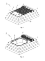
- a whirlpool 1 is shown with a basin 6 with inlet opening, which is delimited by a substantially horizontally extending whirlpool top edge 2.
- a cover element 3 can be pushed over the whirlpool top edge 2 in the transport direction 16 for completely covering or releasing the pelvis 6 or the inlet opening 7.
- FIG. 2 the basin 6 is fully released by the cover 3 is shown withdrawn into a base frame 4.
- the base frame 4 when the basin 6 is completely open, the base frame 4 can be lowered so far (in FIG Fig. 2 not shown) that an upper Edge or an upper cover of the base frame 4 with a bordering element 5 of the whirlpool 1 is flush with the surface.
- the entire cover device for the user can not be stowed apparent, which in particular also has the advantage that the view of the whirlpool users in any way is restricted, regardless of where the spa user is in the pool 6.
- the cover element 3 consists of lamellae, which - seen in the transport direction 16 - extend transversely and have the lateral end caps, which will be explained further below.
- the lamellae make it possible to flexibly form the cover element 3, so that it can be inserted into an, for example, spiral-shaped guide element with reduced frictional resistance or under the pelvic floor. Due to the structure of the cover 3 with lamellae increased strength is obtained perpendicular to the transport plane at the same time.
- Fig. 3 shows a base frame 4 for receiving a cover element 3 of slats with the elements contained therein in turn in a perspective view.
- a mobile contact strip 20 and a fixed contact strip 19 can be seen here. While the mobile contact strip 20 is arranged at the front end of the cover 3 and therefore moves with the cover 3, the fixed contact strip 19 on the base frame 4 above a feed opening for the Cover element 3 is arranged.
- Both the mobile and the fixed contact strip 20 and 19 are safety elements for the prevention of accidents and for machine protection (device protection) in an automatic operation of the inventive device.
- the contact strips 19, 20 are operatively connected to a control unit, so that when a triggering or response of the contact strips 19, 20 acting on the cover 3 drive unit (not shown) immediately stopped or the movement of the cover 3 can be reversed by reversing the direction of rotation ,
- a film unit 22 recognizable, which is arranged at the front end of the cover 3. Furthermore, a mobile contact strip 20 is provided on the film unit 22, with which any objects obstructing the inlet opening can be detected.
- the film unit 22 occupies the Whirlpooloberonkante 2 ( Fig. 1 or 2 ) with a film, which consists for example of a polymer before the cover 3 can touch the Whirlpooloberdeckkante 2 and the inlet opening. Consequently, the cover 3 is moved in the sequence on the spread film, which no scratches or other injuries of the Whirlpooloberseitekante 2 can arise. moreover causes the film an even better seal between the Whirlpooloberitkante 2 ( Fig. 1 or 2 ) and the cover 3.
- the film is also a high-quality, glass-fiber reinforced PTFE (polytetrafluoroethylene) excellently suitable, which is also known under the trade name TEFLON. It is important that the film is inherently stable, durable and at the same time sealing.
- PTFE polytetrafluoroethylene
- the film unit 22 comprises a first roller 23, on which the film is completely rolled up when the cover element 3 in the base frame 4 to release the pelvis 6 (FIG. Fig. 2 ) is recorded.
- On the roller 23 acts, for example, a preloaded coil spring (in Fig. 4 not shown), so that the film in each phase of a Abdeckvorganges without wrinkles spread or can be retracted again. Further variants of a film unit 22 will be explained below.
- a steel cable, a copper strand or another good electrically conductive material has the advantage that electrostatic charges, for example, when covering of the pelvis may arise due to friction between the cover element and the pelvic upper edge or due to friction of the film on at least one of the rollers, can be derived.
- FIG. 5 a hollow profile 51 for a lamella.
- An end cap 24 is shown, which - viewed in the transport direction 16 of the cover 3 - arranged laterally and inserted into a cavity of the cover 3 forming lamellae and is firmly connected to this.
- recesses (not visible) can be seen, which are arranged at a regular distance, wherein the recesses of adjacent end caps 24 are aligned, so that teeth of arranged on a drive shaft gears can engage in the recesses.
- the drive unit is thus operatively connected via the drive shaft, the gears and the end caps 24 with the cover 3. Accordingly, the cover 3 can be moved in one direction or the other depending on the direction of rotation of the drive unit.
- Fig. 5 1 shows an exploded view of a lateral end piece of a lamella 50 according to the invention.
- the lamella 50 in this example consists of a hollow profile 51, an end cap 24, as well as a seal 60 and a sealing ring 61, which in the assembled state, the hollow spaces of the hollow profile 51 with respect to the end cap 24 caulk.
- the hollow profile 51 has a number of special structures.
- a round profile 53 extends along the entire longitudinal axis of the hollow profile 51.
- a fitting profile 54 is formed on the opposite longitudinal axis of the hollow profile 51.
- the hollow profile 51 also has a substantially flat support surface 52 and opposite the support surface 52 two obliquely arranged surfaces, wherein a first surface 58 from the fitting profile 54 extends obliquely to the center and then merges into a second surface 59, which at a different angle to Support surface 52 extends as the first surface 58.
- the round profile 53 is connected via a web 57 with the rest of the hollow profile.
- the round profile 53 defines in its interior itself a cavity in which optionally a stabilizing tube can be installed.
- the hollow profile is produced for example by an extrusion process.
- strips 62 may be formed. These strips 62 are adapted to hold a flat profile in the hollow profile in position.
- Such a flat profile may extend over the entire length of the hollow profile and may be made of aluminum, for example.
- the flat profile serves to increase stability and strength.
- the cover 3 is designed cambered, so that water can drain laterally, especially on the end caps 24.
- a crowning of the cover 3 can be further reinforced or strengthened by the above-mentioned flat profile also has a crown.
- the seal ring 61 and the seal 60 are made of an elastic material such as rubber.
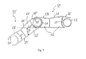
- FIG. 6 and 7 a partial section of a cover member 3 according to the invention is shown, wherein a section transverse to two mutually coupled hollow sections 51 and 51 'is shown, as already described with reference to Fig. 5 have been explained. Accordingly, in the Fig. 6 and 7 the flags used for the corresponding components in Fig. 5 have been introduced, wherein the hatched in the sectional area shown hollow profile 51 and not hatched in the cut surface hollow profile 51 'are constructed identically. The in the Fig. 6 and 7 shown and coupled together hollow sections 51 and 51 'are thereby rotated about the longitudinal axis of the round profile 53' and the fitting profile 54 against each other.
- the first hollow profile 51 is on the one hand from the round profile 53 and a leg 55 which is parallel to a surface formed from the longitudinal axis of the round profile 53 and the web 57.
- the fitting profile 54 on the opposite side, the fitting profile 54 on.
- a lower portion of the fitting profile 54 is formed in the present example on one side as an extension of the substantially flat support surface 52.
- An upper portion of the fitting profile 54 is formed from an extension of the first inclined surface 58.
- the first inclined surface 58 leads approximately to the middle of the hollow profile 51 and goes there in the second inclined surface 59 on.
- the thickness of the hollow profile 51, 51 ' is greater at the end provided with the round profile 53, 53' than at the end provided with the fitting profile 54, 54 '.
- the passport 54, 54 ' are dimensioned so that they can take a round profile 53, 53' and the hollow sections 51, 51 'in the manner mentioned can rotate against each other.
- the leg 55 'of the second hollow profile 51' is arranged so that it can slide over the fitting profile 54 of the first hollow profile 51.
- the web 57 'and the leg 55' of the second hollow profile 51 ' allow a rotational movement about an angle ⁇ about the longitudinal axis of the round profile 54, wherein the angle ⁇ is defined with respect to the support surface 52 of the first hollow profile 51 ( Fig. 6 ) and thus describes a convex shape of the cover. Therefore, the angle ⁇ is also referred to as a convex angle ⁇ . According to Fig.
- Fig. 7 shows Fig. 7 the other extreme for the rotational movement about the same axis, by now the other end of the fitting profile 54 on the other side of the Steges 57 'is pending.
- a maximum angle ⁇ 40 degrees is a maximum angle ⁇ 40 degrees.
- This maximum angle ⁇ has now, as is self-evident from the in the 3 and 4 shown construction, direct influence on the maximum radius of curvature for guide elements or guide rails for the cover 3.
- the angle ⁇ is hereinafter also referred to as a concave angle ⁇ , since it describes the concave configuration of the cover.
- the inventive cover 3 ( Fig. 1 ) consists of a plurality of interconnected hollow profiles 51, 51 '.
- the desired length for the cover 3 ( Fig. 1 ) correspondingly many hollow profiles to connect with each other.
- a copper strand - or another good electrically conductive material - has the advantage that electrostatic charges, which may arise, for example, when covering the pool by friction between the cover and the upper edge of the pool, can be derived.
- Fig. 8 shows a cover 3 in a view from below in a perspective view.
- the film unit 22 arranged in the transport direction 16 at the front end of the cover element 3 comprises a first roller 23 on which the film is wound, a smoothing roller 61 which ensures a smooth spreading of the film on the underside of the cover element 3, and a positioning roller 62 whose lowest point is flush with the underside of the cover 3.
- the foil itself is in Fig. 8 not apparent.
- the cover 3 according Fig. 8 consists in turn of interconnected slats 50, as discussed in detail in connection with the Fig. 5, 6 and 7 has been described.
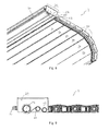
- Fig. 9 shows a part of the cover 3 together with the film unit 22 as in Fig. 8 however, in a side view with other components partially in Section are shown.
- the smoothing roller 61 and the positioning roller 62 have fixed positions and diameters.
- the smoothing roller 61 is offset because of their opposite rotational movement upwards, so that no additional frictional forces are generated on the upper edge edge of the basin.
- the positioning roller 62 is - as already mentioned - placed in the film unit 22, that the film after the deflection by the positioning roller 62 with the bottom of the cover 3 is flush.
- the first roller 23 is driven by moving the cover 3 or the film is pulled as needed by the first roller 23.
- the first roller 23 must be actively driven, so that the film can be wound reliably again on the first roller 23.
- This can be done, for example, by means of a drive which is controlled as a function of the speed of the cover element 3.
- the film unit 22 or the first roller 23 comprises a spring element, which is biased by a displacement when covering the manhole, so when opening the Boarding the film in turn can be rolled on the first roller 23.
- Fig. 10 shows a first roller 23 in a perspective view.
- the first roller 23 has at the end shown a mounting wheel 81 with holes 76 for fixed connection to a main support tube 72 on which the film can be wound up.
- a spring element is installed in the roller 23.
- Fig. 11 shows this in a step along the longitudinal axis through the first roller 23 according to Fig. 10 ,
- Fig. 11 shows the first roller 23 according to Fig. 10 in a section through the longitudinal axis of the roller 23, with hatching of the cut surfaces and fasteners such as set screws or the like are omitted.
- a spring element 70 is used for pretensioning the film.
- this embodiment comprises a planetary gear in order to use a stronger spring element 70 thanks to reduced rotational speed.
- the first roller 23 has at one end face a fastening wheel 81, with which a simple mounting on the housing of the film unit 22 (FIG. Fig. 9 ) is possible. Furthermore, bores 76 are provided in the fastening wheel 81. Through these holes 76 screws (in Fig. 11 Not shown) for fixed screwing with the spur gear 77 passed. As a result, the belonging to a transmission gear 71 spur gear 77 is fixed.
- a shaft 75 is guided by the mounting wheel 81 in the interior of the roller 23, wherein the shaft 75 is supported by bearings 74 in the mounting wheel 81 and in support bearings 73 of a centering 82 radially.
- the transmission gear 71 - comprising the spur gear 77, the planetary gears 78 and the sun gear 79 - is implemented in this embodiment as a so-called planetary gear or planetary gear (planetary).
- one end of the spring element 70 is fixed with a fastening 80 in the centering element 82.
- the other end of the spring element 70 is fixed with respect to the housing of the film unit 22.
- the spring element 70 when spreading the film, that is stretched during the covering process of the manhole, which due to a ratio of the transmission gear 71, the centering element 82 relative to the main support tube 72 rotates correspondingly slowed down.
- the main support tube 72 rotates three times around its own axis, while the centering element 82 rotates only once around its own axis.
- the spring element 70 three times less often turned up and therefore can be designed accordingly stronger.
- the embodiment of the invention is particularly suitable for covering large inlets excellent.
- cover elements of 6m length and more can be successfully covered with the film unit according to the invention.
- drives for controlled driving of the first roller can also be provided.
- the drives can be installed in the first pipe or arranged outside.
- a torque monitoring sensor may be used, which is connected to the control unit of the drive and ensures that a predefined constant tension acts on the foil.
- Fig. 12 shows in a perspective view of the base frame 4, wherein the view is released into the interior, so that a still to be explained helical guide element 12 can be seen.
- base frame 4 is a modular structure that structurally simple to Whirlpools of different construction and can be adapted by different manufacturers. It is conceivable, for example, a reduced design in which the base frame consists of a single, firmly connected to the whirlpool frame, in which case the various above-mentioned components are attached only to this one frame.
- Fig. 12 is the film unit 22 with the mobile contact strip 20 can be seen, in which case the cover 3 is completely retracted into the base frame 4, but at the same time only a short portion of the cover 3 is drawn.
- the height of the Whirlpoolobercoastkante 2 must match in the region of the outlet of the cover 3 with the guide member 12 such that the cover 3 can be pushed as possible without height offset on the Whirlpooloberhoskante 2 when the cover 3 for covering in the transport direction 16 (FIG. Fig. 1 ) is moved. Any necessary height adjustment can be accomplished by the use of feet with different dimensions and by fine adjustment of screw feet, which can be arranged below the feet.
- gears 9 are visible, which are operatively connected to the drive unit and which engage in an edge region in the cover 3 and its end caps. So that the cover 3 can be moved uniformly, gears 9 are provided on both sides, with opposing gears 9 are arranged on a shaft.
- the spiral guide elements 12 connected to the base frame 4 support the cover element 3 from the side in the direction of transport 16.
- three guide rails 13, 14 and 15 are provided, which defines the freedom of movement of the cover 3 in the region of the base frame 4 defined, so that only the cover 3 here remains a one-dimensional movement possibility.
- a first guide rail 13 above the cover 3 In the region of an outlet opening, in which the cover element 3 leaves the base frame 4 and from then on the whirlpool top edge edge 2 (FIG. Fig. 1 and 2 ), a first guide rail 13 above the cover 3, a second guide rail 14 laterally in the transport direction 16 of the cover 3 and a third guide rail 15 below the cover 3 seen arranged laterally.
- the guide rails 13, 14 and 15 have, for example, a round cross-section.
- any desired shape for the guide elements 12 can be provided.
- a helical guide element 12, as shown in the illustrated embodiment of the invention, has proven to be advantageous when a space-saving variant is preferred.
- spiral shapes with a rectangular basic shape may also be suitable, since in this way the available space, which is due to a base frame with a cross section corresponding to a raised rectangle, can be optimally exploited.
- the base frame 4 in a modularly expandable manner.
- the base frame 4 are divided into an upper and a lower part, so that an expansion module 90 or more extension modules 90 to 92 can be inserted therebetween.
- the expansion modules 90 to 92 are designed so that the guide rails 13, 14 and 15 can be seamlessly connected to the corresponding guide rails of the upper and lower part. It is also conceivable and advantageous for proper transporting of the cover element 3 in the area of the expansion modules 90 to 92 that the expansion modules 90 to 92 also have toothed wheels 9 for transporting the cover element 3. This is provided, for example, in the extension modules 91 and 92 as it is Fig. 12 is apparent.
- Fig. 13 again shows a perspective view of another embodiment for a Inventive device for covering a manhole.
- the base frame 4 is designed to be relatively slim in this embodiment, since the cover 3 is now not performed in a helical guide element, but it is the cover 3 through the base frame 4 and then passed under the basin.
- a support structure 100 is provided, in which the cover 3 can be introduced.
- the support structure must be stably designed to accommodate the weight of the pool.
- the base frame 4 can be constructed according to modular, so that the base frame 4 can be easily adapted to different pelvic depths.
Landscapes
- Engineering & Computer Science (AREA)
- Architecture (AREA)
- Civil Engineering (AREA)
- Structural Engineering (AREA)
- Underground Structures, Protecting, Testing And Restoring Foundations (AREA)
- Lining Or Joining Of Plastics Or The Like (AREA)
- Devices For Medical Bathing And Washing (AREA)
- Operating, Guiding And Securing Of Roll- Type Closing Members (AREA)
Applications Claiming Priority (1)
| Application Number | Priority Date | Filing Date | Title |
|---|---|---|---|
| CH01641/12A CH706945A2 (de) | 2012-09-10 | 2012-09-10 | Vorrichtung zur Abdeckung einer Einstiegsöffnung bei einem Whirlpool. |
Publications (3)
| Publication Number | Publication Date |
|---|---|
| EP2706169A2 true EP2706169A2 (fr) | 2014-03-12 |
| EP2706169A3 EP2706169A3 (fr) | 2017-10-18 |
| EP2706169B1 EP2706169B1 (fr) | 2018-11-07 |
Family
ID=49118290
Family Applications (1)
| Application Number | Title | Priority Date | Filing Date |
|---|---|---|---|
| EP13181239.8A Not-in-force EP2706169B1 (fr) | 2012-09-10 | 2013-08-21 | Dispositif destiné au recouvrement d'une ouverture d'entrée dans une baignoire de balnéothérapie |
Country Status (2)
| Country | Link |
|---|---|
| EP (1) | EP2706169B1 (fr) |
| CH (1) | CH706945A2 (fr) |
Cited By (1)
| Publication number | Priority date | Publication date | Assignee | Title |
|---|---|---|---|---|
| IT202200002564A1 (it) * | 2022-02-11 | 2023-08-11 | Free Plast Srl | Sistema di rivestimento piscine |
Citations (2)
| Publication number | Priority date | Publication date | Assignee | Title |
|---|---|---|---|---|
| US6000072A (en) | 1998-09-09 | 1999-12-14 | Lahay; Leon | Spa cover remover |
| EP2028333A2 (fr) | 2007-08-24 | 2009-02-25 | Pionier PAMAG | Couvercle pour bain à remous |
Family Cites Families (3)
| Publication number | Priority date | Publication date | Assignee | Title |
|---|---|---|---|---|
| US3574979A (en) * | 1969-06-06 | 1971-04-13 | John Y S Chan | Inflatable cover |
| FR2719863B1 (fr) * | 1994-05-10 | 1996-08-23 | Lamort Pierre | Dispositif enrouleur-dérouleur d'un rideau semi-rigide destiné à couvrir une piscine. |
| FR2929309B1 (fr) * | 2008-03-28 | 2016-07-01 | Dsn Design Service Network | Dispositif d'entrainement d'un volet de couverture de piscine |
-
2012
- 2012-09-10 CH CH01641/12A patent/CH706945A2/de not_active Application Discontinuation
-
2013
- 2013-08-21 EP EP13181239.8A patent/EP2706169B1/fr not_active Not-in-force
Patent Citations (2)
| Publication number | Priority date | Publication date | Assignee | Title |
|---|---|---|---|---|
| US6000072A (en) | 1998-09-09 | 1999-12-14 | Lahay; Leon | Spa cover remover |
| EP2028333A2 (fr) | 2007-08-24 | 2009-02-25 | Pionier PAMAG | Couvercle pour bain à remous |
Cited By (2)
| Publication number | Priority date | Publication date | Assignee | Title |
|---|---|---|---|---|
| IT202200002564A1 (it) * | 2022-02-11 | 2023-08-11 | Free Plast Srl | Sistema di rivestimento piscine |
| WO2023152718A1 (fr) * | 2022-02-11 | 2023-08-17 | Free Plast Srl | Système de revêtement externe pour piscines hors-sol ou semi-enterrées |
Also Published As
| Publication number | Publication date |
|---|---|
| EP2706169B1 (fr) | 2018-11-07 |
| CH706945A2 (de) | 2014-03-14 |
| EP2706169A3 (fr) | 2017-10-18 |
Similar Documents
| Publication | Publication Date | Title |
|---|---|---|
| DE69723114T2 (de) | Rolltor mit reibungsarmen randbereichen | |
| DE69731668T2 (de) | Bedienungsstab für bedeckungen von gebäudeöffnungen | |
| DE2317086A1 (de) | Vorrichtung zur erzeugung eines luftvorhangs | |
| EP0982466B1 (fr) | Store à rouleau | |
| WO2019034323A1 (fr) | Porte, notamment porte á spirale | |
| EP2497876A2 (fr) | Dispositif de recouvrement d'un jacuzzi | |
| EP2706169B1 (fr) | Dispositif destiné au recouvrement d'une ouverture d'entrée dans une baignoire de balnéothérapie | |
| DE2049365A1 (fr) | ||
| DE3344359A1 (de) | Fenstermarkise | |
| DE4038419A1 (de) | Vorrichtung zum auf- und abrollen eines wickelbaren behanges fuer baukoerper, insbesondere zum witterungs- und sonnenschutz | |
| DE69211108T2 (de) | Starre Abdeckungsvorrichtung für Schwimmbäder und Becken | |
| DE2419546A1 (de) | Schrank mit mindestens einem herausziehbaren teil | |
| DE19805272B4 (de) | Einrichtung zum Schützen, Abdecken, Verschließen, Abtrennen o. dgl. Abgrenzen von Bereichen | |
| AT4379U1 (de) | Abdeckung für schwimmbecken od.dgl. | |
| AT14965U1 (de) | Abdeckvorrichtung für ein becken | |
| WO2000061896A1 (fr) | Element de recouvrement pour piscines ou similaires | |
| DE2524848A1 (de) | Vorrichtung zum abdecken von schwimmbecken | |
| AT308344B (de) | Aufrollbare Abdeckung für mit Flüssigkeit gefüllte Becken, insbesondere für Schwimmbecken | |
| DE102013110488B4 (de) | Verschiebbare Spritzschutzwand | |
| EP2090736B1 (fr) | Store | |
| DE29824480U1 (de) | Wickeljalousie | |
| DE2845411A1 (de) | Vorrichtung zum abdecken von becken, insbesondere von schwimmbecken | |
| EP1203859B1 (fr) | Couverture de bassin de natation | |
| DE3523476A1 (de) | Schwimmbadabdeckung | |
| DE7835359U1 (de) | Rolladenvorrichtung |
Legal Events
| Date | Code | Title | Description |
|---|---|---|---|
| PUAI | Public reference made under article 153(3) epc to a published international application that has entered the european phase |
Free format text: ORIGINAL CODE: 0009012 |
|
| AK | Designated contracting states |
Kind code of ref document: A2 Designated state(s): AL AT BE BG CH CY CZ DE DK EE ES FI FR GB GR HR HU IE IS IT LI LT LU LV MC MK MT NL NO PL PT RO RS SE SI SK SM TR |
|
| AX | Request for extension of the european patent |
Extension state: BA ME |
|
| PUAL | Search report despatched |
Free format text: ORIGINAL CODE: 0009013 |
|
| AK | Designated contracting states |
Kind code of ref document: A3 Designated state(s): AL AT BE BG CH CY CZ DE DK EE ES FI FR GB GR HR HU IE IS IT LI LT LU LV MC MK MT NL NO PL PT RO RS SE SI SK SM TR |
|
| AX | Request for extension of the european patent |
Extension state: BA ME |
|
| RIC1 | Information provided on ipc code assigned before grant |
Ipc: A61H 33/00 20060101ALI20170913BHEP Ipc: E04H 4/08 20060101AFI20170913BHEP |
|
| STAA | Information on the status of an ep patent application or granted ep patent |
Free format text: STATUS: REQUEST FOR EXAMINATION WAS MADE |
|
| 17P | Request for examination filed |
Effective date: 20180306 |
|
| RBV | Designated contracting states (corrected) |
Designated state(s): AL AT BE BG CH CY CZ DE DK EE ES FI FR GB GR HR HU IE IS IT LI LT LU LV MC MK MT NL NO PL PT RO RS SE SI SK SM TR |
|
| GRAP | Despatch of communication of intention to grant a patent |
Free format text: ORIGINAL CODE: EPIDOSNIGR1 |
|
| STAA | Information on the status of an ep patent application or granted ep patent |
Free format text: STATUS: GRANT OF PATENT IS INTENDED |
|
| INTG | Intention to grant announced |
Effective date: 20180601 |
|
| GRAS | Grant fee paid |
Free format text: ORIGINAL CODE: EPIDOSNIGR3 |
|
| GRAA | (expected) grant |
Free format text: ORIGINAL CODE: 0009210 |
|
| STAA | Information on the status of an ep patent application or granted ep patent |
Free format text: STATUS: THE PATENT HAS BEEN GRANTED |
|
| AK | Designated contracting states |
Kind code of ref document: B1 Designated state(s): AL AT BE BG CH CY CZ DE DK EE ES FI FR GB GR HR HU IE IS IT LI LT LU LV MC MK MT NL NO PL PT RO RS SE SI SK SM TR |
|
| REG | Reference to a national code |
Ref country code: GB Ref legal event code: FG4D Free format text: NOT ENGLISH |
|
| REG | Reference to a national code |
Ref country code: CH Ref legal event code: EP Ref country code: AT Ref legal event code: REF Ref document number: 1062215 Country of ref document: AT Kind code of ref document: T Effective date: 20181115 |
|
| REG | Reference to a national code |
Ref country code: IE Ref legal event code: FG4D Free format text: LANGUAGE OF EP DOCUMENT: GERMAN |
|
| REG | Reference to a national code |
Ref country code: DE Ref legal event code: R096 Ref document number: 502013011525 Country of ref document: DE |
|
| REG | Reference to a national code |
Ref country code: CH Ref legal event code: NV Representative=s name: TROESCH SCHEIDEGGER WERNER AG, CH |
|
| REG | Reference to a national code |
Ref country code: NL Ref legal event code: MP Effective date: 20181107 |
|
| REG | Reference to a national code |
Ref country code: LT Ref legal event code: MG4D |
|
| PG25 | Lapsed in a contracting state [announced via postgrant information from national office to epo] |
Ref country code: BG Free format text: LAPSE BECAUSE OF FAILURE TO SUBMIT A TRANSLATION OF THE DESCRIPTION OR TO PAY THE FEE WITHIN THE PRESCRIBED TIME-LIMIT Effective date: 20190207 Ref country code: HR Free format text: LAPSE BECAUSE OF FAILURE TO SUBMIT A TRANSLATION OF THE DESCRIPTION OR TO PAY THE FEE WITHIN THE PRESCRIBED TIME-LIMIT Effective date: 20181107 Ref country code: ES Free format text: LAPSE BECAUSE OF FAILURE TO SUBMIT A TRANSLATION OF THE DESCRIPTION OR TO PAY THE FEE WITHIN THE PRESCRIBED TIME-LIMIT Effective date: 20181107 Ref country code: NO Free format text: LAPSE BECAUSE OF FAILURE TO SUBMIT A TRANSLATION OF THE DESCRIPTION OR TO PAY THE FEE WITHIN THE PRESCRIBED TIME-LIMIT Effective date: 20190207 Ref country code: LT Free format text: LAPSE BECAUSE OF FAILURE TO SUBMIT A TRANSLATION OF THE DESCRIPTION OR TO PAY THE FEE WITHIN THE PRESCRIBED TIME-LIMIT Effective date: 20181107 Ref country code: IS Free format text: LAPSE BECAUSE OF FAILURE TO SUBMIT A TRANSLATION OF THE DESCRIPTION OR TO PAY THE FEE WITHIN THE PRESCRIBED TIME-LIMIT Effective date: 20190307 Ref country code: FI Free format text: LAPSE BECAUSE OF FAILURE TO SUBMIT A TRANSLATION OF THE DESCRIPTION OR TO PAY THE FEE WITHIN THE PRESCRIBED TIME-LIMIT Effective date: 20181107 Ref country code: LV Free format text: LAPSE BECAUSE OF FAILURE TO SUBMIT A TRANSLATION OF THE DESCRIPTION OR TO PAY THE FEE WITHIN THE PRESCRIBED TIME-LIMIT Effective date: 20181107 |
|
| PG25 | Lapsed in a contracting state [announced via postgrant information from national office to epo] |
Ref country code: GR Free format text: LAPSE BECAUSE OF FAILURE TO SUBMIT A TRANSLATION OF THE DESCRIPTION OR TO PAY THE FEE WITHIN THE PRESCRIBED TIME-LIMIT Effective date: 20190208 Ref country code: RS Free format text: LAPSE BECAUSE OF FAILURE TO SUBMIT A TRANSLATION OF THE DESCRIPTION OR TO PAY THE FEE WITHIN THE PRESCRIBED TIME-LIMIT Effective date: 20181107 Ref country code: SE Free format text: LAPSE BECAUSE OF FAILURE TO SUBMIT A TRANSLATION OF THE DESCRIPTION OR TO PAY THE FEE WITHIN THE PRESCRIBED TIME-LIMIT Effective date: 20181107 Ref country code: AL Free format text: LAPSE BECAUSE OF FAILURE TO SUBMIT A TRANSLATION OF THE DESCRIPTION OR TO PAY THE FEE WITHIN THE PRESCRIBED TIME-LIMIT Effective date: 20181107 Ref country code: PT Free format text: LAPSE BECAUSE OF FAILURE TO SUBMIT A TRANSLATION OF THE DESCRIPTION OR TO PAY THE FEE WITHIN THE PRESCRIBED TIME-LIMIT Effective date: 20190307 Ref country code: NL Free format text: LAPSE BECAUSE OF FAILURE TO SUBMIT A TRANSLATION OF THE DESCRIPTION OR TO PAY THE FEE WITHIN THE PRESCRIBED TIME-LIMIT Effective date: 20181107 |
|
| PG25 | Lapsed in a contracting state [announced via postgrant information from national office to epo] |
Ref country code: DK Free format text: LAPSE BECAUSE OF FAILURE TO SUBMIT A TRANSLATION OF THE DESCRIPTION OR TO PAY THE FEE WITHIN THE PRESCRIBED TIME-LIMIT Effective date: 20181107 Ref country code: PL Free format text: LAPSE BECAUSE OF FAILURE TO SUBMIT A TRANSLATION OF THE DESCRIPTION OR TO PAY THE FEE WITHIN THE PRESCRIBED TIME-LIMIT Effective date: 20181107 Ref country code: IT Free format text: LAPSE BECAUSE OF FAILURE TO SUBMIT A TRANSLATION OF THE DESCRIPTION OR TO PAY THE FEE WITHIN THE PRESCRIBED TIME-LIMIT Effective date: 20181107 Ref country code: CZ Free format text: LAPSE BECAUSE OF FAILURE TO SUBMIT A TRANSLATION OF THE DESCRIPTION OR TO PAY THE FEE WITHIN THE PRESCRIBED TIME-LIMIT Effective date: 20181107 |
|
| REG | Reference to a national code |
Ref country code: DE Ref legal event code: R097 Ref document number: 502013011525 Country of ref document: DE |
|
| PG25 | Lapsed in a contracting state [announced via postgrant information from national office to epo] |
Ref country code: RO Free format text: LAPSE BECAUSE OF FAILURE TO SUBMIT A TRANSLATION OF THE DESCRIPTION OR TO PAY THE FEE WITHIN THE PRESCRIBED TIME-LIMIT Effective date: 20181107 Ref country code: EE Free format text: LAPSE BECAUSE OF FAILURE TO SUBMIT A TRANSLATION OF THE DESCRIPTION OR TO PAY THE FEE WITHIN THE PRESCRIBED TIME-LIMIT Effective date: 20181107 Ref country code: SM Free format text: LAPSE BECAUSE OF FAILURE TO SUBMIT A TRANSLATION OF THE DESCRIPTION OR TO PAY THE FEE WITHIN THE PRESCRIBED TIME-LIMIT Effective date: 20181107 Ref country code: SK Free format text: LAPSE BECAUSE OF FAILURE TO SUBMIT A TRANSLATION OF THE DESCRIPTION OR TO PAY THE FEE WITHIN THE PRESCRIBED TIME-LIMIT Effective date: 20181107 |
|
| PLBE | No opposition filed within time limit |
Free format text: ORIGINAL CODE: 0009261 |
|
| STAA | Information on the status of an ep patent application or granted ep patent |
Free format text: STATUS: NO OPPOSITION FILED WITHIN TIME LIMIT |
|
| 26N | No opposition filed |
Effective date: 20190808 |
|
| PG25 | Lapsed in a contracting state [announced via postgrant information from national office to epo] |
Ref country code: SI Free format text: LAPSE BECAUSE OF FAILURE TO SUBMIT A TRANSLATION OF THE DESCRIPTION OR TO PAY THE FEE WITHIN THE PRESCRIBED TIME-LIMIT Effective date: 20181107 |
|
| REG | Reference to a national code |
Ref country code: DE Ref legal event code: R119 Ref document number: 502013011525 Country of ref document: DE |
|
| PG25 | Lapsed in a contracting state [announced via postgrant information from national office to epo] |
Ref country code: TR Free format text: LAPSE BECAUSE OF FAILURE TO SUBMIT A TRANSLATION OF THE DESCRIPTION OR TO PAY THE FEE WITHIN THE PRESCRIBED TIME-LIMIT Effective date: 20181107 |
|
| GBPC | Gb: european patent ceased through non-payment of renewal fee |
Effective date: 20190821 |
|
| PG25 | Lapsed in a contracting state [announced via postgrant information from national office to epo] |
Ref country code: CH Free format text: LAPSE BECAUSE OF NON-PAYMENT OF DUE FEES Effective date: 20190831 Ref country code: MC Free format text: LAPSE BECAUSE OF FAILURE TO SUBMIT A TRANSLATION OF THE DESCRIPTION OR TO PAY THE FEE WITHIN THE PRESCRIBED TIME-LIMIT Effective date: 20181107 Ref country code: LU Free format text: LAPSE BECAUSE OF NON-PAYMENT OF DUE FEES Effective date: 20190821 Ref country code: LI Free format text: LAPSE BECAUSE OF NON-PAYMENT OF DUE FEES Effective date: 20190831 |
|
| REG | Reference to a national code |
Ref country code: BE Ref legal event code: MM Effective date: 20190831 |
|
| PG25 | Lapsed in a contracting state [announced via postgrant information from national office to epo] |
Ref country code: FR Free format text: LAPSE BECAUSE OF NON-PAYMENT OF DUE FEES Effective date: 20190831 Ref country code: IE Free format text: LAPSE BECAUSE OF NON-PAYMENT OF DUE FEES Effective date: 20190821 Ref country code: DE Free format text: LAPSE BECAUSE OF NON-PAYMENT OF DUE FEES Effective date: 20200303 |
|
| PG25 | Lapsed in a contracting state [announced via postgrant information from national office to epo] |
Ref country code: GB Free format text: LAPSE BECAUSE OF NON-PAYMENT OF DUE FEES Effective date: 20190821 Ref country code: BE Free format text: LAPSE BECAUSE OF NON-PAYMENT OF DUE FEES Effective date: 20190831 |
|
| REG | Reference to a national code |
Ref country code: AT Ref legal event code: MM01 Ref document number: 1062215 Country of ref document: AT Kind code of ref document: T Effective date: 20190821 |
|
| PG25 | Lapsed in a contracting state [announced via postgrant information from national office to epo] |
Ref country code: AT Free format text: LAPSE BECAUSE OF NON-PAYMENT OF DUE FEES Effective date: 20190821 |
|
| PG25 | Lapsed in a contracting state [announced via postgrant information from national office to epo] |
Ref country code: CY Free format text: LAPSE BECAUSE OF FAILURE TO SUBMIT A TRANSLATION OF THE DESCRIPTION OR TO PAY THE FEE WITHIN THE PRESCRIBED TIME-LIMIT Effective date: 20181107 |
|
| PG25 | Lapsed in a contracting state [announced via postgrant information from national office to epo] |
Ref country code: HU Free format text: LAPSE BECAUSE OF FAILURE TO SUBMIT A TRANSLATION OF THE DESCRIPTION OR TO PAY THE FEE WITHIN THE PRESCRIBED TIME-LIMIT; INVALID AB INITIO Effective date: 20130821 Ref country code: MT Free format text: LAPSE BECAUSE OF FAILURE TO SUBMIT A TRANSLATION OF THE DESCRIPTION OR TO PAY THE FEE WITHIN THE PRESCRIBED TIME-LIMIT Effective date: 20181107 |
|
| PG25 | Lapsed in a contracting state [announced via postgrant information from national office to epo] |
Ref country code: MK Free format text: LAPSE BECAUSE OF FAILURE TO SUBMIT A TRANSLATION OF THE DESCRIPTION OR TO PAY THE FEE WITHIN THE PRESCRIBED TIME-LIMIT Effective date: 20181107 |