EP2706193A2 - Support de grille - Google Patents
Support de grille Download PDFInfo
- Publication number
- EP2706193A2 EP2706193A2 EP13181143.2A EP13181143A EP2706193A2 EP 2706193 A2 EP2706193 A2 EP 2706193A2 EP 13181143 A EP13181143 A EP 13181143A EP 2706193 A2 EP2706193 A2 EP 2706193A2
- Authority
- EP
- European Patent Office
- Prior art keywords
- lattice girder
- loops
- metal strips
- lattice
- lower chords
- Prior art date
- Legal status (The legal status is an assumption and is not a legal conclusion. Google has not performed a legal analysis and makes no representation as to the accuracy of the status listed.)
- Withdrawn
Links
Images


Classifications
-
- E—FIXED CONSTRUCTIONS
- E04—BUILDING
- E04C—STRUCTURAL ELEMENTS; BUILDING MATERIALS
- E04C5/00—Reinforcing elements, e.g. for concrete; Auxiliary elements therefor
- E04C5/01—Reinforcing elements of metal, e.g. with non-structural coatings
- E04C5/06—Reinforcing elements of metal, e.g. with non-structural coatings of high bending resistance, i.e. of essentially three-dimensional [3D] extent, e.g. lattice girders
-
- E—FIXED CONSTRUCTIONS
- E21—EARTH OR ROCK DRILLING; MINING
- E21D—SHAFTS; TUNNELS; GALLERIES; LARGE UNDERGROUND CHAMBERS
- E21D11/00—Lining tunnels, galleries or other underground cavities, e.g. large underground chambers; Linings therefor; Making such linings in situ, e.g. by assembling
- E21D11/04—Lining with building materials
- E21D11/10—Lining with building materials with concrete cast in situ; Shuttering also lost shutterings, e.g. made of blocks, of metal plates or other equipment adapted therefor
- E21D11/107—Reinforcing elements therefor; Holders for the reinforcing elements
-
- E—FIXED CONSTRUCTIONS
- E04—BUILDING
- E04C—STRUCTURAL ELEMENTS; BUILDING MATERIALS
- E04C3/00—Structural elongated elements designed for load-supporting
- E04C3/02—Joists; Girders, trusses, or trusslike structures, e.g. prefabricated; Lintels; Transoms; Braces
- E04C3/04—Joists; Girders, trusses, or trusslike structures, e.g. prefabricated; Lintels; Transoms; Braces of metal
- E04C3/08—Joists; Girders, trusses, or trusslike structures, e.g. prefabricated; Lintels; Transoms; Braces of metal with apertured web, e.g. with a web consisting of bar-like components; Honeycomb girders
-
- E—FIXED CONSTRUCTIONS
- E04—BUILDING
- E04C—STRUCTURAL ELEMENTS; BUILDING MATERIALS
- E04C5/00—Reinforcing elements, e.g. for concrete; Auxiliary elements therefor
- E04C5/16—Auxiliary parts for reinforcements, e.g. connectors, spacers, stirrups
- E04C5/162—Connectors or means for connecting parts for reinforcements
- E04C5/163—Connectors or means for connecting parts for reinforcements the reinforcements running in one single direction
-
- E—FIXED CONSTRUCTIONS
- E04—BUILDING
- E04C—STRUCTURAL ELEMENTS; BUILDING MATERIALS
- E04C3/00—Structural elongated elements designed for load-supporting
- E04C3/02—Joists; Girders, trusses, or trusslike structures, e.g. prefabricated; Lintels; Transoms; Braces
- E04C3/04—Joists; Girders, trusses, or trusslike structures, e.g. prefabricated; Lintels; Transoms; Braces of metal
- E04C2003/0404—Joists; Girders, trusses, or trusslike structures, e.g. prefabricated; Lintels; Transoms; Braces of metal beams, girders, or joists characterised by cross-sectional aspects
- E04C2003/0408—Joists; Girders, trusses, or trusslike structures, e.g. prefabricated; Lintels; Transoms; Braces of metal beams, girders, or joists characterised by cross-sectional aspects characterised by assembly or the cross-section
- E04C2003/0413—Joists; Girders, trusses, or trusslike structures, e.g. prefabricated; Lintels; Transoms; Braces of metal beams, girders, or joists characterised by cross-sectional aspects characterised by assembly or the cross-section being built up from several parts
-
- E—FIXED CONSTRUCTIONS
- E04—BUILDING
- E04C—STRUCTURAL ELEMENTS; BUILDING MATERIALS
- E04C3/00—Structural elongated elements designed for load-supporting
- E04C3/02—Joists; Girders, trusses, or trusslike structures, e.g. prefabricated; Lintels; Transoms; Braces
- E04C3/04—Joists; Girders, trusses, or trusslike structures, e.g. prefabricated; Lintels; Transoms; Braces of metal
- E04C2003/0404—Joists; Girders, trusses, or trusslike structures, e.g. prefabricated; Lintels; Transoms; Braces of metal beams, girders, or joists characterised by cross-sectional aspects
- E04C2003/0443—Joists; Girders, trusses, or trusslike structures, e.g. prefabricated; Lintels; Transoms; Braces of metal beams, girders, or joists characterised by cross-sectional aspects characterised by substantial shape of the cross-section
- E04C2003/0469—Joists; Girders, trusses, or trusslike structures, e.g. prefabricated; Lintels; Transoms; Braces of metal beams, girders, or joists characterised by cross-sectional aspects characterised by substantial shape of the cross-section triangular-shaped
-
- E—FIXED CONSTRUCTIONS
- E04—BUILDING
- E04C—STRUCTURAL ELEMENTS; BUILDING MATERIALS
- E04C3/00—Structural elongated elements designed for load-supporting
- E04C3/02—Joists; Girders, trusses, or trusslike structures, e.g. prefabricated; Lintels; Transoms; Braces
- E04C3/04—Joists; Girders, trusses, or trusslike structures, e.g. prefabricated; Lintels; Transoms; Braces of metal
- E04C2003/0486—Truss like structures composed of separate truss elements
- E04C2003/0495—Truss like structures composed of separate truss elements the truss elements being located in several non-parallel surfaces
-
- E—FIXED CONSTRUCTIONS
- E04—BUILDING
- E04C—STRUCTURAL ELEMENTS; BUILDING MATERIALS
- E04C3/00—Structural elongated elements designed for load-supporting
- E04C3/02—Joists; Girders, trusses, or trusslike structures, e.g. prefabricated; Lintels; Transoms; Braces
-
- E—FIXED CONSTRUCTIONS
- E04—BUILDING
- E04C—STRUCTURAL ELEMENTS; BUILDING MATERIALS
- E04C3/00—Structural elongated elements designed for load-supporting
- E04C3/30—Columns; Pillars; Struts
-
- E—FIXED CONSTRUCTIONS
- E04—BUILDING
- E04C—STRUCTURAL ELEMENTS; BUILDING MATERIALS
- E04C5/00—Reinforcing elements, e.g. for concrete; Auxiliary elements therefor
- E04C5/16—Auxiliary parts for reinforcements, e.g. connectors, spacers, stirrups
- E04C5/162—Connectors or means for connecting parts for reinforcements
- E04C5/163—Connectors or means for connecting parts for reinforcements the reinforcements running in one single direction
- E04C5/165—Coaxial connection by means of sleeves
Definitions
- the invention relates to a lattice girder for the expansion of tunnel-shaped structures according to the features in the preamble of claim 1.
- the vault obtained during excavation in the construction of underground structures requires direct support to secure it.
- carrier frames adapted to the respective breakout geometry are used.
- the individual support frames remain within the same by the concrete shell is created in Ortbetonweise using shotcrete.
- metal lattice girders in the form of a truss structure have proven themselves. Their advantage lies in both the material and weight savings as well as in the prevention of unwanted voids by the otherwise occurring in solid wall profiles Spray shadows.
- the individual lattice girders are only assembled on site to form a lattice arch lined up in the circumferential direction of the expansion, which, thanks to its open structure, enables a homogeneous construction of the concrete shell.
- the individual lattice girders achieve a high bond quality with the concrete shell, in which they serve as additional reinforcement in addition to the use of welded mesh.
- the DE 20 2010 004 389 U1 discloses a lattice girder for the construction of tunnel-shaped structures.
- the lattice girder each has a top chord and two bottom chords which extend together in the longitudinal direction of the lattice girder. Here, they form the vertices of a triangle in the cross section of the lattice girder to each other.
- the upper belt is connected via a truss arrangement of individual struts with the individual lower chords.
- coupling elements are provided at its ends.
- the interlinked with the straps coupling elements have openings, which can be brought together when connecting two lattice girders on top of each other. The actual coupling takes place via inserted into the openings and this interspersing connection means.
- the individual lattice girders can be transported to save space, since the actual grid sheet is mounted only at its respective place of use. Both the storage and the transport, the individual lattice girders are stacked such that in each case a lattice girder is placed with its upper flange between the lower chords of another lattice girder. Due to the necessary configuration of the curved lattice girders with coupling elements, stackability is currently only possible for those whose upper girder faces the mountains. In conventionally curved lattice girders, the two lower straps facing the mountains, a stackability is only given if they are initially performed without coupling elements and transported to their place of use.
- the prior art also includes a lattice girder as in the DE 81 25 375 U1 described.
- the invention is based on the object to improve a lattice girder as described above for the expansion of tunnel-shaped structures to the effect that this has already provided ex works for connection to other lattice girder coupling elements, which allow economic stackability of multiple lattice girders.
- the coupling elements located at the two ends of the lattice girder comprise in each case two sheet metal strips which extend from the top chord to one of the bottom chords in each case.
- the metal strips also have end arranged loops, which are provided for receiving connecting means.
- the advantage of the inventive design of the coupling elements is the fact that the initially flat design in the form of sheet metal strips in combination with end loops outer dimensions at the ends of the lattice girder brings with it, which allows the lattice girder when stacking in the open Area of another lattice girder fits into it.
- the stackability is made possible in that in particular no perpendicular to the straps extending webs are present, which occur when stacking several lattice girder in an immediate contact with the lower chords of the adjacent carrier. Due to the flat arrangement of the metal strips on the straps, the coupling elements are already significantly reduced in their outer dimensions.
- the end loops, which are arranged in the region of the upper and lower straps, have enough free space between them, in which the lower straps of an adjacent lattice girder can dip.
- the stacked lattice girders can be inserted significantly deeper into each other, so that the number of lattice girders to be stacked is increased.
- Both the upper and lower chords may have different cross-sectional shapes, such as square, rectangular, and oval, or combinations of the foregoing.
- these are circular, to allow easy production.
- the lateral surface of the individual straps can also be given a structure, such as, for example, ribbed or profiled reinforcing steel. This increases the composite effect of the lattice girder with the concrete surrounding it.
- the end of the metal strip arranged loops can be formed for example by sleeves, which are joined to the metal strips.
- the length of the loops can basically be based on the width of the metal strips extending in the longitudinal direction of the lattice girder.
- the length of the loops compared to the width of the metal strip may be smaller, so that, for example, the head of an inserted into the loop connecting means is flush with the metal strip.
- the individual loops can be formed from a respective bent end portion of the sheet metal strip.
- the position of the loops can be determined solely by the bending process. In addition to the respective position thus the required inner diameter for receiving corresponding connecting means can thus be easily adjusted without vorzuhalten a variety of different sized sleeves.
- the metal strips may have individual bends.
- the bends are arranged in the region of the loops. Due to the bending of the sheet metal strip in particular the position of the loop against the straps is adjustable.
- the fold can also be designed so that the loop is as close as possible to one of the straps or the metal strip itself.
- the fold can be designed so that the respective sheet-metal strip on the fold has a line contact with the upper flange and / or the lower chords, in the region of a corresponding weld joint can be attached.
- the two lower straps mentally tension a ground plane between them, wherein the loops located in the region of the upper belt, each of a coupling element, and the upper belt lie on the circumference of a plane extending parallel to this basic plane.
- the advantage here is to be seen in a footprint thus generated, which provides the individual lattice girder when placed on a substrate with its upper flange a corresponding grip and minimizes the risk of tipping.
- At least one transverse web can be arranged between two struts of the truss arrangement, which extend from the top chord to one of the bottom chords.
- the individual transverse web extends between two struts and is advantageously arranged at a distance from the upper flange and at a corresponding distance from the lower chords.
- the particular advantage lies in the contactless spacing of the transverse webs of the individual straps, whereby the triangular shape formed in the cross section of the lattice girder is reduced. This is achieved by shifting the individual transverse webs as the base of the triangle away from the lower belts and thus towards the upper belt. This results in a free space which extends between the lower chords to below the transverse webs.
- the cross section of the lattice girder formed by the truss struts and the transverse webs thus substantially resembles an A-shape.
- the distance to the upper flange and the distance to the lower chords have a ratio of 1: 2 to 1: 6 to each other.
- In an arrangement of the transverse webs within the indicated area results in an economic ratio of achieved by the transverse webs bending stiffness of the truss struts to the gained space between the lower chords.
- transverse webs on the lattice girder may have identical or different configurations from one another.
- a straight course of the individual cross bar can for example also be bent or folded and have individual formations or cross-sectional jumps.
- the transverse web has a curved course.
- the curved transverse web is open to the lower chords.
- the advantage consists in the joints of the transverse web with the struts which are thus located as close as possible to the lower chords, whereas the middle section of the transverse web is displaced as far as possible to the upper chord.
- a sufficiently large space between the legs formed by the struts of the lattice girder is created to achieve a deep immersion of another lattice girder between them.
- the stackability of multiple lattice girders is improved, since at the same height of the stacked lattice girders whose number is increased. This leads to a more cost-effective transport, since significantly more lattice girders can be brought to their destination per journey.
- the crosspiece is spaced from the ground plane between the opposing lower chords such that one located between the struts Distance below the crosspiece to the base plane to a maximum of an outer width between two loops in the region of the upper belt corresponds.
- the lattice girders are made of metal.
- the lower chords and the upper chord are more closely welded to the trusses connecting them.
- the opposite in the transverse direction of the lattice girder struts are also connected to the transverse webs connecting them by welding.
- the individual connections are made in economic point resistance welding.
- the invention shows a lattice girder which is very economical to store and to transport, and which requires only a small amount of material in relation to its static properties.
- the inventive refinement of the necessary coupling elements in the form of two metal strips a obstacle-free interlocking multiple lattice girder is made possible.
- the coupling elements designed in this way can serve for exact positioning of a lattice girder stacked into another lattice girder.
- the ends arranged loops can be produced by simply bending the end portions of the sheet metal strips. Due to the length of the loops as well as lying flat on the individual straps and with these joined metal strips the possibility for receiving bending moments in the joint areas of the lattice girders is improved.
- FIG. 1 shows an end portion of a first lattice girder 1 according to the invention, which is coupled to the end portion of another lattice girder 1 according to the invention.
- the lattice girders shown here are preferably used for the expansion of a tunnel-shaped structure, not shown.
- the coupling point opposite not shown free ends of the two lattice girders 1 are preferably formed identically, so that for the sake of simplicity, it can be assumed that the embodiment of an end 2 of the reference to the FIG. 1 lattice girder 1 shown on the right, not shown end 2 of in FIG. 1 Lattice girder 1 shown on the left corresponds.
- the two ends shown here are 2, 3 at each one of the lattice girder 1 end opposite to a full view not shown here in detail.
- Each of the lattice girders 1 accordingly has coupling elements 4 arranged at its ends 2, 3, via which the individual lattice girders 1 can be connected to one another. Between the respective end arranged coupling elements of the individual lattice girders extend in the longitudinal direction extending belts in the form of two lower chords 5a, 5b and a top 6. Both the lower chords 5a, 5b and the upper chord 6 form in cross-section of the lattice girder 1 together the vertices of a triangle ,
- the lower straps 5a, 5b are connected to the upper strap 6 via at least one truss arrangement 7.
- the respective truss arrangement 7 is in the present case of four individual struts 8a - 8d are formed, which extend in pairs, starting from the upper flange 6 to the two lower chords 5a, 5b out.
- the individual struts 8a-8d are inclined differently from one another. This results in a V-shaped structure, which extends in each case on the upper flange 6 starting from the two lower straps 5a, 5b.
- two of the four struts 8a - 8d are combined in pairs, by two of the struts 8a, 8b; 8c, 8d are integrally connected to form a single bracket 9a, 9b.
- the two single hoops 9a, 9b are each formed from a single rod, which has a corresponding bend 10 in its middle section, through which the respective struts 8a, 8b; 8c, 8d are formed.
- the struts 8a-8d have end-side angled portions 11 which extend parallel to the longitudinal direction of the lower chords 5a, 5b.
- the respective truss arrangement 7 is fixed on the upper flange 6 via the bend 10 of its single hoops 9a, 9b, while the free ends of the struts 8a-8d rest peripherally on the lower chords 5a, 5b via their end bends 11.
- the thus opposing single hoop 9a, 9b of the individual truss assemblies 7 are additionally connected via transverse webs 12 with each other.
- the transverse webs 12 extend between the respective struts 8a, 8d; 8b, 8c of the single bow 9a, 9b and are joined with these in a manner not shown.
- the transverse webs 12 to both the lower chords 5a, 5b and to the upper flange 6 towards a spacing.
- the spacing of the transverse webs 12 in particular towards the lower webs 5 a, 5 b represents a compromise between static load capacity and the greatest possible freedom in order to enable the most efficient stacking of multiple lattice girders 1.
- the stackability not shown here is performed in such a way that the individual lattice girders 1 with their respective upper flange 6 between the lower chords 5a, 5b of another lattice girder 1 are put into this lattice girder 1.
- the coupling elements 4 comprise metal strips 13 arranged at each of the two ends 2, 3.
- the respective end of the lattice girder 1 arranged coupling element 4 thus has two metal strips 13, which extend from the upper flange 3 to one of the lower chords 5a, 5b out. In this position, the individual metal strips 13 are flat on the respective straps 5 a, 5 b, 6 arranged and joined in a manner not shown with these.
- the individual metal strips 13 each end arranged loops 14, which serve to receive connecting means 15.
- the metal strips 13 have a width a extending in the longitudinal direction of the lattice girder 1.
- the loops 14 have a likewise extending in the longitudinal direction of the lattice girder 1 length b, which is smaller than the width a of the metal strip 13.
- the connecting means 15 are releasably designed in the form of a bolt with a corresponding nut.
- FIG. 2 illustrates in a schematic view of one end 2, 3 of the lattice girder 1 according to the invention - with a view in the longitudinal direction - a possible embodiment of the coupling elements 4a shown here.
- the present coupling element 4a comprises two straight metal strips 13a, which extend in a V-shape from the upper flange 6 to the respective lower chords 5a, 5b. While the two metal strips 13a in their Longitudinal extent to the center of the circular upper belt 6 point, they are at their the upper flange 6 opposite end on opposite outer sides 16 of the two lower chords 5a, 5b. In this embodiment, the two sheet metal strips 13a have butted with the circumference of the upper belt 6, while in the region of the lower chords 5a, 5b have a lateral line contact with the circumference of the lower chords 5a, 5b on the outer sides 16. The metal strips 13a are joined in a manner not shown with the upper flange 6 and the lower chords 5a, 5b.
- loops 14a are designed as separate components.
- the loops 14 a are individual pipe sections or sleeves, which are joined in a manner not shown with the outer sides 17 of the sheet metal strips 13 a facing away from one another.
- the two lower chords 5a, 5b span between them a ground plane A which passes through the respective center of the two lower chords 5a, 5b.
- the loops 14a of the coupling element 4a situated in the region of the upper belt 6 lie together with the upper belt 6 on the circumference on a common plane B which runs parallel to the ground plane A.
- FIG. 3 3 shows an alternative embodiment in the form of a further coupling element 4b.
- the loops 14b shown here are not formed by components joined to the sheet metal strips 13b shown here, but rather by a bent end section 18a, 18b of the sheet metal strip 13b.
- the end portions 18a, 18b of the metal strip 13b are folded in a circular shape, so that the resulting channel can serve for receiving connection means 15, not shown here.
- the mere bending of the end sections 18a, 18b of the metal strips 13b can already produce sufficiently strong loops 14b.
- the ends of the end sections 18a, 18b which are approximated to the outer sides 17 of the sheet-metal strips 13b, are joined to the sheet-metal strips 13b in a manner not shown in detail.
- the respective height position of the loops 14b in the region of the lower chords 5a, 5b to the base plane A is adjustable.
- the opening of the loops 14b in the region of the lower chords 5a, 5b with respect to the loops 14a in FIG. 2 moved closer to the ground plane A.
- FIG. 4 shows a further alternative embodiment of a coupling element 4c, which analogous to the representation in FIG. 3 also bent end portions 18a, 18b of the sheet metal strip 13c shown here to form loops 14c has.
- the present metal strips 13c additionally have individual folds 19a, 19b, which are each arranged in the region of the loops 14c.
- the respective position of the loops 14c can be adjusted to the remaining metal strip 13c.
- the respective end sections 18a, 18b of the sheet-metal strip 13c are more strongly bent, in particular rolled, owing to the arrangement of the folds 19a, 19b.
- the free ends of the end sections 18a, 18b do not abut on the outer side 17 of the sheet-metal strips 13c, but are guided past the outer side 17 thereof in regions. This results over the embodiment in FIG FIG. 3 a wider center distance between the two loops 14c in the region of the lower chords 5a, 5b.
- bent end portions 18a, 18b may be joined in the region of the system of their free ends on the outer side 17 of the sheet metal strip 13c in a manner not shown with this.
- FIGS. 5 to 7 show in an analogous sequence the FIGS. 2 to 4 the coupling elements 4a - 4c shown in each stacked form of two lattice girders. 1
- FIG. 5 is the upper lattice girder 1 schematically shown therein with its top chord 6 advancing between the lower chords 5a, 5b of the lower lattice girder 1 in this set.
- the structural limitation for the setting depth of the upper lattice girder 1 in the lower lattice girder 1 takes place from the arrangement of the loops 14a of the upper lattice girder 1 in the region of its upper chord 6.
- the upper lattice girder 1 is from a certain setting depth in the lower lattice girder 1 with its arranged in the region of the upper belt 6 loops 14 on one of the outside 17 opposite inside on the metal strip 13a.
- the two upper straps 6 of the lattice girders 1 stacked one inside the other have a distance c between their peripheral surfaces.
- FIG. 6 also represents two interposed lattice girders 1, the design of the coupling elements 4b of the FIG. 3 equivalent.
- the adjustment depth of the upper lattice girder 1 in the lower lattice girder 1 is limited by the position of the loops 14b in the region of the upper chord 6, by being opposed to this when the upper lattice girder 1 is lowered on one of the outer sides 17 Inside of the metal strip 13b come to rest.
- the two upper straps 6 of the interposed lattice girders 1 a with respect to the previous distance c in FIG. 5 smaller distance d to each other.
- the upper lattice girder 1 can dive deeper into the lower lattice girder 1 at approximately the same distance of its loops 14b in the region of the upper chord 6.
- FIG. 7 two interleaved lattice girders 1 can be seen.
- a similar adjustment depth of the upper lattice girder 1 into the lower lattice girder 1 is possible, as already stated FIG. 5 evident.
- the distance c between the upper belts 6, which adjusts again due to the reduced opening width, enables a similar stacking height for the same number of lattice girders 1, as already described in US Pat FIG. 5 is indicated.
- FIG. 8 illustrates the state of three interlaced lattice girder 1 in a side view.
- the lattice girders are reduced to an end portion thereof.
- the end-side coupling elements 4 there are points of contact between the end-side coupling elements 4, whereby previously a stackability due to the conventional design of coupling elements was not possible.
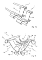
- FIG. 9 shows a further alternative embodiment of a coupling element 4d as a further development of the already in FIG. 4 shown coupling element 4c.
- the metal strips 13d present here are each fixed in the region of their folds 19a, 19b both on the upper flange 6 and on the lower chords 5a, 5b. In these areas, the metal strip 13d are joined in a manner not shown both with the upper flange 6 and with the lower chords 5a, 5b.
- FIG. 10 shows that already in FIG. 9 illustrated coupling element 4d to illustrate two schematically illustrated and stacked lattice girders. 1
- FIG. 11 shows a further embodiment of a coupling element 4e at one end 2, 3 of a lattice girder 1.
- the coupling element 4d FIG. 9 and 10 has the coupling element 4e here present in the region of its metal strip 13e another fold 20, which is located between the end loops 14e. These bends 20 are directed towards the outside 17 of the metal strip 13e out, resulting in an enlarged opening way of the lattice girder 1 between its upper flange 6 and its two lower chords 5a, 5b.
- the transverse web 12a shown here has a curved course.
- the opening width between the upper flange 6 and the two lower chords 5a, 5b of the lattice girder 1 is additionally increased, wherein the transverse bar 12a opens to the lower chords 5a, 5b.
- a transverse web 12 With respect to the straight embodiment of a transverse web 12, it is preferably spaced from the ground plane B such that a distance between the struts 8a-8d below the transverse web 12 to the ground plane A is at most an outer width between two loops 14, 14a-14e in FIG Area of upper girth 6 corresponds.
Landscapes
- Engineering & Computer Science (AREA)
- Architecture (AREA)
- Structural Engineering (AREA)
- Civil Engineering (AREA)
- Mining & Mineral Resources (AREA)
- Life Sciences & Earth Sciences (AREA)
- General Life Sciences & Earth Sciences (AREA)
- Geochemistry & Mineralogy (AREA)
- Geology (AREA)
- Bridges Or Land Bridges (AREA)
- Lining And Supports For Tunnels (AREA)
Applications Claiming Priority (1)
| Application Number | Priority Date | Filing Date | Title |
|---|---|---|---|
| DE102012108471A DE102012108471B3 (de) | 2012-09-11 | 2012-09-11 | Gitterträger |
Publications (2)
| Publication Number | Publication Date |
|---|---|
| EP2706193A2 true EP2706193A2 (fr) | 2014-03-12 |
| EP2706193A3 EP2706193A3 (fr) | 2015-07-29 |
Family
ID=49003688
Family Applications (1)
| Application Number | Title | Priority Date | Filing Date |
|---|---|---|---|
| EP13181143.2A Withdrawn EP2706193A3 (fr) | 2012-09-11 | 2013-08-21 | Support de grille |
Country Status (3)
| Country | Link |
|---|---|
| US (1) | US9010061B2 (fr) |
| EP (1) | EP2706193A3 (fr) |
| DE (1) | DE102012108471B3 (fr) |
Families Citing this family (7)
| Publication number | Priority date | Publication date | Assignee | Title |
|---|---|---|---|---|
| US9611652B2 (en) * | 2011-02-25 | 2017-04-04 | Dustin M. M. Haddock | Mounting device for building surfaces having elongated mounting slot |
| US10557266B2 (en) | 2017-06-02 | 2020-02-11 | Austin Building And Design Inc. | Girders, joists and roof system |
| US11286667B2 (en) * | 2017-12-01 | 2022-03-29 | Armatron Systems, LLC | Seismic foundation framer and method of forming a foundation using same |
| CL2019000711A1 (es) * | 2019-02-20 | 2019-08-16 | Dsi Tunneling Llc | Sistema y procedimiento para soporte de tunel. |
| CN110230502B (zh) * | 2019-06-20 | 2024-08-16 | 中铁第四勘察设计院集团有限公司 | 一种简支式盾构隧道中隔墙安装结构及方法 |
| USD942700S1 (en) | 2019-08-14 | 2022-02-01 | Cleophus Maxwell McIntosh | Impact absorbing lattice |
| US11242750B2 (en) | 2019-11-25 | 2022-02-08 | Fci Holdings Delaware, Inc. | Adjustable lattice girder |
Citations (2)
| Publication number | Priority date | Publication date | Assignee | Title |
|---|---|---|---|---|
| DE8125375U1 (de) | 1981-09-01 | 1982-01-21 | Pantex-Stahl AG, 6233 Büron | Gittertraeger fuer den untertag-strecken- und schachtausbau |
| DE202010004389U1 (de) | 2010-03-31 | 2010-07-01 | Bochumer Eisenhütte Heintzmann GmbH & Co. KG | Gitterträger |
Family Cites Families (21)
| Publication number | Priority date | Publication date | Assignee | Title |
|---|---|---|---|---|
| US1181013A (en) * | 1915-10-09 | 1916-04-25 | Charles Edward Inglis | Military bridge and the like. |
| US1472654A (en) * | 1919-09-12 | 1923-10-30 | Jackson George | Building construction |
| US1545129A (en) * | 1923-09-27 | 1925-07-07 | Jr John F Cook | Aircraft structure |
| US1629367A (en) * | 1926-02-19 | 1927-05-17 | Robert E Cowden | Partition unit and construction |
| US2241617A (en) * | 1940-07-27 | 1941-05-13 | Allen I Rubin | Triangular joist |
| DK134190B (da) * | 1973-02-02 | 1976-09-27 | Villadsens Fab As Jens | Halkonstruktion med 3-charnier gitterbuer. |
| US3974777A (en) * | 1974-10-29 | 1976-08-17 | Maxime Monne | Rolling element for a handling equipment and equipments comprising such elements |
| AT345331B (de) * | 1976-05-07 | 1978-09-11 | Gd Anker Gmbh & Co Kg | Tunnelverzugselement |
| DE8206277U1 (de) * | 1982-03-06 | 1982-06-24 | Bochumer Eisenhütte Heintzmann GmbH & Co KG, 4630 Bochum | Gitterartiger ausbaurahmen |
| US4543761A (en) * | 1982-06-16 | 1985-10-01 | Grumman Aerospace Corporation | Joining techniques for large structures |
| DE8431104U1 (de) * | 1984-10-23 | 1985-05-15 | Tunnel Ausbau Technik GmbH, 8036 Herrsching | Ausbaurahmen zur Gebirgssicherung bei voreilenden Kalottenvortrieb im Tunnel-Teilausbruchverfahren |
| JP2843494B2 (ja) * | 1994-03-18 | 1999-01-06 | ワイケイケイアーキテクチュラルプロダクツ株式会社 | 構造部材 |
| DE19711627C2 (de) * | 1996-12-02 | 1997-12-11 | Seiz Rudolf | Gitterträgerausbaurahmen und Aussteifungselemente für einen Gitterträgerausbaurahmen |
| US6079178A (en) * | 1998-10-09 | 2000-06-27 | Tomcat Global Corporation | U-shaped stackable truss |
| US7347030B2 (en) * | 2003-01-21 | 2008-03-25 | Steve Lewison | Modular truss system with a nesting storage configuration |
| US6745539B1 (en) * | 2003-03-14 | 2004-06-08 | Fred F. Heim | Lattice tower |
| DE10336154B4 (de) * | 2003-08-07 | 2006-09-21 | Bochumer Eisenhütte Heintzmann GmbH & Co. KG | Parallelgurtträger, insbesondere für den Streckenausbau und Tunnelausbau |
| US8307609B2 (en) * | 2010-04-01 | 2012-11-13 | Korea Electric Power Corporation | Reinforcement device for lateral buckling stress and method of engaging reinforcement device |
| JP2011219968A (ja) * | 2010-04-08 | 2011-11-04 | Matsui Kanaami Kogyo Kk | アーチ型トラス |
| KR101028512B1 (ko) * | 2010-07-27 | 2011-04-11 | 그린컨기술주식회사 | 터널시공용 격자지보 및 그 제작방법 |
| CA2813238A1 (fr) * | 2010-10-08 | 2012-04-12 | Cablofil, Inc. | Structure de support et systemes la comportant |
-
2012
- 2012-09-11 DE DE102012108471A patent/DE102012108471B3/de not_active Expired - Fee Related
-
2013
- 2013-08-21 EP EP13181143.2A patent/EP2706193A3/fr not_active Withdrawn
- 2013-09-03 US US14/016,800 patent/US9010061B2/en not_active Expired - Fee Related
Patent Citations (2)
| Publication number | Priority date | Publication date | Assignee | Title |
|---|---|---|---|---|
| DE8125375U1 (de) | 1981-09-01 | 1982-01-21 | Pantex-Stahl AG, 6233 Büron | Gittertraeger fuer den untertag-strecken- und schachtausbau |
| DE202010004389U1 (de) | 2010-03-31 | 2010-07-01 | Bochumer Eisenhütte Heintzmann GmbH & Co. KG | Gitterträger |
Also Published As
| Publication number | Publication date |
|---|---|
| US9010061B2 (en) | 2015-04-21 |
| US20140069047A1 (en) | 2014-03-13 |
| DE102012108471B3 (de) | 2013-09-26 |
| EP2706193A3 (fr) | 2015-07-29 |
Similar Documents
| Publication | Publication Date | Title |
|---|---|---|
| DE102012108471B3 (de) | Gitterträger | |
| EP2372082B1 (fr) | Support de grille | |
| EP2108071B1 (fr) | Rail de grue soudé au laser pour chariot de pont roulant | |
| EP2873786B1 (fr) | Grand tube à double paroi, utilisation et procédé de fabrication d'un grand tube à double paroi | |
| DE102007047438A1 (de) | Schalungsanordnung für den Freivorbau von Brücken | |
| DD271307A5 (de) | Druckfester tank | |
| WO2016030342A1 (fr) | Mât articulé | |
| DE1559490B1 (de) | Bewehrungselement fuer Balken und Stuetzen aus Stahlbeton | |
| DE19711627C2 (de) | Gitterträgerausbaurahmen und Aussteifungselemente für einen Gitterträgerausbaurahmen | |
| DE102012108020A1 (de) | Doppel-U-Gerüstriegel | |
| EP0410335B1 (fr) | Elément de renforcement pour la formation de cadres de support dans la construction de tunnels | |
| DE202012103456U1 (de) | Gitterträger | |
| DE102010012381A1 (de) | Knotenverbindung für ebene und/oder räumliche Tragwerke als Stahl- oder Stahlverbundkonstruktion auf dem Gebiet des Brückenbaus sowie im Hoch- und Wasserbau | |
| DE202012103457U1 (de) | Gitterträger | |
| EP1921225B1 (fr) | Élément de coffrage avec raidissement | |
| DE2403717A1 (de) | Verbindungsanker fuer sandwich-bauweise | |
| AT257901B (de) | Tafelförmiges Bauelement | |
| EP2706194A2 (fr) | Support de grille | |
| DE2234941A1 (de) | Bewehrung fuer vorgefertigte stahlbetonwaende oder -platten | |
| DE60007824T2 (de) | Gitterträger | |
| DE2109375C3 (de) | Bewehrung für Betonbauteile | |
| EP0086993B1 (fr) | Poutre en treillis | |
| DE10214051A1 (de) | Faltbarer Hohlträger, insbesondere Längsträger für ein Fahrzeug | |
| DE3713152C1 (en) | Box-type telescoping crane jib | |
| AT404955B (de) | Formrohr |
Legal Events
| Date | Code | Title | Description |
|---|---|---|---|
| PUAI | Public reference made under article 153(3) epc to a published international application that has entered the european phase |
Free format text: ORIGINAL CODE: 0009012 |
|
| AK | Designated contracting states |
Kind code of ref document: A2 Designated state(s): AL AT BE BG CH CY CZ DE DK EE ES FI FR GB GR HR HU IE IS IT LI LT LU LV MC MK MT NL NO PL PT RO RS SE SI SK SM TR |
|
| AX | Request for extension of the european patent |
Extension state: BA ME |
|
| PUAL | Search report despatched |
Free format text: ORIGINAL CODE: 0009013 |
|
| AK | Designated contracting states |
Kind code of ref document: A3 Designated state(s): AL AT BE BG CH CY CZ DE DK EE ES FI FR GB GR HR HU IE IS IT LI LT LU LV MC MK MT NL NO PL PT RO RS SE SI SK SM TR |
|
| AX | Request for extension of the european patent |
Extension state: BA ME |
|
| RIC1 | Information provided on ipc code assigned before grant |
Ipc: E04C 5/16 20060101ALI20150622BHEP Ipc: E21D 11/10 20060101AFI20150622BHEP Ipc: E04C 3/08 20060101ALI20150622BHEP |
|
| STAA | Information on the status of an ep patent application or granted ep patent |
Free format text: STATUS: THE APPLICATION IS DEEMED TO BE WITHDRAWN |
|
| 18D | Application deemed to be withdrawn |
Effective date: 20160130 |