EP2706202A2 - Dispositif de commande de synchronisation d'ouverture/fermeture de soupape - Google Patents
Dispositif de commande de synchronisation d'ouverture/fermeture de soupape Download PDFInfo
- Publication number
- EP2706202A2 EP2706202A2 EP13164526.9A EP13164526A EP2706202A2 EP 2706202 A2 EP2706202 A2 EP 2706202A2 EP 13164526 A EP13164526 A EP 13164526A EP 2706202 A2 EP2706202 A2 EP 2706202A2
- Authority
- EP
- European Patent Office
- Prior art keywords
- phase
- retarded angle
- locking
- relative rotational
- rotating body
- Prior art date
- Legal status (The legal status is an assumption and is not a legal conclusion. Google has not performed a legal analysis and makes no representation as to the accuracy of the status listed.)
- Ceased
Links
Images




Classifications
-
- F—MECHANICAL ENGINEERING; LIGHTING; HEATING; WEAPONS; BLASTING
- F01—MACHINES OR ENGINES IN GENERAL; ENGINE PLANTS IN GENERAL; STEAM ENGINES
- F01L—CYCLICALLY OPERATING VALVES FOR MACHINES OR ENGINES
- F01L1/00—Valve-gear or valve arrangements, e.g. lift-valve gear
- F01L1/34—Valve-gear or valve arrangements, e.g. lift-valve gear characterised by the provision of means for changing the timing of the valves without changing the duration of opening and without affecting the magnitude of the valve lift
-
- F—MECHANICAL ENGINEERING; LIGHTING; HEATING; WEAPONS; BLASTING
- F01—MACHINES OR ENGINES IN GENERAL; ENGINE PLANTS IN GENERAL; STEAM ENGINES
- F01L—CYCLICALLY OPERATING VALVES FOR MACHINES OR ENGINES
- F01L1/00—Valve-gear or valve arrangements, e.g. lift-valve gear
- F01L1/34—Valve-gear or valve arrangements, e.g. lift-valve gear characterised by the provision of means for changing the timing of the valves without changing the duration of opening and without affecting the magnitude of the valve lift
- F01L1/344—Valve-gear or valve arrangements, e.g. lift-valve gear characterised by the provision of means for changing the timing of the valves without changing the duration of opening and without affecting the magnitude of the valve lift changing the angular relationship between crankshaft and camshaft, e.g. using helicoidal gear
- F01L1/3442—Valve-gear or valve arrangements, e.g. lift-valve gear characterised by the provision of means for changing the timing of the valves without changing the duration of opening and without affecting the magnitude of the valve lift changing the angular relationship between crankshaft and camshaft, e.g. using helicoidal gear using hydraulic chambers with variable volume to transmit the rotating force
-
- F—MECHANICAL ENGINEERING; LIGHTING; HEATING; WEAPONS; BLASTING
- F02—COMBUSTION ENGINES; HOT-GAS OR COMBUSTION-PRODUCT ENGINE PLANTS
- F02D—CONTROLLING COMBUSTION ENGINES
- F02D13/00—Controlling the engine output power by varying inlet or exhaust valve operating characteristics, e.g. timing
- F02D13/02—Controlling the engine output power by varying inlet or exhaust valve operating characteristics, e.g. timing during engine operation
- F02D13/0223—Variable control of the intake valves only
- F02D13/0234—Variable control of the intake valves only changing the valve timing only
- F02D13/0238—Variable control of the intake valves only changing the valve timing only by shifting the phase, i.e. the opening periods of the valves are constant
-
- F—MECHANICAL ENGINEERING; LIGHTING; HEATING; WEAPONS; BLASTING
- F02—COMBUSTION ENGINES; HOT-GAS OR COMBUSTION-PRODUCT ENGINE PLANTS
- F02D—CONTROLLING COMBUSTION ENGINES
- F02D41/00—Electrical control of supply of combustible mixture or its constituents
- F02D41/02—Circuit arrangements for generating control signals
- F02D41/021—Introducing corrections for particular conditions exterior to the engine
- F02D41/0215—Introducing corrections for particular conditions exterior to the engine in relation with elements of the transmission
- F02D41/0225—Introducing corrections for particular conditions exterior to the engine in relation with elements of the transmission in relation with the gear ratio or shift lever position
-
- F—MECHANICAL ENGINEERING; LIGHTING; HEATING; WEAPONS; BLASTING
- F02—COMBUSTION ENGINES; HOT-GAS OR COMBUSTION-PRODUCT ENGINE PLANTS
- F02D—CONTROLLING COMBUSTION ENGINES
- F02D41/00—Electrical control of supply of combustible mixture or its constituents
- F02D41/02—Circuit arrangements for generating control signals
- F02D41/04—Introducing corrections for particular operating conditions
- F02D41/042—Introducing corrections for particular operating conditions for stopping the engine
-
- F—MECHANICAL ENGINEERING; LIGHTING; HEATING; WEAPONS; BLASTING
- F01—MACHINES OR ENGINES IN GENERAL; ENGINE PLANTS IN GENERAL; STEAM ENGINES
- F01L—CYCLICALLY OPERATING VALVES FOR MACHINES OR ENGINES
- F01L1/00—Valve-gear or valve arrangements, e.g. lift-valve gear
- F01L1/34—Valve-gear or valve arrangements, e.g. lift-valve gear characterised by the provision of means for changing the timing of the valves without changing the duration of opening and without affecting the magnitude of the valve lift
- F01L1/344—Valve-gear or valve arrangements, e.g. lift-valve gear characterised by the provision of means for changing the timing of the valves without changing the duration of opening and without affecting the magnitude of the valve lift changing the angular relationship between crankshaft and camshaft, e.g. using helicoidal gear
- F01L1/3442—Valve-gear or valve arrangements, e.g. lift-valve gear characterised by the provision of means for changing the timing of the valves without changing the duration of opening and without affecting the magnitude of the valve lift changing the angular relationship between crankshaft and camshaft, e.g. using helicoidal gear using hydraulic chambers with variable volume to transmit the rotating force
- F01L2001/3445—Details relating to the hydraulic means for changing the angular relationship
- F01L2001/34453—Locking means between driving and driven members
- F01L2001/34459—Locking in multiple positions
-
- F—MECHANICAL ENGINEERING; LIGHTING; HEATING; WEAPONS; BLASTING
- F01—MACHINES OR ENGINES IN GENERAL; ENGINE PLANTS IN GENERAL; STEAM ENGINES
- F01L—CYCLICALLY OPERATING VALVES FOR MACHINES OR ENGINES
- F01L1/00—Valve-gear or valve arrangements, e.g. lift-valve gear
- F01L1/34—Valve-gear or valve arrangements, e.g. lift-valve gear characterised by the provision of means for changing the timing of the valves without changing the duration of opening and without affecting the magnitude of the valve lift
- F01L1/344—Valve-gear or valve arrangements, e.g. lift-valve gear characterised by the provision of means for changing the timing of the valves without changing the duration of opening and without affecting the magnitude of the valve lift changing the angular relationship between crankshaft and camshaft, e.g. using helicoidal gear
- F01L1/3442—Valve-gear or valve arrangements, e.g. lift-valve gear characterised by the provision of means for changing the timing of the valves without changing the duration of opening and without affecting the magnitude of the valve lift changing the angular relationship between crankshaft and camshaft, e.g. using helicoidal gear using hydraulic chambers with variable volume to transmit the rotating force
- F01L2001/3445—Details relating to the hydraulic means for changing the angular relationship
- F01L2001/34453—Locking means between driving and driven members
- F01L2001/34463—Locking position intermediate between most retarded and most advanced positions
-
- F—MECHANICAL ENGINEERING; LIGHTING; HEATING; WEAPONS; BLASTING
- F01—MACHINES OR ENGINES IN GENERAL; ENGINE PLANTS IN GENERAL; STEAM ENGINES
- F01L—CYCLICALLY OPERATING VALVES FOR MACHINES OR ENGINES
- F01L1/00—Valve-gear or valve arrangements, e.g. lift-valve gear
- F01L1/34—Valve-gear or valve arrangements, e.g. lift-valve gear characterised by the provision of means for changing the timing of the valves without changing the duration of opening and without affecting the magnitude of the valve lift
- F01L1/344—Valve-gear or valve arrangements, e.g. lift-valve gear characterised by the provision of means for changing the timing of the valves without changing the duration of opening and without affecting the magnitude of the valve lift changing the angular relationship between crankshaft and camshaft, e.g. using helicoidal gear
- F01L1/3442—Valve-gear or valve arrangements, e.g. lift-valve gear characterised by the provision of means for changing the timing of the valves without changing the duration of opening and without affecting the magnitude of the valve lift changing the angular relationship between crankshaft and camshaft, e.g. using helicoidal gear using hydraulic chambers with variable volume to transmit the rotating force
- F01L2001/3445—Details relating to the hydraulic means for changing the angular relationship
- F01L2001/34453—Locking means between driving and driven members
- F01L2001/34466—Locking means between driving and driven members with multiple locking devices
-
- F—MECHANICAL ENGINEERING; LIGHTING; HEATING; WEAPONS; BLASTING
- F02—COMBUSTION ENGINES; HOT-GAS OR COMBUSTION-PRODUCT ENGINE PLANTS
- F02D—CONTROLLING COMBUSTION ENGINES
- F02D41/00—Electrical control of supply of combustible mixture or its constituents
- F02D41/0002—Controlling intake air
- F02D2041/001—Controlling intake air for engines with variable valve actuation
-
- F—MECHANICAL ENGINEERING; LIGHTING; HEATING; WEAPONS; BLASTING
- F02—COMBUSTION ENGINES; HOT-GAS OR COMBUSTION-PRODUCT ENGINE PLANTS
- F02D—CONTROLLING COMBUSTION ENGINES
- F02D2200/00—Input parameters for engine control
- F02D2200/02—Input parameters for engine control the parameters being related to the engine
- F02D2200/021—Engine temperature
-
- F—MECHANICAL ENGINEERING; LIGHTING; HEATING; WEAPONS; BLASTING
- F02—COMBUSTION ENGINES; HOT-GAS OR COMBUSTION-PRODUCT ENGINE PLANTS
- F02D—CONTROLLING COMBUSTION ENGINES
- F02D2400/00—Control systems adapted for specific engine types; Special features of engine control systems not otherwise provided for; Power supply, connectors or cabling for engine control systems
- F02D2400/12—Engine control specially adapted for a transmission comprising a torque converter or for continuously variable transmissions
-
- F—MECHANICAL ENGINEERING; LIGHTING; HEATING; WEAPONS; BLASTING
- F02—COMBUSTION ENGINES; HOT-GAS OR COMBUSTION-PRODUCT ENGINE PLANTS
- F02D—CONTROLLING COMBUSTION ENGINES
- F02D41/00—Electrical control of supply of combustible mixture or its constituents
- F02D41/02—Circuit arrangements for generating control signals
- F02D41/04—Introducing corrections for particular operating conditions
- F02D41/06—Introducing corrections for particular operating conditions for engine starting or warming up
- F02D41/062—Introducing corrections for particular operating conditions for engine starting or warming up for starting
- F02D41/065—Introducing corrections for particular operating conditions for engine starting or warming up for starting at hot start or restart
-
- F—MECHANICAL ENGINEERING; LIGHTING; HEATING; WEAPONS; BLASTING
- F02—COMBUSTION ENGINES; HOT-GAS OR COMBUSTION-PRODUCT ENGINE PLANTS
- F02N—STARTING OF COMBUSTION ENGINES; STARTING AIDS FOR SUCH ENGINES, NOT OTHERWISE PROVIDED FOR
- F02N11/00—Starting of engines by means of electric motors
- F02N11/08—Circuits specially adapted for starting of engines
- F02N11/0814—Circuits specially adapted for starting of engines comprising means for controlling automatic idle-start-stop
-
- F—MECHANICAL ENGINEERING; LIGHTING; HEATING; WEAPONS; BLASTING
- F02—COMBUSTION ENGINES; HOT-GAS OR COMBUSTION-PRODUCT ENGINE PLANTS
- F02N—STARTING OF COMBUSTION ENGINES; STARTING AIDS FOR SUCH ENGINES, NOT OTHERWISE PROVIDED FOR
- F02N19/00—Starting aids for combustion engines, not otherwise provided for
- F02N19/004—Aiding engine start by using decompression means or variable valve actuation
-
- F—MECHANICAL ENGINEERING; LIGHTING; HEATING; WEAPONS; BLASTING
- F02—COMBUSTION ENGINES; HOT-GAS OR COMBUSTION-PRODUCT ENGINE PLANTS
- F02N—STARTING OF COMBUSTION ENGINES; STARTING AIDS FOR SUCH ENGINES, NOT OTHERWISE PROVIDED FOR
- F02N2200/00—Parameters used for control of starting apparatus
- F02N2200/08—Parameters used for control of starting apparatus said parameters being related to the vehicle or its components
- F02N2200/0802—Transmission state, e.g. gear ratio or neutral state
-
- Y—GENERAL TAGGING OF NEW TECHNOLOGICAL DEVELOPMENTS; GENERAL TAGGING OF CROSS-SECTIONAL TECHNOLOGIES SPANNING OVER SEVERAL SECTIONS OF THE IPC; TECHNICAL SUBJECTS COVERED BY FORMER USPC CROSS-REFERENCE ART COLLECTIONS [XRACs] AND DIGESTS
- Y02—TECHNOLOGIES OR APPLICATIONS FOR MITIGATION OR ADAPTATION AGAINST CLIMATE CHANGE
- Y02T—CLIMATE CHANGE MITIGATION TECHNOLOGIES RELATED TO TRANSPORTATION
- Y02T10/00—Road transport of goods or passengers
- Y02T10/10—Internal combustion engine [ICE] based vehicles
- Y02T10/12—Improving ICE efficiencies
Definitions
- This disclosure relates to a valve open/close timing control device for controlling open/close timing of an intake valve and an exhaust valve of an internal combustion engine used in an automobile.
- JP 2011-1888 A discloses a valve open/close timing control device which includes: a drive-side rotating body ("outer rotor” in Reference 1); a driven-side rotating body ("inner rotor” in Reference 1); a fluid pressure chamber which is partitioned into retarded angle chambers and advanced angle chambers by partition portions ("vanes" in Reference 1) which are formed by the drive-side rotating body and the driven-side rotating body, and are mounted on the driven-side rotating body; and a fluid control mechanism (“control valve” in Reference 1) which controls the supply of working fluid from a working fluid pump (“oil pump” or the like in Reference 1) which supplies working fluid to a fluid pressure chamber and the discharge of the working fluid from the fluid pressure chamber.
- the valve open/close timing control device described in Reference 1 includes an intermediate phase fixing means which can fix a relative rotational phase of the driven-side rotating body with respect to the drive-side rotating body at a predetermined intermediate phase between a most retarded angle phase and a most advanced angle phase.
- the intermediate phase fixing means includes a locking key which is mounted on a drive-side rotating body side and a locking releasing hydraulic chamber formed in the driven-side rotating body, and the relative rotational phase is fixed at a predetermined intermediate phase due to the engagement of the locking key with the locking releasing hydraulic chamber.
- valve open/close timing control device includes a stop-time phase change means which changes the relative rotational phase to the predetermined intermediate phase when a stop signal for stopping an internal combustion engine is detected. Accordingly, when the ignition is turned off, it is possible to stop the internal combustion engine after the relative rotational phase is fixed at the intermediate phase where the valve open/close timing is suitable for starting the internal combustion engine.
- the engine can be restarted in a state where the relative rotational phase is surely restrained to the predetermined phase. Accordingly, by setting the predetermined phase to a desired phase, the relationship between intake timing and ignition timing can be optimized so that startability of the engine can be enhanced. For example, it is possible to acquire a low-emission-type engine which emits a small amount of harmful combustion waste such as hydrogen carbide (HC).
- HC hydrogen carbide
- the occurrence of the pre-ignition can be suppressed by lowering an actual compression ratio by changing closing timing to a retarded angle side using a variable valve timing mechanism. Accordingly, at the time of warm-starting the high compression engine, it is suitable to use a locking phase close to a most retarded angle side as the relative rotational phase of the valve open/close timing control device.
- the engine is usually started using a starter (cell motor) in cold start, and a rotational speed of cranking in cold start is lower than a rotational speed of cranking in warm start and hence, in-cylinder pressure is hardly elevated. Accordingly, in cold start, an intermediate locking phase where the in-cylinder pressure is easily elevated is suitable as a relative rotational phase.
- the engine acquires an output by compressing air and fuel in the form of an air-fuel mixture and by igniting the air-fuel mixture.
- an engine which repeatedly performs start and stop of the engine such as a hybrid engine or an engine which has an idling stop function
- the vibrations of the engine in start can be suppressed by suppressing the compression of air. Accordingly, in restart of a hybrid engine in a warm state or in restart of the engine after an idling stop, a locking phase near a most retarded angle is suitable as a relative rotational phase.
- the number of phases suitable for starting an internal combustion engine is not limited to one phase.
- a valve open/close timing control device includes:
- the relative rotational phase can be restrained to the different valve timing phases such as the first predetermined phase and the second predetermined phase by the first locking mechanism and the second locking mechanism. Accordingly, the engine can be started at an optimum predetermined phase corresponding to a state of the internal combustion engine thus enhancing comfortability of driving.
- the valve open/close timing control device is configured such that the operation of changing the relative rotational phase to the first predetermined phase is started at the time of changing the shift lever position to the parking range before the turn-off operation of the ignition key. Accordingly, a delay control is started at an early stage before the turn-off operation of the ignition key so that undesired fuel consumption can be suppressed. As a result, the fuel economy can be enhanced. Further, since the delay control is completed before the turn-off operation of the ignition key so that the internal combustion engine is readily stopped when the ignition key is turned off. Accordingly, a driver feels no discomfort in an operation of stopping the internal combustion engine after turning off the ignition key.
- the first locking mechanism is constituted of a ratchet mechanism which includes a locking groove which is deepened in a stepwise manner and a locking member which is engageable with the locking groove, and the internal combustion engine is stopped in response to the detection of the engagement of at least a portion of the locking member with the locking groove due to the operation of changing the shift lever position to the parking range.
- a locking state where the relative rotational phase becomes the first predetermined phase is established after the ignition key is turned off and, thereafter, the internal combustion engine is stopped.
- the internal combustion engine is stopped in response to the detection of the engagement of at least a portion of the locking member with the locking groove in the first locking mechanism due to the operation of changing the shift lever position to the parking range. Accordingly, the internal combustion engine can be stopped at an early stage of the engagement of the locking member with the locking groove so that timing that the internal combustion engine is stopped can be advanced. As a result, the further enhancement of fuel economy can be realized.
- the ratchet mechanism functions so that the locking member is surely engaged with the locking groove. Accordingly, the relative rotational phase is held at the first predetermined phase at the time of starting the internal combustion engine and hence, the internal combustion engine can be started in a state where the relative rotational phase is in a first predetermined phase.
- An embodiment disclosed here will be a valve open/close timing control device on an intake valve side of an engine for an automobile and will is explained with reference to the attached Fig. 1 to Fig. 7 . That is, the engine for an automobile corresponds to "internal combustion engine" according to this disclosure.
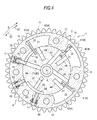
- the valve open/close timing control device includes, as shown in Fig. 1 , a housing 1 which constitutes a "drive-side rotating body” and is rotated synchronously with a crankshaft C of an engine 100, and an inner rotor 2 which constitutes a "driven-side rotating body” and is arranged coaxially with the housing 1 and in a rotatable manner relative to the housing 1 and is rotatable simultaneously with a camshaft 101.
- the camshaft 101 is a rotary shaft of a cam not shown in the drawing used for controlling opening/closing of an intake valve of the engine 100.
- the camshaft 101 is rotatably assembled to a cylinder head of the engine 100.
- the valve open/close timing control device includes an intermediate locking mechanism 6 which constitutes a "first locking mechanism” capable of restraining a relative rotational phase of the inner rotor 2 relative to the housing 1 to a first predetermined phase between a most retarded angle phase and a most advanced angle phase by restraining the relative rotational movement of the inner rotor 2 relative to the housing 1.
- the valve open/close timing control device also includes a most retarded angle locking mechanism 7 which constitutes a "second locking mechanism” capable of restraining the relative rotational phase to a second predetermined phase which is on a more retarded angle side than the first predetermined phase.
- the inner rotor 2 is, as shown in Fig. 1 , integrally assembled to a distal end portion of the camshaft 101.
- the inner rotor 2 is fastened and fixed to the distal end portion of the camshaft 101 by a bolt.
- the housing 1 includes a front plate 11 which is arranged on a side opposite to a side where the camshaft 101 is connected, an outer rotor 12 on which a timing sprocket 15 is integrally formed, and a rear plate 13 which is arranged on a side where the camshaft 101 is connected.
- the outer rotor 12 is exteriorly mounted on the inner rotor 2, the outer rotor 12 is sandwiched between the front plate 11 and the rear plate 13, and the front plate 11, the outer rotor 12 and the rear plate 13 are fastened together by bolts.
- the rotational driving of the crankshaft C is transmitted to the timing sprocket 15 by way of a power transmission member 102 so that the housing 1 is rotatably driven in the rotational direction S shown in Fig. 2 .
- the inner rotor 2 is rotated in the rotational direction S so that the camshaft 101 is rotated.
- a cam mounted on the camshaft 101 pushes down an intake valve of the engine 100 so as to open the intake valve.
- a plurality of projecting portions 14 which project in the radially inward direction are formed on the outer rotor 12 in a spaced-apart manner from each other along the rotational direction S, and a fluid pressure chamber 4 is formed between the outer rotor 12 and the inner rotor 2.
- the projecting portions 14 function as shoes with respect to an outer peripheral surface 2a of the inner rotor 2.
- the fluid pressure chamber 4 is formed at three places.
- the fluid pressure chamber 4 is not limited to such a constitution.
- a vane groove 21 is formed on a portion of the outer peripheral surface 2a which faces the fluid pressure chamber 4.
- a vane 22 which constitutes a "partitioning portion” is arranged in the inside of the vane groove 21 in a radially outwardly extending manner.
- the fluid pressure chamber 4 is partitioned into an advanced angle chamber 41 and a retarded angle chamber 42 along the rotational direction S by the vane 22.
- advanced angle passages 43 are formed in the inner rotor 2 and the camshaft 101 in such a manner that the advanced angle passage 43 is communicated with each advanced angle chamber 41.
- retarded angle passages 44 are formed in the inner rotor 2 and the camshaft 101 in such a manner that the retarded angle passage 44 is communicated with each retarded angle chamber 42.
- the advanced angle passages 43 and the retarded angle passages 44 are connected to a predetermined port (not shown in the drawing) of an OCV 9 which constitutes a fluid control mechanism described later.
- Working fluid is supplied to or discharged from the advanced angle chambers 41 and the retarded angle chambers 42 or a supply/discharge amount of working fluid is held by controlling the OCV 9 thus applying a fluid pressure of the working fluid to the vanes 22.
- a relative rotational phase is displaced in the advanced angle direction or in the retarded angle direction or is held at an arbitrary phase.
- the advanced angle direction is the direction that the vane 22 rotatably moves relative to the housing 1 so that a volume of the advanced angle chamber 41 is increased, and is indicated by an arrow S1 in Fig. 2 .
- the retarded angle direction is the direction that a volume of the retarded angle chamber 42 is increased, and is indicated by an arrow S2 in Fig. 2 .
- the inner rotor 2 is smoothly rotatably movable relative to the housing 1 within a fixed range about a rotary axis X.
- the fixed range in which the housing 1 and the inner rotor 2 are rotatably movable relative to each other, that is, the phase difference between the most advanced angle phase and the most retarded angle phase corresponds to a range where the vane 22 is displaceable in the inside of the fluid pressure chamber 4.
- the most retarded angle phase is a phase at which the volume of the retarded angle chamber 42 becomes the largest
- the most advanced angle phase is the phase at which the volume of the advanced angle chamber 41 becomes the largest.
- the intermediate locking mechanism 6 is provided for restraining the relative rotational phase to the intermediate locking phase which is the "first predetermined phase" between the most retarded angle phase and the most advanced angle phase by holding the housing 1 and the inner rotor 2 at predetermined relative positions in a state where a fluid pressure of working fluid is not stable immediately after starting the engine 100 or at the time of stopping the engine 100. Due to the provision of the intermediate locking mechanism 6, the rotational phase of the camshaft 101 relative to the rotational phase of the crankshaft can be properly maintained thus realizing the stable rotation of the engine 100.
- the intermediate locking phase is set at the phase where valve opening timings of an intake valve and an exhaust valve (not shown in the drawing) partially overlap with each other. As a result, hydrogen carbide (HC) produced at the time of starting the engine 100 can be reduced thus providing the low-emission engine.
- HC hydrogen carbide
- the intermediate locking mechanism 6 includes, as shown in Fig. 1 and Fig. 2 , an intermediate lock passage 61, an intermediate locking groove 62, accommodating portions 63, plate-shaped intermediate locking members 64 and springs 65.
- the intermediate lock passage 61 is formed in the inner rotor 2 and the camshaft 101, and connects the intermediate locking groove 62 and an OSV 10 which is a "fluid switching mechanism" described later to each other.
- OSV 10 which is a "fluid switching mechanism" described later to each other.
- the intermediate locking groove 62 is formed on the outer peripheral surface 2a of the inner rotor 2, and has a fixed width in the relative rotational direction.
- the accommodating portion 63 is formed in the outer rotor 12 at two places. Two intermediate locking members 64 are arranged in the respective accommodating portions 63 respectively, and are extendable from or retractable into the accommodating portions 63 in the radial direction.
- the spring 65 is arranged in the accommodating portion 63, and biases each intermediate locking member 64 radially inwardly, that is, toward the intermediate locking groove 62 side.
- each intermediate locking member 64 projects into the intermediate locking groove 62.
- the respective intermediate locking members 64 are respectively simultaneously engaged with both ends of the intermediate locking groove 62 in the circumferential direction.
- the relative rotational movement of the inner rotor 2 with respect to the housing 1 is restrained so that the relative rotational phase is restrained to the intermediate locking phase.
- both intermediate locking members 64 are retracted into the accommodating portions 63 from the intermediate locking groove 62 so that the restraint of the relative rotational phase is released whereby the inner rotor 2 becomes rotatably movable relative to the housing 1.
- the state where the intermediate locking mechanism 6 restrains the relative rotational phase to the intermediate locking phase is referred to as the "intermediate locking state”.
- the state where the intermediate locking state is released is referred to as the "intermediate locking released state”.
- a pin shape or the like is suitably adopted besides a plate shape described in this embodiment.
- the most retarded angle locking mechanism 7 is provided for restraining the relative rotational phase to the most retarded angle phase which is the "second predetermined phase" by holding the housing 1 and the inner rotor 2 at predetermined relative positions at the time of low speed rotation such as at the time of idling operation, at the time of idling stop, at the time of restarting idling or the like. That is, irrelevant to a displacement force in the retarded angle direction or the advanced angle direction based on a change in torque of the camshaft, the relative rotational movement of the inner rotor 2 is prevented and hence, a stable idling operation state can be realized.
- the most retarded angle phase is the phase where valve closing timing of the exhaust valve and valve opening timing of the intake valve become substantially equal, and is the phase where an idling operation state becomes stable.
- the engine 100 can be started even when the relative rotational phase is at the most retarded angle phase.
- the most retarded angle locking mechanism 7 includes, as shown in Fig. 1 , Fig. 2 and Fig. 6 , a most retarded angle lock passage 71, a most retarded angle locking groove 72, an accommodating portion 73, a plate-shaped most retarded angle locking member 74 and a spring 75.
- the most retarded angle lock passage 71 also functions as one of the above-mentioned advanced angle passages 43, and connects the most retarded angle locking groove 72 and the OCV 9 to each other. Further, on the outer peripheral surface 2a of the inner rotor 2, an advanced angle chamber communication passage 76 which is a groove extending between the most retarded angle locking groove 72 and one of the vane grooves 21 in the circumferential direction is formed. When working fluid is supplied to or discharged from the advanced angle chamber 41 by the OSV 10, the working fluid is also supplied to or discharged from the most retarded angle locking groove 72.
- the accommodating portion 73 is formed in the outer rotor 12.
- the most retarded angle locking member 74 is arranged in the accommodating portion 73, and is extendable from or retractable into the accommodating portion 73 in the radial direction.
- the spring 75 is arranged in the accommodating portion 73, and biases the most retarded angle locking member 74 radially inwardly, that is, toward a most retarded angle locking groove 72 side.
- the most retarded angle locking member 74 projects into the most retarded angle locking groove 72.
- the most retarded angle locking member 74 is engaged with the most retarded angle locking groove 72 so that the relative rotational movement of the inner rotor 2 with respect to the housing 1 is restrained whereby the relative rotational phase is restrained to the most retarded angle phase.
- the working fluid is supplied to the most retarded angle locking groove 72 and hence, the most retarded angle locking member 74 is retracted into the accommodating portion 73 from the most retarded angle locking groove 72. That is, the restraint of the relative rotational phase is released.
- the state where the most retarded angle locking mechanism 7 restrains the relative rotational phase to the most retarded angle phase is referred to as the "most retarded angle locking state”.
- the state where the most retarded angle locking state is released is referred to as the "most retarded angle locking released state”.
- the most retarded angle locking member 74 When the relative rotational phase is at the phase other than the most retarded angle phase, the most retarded angle locking member 74 is positionally displaced from the most retarded angle locking groove 72 and hence, the most retarded angle locking member 74 is merely brought into slide contact with the outer peripheral surface 2a of the inner rotor 2.
- the relative rotational phase is at these phases, that is, when the most retarded angle locking member 74 is retracted from the most retarded angle locking groove 72, the most retarded angle lock passage 71 and the advanced angle chamber 41 are always communicated with each other through the advanced angle chamber communication passage 76.
- the advanced angle chamber communication passage 76 may not be formed into a groove shape, and may be formed into a shape where an outer peripheral corner portion of the inner rotor 2 is chamfered although not shown in the drawing.
- An oil pump 5 serving as the "working fluid pump” is driven by the engine 100 and supplies working oil which is one example of "working fluid".
- the oil pump 5 is a mechanical hydraulic pump which is driven with the transmission of a rotational drive force of the crankshaft.
- the oil pump 5, as shown in Fig. 1 sucks working oil in an oil pan 5a, and discharges the working oil toward a downstream side.
- the discharged working oil is supplied to the fluid pressure chamber 4 by way of a fluid control mechanism and a fluid switching mechanism described later. Further, the working oil discharged from the fluid pressure chamber 4 is returned to the oil pan 5a by way of the fluid control mechanism and the fluid switching mechanism.
- Working fluid leaked from the valve open/close timing control device is also recovered to the oil pan 5a.
- the valve open/close timing control device includes the electromagnetic control type OCV (oil control valve) 9 which is the "fluid control mechanism” and the electromagnetic control type OSV (oil switching valve) 10 which is the "fluid switching mechanism”.
- OCV 9 and the OSV 10 are connected to the oil pump 5 respectively.
- the supply and the discharge of working oil to and from the advanced angle passages 43, the most retarded angle lock passage 71 and the retarded angle passages 44, and the holding of a supply amount can be controlled.
- the supply and the discharge of working oil to and from the intermediate lock passage 61 can be switched.
- the OCV 9 has the spool type constitution, and is operated based on a control of an electricity supply amount performed by an ECU 8 (engine control unit).
- an ECU 8 engine control unit
- the supply of working oil to the advanced angle chamber 41, the discharge of working oil from the retarded angle chamber 42, the discharge of working oil from the advanced angle chamber 41, the supply of working oil to the retarded angle chamber 42, the interruption of the supply and the discharge of working oil to and from the advanced angle chamber 41 and the retarded angle chamber 42 can be controlled.
- the control which is performed for supplying working oil to the advanced angle chamber 41 and the control for discharging working oil from the retarded angle chamber 42 constitute the "advanced angle control".
- the vanes 22 When the advanced angle control is performed, the vanes 22 are rotatably moved in the advanced angle direction S1 relative to the outer rotor 12 and hence, the relative rotational phase is displaced toward the advanced angle side.
- the control which is performed for discharging working oil from the advanced angle chamber 41 and the control for supplying working oil to the retarded angle chamber 42 constitute the "retarded angle control".
- the retarded angle control When the retarded angle control is performed, the vanes 22 are rotatably moved in the retarded angle direction S2 relative to the outer rotor 12 and hence, the relative rotational phase is displaced toward the retarded angle side.
- the control When the control is performed for interrupting the supply and the discharge of working oil to and from the advanced angle chamber 41 and the retarded angle chamber 42, the relative rotational movement of the vanes 22 is prevented and hence, the relative rotational phase can be held at an arbitrary phase.
- the control of the valve open/close timing control device is set such that the retarded angle control enabling state is established when electricity is supplied to the OCV 9 (turning on the OCV 9), and the advanced angle control enabling state is established when the supply of the electricity to the OCV 9 is stopped (turning off the OCV 9).
- opening of the OCV 9 is set by adjusting a duty ratio of electricity supplied to an electromagnetic solenoid. Accordingly, a supply amount/discharge amount of working oil can be finely adjusted.
- the OSV 10 has a spool type constitution, and is operated based on switching between the supply of electricity to the ECU 8 and the stopping of the supply of electricity to the ECU 8. With the use of the OSV 10, the supply of working oil to the intermediate locking groove 62 and the discharge of the working oil from the intermediate locking groove 62 can be switched. In this embodiment, the OSV 10 is brought into a state where working oil can be discharged from the intermediate locking groove 62 when electricity is supplied to the OSV 10 (turning on the OSV 10), and the OSV 10 is brought into a state where working oil can be supplied to the intermediate locking groove 62 when the supply of electricity is stopped (turning off the OSV 10).
- a crank angle sensor which detects a rotational angle of the crankshaft C of the engine 100, and a camshaft angle sensor which detects a rotational angle of the camshaft 101 are provided to the valve open/close timing control device.
- the ECU 8 detects the relative rotational phase based on detection results from the crank angle sensor and the camshaft angle sensor, and determines the phase which the relative rotational phase assumes. Further, in the ECU 8, a signal system for acquiring ON/OFF information on the ignition key, information from an oil temperature sensor which detects an oil temperature of working oil and the like is formed. In a memory of the ECU 8, control information on an optimum relative rotational phase corresponding to the operation state of the engine 100 is stored. The ECU 8 controls the relative rotational phase based on information on an operation state (engine rotational speed, cooling water temperature or the like) and the above-mentioned control information.
- a torsion spring 3 is provided in an extending manner between the inner rotor 2 and the front plate 11.
- the torsion spring 3 biases the inner rotor 2 toward an advanced angle side such that the torsion spring 3 resists an average displacement force of the camshaft in the retarded angle direction based on a change in torque. Accordingly, the relative rotational phase can be smoothly and readily displaced in the advanced angle direction.
- valve open/close timing control device The manner of operation of the valve open/close timing control device is explained in conjunction with Fig. 2 to Fig. 5 .
- the timing chart of the displacement of the relative rotational phase, the state of the intermediate locking mechanism 6, the state of the most retarded angle locking mechanism 7, the control of the OCV 9 and the control of the OSV 10 from the start to the stop of the engine 100 is shown in Fig. 7 .
- the relative rotational phase Before the start of the engine 100, the relative rotational phase is in the intermediate locking state by the intermediate locking mechanism 6.
- the engine 100 is started in the state where the relative rotational phase is restrained to the intermediate locking phase (intermediate locking state) as shown in Fig. 2 , and the idling operation (before catalyst warming-up) is started. Electricity is supplied to the OSV 10 simultaneously with the turning on of the ignition key and hence, the intermediate locking state is maintained.
- the retarded angle control is performed by supplying electricity to the OCV 9, and working oil is supplied to the intermediate locking groove 62 by stopping the supply of electricity to the OSV 10. Accordingly, as shown in Fig. 3 , the intermediate locking members 64 are retracted from the intermediate locking groove 62 so that the intermediate locking released state is established. Due to such a retarded angle control, working oil in the most retarded angle locking groove 72 is discharged. Thereafter, as shown in Fig. 7 , the supply of electricity to the OSV 10 is continuously stopped so that the intermediate locking released state is maintained.
- the retarded angle control is performed corresponding to a load, a rotational speed or the like of the engine 100 so that the relative rotational phase is displaced to the phase on a more retarded angle side than the locking phase or, as shown in Fig. 5 , the advanced angle control is performed so that the relative rotational phase is displaced to the phase on the more advanced angle side than the locking phase, or electricity is supplied with an adjusted duty ratio so that the relative rotational phase is held at the arbitrary phase.
- the most retarded angle locking state is established each time the relative rotational phase becomes the most retarded angle phase, the most retarded angle locking released state can be readily acquired by performing the advanced angle control and hence, there arises no inconvenience.
- the vehicle stop operation is performed before the engine 100 is stopped so that the idling operation is performed.
- the relative rotational phase becomes the most retarded angle phase so that the most retarded angle locking state is established.
- the ECU 8 brings the engine 100 into the stop mode. That is, the ECU 8 performs the so-called delay control.
- the ECU 8 does not readily transmit a stop command to the oil pump 5 (engine 100) and, as shown in Fig. 7 , when the shift lever position is changed to the parking range, the ECU 8 stops the supply of electricity to the OCV 9 and performs the advanced angle control.
- the most retarded angle locking released state is established so that the relative rotational phase is displaced to the advanced angle side. That is, the relative rotational phase is changed to the intermediate locking phase.
- the ECU 8 starts the supply of electricity to the OSV 10 so that working oil in the intermediate locking groove 62 is discharged. Accordingly, when the relative rotational phase becomes the intermediate locking phase, both intermediate locking members 64 project into the intermediate locking groove 62 so that the intermediate locking state is established.
- the oil pump 5 engine 100
- the vehicle stop operation is performed before the engine 100 is stopped and, when the idling operation is performed, the relative rotational phase becomes the most retarded angle phase so that the most retarded angle locking state is established. Therefore, when the shift lever position is changed to the parking range thereafter, the relative rotational phase is surely changed to the intermediate locking phase from the most retarded phase. Accordingly, the relative rotational phase is smoothly changed to the intermediate locking phase from the retarded angle side without causing the fluttering of the inner rotor 2.
- the engine 100 When the engine stop or the like occurs, there may be a case where the engine 100 is stopped in the intermediate locking released state.
- the ECU 8 determines that the relative rotational phase is not at the intermediate locking state, the ECU 8 performs the advanced angle control or the retarded angle control such that the relative rotational phase becomes the intermediate locking phase thus surely generating the intermediate locking state.
- the engine 100 can be always started in a state where the relative rotational phase is restrained to the intermediate locking phase and hence, it is possible to provide the low-emission engine.
- the engine 100 according to this embodiment can be started even when the relative rotational phase is at the most retarded angle phase and hence, such a constitution which does not perform the control for an abnormal stop does not cause any serious problem.
- the OCV 9 is not limited to such an example.
- the OCV 9 may be configured such that the advanced angle control becomes possible with the supply of electricity to the OCV 9 and the retarded angle control becomes possible with the stop of the supply of electricity.
- the example where working oil can be discharged from the intermediate locking groove 62 with the supply of electricity to the OSV 10 and working oil can be supplied to the intermediate locking groove 62 with the stop of the supply of electricity has been explained.
- this disclosure is not limited to such an example.
- the OSV 10 may be configured such that working oil can be supplied to the intermediate locking groove 62 with the supply of electricity to the OSV 10 and working oil can be discharged from the intermediate locking groove 62 with the stop of the supply of electricity.
- the intermediate locking mechanism 6 includes the locking groove 62 and the locking members 64 and the most retarded angle locking mechanism 7 includes the locking groove 72 and the locking member 74 has been explained.
- a locking member may be used in common by the intermediate locking mechanism 6 and the most retarded angle locking mechanism 7.
- the intermediate locking mechanism 6 and the most retarded angle locking mechanism 7 may include the locking grooves formed in the inner rotor 2 respectively, and also include the common locking member which is arranged on the outer rotor 12 in such a manner that the common locking member is extendable into and retractable from the respective locking grooves and are engaged with the locking grooves when the common locking member projects into the locking groove so as to restrain the rotational movement of the inner rotor 2 relative to the housing 1 to the intermediate locking phase or the most retarded angle phase.
- This another embodiment is explained in conjunction with Fig. 8 to Fig. 11 .
- the explanation of the constitutions of this another embodiment substantially equal to the constitutions of the above-mentioned embodiment is omitted. Further, constitutional parts of this embodiment identical to the corresponding constitutional parts of the above-mentioned embodiment are given same symbols.
- the intermediate locking mechanism 6 includes, as shown in Fig. 8 , the intermediate lock passage 61, two intermediate locking grooves 62a, 62b, accommodating portions 63a, 63b, plate-shaped intermediate locking members 64a, 64b and springs 65a, 65b.
- the intermediate locking groove 62a on a retarded angle direction S2 side constitutes a ratchet mechanism where a depth of the intermediate locking groove 62a is radially increased in the stepwise manner along the retarded angle direction S2.
- the intermediate lock passage 61 is branched in a bifurcated manner in the midst of the inner rotor 2, and the branched passages are connected to the intermediate locking grooves 62a, 62b respectively.
- the most retarded angle locking mechanism 7 includes, as shown in Fig. 8 , the most retarded angle lock passage 71, the most retarded angle locking groove 72, the accommodating portion 73, the plate-shaped most retarded angle locking member 74 and the spring 75.
- the most retarded angle lock passage 71 is formed by being branched from the advanced angle passage 43.
- the most retarded angle locking member 74 is the same member as the intermediate locking member 64b on an advanced angle direction S1 side (member which restricts the displacement of the relative rotational phase in the retarded angle direction S2) out of the two intermediate locking members 64a, 64b.
- the accommodating portion 73 is the same member as the accommodating portion 63b on an advanced angle direction S1 side out of the two accommodating portions 63a, 63b, and the spring 75 is equal to the spring 65b arranged in the housing portion 63b.
- a control such as the control shown in Fig. 7 is performed.
- an intermediate locking released state is established as shown in Fig. 9 .
- working oil is continuously supplied to the intermediate locking groove 62 and hence, there is no possibility that the intermediate locking members 64 project into the intermediate locking grooves 62.
- the intermediate locking mechanism 6 adopts the ratchet mechanism and hence, the engine may be configured to be stopped when the shift lever position is changed from a traveling range to a parking range, for example, and the engagement of at least a portion of the intermediate locking members 64a, 64b with the intermediate locking grooves 62a, 62b shown in Fig. 11 is detected.
- the engagement of at least the portion of the intermediate locking members 64a, 64b with the intermediate locking grooves 62a, 62b can be detected based on the displacement of the intermediate locking members 64a, 64b in the radial direction or a phase change amount of the relative rotational phase.
- a locking state where the relative rotational phase becomes the intermediate lock phase is established after the ignition key is turned off and, thereafter, the engine 100 is stopped.
- the engine 100 is stopped in response to the detection of the engagement of at least a portion of the intermediate locking members 64a, 64b with the intermediate locking grooves 62a, 62b in the intermediate locking mechanism 6 due to the operation of changing the shift lever position to the parking range. Accordingly, the engine 100 can be stopped at an early stage of the engagement of the intermediate locking members 64a, 64b with the intermediate locking grooves 62a, 62b so that timing that the engine 100 is stopped can be advanced. As a result, the further enhancement of fuel economy can be realized.
- the constitution can be simplified and the number of parts can be reduced whereby a manufacturing cost can be reduced.
- the intermediate locking member 64b and the most retarded angle locking member 74 can be used in common and hence, a space is affordable in the outer rotor 12 in the circumferential direction whereby the fluid pressure chamber 4 can be provided at four places as shown in Fig. 8 .
- a force which displaces the relative rotational phase is increased thus realizing the speedy phase displacement. It is also possible to widen a range where the relative rotational phase can be displaced by widening a width of the fluid pressure chamber 4 in the circumferential direction.
- the intermediate locking mechanism 6 is controlled by the OSV 10, and the most retarded angle locking mechanism 7 is controlled by the OCV 9.
- this disclosure is not limited to such a control. Both the intermediate locking mechanism 6 and the most retarded angle locking mechanism 7 may be controlled using only one OSV 10.
- This another embodiment is explained in conjunction with Fig. 12 to Fig. 14 . The explanation of the constitutions of this another embodiment substantially equal to the constitutions of the above-mentioned embodiment is omitted. Further, constitutional parts of this embodiment identical to the corresponding constitutional parts of the above-mentioned embodiment are given same symbols. As shown in Fig. 12 , the arrangement structure of the housing 1, the inner rotor 2, the oil pump 5, the OCV 9, the OSV 10 and the like is equal to the corresponding arrangement structure of the above-mentioned embodiment.
- the intermediate lock passage 61 is bifurcated on the inner rotor 2 side, and one branched passage is connected to the intermediate locking groove 62 and the other branched passage is connected to the most retarded angle locking groove 72. That is, the intermediate lock passage 61 also functions as the most retarded angle lock passage 71. Accordingly, when working oil is supplied to the intermediate lock passage 61 by controlling the OSV 10, working oil is supplied to both the intermediate locking groove 62 and the most retarded angle locking groove 72. Further, by controlling the OSV 10 such that working oil is discharged from the intermediate locking groove 62, working oil is also discharged from the most retarded angle locking groove 72.
- the manner of operation of the valve open/close timing control device is explained.
- the timing chart of the displacement of the relative rotational phase, the state of the intermediate locking mechanism 6, the state of the most retarded angle locking mechanism 7, a control of the OCV 9 and a control of the OSV 10 from the start to the stop of the engine 100 is shown in Fig. 14 .
- the manner of operation of the valve open/close timing control device is explained in conjunction with the timing chart shown in Fig. 14 .
- the state of the intermediate locking mechanism 6 and the state of the most retarded angle locking mechanism 7 at each phase are equal to the state of the intermediate locking mechanism 6 and the state of the most retarded angle locking mechanism 7 at each phase in the above-mentioned embodiment and hence, cross-sectional views corresponding to those shown in Fig. 2 to Fig. 5 are not provided.
- the intermediate locking state is established by the intermediate locking mechanism 6.
- the engine 100 is started in the state where the relative rotational phase is restrained to an intermediate locking phase (intermediate locking state), and the idling operation (before catalyst warming-up) is started.
- the ignition key is turned on, electricity is supplied to the OSV 10 simultaneously and hence, the intermediate locking state is maintained.
- the retarded angle control is performed by supplying electricity to the OCV 9 and the supply of electricity to the OSV 10 is stopped so that working oil is supplied to the intermediate locking groove 62 and the most retarded angle locking groove 72. Accordingly, both intermediate locking members 64 are retracted from the intermediate locking groove 62 so that the intermediate locking released state is established.
- the supply of electricity to the OSV 10 is started. Accordingly, working oil is discharged from the intermediate locking groove 62 and the most retarded angle locking groove 72.
- the relative rotational phase becomes the most retarded angle phase so that the supply of electricity to the OSV 10 is started and the most retarded angle locking state is established.
- the ECU 8 brings the engine 100 into the stop mode. That is, the ECU 8 performs the so-called delay control.
- the ECU 8 does not readily transmit a stop command to the oil pump 5 (engine 100) and, as shown in Fig.
- the ECU 8 transmits a command so as to stop the supply of electricity to the OCV 9 thus performing the advanced angle control and to stop the supply of electricity to the OSV 10. Accordingly, the most retarded angle locking released state is established so that the relative rotational phase is displaced to the advanced angle side. That is, the relative rotational phase is changed to the intermediate locking phase.
- the ECU 8 starts the supply of electricity to the OSV 10 and hence, working oil in the intermediate locking groove 62 is discharged. Accordingly, when the relative rotational phase becomes the intermediate locking phase, both intermediate locking members 64 project into the intermediate locking groove 62 so that the intermediate locking state is established.
- the oil pump 5 engine 100
- the relative rotational phase can be restrained to the phase different from the intermediate locking phase. Accordingly, the second predetermined phase can be set over a wide range corresponding to demanded advantageous effects.
- the OCV 9 is not limited to such an example.
- the OCV 9 may be configured such that the advanced angle control becomes possible with the supply of electricity to the OCV 9 and the retarded angle control becomes possible with the stop of the supply of electricity.
- the example where working oil can be discharged from the intermediate locking groove 62 with the supply of electricity to the OSV 10 and working oil can be supplied to the intermediate locking groove 62 with the stop of the supply of electricity has been explained.
- this disclosure is not limited to such an example.
- the OSV 10 may be configured such that working oil can be supplied to the intermediate locking groove 62 with the supply of electricity to the OSV 10 and working oil can be discharged from the intermediate locking groove 62 with the stop of the supply of electricity.
- This disclosure is applicable not only to the valve open/close timing control device on an intake valve side but also to the valve open/close timing control device on an exhaust side. Further, this disclosure is applicable to a valve open/close timing control device of an internal combustion engine of an automobile or the like.
Landscapes
- Engineering & Computer Science (AREA)
- Mechanical Engineering (AREA)
- General Engineering & Computer Science (AREA)
- Chemical & Material Sciences (AREA)
- Combustion & Propulsion (AREA)
- Valve Device For Special Equipments (AREA)
- Gear-Shifting Mechanisms (AREA)
Applications Claiming Priority (1)
| Application Number | Priority Date | Filing Date | Title |
|---|---|---|---|
| JP2012199695A JP6007689B2 (ja) | 2012-09-11 | 2012-09-11 | 弁開閉時期制御装置 |
Publications (2)
| Publication Number | Publication Date |
|---|---|
| EP2706202A2 true EP2706202A2 (fr) | 2014-03-12 |
| EP2706202A3 EP2706202A3 (fr) | 2016-03-30 |
Family
ID=48139832
Family Applications (1)
| Application Number | Title | Priority Date | Filing Date |
|---|---|---|---|
| EP13164526.9A Ceased EP2706202A3 (fr) | 2012-09-11 | 2013-04-19 | Dispositif de commande de synchronisation d'ouverture/fermeture de soupape |
Country Status (4)
| Country | Link |
|---|---|
| US (1) | US8919310B2 (fr) |
| EP (1) | EP2706202A3 (fr) |
| JP (1) | JP6007689B2 (fr) |
| CN (1) | CN103670566B (fr) |
Cited By (1)
| Publication number | Priority date | Publication date | Assignee | Title |
|---|---|---|---|---|
| EP3040537A1 (fr) * | 2014-12-02 | 2016-07-06 | Hyundai Motor Company | Procédé et système de commande de distribution variable en continu |
Families Citing this family (5)
| Publication number | Priority date | Publication date | Assignee | Title |
|---|---|---|---|---|
| US10202911B2 (en) * | 2013-07-10 | 2019-02-12 | Ford Global Technologies, Llc | Method and system for an engine for detection and mitigation of insufficient torque |
| JP5994803B2 (ja) | 2014-03-14 | 2016-09-21 | アイシン精機株式会社 | 車両の制御装置 |
| KR101693941B1 (ko) * | 2014-12-01 | 2017-01-06 | 현대자동차주식회사 | 점화시기 보상을 통한 중간위상 연속 가변 밸브 제어 시스템 작동성능 향상 방법 |
| JP6607011B2 (ja) * | 2015-12-08 | 2019-11-20 | アイシン精機株式会社 | 弁開閉時期制御装置 |
| JP2021165532A (ja) * | 2020-04-06 | 2021-10-14 | 株式会社アイシン | 弁開閉時期制御装置 |
Citations (1)
| Publication number | Priority date | Publication date | Assignee | Title |
|---|---|---|---|---|
| JP2011001888A (ja) | 2009-06-19 | 2011-01-06 | Nissan Motor Co Ltd | 内燃機関の制御装置 |
Family Cites Families (15)
| Publication number | Priority date | Publication date | Assignee | Title |
|---|---|---|---|---|
| JP4000522B2 (ja) * | 2003-02-26 | 2007-10-31 | アイシン精機株式会社 | 弁開閉時期制御装置 |
| JP2005002952A (ja) * | 2003-06-13 | 2005-01-06 | Aisin Seiki Co Ltd | 弁開閉時期制御装置 |
| JP4110479B2 (ja) * | 2004-09-28 | 2008-07-02 | アイシン精機株式会社 | 弁開閉時期制御装置 |
| JP2006144766A (ja) * | 2004-10-20 | 2006-06-08 | Aisin Seiki Co Ltd | 弁開閉時期制御装置 |
| JP2006170085A (ja) * | 2004-12-16 | 2006-06-29 | Aisin Seiki Co Ltd | 弁開閉時期制御装置及び最低トルクの設定方法 |
| JP2006299891A (ja) * | 2005-04-19 | 2006-11-02 | Denso Corp | 駆動力伝達装置およびそれを用いた内燃機関用バルブタイミング調整装置 |
| DE102008011915A1 (de) * | 2008-02-29 | 2009-09-03 | Schaeffler Kg | Nockenwellenversteller mit Verriegelungseinrichtung |
| JP5516938B2 (ja) * | 2009-02-26 | 2014-06-11 | アイシン精機株式会社 | 弁開閉時期制御装置 |
| JP2010223016A (ja) * | 2009-03-19 | 2010-10-07 | Hitachi Automotive Systems Ltd | 内燃機関の制御装置 |
| JP5369842B2 (ja) * | 2009-04-01 | 2013-12-18 | トヨタ自動車株式会社 | 内燃機関のバルブタイミング制御装置 |
| KR101067518B1 (ko) | 2009-07-29 | 2011-09-27 | 이정훈 | 예초기 |
| JP5141986B2 (ja) * | 2009-07-30 | 2013-02-13 | 株式会社デンソー | 内燃機関の可変バルブタイミング制御装置 |
| JP5321911B2 (ja) * | 2009-09-25 | 2013-10-23 | アイシン精機株式会社 | 弁開閉時期制御装置 |
| CN102597437B (zh) * | 2009-11-04 | 2015-01-28 | 爱信精机株式会社 | 阀开闭定时控制装置 |
| JP2012097594A (ja) * | 2010-10-29 | 2012-05-24 | Hitachi Automotive Systems Ltd | 内燃機関のバルブタイミング制御装置 |
-
2012
- 2012-09-11 JP JP2012199695A patent/JP6007689B2/ja not_active Expired - Fee Related
-
2013
- 2013-03-14 US US13/829,510 patent/US8919310B2/en not_active Expired - Fee Related
- 2013-04-19 EP EP13164526.9A patent/EP2706202A3/fr not_active Ceased
- 2013-09-10 CN CN201310409898.3A patent/CN103670566B/zh not_active Expired - Fee Related
Patent Citations (1)
| Publication number | Priority date | Publication date | Assignee | Title |
|---|---|---|---|---|
| JP2011001888A (ja) | 2009-06-19 | 2011-01-06 | Nissan Motor Co Ltd | 内燃機関の制御装置 |
Cited By (2)
| Publication number | Priority date | Publication date | Assignee | Title |
|---|---|---|---|---|
| EP3040537A1 (fr) * | 2014-12-02 | 2016-07-06 | Hyundai Motor Company | Procédé et système de commande de distribution variable en continu |
| US9964049B2 (en) | 2014-12-02 | 2018-05-08 | Hyundai Motor Company | Method and system for controlling continuously variable valve timing |
Also Published As
| Publication number | Publication date |
|---|---|
| CN103670566A (zh) | 2014-03-26 |
| JP2014055533A (ja) | 2014-03-27 |
| CN103670566B (zh) | 2016-08-10 |
| EP2706202A3 (fr) | 2016-03-30 |
| JP6007689B2 (ja) | 2016-10-12 |
| US20140069360A1 (en) | 2014-03-13 |
| US8919310B2 (en) | 2014-12-30 |
Similar Documents
| Publication | Publication Date | Title |
|---|---|---|
| JP5582363B2 (ja) | 弁開閉時期制御装置 | |
| US8091524B2 (en) | Valve timing control device | |
| US8919310B2 (en) | Valve open/close timing control device | |
| US8689747B2 (en) | Valve timing control device | |
| EP2669481B1 (fr) | Dispositif de déphasage d'ouverture des soupapes | |
| WO2013187284A1 (fr) | Unité de commande de réglage de distribution | |
| US8857388B2 (en) | Valve open/close timing control system | |
| JP6036600B2 (ja) | 弁開閉時期制御装置 | |
| JP2014034914A (ja) | 弁開閉時期制御装置 | |
| JP6035880B2 (ja) | 弁開閉時期制御装置 | |
| JP2013096376A (ja) | 弁開閉制御装置 | |
| JP2014051919A (ja) | 弁開閉時期制御装置 | |
| EP2778356B1 (fr) | Appareil de commande du réglage de distribution | |
| JP6015136B2 (ja) | 弁開閉時期制御装置及び内燃機関制御システム | |
| JP2014181677A (ja) | バルブタイミング調整装置 |
Legal Events
| Date | Code | Title | Description |
|---|---|---|---|
| PUAI | Public reference made under article 153(3) epc to a published international application that has entered the european phase |
Free format text: ORIGINAL CODE: 0009012 |
|
| AK | Designated contracting states |
Kind code of ref document: A2 Designated state(s): AL AT BE BG CH CY CZ DE DK EE ES FI FR GB GR HR HU IE IS IT LI LT LU LV MC MK MT NL NO PL PT RO RS SE SI SK SM TR |
|
| AX | Request for extension of the european patent |
Extension state: BA ME |
|
| PUAL | Search report despatched |
Free format text: ORIGINAL CODE: 0009013 |
|
| AK | Designated contracting states |
Kind code of ref document: A3 Designated state(s): AL AT BE BG CH CY CZ DE DK EE ES FI FR GB GR HR HU IE IS IT LI LT LU LV MC MK MT NL NO PL PT RO RS SE SI SK SM TR |
|
| AX | Request for extension of the european patent |
Extension state: BA ME |
|
| RIC1 | Information provided on ipc code assigned before grant |
Ipc: F02D 41/04 20060101ALI20160222BHEP Ipc: F02D 33/02 20060101ALI20160222BHEP Ipc: F01L 1/34 20060101ALI20160222BHEP Ipc: F02D 41/06 20060101ALN20160222BHEP Ipc: F01L 1/344 20060101AFI20160222BHEP Ipc: F02D 13/02 20060101ALI20160222BHEP Ipc: F02N 19/00 20100101ALN20160222BHEP Ipc: F02D 41/02 20060101ALI20160222BHEP Ipc: F02N 11/08 20060101ALN20160222BHEP |
|
| 17P | Request for examination filed |
Effective date: 20160928 |
|
| RBV | Designated contracting states (corrected) |
Designated state(s): AL AT BE BG CH CY CZ DE DK EE ES FI FR GB GR HR HU IE IS IT LI LT LU LV MC MK MT NL NO PL PT RO RS SE SI SK SM TR |
|
| STAA | Information on the status of an ep patent application or granted ep patent |
Free format text: STATUS: EXAMINATION IS IN PROGRESS |
|
| 17Q | First examination report despatched |
Effective date: 20190711 |
|
| STAA | Information on the status of an ep patent application or granted ep patent |
Free format text: STATUS: THE APPLICATION HAS BEEN REFUSED |
|
| 18R | Application refused |
Effective date: 20220403 |