EP2706227A2 - Centrale hydromotrice pour l'utilisation d'un courant ascendant - Google Patents
Centrale hydromotrice pour l'utilisation d'un courant ascendant Download PDFInfo
- Publication number
- EP2706227A2 EP2706227A2 EP13003288.1A EP13003288A EP2706227A2 EP 2706227 A2 EP2706227 A2 EP 2706227A2 EP 13003288 A EP13003288 A EP 13003288A EP 2706227 A2 EP2706227 A2 EP 2706227A2
- Authority
- EP
- European Patent Office
- Prior art keywords
- power plant
- tube
- tower
- rotor
- air
- Prior art date
- Legal status (The legal status is an assumption and is not a legal conclusion. Google has not performed a legal analysis and makes no representation as to the accuracy of the status listed.)
- Withdrawn
Links
Images


Classifications
-
- F—MECHANICAL ENGINEERING; LIGHTING; HEATING; WEAPONS; BLASTING
- F03—MACHINES OR ENGINES FOR LIQUIDS; WIND, SPRING, OR WEIGHT MOTORS; PRODUCING MECHANICAL POWER OR A REACTIVE PROPULSIVE THRUST, NOT OTHERWISE PROVIDED FOR
- F03D—WIND MOTORS
- F03D9/00—Adaptations of wind motors for special use; Combinations of wind motors with apparatus driven thereby; Wind motors specially adapted for installation in particular locations
- F03D9/30—Wind motors specially adapted for installation in particular locations
- F03D9/34—Wind motors specially adapted for installation in particular locations on stationary objects or on stationary man-made structures
- F03D9/35—Wind motors specially adapted for installation in particular locations on stationary objects or on stationary man-made structures within towers, e.g. using chimney effects
-
- F—MECHANICAL ENGINEERING; LIGHTING; HEATING; WEAPONS; BLASTING
- F03—MACHINES OR ENGINES FOR LIQUIDS; WIND, SPRING, OR WEIGHT MOTORS; PRODUCING MECHANICAL POWER OR A REACTIVE PROPULSIVE THRUST, NOT OTHERWISE PROVIDED FOR
- F03D—WIND MOTORS
- F03D1/00—Wind motors with rotation axis substantially parallel to the air flow entering the rotor
- F03D1/02—Wind motors with rotation axis substantially parallel to the air flow entering the rotor having a plurality of rotors
- F03D1/025—Wind motors with rotation axis substantially parallel to the air flow entering the rotor having a plurality of rotors coaxially arranged
-
- F—MECHANICAL ENGINEERING; LIGHTING; HEATING; WEAPONS; BLASTING
- F03—MACHINES OR ENGINES FOR LIQUIDS; WIND, SPRING, OR WEIGHT MOTORS; PRODUCING MECHANICAL POWER OR A REACTIVE PROPULSIVE THRUST, NOT OTHERWISE PROVIDED FOR
- F03D—WIND MOTORS
- F03D1/00—Wind motors with rotation axis substantially parallel to the air flow entering the rotor
- F03D1/04—Wind motors with rotation axis substantially parallel to the air flow entering the rotor having stationary wind-guiding means, e.g. with shrouds or channels
-
- F—MECHANICAL ENGINEERING; LIGHTING; HEATING; WEAPONS; BLASTING
- F03—MACHINES OR ENGINES FOR LIQUIDS; WIND, SPRING, OR WEIGHT MOTORS; PRODUCING MECHANICAL POWER OR A REACTIVE PROPULSIVE THRUST, NOT OTHERWISE PROVIDED FOR
- F03D—WIND MOTORS
- F03D3/00—Wind motors with rotation axis substantially perpendicular to the air flow entering the rotor
- F03D3/04—Wind motors with rotation axis substantially perpendicular to the air flow entering the rotor having stationary wind-guiding means, e.g. with shrouds or channels
-
- F—MECHANICAL ENGINEERING; LIGHTING; HEATING; WEAPONS; BLASTING
- F03—MACHINES OR ENGINES FOR LIQUIDS; WIND, SPRING, OR WEIGHT MOTORS; PRODUCING MECHANICAL POWER OR A REACTIVE PROPULSIVE THRUST, NOT OTHERWISE PROVIDED FOR
- F03D—WIND MOTORS
- F03D9/00—Adaptations of wind motors for special use; Combinations of wind motors with apparatus driven thereby; Wind motors specially adapted for installation in particular locations
- F03D9/007—Adaptations of wind motors for special use; Combinations of wind motors with apparatus driven thereby; Wind motors specially adapted for installation in particular locations the wind motor being combined with means for converting solar radiation into useful energy
-
- F—MECHANICAL ENGINEERING; LIGHTING; HEATING; WEAPONS; BLASTING
- F03—MACHINES OR ENGINES FOR LIQUIDS; WIND, SPRING, OR WEIGHT MOTORS; PRODUCING MECHANICAL POWER OR A REACTIVE PROPULSIVE THRUST, NOT OTHERWISE PROVIDED FOR
- F03D—WIND MOTORS
- F03D15/00—Transmission of mechanical power
-
- F—MECHANICAL ENGINEERING; LIGHTING; HEATING; WEAPONS; BLASTING
- F03—MACHINES OR ENGINES FOR LIQUIDS; WIND, SPRING, OR WEIGHT MOTORS; PRODUCING MECHANICAL POWER OR A REACTIVE PROPULSIVE THRUST, NOT OTHERWISE PROVIDED FOR
- F03D—WIND MOTORS
- F03D9/00—Adaptations of wind motors for special use; Combinations of wind motors with apparatus driven thereby; Wind motors specially adapted for installation in particular locations
- F03D9/20—Wind motors characterised by the driven apparatus
- F03D9/25—Wind motors characterised by the driven apparatus the apparatus being an electrical generator
-
- F—MECHANICAL ENGINEERING; LIGHTING; HEATING; WEAPONS; BLASTING
- F05—INDEXING SCHEMES RELATING TO ENGINES OR PUMPS IN VARIOUS SUBCLASSES OF CLASSES F01-F04
- F05B—INDEXING SCHEME RELATING TO WIND, SPRING, WEIGHT, INERTIA OR LIKE MOTORS, TO MACHINES OR ENGINES FOR LIQUIDS COVERED BY SUBCLASSES F03B, F03D AND F03G
- F05B2220/00—Application
- F05B2220/70—Application in combination with
- F05B2220/708—Photoelectric means, i.e. photovoltaic or solar cells
-
- F—MECHANICAL ENGINEERING; LIGHTING; HEATING; WEAPONS; BLASTING
- F05—INDEXING SCHEMES RELATING TO ENGINES OR PUMPS IN VARIOUS SUBCLASSES OF CLASSES F01-F04
- F05B—INDEXING SCHEME RELATING TO WIND, SPRING, WEIGHT, INERTIA OR LIKE MOTORS, TO MACHINES OR ENGINES FOR LIQUIDS COVERED BY SUBCLASSES F03B, F03D AND F03G
- F05B2240/00—Components
- F05B2240/10—Stators
- F05B2240/13—Stators to collect or cause flow towards or away from turbines
- F05B2240/131—Stators to collect or cause flow towards or away from turbines by means of vertical structures, i.e. chimneys
-
- F—MECHANICAL ENGINEERING; LIGHTING; HEATING; WEAPONS; BLASTING
- F05—INDEXING SCHEMES RELATING TO ENGINES OR PUMPS IN VARIOUS SUBCLASSES OF CLASSES F01-F04
- F05B—INDEXING SCHEME RELATING TO WIND, SPRING, WEIGHT, INERTIA OR LIKE MOTORS, TO MACHINES OR ENGINES FOR LIQUIDS COVERED BY SUBCLASSES F03B, F03D AND F03G
- F05B2260/00—Function
- F05B2260/20—Heat transfer, e.g. cooling
- F05B2260/24—Heat transfer, e.g. cooling for draft enhancement in chimneys, using solar or other heat sources
-
- Y—GENERAL TAGGING OF NEW TECHNOLOGICAL DEVELOPMENTS; GENERAL TAGGING OF CROSS-SECTIONAL TECHNOLOGIES SPANNING OVER SEVERAL SECTIONS OF THE IPC; TECHNICAL SUBJECTS COVERED BY FORMER USPC CROSS-REFERENCE ART COLLECTIONS [XRACs] AND DIGESTS
- Y02—TECHNOLOGIES OR APPLICATIONS FOR MITIGATION OR ADAPTATION AGAINST CLIMATE CHANGE
- Y02E—REDUCTION OF GREENHOUSE GAS [GHG] EMISSIONS, RELATED TO ENERGY GENERATION, TRANSMISSION OR DISTRIBUTION
- Y02E10/00—Energy generation through renewable energy sources
- Y02E10/40—Solar thermal energy, e.g. solar towers
- Y02E10/46—Conversion of thermal power into mechanical power, e.g. Rankine, Stirling or solar thermal engines
-
- Y—GENERAL TAGGING OF NEW TECHNOLOGICAL DEVELOPMENTS; GENERAL TAGGING OF CROSS-SECTIONAL TECHNOLOGIES SPANNING OVER SEVERAL SECTIONS OF THE IPC; TECHNICAL SUBJECTS COVERED BY FORMER USPC CROSS-REFERENCE ART COLLECTIONS [XRACs] AND DIGESTS
- Y02—TECHNOLOGIES OR APPLICATIONS FOR MITIGATION OR ADAPTATION AGAINST CLIMATE CHANGE
- Y02E—REDUCTION OF GREENHOUSE GAS [GHG] EMISSIONS, RELATED TO ENERGY GENERATION, TRANSMISSION OR DISTRIBUTION
- Y02E10/00—Energy generation through renewable energy sources
- Y02E10/70—Wind energy
- Y02E10/72—Wind turbines with rotation axis in wind direction
-
- Y—GENERAL TAGGING OF NEW TECHNOLOGICAL DEVELOPMENTS; GENERAL TAGGING OF CROSS-SECTIONAL TECHNOLOGIES SPANNING OVER SEVERAL SECTIONS OF THE IPC; TECHNICAL SUBJECTS COVERED BY FORMER USPC CROSS-REFERENCE ART COLLECTIONS [XRACs] AND DIGESTS
- Y02—TECHNOLOGIES OR APPLICATIONS FOR MITIGATION OR ADAPTATION AGAINST CLIMATE CHANGE
- Y02E—REDUCTION OF GREENHOUSE GAS [GHG] EMISSIONS, RELATED TO ENERGY GENERATION, TRANSMISSION OR DISTRIBUTION
- Y02E10/00—Energy generation through renewable energy sources
- Y02E10/70—Wind energy
- Y02E10/728—Onshore wind turbines
-
- Y—GENERAL TAGGING OF NEW TECHNOLOGICAL DEVELOPMENTS; GENERAL TAGGING OF CROSS-SECTIONAL TECHNOLOGIES SPANNING OVER SEVERAL SECTIONS OF THE IPC; TECHNICAL SUBJECTS COVERED BY FORMER USPC CROSS-REFERENCE ART COLLECTIONS [XRACs] AND DIGESTS
- Y02—TECHNOLOGIES OR APPLICATIONS FOR MITIGATION OR ADAPTATION AGAINST CLIMATE CHANGE
- Y02E—REDUCTION OF GREENHOUSE GAS [GHG] EMISSIONS, RELATED TO ENERGY GENERATION, TRANSMISSION OR DISTRIBUTION
- Y02E10/00—Energy generation through renewable energy sources
- Y02E10/70—Wind energy
- Y02E10/74—Wind turbines with rotation axis perpendicular to the wind direction
Definitions
- the invention relates to a power plant for generating electrical energy from the energy of a flowing medium according to the preamble of the main claim.
- Such a solar power plant is for example the DE 41 14 501 A1 refer to.
- the tube of the invention is to be understood as a flow channel, which allows a bottom-up flow.
- the intensity of the flow prevailing inside the tube is dependent on the prevailing pressure differences between the lower end of the tube and the upper end of the tube.
- the local outside air generally has a higher wind speed than at the bottom end of the tube. This will be at the top Tube end creates a negative pressure relative to the air pressure at the bottom tube end. This negative pressure sucks the air from the inside of the tube in the direction of outside air or towards the environment at the upper end of the tube; a similar principle causes the "train" of a chimney, which is known to lead to a corresponding air flow without opening the chimney.
- V h / d ⁇ 2
- V h / d ⁇ 4
- V h / d ⁇ 6
- V h / d ⁇ 8
- V h / d ⁇ 10.
- the diameter d denotes the diameter of the hollow body or of the tower or the tube at its narrowest point, which can also be several along the tube or along the tower, ie at those points at which the expected flow velocity v is highest or where the cross-sectional reductions of the tube are most pronounced.
- the length of the tube according to the invention could possibly be more than 800 to 1,200 meters, while the diameter may be more than 100 to 200 meters at the same time.
- the intensity of the effect just described or the associated suction effect is enhanced in the sense of the invention by the generation of a further flow force, which adds to the suction force just described and thus increases this suction effect.
- the reinforcement of this suction effect by means of one or more heat sources in the lower region of the tower-like structure or the tube.
- the heated air expands and therefore at the same pressure has a lower density than the ambient air, so it is lighter and rises.
- This additional convective flow superimposes the suction flow, and both can be converted together into electrical energy on the same rotor.
- This principle corresponds to the well-known principle according to which, for example, warm air always rises due to the lower density.
- the resulting total suction effect can be considered as a pressure difference ⁇ p, which drives an upward air flow s.
- This exerts on an arranged inside the tube rotor an upward total force, is picked up by this and converted into a rotational movement of the rotor, which in turn is then used via a generator coupled to the rotor for power generation.
- the construction of the invention allows a development of the invention to the effect that for heating the air at the lower end of the tube instead of a bottom-side greenhouse arrangement, an arrangement is provided to catch in the region of the outer shell of the tower-like structure existing energy, preferably heat energy, in particular from the sun, and into the tube, in particular to the lower end, there to give off the heat to the gaseous medium, in particular to the local air.
- existing energy preferably heat energy, in particular from the sun
- the example closed shell of the tube or the tower-like structure may be partially, annularly or completely covered with photovoltaic cells or modules and / or solar modules or collectors on its outside in order to cancel the above-described disadvantage that further energy resources are needed, which the Operation of the energy tube power station as an energy converter or energy source maintained.
- the yield of these energy-converting elements in the context of the invention be encouraged to increase the suction effect inside the tube or the chimney, such as by forwarding the converted from solar energy flow to the above-described heating elements.
- non-massive solar or photovoltaic modules or solar or photovoltaic cells such as the use of solar (module) foil elements.
- solar modules are advantageously applied or applied to the structural framework construction or to the framework defining the tower or the tube of metal elements screwed together.
- the lateral surface of the tube or the tower spans or spanned over a large area, for example so that at least half of the entire lateral surface M r or M k of the tower skin of the tube or the tower with solar ( module) is stretched over or overstretched, but preferably at least two thirds of the entire surface area M r or M k .
- the means of solar (module) of sheeting elements, or even spanned with solar modules or solar cells or photovoltaic elements surface of the tube or of the tower is nearly similar in size to the amount of the lateral surface M or M r k.
- energy is preferably dissipated from the absorbed solar radiation as "waste heat” or “residual heat” inside the tower or tube, so as to one or more facilities inside the energy tube power plant to heat.
- These devices are advantageously the above-mentioned heating elements or heating sources. - Which are just not energized in this further embodiment of the invention, but are operated via media heating due to solar heating technology.
- the tube or the chimney or tower which in a first approximation always equals a hollow body, is approximately or approximately cylindrical in shape.
- the tube or the chimney is designed approximately pyramid-like, truncated pyramid, or even conical, or even truncated cone-shaped, ie with ever larger cross-sectional area at the lower tube end than at the upper tube end.
- An example, 20 meters in diameter d having straight cylindrical tube with a height h of 100 meters has a lateral surface of about 6,280 m 2 .
- the inclination of the center axis of the tube relative to the ground or the underlying foundation is 90 °, is therefore perpendicular or perpendicular to it. Due to the inclination of the ecliptic, the average position of the sun at the time of the equinox at our latitudes is approximately 30 °, measured as the elevation angle ⁇ .
- the radiation of the sun hits the earth on average with a mean intensity I m of about 1,340 W / m 2 .
- this is only about the solar power.
- the flow inside the tube is additionally driven by the wind force, so that the flow power P S will be greater, for example 0.3 to 0.5 MW.
- the achievable performance would be about the size of a current wind turbine; but with the advantages that the energy from the wind is relatively independent, and that, for example, the rotor arranged inside is exposed only to a relatively constant air flow, without gusts od. Like.; Also, the load of the rotor bearings by the weight force counteracting buoyancy force is further reduced, so that such a system over a very long period of operation and relatively maintenance-free can be operated.
- the tubular, chimney, or tower-like silhouette has isolated cross-sectional widening and / or Cross-sectional widening on, for example, at the top and / or bottom.
- These cross-sectional widening can give the tube or the tower, for example, the shape of a stylized hourglass.
- the silhouette or contour of this tube may also have one or more, for example, isolated, cross-sectional constrictions, approximately in the middle or in the upper third.
- the efficiency of such a system can be further improved if one or more bodies are designed as heat traps in the area of lower inlet openings, which heat up by solar radiation and release this heat to air flowing through the inlet openings.
- outer wall of the tower-like structure and / or its bottom and / or one or more bodies in the region of lower inlet openings may be provided with a dark, preferably black color, so that a maximum proportion of the collected radiation power is converted into heat by a minimum reversion.
- metallic heat conductors could be provided which enforce the tower structure from outside to inside to direct the collected on the outside of the tower-like structure heat energy into the interior of the tower-like structure.
- one or more circuits may be provided for a fluid to direct the thermal energy trapped on the outside of the tower-like structure into the interior of the tower-like structure via the circulating fluid.
- one heat pump could be switched on in one or more such circuits for a fluid in order to dispense the largest possible portion of the heat energy collected on the outside of the tower-like structure inside the tube of the tower-like structure.
- a preferably dark, in particular black bottom plate could be a heat storage arrange, preferably in the form of a water tank, the contents of which is heated by incident light.
- a heat storage tank and / or the outer shell of the tower-like structure could be thermally insulated.
- flow baffles could be provided to improve the traction within the tube.
- Such a flow baffle could have a convexly curved underside, which bulges against an upper-side opening of the tube from above and thus narrows the cross section for the local, horizontal wind flow and consequently the flow velocity of the wind increased there to increase by a resulting increased negative pressure at the respective upper-side opening the train within the tube.
- the flowing medium is a gas or air, for example as dry as possible air.
- another fluid medium for example, stored in the lower part or in the lower third of the tube or conveyed there by, for example, a channel, flow or stream, could well be heated by means of the above-mentioned heating elements, so that it vaporizes and after evaporation takes a higher volume at the same time lower density.
- the blade profile of a rotor blade is not symmetrically flowed around by the flowing in the tube in the medium. Similar to the flow around the wing of aircraft creates a transverse drive, which is directed approximately perpendicular to the axis of rotation of the rotor.
- the sum of the pressure differences of all rotor blades located on a hub acts in the direction of the flow according to the suction and chimney effect and sets the respective standard rotor incl. Hub and rotor blades in rotary motion.
- the rotor or the turbine or turbine arrangement is preferably designed in the form of a single-rotor or multi-bladed standard rotor.
- a three-bladed standard rotor has a respective central hub to which one or more rotor blades are fastened on the shaft side or can be fastened.
- this attachment is carried out with additional introduction of a respective Blattverstellmechanismus per rotor blade.
- the angle of attack of a rotor blade can be adjusted together or separately, for example by means of Verstellgest brieflye or even by means of a pivot or slew drive or slew drive.
- This adjustment mechanism is usually mounted between the hub and blade shaft and preferably screwed by means of annular or annular or annularly mounted holes.
- each such standard rotor is aligned with its own axis of rotation along the normal to the foundation of the invention. It is also conceivable and within the meaning of the invention if several of the standard rotors just described are mounted within the tube, each rotor having its own axis of rotation and each of these axes of rotation being preferably directed nearly parallel or even exactly parallel to the vertical center axis.
- rotors for example Savonius, Darrieus or Flettner or Magnus rotors, these can be arranged inside the tube such that their axis of rotation (s) are directed approximately parallel to the horizontal, thus consequently approximately perpendicular to the above-mentioned. vertical central axis.
- the above-mentioned mechanism for pitch adjustment can be accomplished by means of intermeshing, toothed elements, optionally in the form of a coupled with a rotor blade ring gear, which meshes with at least one pinion.
- This pinion is - analogous to the above embodiment - coupled to a drive on the end face. whereby the pinion is rotated and consequently causes the adjustment of the relevant rotor blade.
- the rotors located in the interior of the tube should be mounted with low friction, for example by means of rolling bearings, preferably by means of largely frictionless bearings in use, in particular by means of non-contact bearings.
- a plurality of rotors are mounted in the tube, for example, such that they are mounted sequentially and along the suction effect by the chimney effect, so to speak, are switched from bottom to top in series of flow.
- each of these located inside the tube or the chimney rotors is stored separately, for example by a rotary joint, a rolling bearing, slewing bearings or by means of moment bearing.
- a bearing or rotary connection of all forms and types of rotary joints or rolling bearings or large rolling bearings and torque bearings can be used, for example: single or multi-row four-point bearings, cylindrical roller bearings, combination bearings, cross roller bearings, tapered roller bearings, wire bearings, but also, for example, single or multi-row special rotary joints, ball slewing, roller slewing.
- Cross roller connections, combination rotary joints roller / ball are examples of roller connections, and combinations rotary joints roller / ball.
- a further embodiment of the invention provides for the use of deep groove ball bearings, self-aligning ball bearings, single or double angular contact ball bearings, axial ball bearings, needle roller bearings and spherical roller bearings, spherical roller bearings.
- Such a bearing always has a first, annular connecting element, which is connected to one or more rotors, and a second, annular connecting element, which is connected to the tube or the tower-like structure.
- These compounds are formed, for example, as a welded, soldered, riveted or screwed connection and can therefore be manufactured non-positively and / or material and / or form-fitting.
- At least one coil ring for example having one or more copper coil packages, optionally in the form of an internal four-pole alternator rotor, which rotates about its own drive axis, is preferably connected in a ring-shaped manner or integrated into these respective bearing rings.
- This at least one coil ring is moved during the rotation of the rotor, usually in the same direction.
- drive axis of the rotor and axis of rotation of the rotor coincide and thus form a common axis which rotates during the rotational movement with the same direction of rotation and the same rotational speed.
- At least one second ring which is for example fixed during the rotation of the rotor, since that with the tube or tower construction or with the Machine carrier is connected, has magnetic properties or magnetic elements, so that forms a magnetic field.
- By the rotating movement of the coil ring in said magnetic field which is generated either by the magnetic elements, or alternatively can be generated by electromagnetism, voltage is induced, which in a suitable form by means inside the tube, for example attached to each fixed bearing ring or the machine carrier, can be tapped.
- slip rings or commutators which contact, for example, the rotor, for tapping the electrical voltage.
- this at least second ring which is also referred to as a stator, having a plurality of induction coil packages, such as in the form of a four-pole alternator component.
- a stator can enclose the inner rotor component.
- the electromechanical stator part of the generator assembly is therefore preferably directly or indirectly electrically connected to at least one electrical converter or inverter, or directly or indirectly electrically connected to at least one battery or storage element.
- the form of expression of the electric generator assembly according to the invention corresponds to an electric generator connected or flanged directly to the mounted shaft, wherein a gear assembly may be installed between the supported shaft and the electric generator.
- the at least one rotor in the interior of the tube with the rotor part of an electric generator is coupled or coupled, for example via a shaft-hub connection.
- this electrical generator or this electrical generator module can be designed as an alternator, alternatively as a three-phase synchronous generator.
- the generator may be designed as a self-excited asynchronous machine.
- a network coupling can optionally take place via converter coupling or via direct network coupling.
- the stator of the aforementioned electric generator for example, with the foundation or with the machine support of the system or directly on the inside of the tube or tower wall of the present invention be coupled, while the rotor part or rotor of the electric generator by the Energy of rotating rotors rotates.
- the coupling point between that rotor part of the generator and the rotor part of the fluidic rotor or turbine arrangement can be realized in each case by means of screw or rivet or even by means of (material-locking) welding or soldering. In any case, this coupling point can be realized with common machine elements.
- the rotor or rotors inside the tube which are caused to rotate in the interior of the tube as a result of the media flow, may be either directly or indirectly, i. via a gearbox, with the rotor part or rotor of the electric. Coupled generator.
- the electrical energy obtained from the media flow is fed directly into an on-site energy network, or advantageously in electrical storage cells, which are also referred to as so-called “batteries” or accumulators or storage cells, fed.
- these memory cells have an electrical connection to at least one rectifier, which is connected directly to the generator assembly.
- the generated energy can be cached.
- these memory cells may be coupled to an electrical inverter to feed the energy recovered and stored during sunshine hours from solar radiation or wind during sunshine and windless periods, such as during the night or in poor weather conditions.
- the invention is advantageously supplemented by a sensor which detects the fluidic and climatic conditions both in the interior of the tower or the tube, as well as at its lower and / or upper end and provide or forward for evaluation.
- This sensor system may include one or more wind gauges or anemometers, as well as temperature sensors, hygrometers, pressure sensors, etc.
- so many such sensors are installed in and / or on the tube according to the invention, that the flow, temperature, humidity and / or pressure conditions at almost any point inside the tube, as well as at the lower and upper openings of the tube, sensed and / or calculated, possibly also computer-aided simulated and / or can be extrapolated.
- the amplification of the suction effect by the convection flow is, to a first approximation, dependent on the amount of heat introduced into the lower region of the tube.
- This can be regulated, ie it is a desired media flow rate set as the desired value, and adjusted by the / the heat source (s) amount of heat if necessary adjusted to adjust the actual flow rate in the tube this target value.
- the actual flow rate during operation of the system is kept as constant as possible, in particular independent of environmental conditions such as wind / weather / climate / temperature.
- Suitable controller structures are P controllers, PI controllers or PID controllers, as well as two-position controllers.
- the control scheme should be designed so that at below the setpoint sinking actual flow velocity - possibly delayed - the heating is switched on or is upshifted at above the setpoint increasing flow velocity - possibly delayed - the heater is turned off or turned off
- the invention provides that a plurality of such heat sources or heating elements, advantageously in the lower part of the tower-like structure or the tube, on or may be introduced in order to be able to be switched on if necessary.
- Heaters / heat sources may also be installed or mounted at medium or higher levels above the ground or foundation, particularly within the tube.
- electrical heat sources can be used in practice.
- electrical rod, ring, and / or surface heaters can be used.
- waste heat or district heating heat sources are used, provided that the connection of the system according to the invention consists of a waste or district heating network.
- the tube or the tower-like structure may consist of similar base materials as today's towers of wind power plants or power plants of fossil fuels (for example: coal-fired power plants), or of weather-resistant metal materials or metal sheets, for example in the form of a steel framework or metal framework or applied to a timber frame or wooden stand framework. Also solid steel or full metal constructions of the tube or the fireplace are conceivable and possible. A modular design of the tube or the fireplace or the tower, similar to the construction of modern wind turbines, is conceivable and within the meaning of the invention.
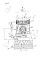
- the flow power plant 1 comprises a tower 2, which encloses a tube 3.
- a tower 2 which encloses a tube 3.
- the shell 4 of the tower 2 there are a plurality of openings 5, 6, namely at least one opening 5 in the lower third of the tube 3 and an opening 6 in the upper third of the tube 3, so that the medium within the tube 3, preferably air, freely circulate or can escape into the atmosphere.
- an updraft 7, ie the flow medium, in particular air, rises and thereby drives a helical or helical rotor 8, by means of a bearing assembly 9 about a vertical central axis 10 with about a constant velocity v M is rotationally mounted.
- the rotor 8 is connected via a mechanical hub or shaft 11 to the bearing assembly 9.
- the power plant 1 is perpendicular to a foundation or other, solid ground 12.
- Sensors 13 in the region of the openings 5, 6 are used to detect or calculate the flow rate of the medium.
- the flow power station 1 'after Fig. 2 has a standard rotor 8 'with two or more rotor blades 14 and a hub 15 along the vertical center axis 10'. Furthermore, it is possible to recognize a plurality of solar cells 16 spanning the tower shell 4 'which supply energy to an electrical converter or converter 17, for example for energizing a plurality of heating devices 18 in the lower third of the tube 3' or the tower 2 '. Through the media flow 7 'inside the tube 3', the bearing assembly 9 'is cooled during its rotary operation. By suitable wiring of a separate heating device 18, the bearing assembly 9 'during operation also be heated, for example when using the power plant 1 in cold or frosty regions. The power plant 1 'is perpendicular to a foundation or a solid ground 12' or on a plant platform.
- a plurality of coil elements 19 are provided as components of an integrated electric generator 20, wherein a coil element 19 is supplied via an electrical converter 21 with electrical energy for providing an electromagnetic field. Also shown are a plurality of rechargeable batteries or storage cells 22, preferably accommodated in reserve areas 23 in the foundation 12 ", and / or accommodated in one and the same housing together with an electrical converter 24. The latter converter 24 can supply a large-area heating device 18". Furthermore, a plurality of the tower shell 4 "spanning solar film elements 16" can be seen, and a converter 25 for the grid feed, with memory cells 22 and with electrical transducers or Converters 17 “, 24. Electric power plant 1" stands vertically on a ground foundation or on solid ground 12 ".
- the power plant 1 comprises a plurality of coil elements 19 (3) as a component of an integrated electric generator 20 (3) , wherein a coil element 19 (3) via an electrical converter 17 (3) or 24 (3) , ie directly or indirectly, is supplied with electrical energy for Provision of an electromagnetic field. Also shown are a plurality of separate, 3 in the lower region of the tube (3) installed heating elements 18 (3), which are each electrically connected to an electrical storage cell 22 (3). The plurality of heating elements 18 (3) are arranged so that they can deliver their heat or heating energy to the passing medium. The energization of the heating elements 18 (3) can be done either by the memory cell 22 (3) and / or by an electrical converter 24 (3) .
- a network coupling converter 25 ( Fig.
- the power plant 1 (3) is perpendicular to a foundation or solid ground 12 (3) or on a plant platform.
- the power plant 1 (4) after Fig. 5 also has the shape of a tube 3 (4) having tower 2 (4) with openings 5 (4) 6 (4) in the upper and lower third, as well as with a casing 4 (4) of narrowed cross-section A w in the central region, while the cross section widens up and down. Shown are a plurality of concentric to the vertical center axis 10 (4) of the tube 3 (4) arranged bearing assemblies 9 (4) , which in each case via hubs 15 (4) a plurality of standard rotors 8 (4) , each with a plurality of rotor blades 14 (4) . At the lower end of this rotor assembly 8 ( FIG.
- a gear assembly 26 is flanged, which translates and directs the rotary motion of the mechanical shaft 27 of the rotor assembly 8 ( FIG. 4) to the adjacent electrical generator assembly 20 ( FIG. 4) .
- Both the rotor assembly 8 ( FIG. 4) and the gear assembly 26 as well as the generator assembly 20 ( FIG. 4) are installed by means of a plurality of machine supports 28 inside the tube 3 ( FIG. 4) .
- a vertical media flow 7 (4) rotates the rotors 8 (4) .
- the generator assembly 20 ( FIG. 4) is electrically connected or coupled to an electrical converter or inverter 24 (FIG. 4) , which in turn is electrically connected to an electrical storage cell 22 (4) is connected as well as with the converter 25 (4) for the grid feed.
- the power plant 1 (5) after Fig. 6a and 6b only a large-area opening 6 (5) at the top of the tower 2 also has a a tube 3 (5) enclosing Tower 2 (5) having a plurality of openings 5 (5) in the lower third of the tower 2 (5), but (5 ) .
- the cross section A e of the tower 2 (5) is widened, while below this area directly adjoins a region with a minimum tower diameter d i , through which the medium flows at its greatest flow velocity v i .
- FIG. 5 Shown are a plurality of concentric to the vertical central axis 10 (5) oriented bearing assemblies 9 (5) respectively at the upper and lower end of a rotor assembly 8 (5) , which in each case via hubs 15 (5) a plurality of standard rotors 8 (5) each having a plurality Store rotor blades 14 (5) .
- a gear assembly 26 At the lower end of this rotor assembly 8 ( FIG. 5) is a gear assembly 26 (FIG. 5) which translates the rotational motion of the mechanical shaft 27 ( FIG. 5) and relays it to the adjacent electrical generator assembly 20 ( FIG. 5) .
- the mechanical shaft 27 (FIG. 5) extends along and in the direction of the vertical central axis 10 (FIG . 5) .
- Both the rotor assembly 8 (5) and the gear assembly 26 (5) as well as the generator assembly 20 (5) is supported on a tower 2 (5) in its entire length I r inside by withdrawing machine support 28 (5).
- the generator assembly 20 ( FIG. 5) is electrically coupled to an electrical converter or inverter 24 (FIG. 5) , which in turn is electrically connected to an electrical storage cell 22 ( FIG. 5) , as well as to the mains feed converter 25 ( FIG. 5) .
- the power plant 1 (6) after Fig. 7 comprises a tube 3 (6) in a stylized hourglass shape, with a cross-sectionally narrowed approximately in the central region silhouette.
- the region of minimum cross-section extends over a length l i in the upper and in the middle part of the tube 3 (6) .
- solar modules 16 (6) and / or solar module foil elements and / or photovoltaic elements or PV cells which encompass the casing 4 (6) in order to oppose as much as possible the surface of the sun and to absorb or absorb it.
- the power plant 1 (7) after Fig. 8a and 8b has a tube 3 (7) with a simple, round cross-section.
- the length l r of this tube 3 (7) is much larger than its diameter d i .
- the jacket 4 (7) is covered with solar modules 16 (7) and / or solar module film elements and / or photovoltaic elements and / or PV cells, which surround the jacket 4 (7) in an annular manner.
- the upper half of the drawing, Fig. 8b shows the plan view of the tube 3 (7) . It can be seen a large circular upper opening 6 (7) through which the flow medium, in particular air, from the interior of the tube 3 (7) can escape into the atmosphere 30.
- a flow and / or climate sensor 13 (7) At the upper end of the tube 3 (7) , a flow and / or climate sensor 13 (7) , for example. In the form of an anemometric sensor, installed to detect the wind currents at the upper part of the tube 3 (7) . Similarly, at the lower end of the tube 3 (7) ⁇ a flow and / or climate sensor 13 (7) is provided, also in the form of an anemometric sensor to detect the wind currents near the bottom or the foundation.
- the power plant 1 (8) after Fig. 9a and 9b has a tower 2 (8) with polygonal, in particular octagonal cross-section.
- the length I k of this tube 3 (8) is greater than each diameter d o , d u of this tube 3 (8) .
- a plurality of solar modules 16 (8) and / or solar module foil elements and / or photovoltaic elements or PV cells annularly surround the shell 4 (8) in order to absorb or absorb the solar radiation.
- the upper half of the drawing, 9b shows the plan view of the tower 2 (8) . It can be seen a polygonal upper opening 6 (8) , through which the flow medium, in particular air, from the interior of the tube 3 (8) in the atmosphere 30 (8) can escape.
- the ground 12 (8) or the foundation on which the tower 2 (8) is erected must be above the height mark HN which, when installing the power plant 1 (8) on the high seas or in flowing waters, under no circumstances from the underlying masses of water may be achieved.
- coil elements 19 (9) As a component of an integrated electric generator 20 (9) .
- These coil elements 19 (9) a distinction is made between the electromechanical stator part 31 and the electromechanical rotor part 32, the latter being the same as the rotor 33 in the generator 20 (9) .
- the coil elements 19 (9) of the stator part 31 are directly supplied with electrical energy via an electrical converter or converter 17 (9) , preferably for providing an electromagnetic field in the interior of the electrical generator 20 (9) .
- the tap of the induction generated in the interior of the generator 20 (9) electrical voltage via a contact, preferably on the rotor part 33 of the generator 20 (9) .
- the rotor 8 (9) which is set into rotary motion by the media flow 7 (9) , and which is coupled directly or indirectly to the rotor 33 of the generator 20 (9), is not shown.
- the electrical energy recovered by the generator 20 (FIG. 9) is transmitted to an electrical converter or inverter 22.
- Generator 20 (9) and converter 24 (9) are electrically coupled, for example by a line connection.
- the plurality of heating elements 18 (9) are arranged so that they can deliver their heat or heating energy to the passing flow medium.
- the energization of the heating elements 18 (9) can optionally be done by the memory cell 22 (9) and / or by an electrical converter or inverter 24 (9) .
- the mains supply is a converter 25 (9) , which is electrically connected both to the memory cell 22 (9) and to the electrical converters or converters 17 (9) , 24 (9) .
- the tower shell 4 (9) spanning solar modules 16 (9) or PV cells.
- One of the electrical converters or inverters 17 (FIG. 9) is electrically connected or coupled to these photovoltaic modules 16 ( FIG. 9) or PV cells.
- the energization of the above-mentioned coils 19 (9) is preferably carried out by the energy which is obtained from the solar radiation.
- the power plant 1 (9) is perpendicular to a piece of equipment 12 (9), or on a platform of a system component 12 (9). It may be a platform on a mobile system, such as a marine vehicle or a land vehicle.
Landscapes
- Engineering & Computer Science (AREA)
- Life Sciences & Earth Sciences (AREA)
- Sustainable Development (AREA)
- Sustainable Energy (AREA)
- Chemical & Material Sciences (AREA)
- Combustion & Propulsion (AREA)
- Mechanical Engineering (AREA)
- General Engineering & Computer Science (AREA)
- Power Engineering (AREA)
- Wind Motors (AREA)
Applications Claiming Priority (1)
| Application Number | Priority Date | Filing Date | Title |
|---|---|---|---|
| DE102012017706 | 2012-09-07 |
Publications (2)
| Publication Number | Publication Date |
|---|---|
| EP2706227A2 true EP2706227A2 (fr) | 2014-03-12 |
| EP2706227A3 EP2706227A3 (fr) | 2015-03-11 |
Family
ID=48875450
Family Applications (1)
| Application Number | Title | Priority Date | Filing Date |
|---|---|---|---|
| EP13003288.1A Withdrawn EP2706227A3 (fr) | 2012-09-07 | 2013-06-28 | Centrale hydromotrice pour l'utilisation d'un courant ascendant |
Country Status (1)
| Country | Link |
|---|---|
| EP (1) | EP2706227A3 (fr) |
Cited By (5)
| Publication number | Priority date | Publication date | Assignee | Title |
|---|---|---|---|---|
| CN109139399A (zh) * | 2018-09-13 | 2019-01-04 | 西安西热节能技术有限公司 | 一种废弃冷却塔光热风电综合利用系统及方法 |
| CN110173392A (zh) * | 2019-04-07 | 2019-08-27 | 上海九笙新材料科技有限公司 | 热动冷却发电塔 |
| DE102018127869A1 (de) * | 2018-06-01 | 2019-12-05 | Fabian Bruder | Vorrichtung zur Gewinnung von elektrischer Energie sowie entsprechendes Verfahren |
| US20230339585A1 (en) * | 2020-08-04 | 2023-10-26 | Norsepower Oy Ltd | A control method for a wind propulsion device on a vessel |
| US20240318627A1 (en) * | 2022-03-28 | 2024-09-26 | Green Power By Accelerated Flow Research Limited Liability Company | Vertical wind speed acceleration type wind turbine |
Citations (1)
| Publication number | Priority date | Publication date | Assignee | Title |
|---|---|---|---|---|
| DE4114501A1 (de) | 1991-05-03 | 1992-11-05 | Joergen Brosow | Kraftwerk |
Family Cites Families (6)
| Publication number | Priority date | Publication date | Assignee | Title |
|---|---|---|---|---|
| GB1519774A (en) * | 1975-10-28 | 1978-08-02 | Patten R | Apparatus for the generation of power from naturally available energy |
| JPS5946374A (ja) * | 1982-09-10 | 1984-03-15 | Makoto Minamidate | 風力発電装置 |
| ITPC20040016A1 (it) * | 2004-04-19 | 2004-07-19 | Angelo Comandu | Impianto per la produzione di energia dal vento e relativo procedimento. |
| US20090152370A1 (en) * | 2007-12-18 | 2009-06-18 | Michael Gregory Pesochinsky | Chimney device and methods of using it to fight global warming, produce water precipitation and produce electricity |
| DE102008013141A1 (de) * | 2008-03-07 | 2009-09-10 | Deutsches Zentrum für Luft- und Raumfahrt e.V. | Wirbelströmungskraftwerk |
| TW201142146A (en) * | 2010-05-28 | 2011-12-01 | Epoch Energy Technology Corp | Compound-type electric power generation system |
-
2013
- 2013-06-28 EP EP13003288.1A patent/EP2706227A3/fr not_active Withdrawn
Patent Citations (1)
| Publication number | Priority date | Publication date | Assignee | Title |
|---|---|---|---|---|
| DE4114501A1 (de) | 1991-05-03 | 1992-11-05 | Joergen Brosow | Kraftwerk |
Cited By (6)
| Publication number | Priority date | Publication date | Assignee | Title |
|---|---|---|---|---|
| DE102018127869A1 (de) * | 2018-06-01 | 2019-12-05 | Fabian Bruder | Vorrichtung zur Gewinnung von elektrischer Energie sowie entsprechendes Verfahren |
| DE102018127869B4 (de) | 2018-06-01 | 2023-02-02 | Fabian Bruder | Vorrichtung zur Gewinnung von elektrischer Energie sowie entsprechendes Verfahren |
| CN109139399A (zh) * | 2018-09-13 | 2019-01-04 | 西安西热节能技术有限公司 | 一种废弃冷却塔光热风电综合利用系统及方法 |
| CN110173392A (zh) * | 2019-04-07 | 2019-08-27 | 上海九笙新材料科技有限公司 | 热动冷却发电塔 |
| US20230339585A1 (en) * | 2020-08-04 | 2023-10-26 | Norsepower Oy Ltd | A control method for a wind propulsion device on a vessel |
| US20240318627A1 (en) * | 2022-03-28 | 2024-09-26 | Green Power By Accelerated Flow Research Limited Liability Company | Vertical wind speed acceleration type wind turbine |
Also Published As
| Publication number | Publication date |
|---|---|
| EP2706227A3 (fr) | 2015-03-11 |
Similar Documents
| Publication | Publication Date | Title |
|---|---|---|
| US8257019B2 (en) | Shrouded wind turbine system with yaw control | |
| US8210817B2 (en) | Wind turbine utilizing wind directing slats | |
| US20090074577A1 (en) | Vertical axis sail-type windmill power transfer device | |
| US20120061968A1 (en) | Burrell compound axial windmill | |
| WO2014082653A1 (fr) | Dispositif d'asservissement équipé d'une structure de réception déplaçable sur un ou plusieurs axes et destinée au montage d'un ou plusieurs éléments sensibles aux ondes électromagnétiques et présentant une direction de rayonnement préférentielle | |
| EP2706227A2 (fr) | Centrale hydromotrice pour l'utilisation d'un courant ascendant | |
| WO2011129859A2 (fr) | Éolienne utilisant des volets déflecteurs de vent | |
| EP2914844B1 (fr) | Procédé pour faire fonctionner une éolienne, éolienne et dispositif de commande pour une éolienne | |
| Vignesh et al. | Design and fabrication of vertical axis wind mill with solar system | |
| DE202012009612U1 (de) | Elektrostatische Windenergieanlage mit Mini-Rotoren | |
| WO2009127636A2 (fr) | Centrale à courant ascendant | |
| Badawi | An analytical study for establishment of wind farms in palestine to reach the optimum electrical energy | |
| DE102012017707A1 (de) | Energieröhrenkraftwerk | |
| EP1626176A2 (fr) | Eolienne comprenant un convertisseur solaire | |
| Gawad | New, simple blade-pitch control mechanism for small-size, horizontal-axis wind turbines | |
| Rao | Wind energy: Technical considerations–contents | |
| DE3300049A1 (de) | Windkreisel, ein windenergiekonverter mit vertikaler achse fuer alle groessen bis in den 100 mw-bereich | |
| EP4361435A1 (fr) | Eolienne a axe vertical | |
| JP5065535B1 (ja) | 太陽光風力発電装置 | |
| DE102010013141B4 (de) | Kollektorfeld mit Solarmodulen | |
| DE102010006336A1 (de) | Windkraftanlage | |
| RS20160989A2 (sr) | Solarna vetrenjača | |
| EP3798435A1 (fr) | Unité de centrale électrique pour une centrale électrique hybride | |
| DE102017110698B4 (de) | Windkraftwerk und Verfahren zum Betreiben eines Windkraftwerks | |
| DE102023001394B4 (de) | Windkraftanlage auf Basis Unterdruck nach Bernoulli |
Legal Events
| Date | Code | Title | Description |
|---|---|---|---|
| PUAI | Public reference made under article 153(3) epc to a published international application that has entered the european phase |
Free format text: ORIGINAL CODE: 0009012 |
|
| AK | Designated contracting states |
Kind code of ref document: A2 Designated state(s): AL AT BE BG CH CY CZ DE DK EE ES FI FR GB GR HR HU IE IS IT LI LT LU LV MC MK MT NL NO PL PT RO RS SE SI SK SM TR |
|
| AX | Request for extension of the european patent |
Extension state: BA ME |
|
| PUAL | Search report despatched |
Free format text: ORIGINAL CODE: 0009013 |
|
| AK | Designated contracting states |
Kind code of ref document: A3 Designated state(s): AL AT BE BG CH CY CZ DE DK EE ES FI FR GB GR HR HU IE IS IT LI LT LU LV MC MK MT NL NO PL PT RO RS SE SI SK SM TR |
|
| AX | Request for extension of the european patent |
Extension state: BA ME |
|
| RIC1 | Information provided on ipc code assigned before grant |
Ipc: F03D 3/04 20060101ALI20150130BHEP Ipc: F03D 1/04 20060101AFI20150130BHEP Ipc: F03D 9/00 20060101ALI20150130BHEP |
|
| STAA | Information on the status of an ep patent application or granted ep patent |
Free format text: STATUS: THE APPLICATION IS DEEMED TO BE WITHDRAWN |
|
| 18D | Application deemed to be withdrawn |
Effective date: 20150912 |