EP2706236B1 - Pumpe mit Trockenlaufschutz - Google Patents
Pumpe mit Trockenlaufschutz Download PDFInfo
- Publication number
- EP2706236B1 EP2706236B1 EP13180049.2A EP13180049A EP2706236B1 EP 2706236 B1 EP2706236 B1 EP 2706236B1 EP 13180049 A EP13180049 A EP 13180049A EP 2706236 B1 EP2706236 B1 EP 2706236B1
- Authority
- EP
- European Patent Office
- Prior art keywords
- pump
- mechanical seal
- seal arrangement
- rear wall
- pump housing
- Prior art date
- Legal status (The legal status is an assumption and is not a legal conclusion. Google has not performed a legal analysis and makes no representation as to the accuracy of the status listed.)
- Active
Links
Images

Classifications
-
- F—MECHANICAL ENGINEERING; LIGHTING; HEATING; WEAPONS; BLASTING
- F04—POSITIVE - DISPLACEMENT MACHINES FOR LIQUIDS; PUMPS FOR LIQUIDS OR ELASTIC FLUIDS
- F04D—NON-POSITIVE-DISPLACEMENT PUMPS
- F04D15/00—Control, e.g. regulation, of pumps, pumping installations or systems
- F04D15/0077—Safety measures
-
- F—MECHANICAL ENGINEERING; LIGHTING; HEATING; WEAPONS; BLASTING
- F04—POSITIVE - DISPLACEMENT MACHINES FOR LIQUIDS; PUMPS FOR LIQUIDS OR ELASTIC FLUIDS
- F04D—NON-POSITIVE-DISPLACEMENT PUMPS
- F04D29/00—Details, component parts, or accessories
- F04D29/08—Sealings
- F04D29/10—Shaft sealings
- F04D29/106—Shaft sealings especially adapted for liquid pumps
-
- F—MECHANICAL ENGINEERING; LIGHTING; HEATING; WEAPONS; BLASTING
- F04—POSITIVE - DISPLACEMENT MACHINES FOR LIQUIDS; PUMPS FOR LIQUIDS OR ELASTIC FLUIDS
- F04D—NON-POSITIVE-DISPLACEMENT PUMPS
- F04D29/00—Details, component parts, or accessories
- F04D29/06—Lubrication
- F04D29/061—Lubrication especially adapted for liquid pumps
-
- F—MECHANICAL ENGINEERING; LIGHTING; HEATING; WEAPONS; BLASTING
- F04—POSITIVE - DISPLACEMENT MACHINES FOR LIQUIDS; PUMPS FOR LIQUIDS OR ELASTIC FLUIDS
- F04D—NON-POSITIVE-DISPLACEMENT PUMPS
- F04D29/00—Details, component parts, or accessories
- F04D29/08—Sealings
- F04D29/10—Shaft sealings
- F04D29/12—Shaft sealings using sealing-rings
- F04D29/126—Shaft sealings using sealing-rings especially adapted for liquid pumps
-
- F—MECHANICAL ENGINEERING; LIGHTING; HEATING; WEAPONS; BLASTING
- F04—POSITIVE - DISPLACEMENT MACHINES FOR LIQUIDS; PUMPS FOR LIQUIDS OR ELASTIC FLUIDS
- F04D—NON-POSITIVE-DISPLACEMENT PUMPS
- F04D29/00—Details, component parts, or accessories
- F04D29/40—Casings; Connections of working fluid
- F04D29/42—Casings; Connections of working fluid for radial or helico-centrifugal pumps
- F04D29/426—Casings; Connections of working fluid for radial or helico-centrifugal pumps especially adapted for liquid pumps
- F04D29/4286—Casings; Connections of working fluid for radial or helico-centrifugal pumps especially adapted for liquid pumps inside lining, e.g. rubber
-
- F—MECHANICAL ENGINEERING; LIGHTING; HEATING; WEAPONS; BLASTING
- F05—INDEXING SCHEMES RELATING TO ENGINES OR PUMPS IN VARIOUS SUBCLASSES OF CLASSES F01-F04
- F05D—INDEXING SCHEME FOR ASPECTS RELATING TO NON-POSITIVE-DISPLACEMENT MACHINES OR ENGINES, GAS-TURBINES OR JET-PROPULSION PLANTS
- F05D2260/00—Function
- F05D2260/95—Preventing corrosion
Definitions
- the invention relates to a pump, in particular a centrifugal pump according to claim 1.
- Such a pump comprises a pump housing with an inlet and an outlet, a motor shaft, which is connected in a rotationally fixed manner to an impeller arranged in the pump housing, is rotatably mounted in a rear wall of the pump housing with a primary mechanical seal arrangement, the primary mechanical seal arrangement being associated with a dry-running protection system.
- Centrifugal pumps are used in particular to pump liquid pump media, such as swimming pool water.
- the pump medium is sucked in at the inlet and discharged under pressure at the outlet.
- an impeller is rotatably arranged in the pump housing for this purpose, which is connected to a motor via a motor shaft and is set in rotation by the latter.
- An essentially radial flow is generated in the pump medium, whereby a pressure within the pump is increased and the pump medium is pressed out of the outlet.
- the motor shaft is usually mounted in the pump housing or in the rear wall of the pump housing via a mechanical seal arrangement which comprises a slide ring and a counter ring, the slide ring being connected in a stationary manner in the pump housing and the counter ring being connected in a stationary manner to the motor shaft.
- a mechanical seal arrangement which comprises a slide ring and a counter ring, the slide ring being connected in a stationary manner in the pump housing and the counter ring being connected in a stationary manner to the motor shaft.
- the slide ring and the counter ring slide against each other.
- an additional sealing ring can be provided between the slide ring and the counter ring.
- the mechanical seal arrangement In order to keep friction losses low and to prevent an additional temperature from being exceeded, the mechanical seal arrangement must be cooled or lubricated. This lubrication is usually done by the pump medium that wets the mechanical seal assembly. Since an inside surface of the mechanical seal arrangement is generally connected to a pressure chamber of the pump, the pump medium can come into contact with the mechanical seal arrangement. It is also known to direct the pump medium under pressure through special channels to the mechanical seal arrangement.
- Such dry run protection represents passive protection that works relatively reliably. However, when a fault is detected, the pump is always switched off, which can result in longer downtimes and thus increases maintenance costs. Stopping the pumps completely is also problematic in many applications, so that the area of use of such dry-running protection is limited.
- the EP 1 222 393 A1 discloses the preamble of claim 1.
- the JP 2004 245134A , U.S. 3,741,679 A , US 6 422 822 B1 and GB 2 078 878 A disclose other relevant pumps.
- the invention is based on the object of eliminating the disadvantages of the prior art and, in particular, of specifying a pump which has high operational reliability and requires little maintenance.
- the dry-running protection system thus has a liquid volume which is connected to a side of the primary mechanical seal arrangement facing away from the impeller. This can be achieved by the liquid volume directly adjoining an outside of the primary mechanical seal arrangement.
- the liquid volume can be filled with white oil or another liquid, for example. This liquid lubricates and cools the primary mechanical seal assembly when lubrication by the pump medium is interrupted. This reliably prevents inadmissible heating of the mechanical seal arrangement. This ensures that the slide ring and the counter ring always slide on a thin film.
- This provides active protection of the mechanical seal arrangement by the dry-running protection system, with emergency running lubrication being obtained, so that switching off the pump if the primary mechanical seal arrangement is not lubricated by the pump medium does not have to result in the pump being switched off. Rather, the primary mechanical seal arrangement is protected from temperature-related failures by the liquid in the liquid volume.
- the volume of liquid prevents the pump medium from penetrating into the drive of the pump in the event of a leak in the mechanical seal arrangement. Rather, the pump medium is then stopped in the liquid volume.
- the dry running protection system reduces downtimes of the pump and increases operational safety. This provides active protection that enables the pump to continue operating even if the lubrication from the pump medium is insufficient. Overall, this results in a very low-maintenance, safe operation of the pump with a low probability of failure.
- the liquid volume is formed between the rear wall of the pump and a cover of the pump housing.
- the liquid volume is thus formed by a chamber which is formed between the rear wall and the lid. If necessary, a modified standard rear wall can be used to provide sufficient volume deliver. The dry-running protection system can then be implemented with relatively little effort.
- the motor shaft is rotatably mounted in the cover with a secondary mechanical seal arrangement. This mechanical seal arrangement is then also cooled by the liquid in the liquid volume.
- a particularly simple embodiment is achieved in that the cover is connected to the rear wall in a fluid-tight manner, in particular is screwed or jammed or pressed. If necessary, an additional sealant can be provided between the cover and the rear wall in order to securely seal the liquid volume to the outside.
- a screw connection between the cover and the rear wall has the advantage that the cover can be removed with relatively little effort, for example to carry out maintenance work.
- the dry-running protection system has a storage container which is connected to the liquid volume by an access formed in the pump housing, in particular in the rear wall.
- the storage container is therefore arranged outside the pump housing and connected to the access via lines.
- the storage container is used on the one hand to store a sufficient amount of liquid so that a complete filling of the liquid volume is always guaranteed and on the other hand it is used as a pressure compensation vessel so that, for example, heating of the liquid in the liquid volume with the resulting increase in volume is problem-free.
- the storage container is arranged geodetically higher than the primary mechanical seal arrangement. On the one hand, this results in automatic replenishment of the liquid volume and, on the other hand, it ensures that the mechanical seal arrangement is always covered by the liquid in the liquid volume.
- An outlet of the storage container should be formed at a location of the storage container that is as geodetically as deep as possible, so that all the liquid present in the storage container can, if appropriate, be transferred into the liquid volume.
- the storage container is connected to the access via 90 ° angled lines, which have sufficient mechanical stability to support the storage container. The overall structure is kept simple.
- a fill level of the storage container can preferably be monitored. When the liquid in the reservoir rises, a signal can then be output. Leakage can thus be recognized relatively quickly.
- the storage container is at least partially transparent. A level of the liquid in the storage container is then relatively easy to see with the naked eye. A check of the dry-running protection system is therefore possible with little effort. A transparent design of the storage container is easily possible, for example, by choosing an appropriate material, such as glass or plastic.
- the pump housing has a venting device for venting a pressure chamber.
- the pressure chamber is located between the rear wall and the impeller. Air in the pressure chamber can lead to a disturbance in the lubrication of the mechanical seal arrangement by the pump medium. Accordingly, it is favorable if the air can escape from the pump.
- the ventilation device can have, for example, a ventilation screw or a ventilation valve that is operated manually or automatically.
- the pump housing is made of gray cast iron.
- the pump can thus be manufactured very inexpensively.
- the pump housing can have a corrosion-resistant coating to prevent corrosion of the pump housing.
- FIG. 1 a centrifugal pump 1 with a pump housing 2 is shown in a spatial representation.
- the pump housing 2 has an inlet 3 and an outlet 4 for a pump medium, especially for liquids.
- the pump housing 2 is designed in several parts and has, among other things, a rear wall 5, which seals a pressure chamber, and a cover 6, which is fastened to the rear wall 5.
- a motor 7 is fixed, which is used to drive an impeller of the pump.
- a reservoir 10 is connected to the pressure chamber of the pump 1 via an access 8 and a line 9, the access being formed in one piece with the rear wall 5.
- the storage container 10 is formed from a transparent material such as glass, so that the level of a liquid in the storage container 10 can be seen from the outside.
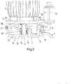
- the storage container 10 is part of a dry protection running system that in connection with Figure 2 is explained in more detail, which shows a detail of the pump 1.
- the motor 7 is rotatably connected to an impeller 12 via a motor shaft 11 and can set the impeller 12 in rotation.
- a pump medium is acted upon essentially in the radial direction, so that a radial flow is formed and the pump medium is sucked in at the inlet 3 and is released under pressure at the outlet 4. Accordingly, there is a pressure chamber 13 between the impeller 12 and the rear wall 5.
- the motor shaft 11 is mounted in the rear wall 5 with a primary mechanical seal arrangement 14, which comprises at least one slide ring 15, 23 and a counter ring 16.
- the mechanical seal arrangement 14 serves on the one hand to mount the motor shaft 11 in the rear wall 5 and on the other hand to seal the pressure chamber 13.
- the pump medium located in the pressure chamber 13 serves to lubricate the mechanical seal arrangement 14, so that normally a thin film of pump medium is between the slide ring 15, 23 and the counter ring 16 is formed.
- a liquid volume 17 is formed, in which a lubricating liquid such as white oil is received.
- the liquid volume 17 takes up a space between the rear wall 5 and the cover 6, which are connected to one another in a fluid-tight manner.
- a seal 18 is arranged between the cover 6 and the rear wall 5 and the cover 6 is fastened by means of screws 19.
- the motor shaft 11 is mounted in the cover 6 via a secondary mechanical seal arrangement 20.
- the secondary mechanical seal arrangement 20 seals the passage of the motor shaft 6 from the liquid volume 17.
- the liquid volume 17 should always be filled as completely as possible with liquid in order not only to be in contact with the primary mechanical seal arrangement 14, but also with the secondary mechanical seal arrangement 20.
- the liquid volume 17 is connected to the reservoir 10, which is geodetically is arranged higher than the primary mechanical seal arrangement 14 and the secondary mechanical seal arrangement 20, so that in particular as long as there is liquid in the reservoir 10, it is always ensured that the primary mechanical seal arrangement 14 and the secondary mechanical seal arrangement 20 are covered by the liquid in the liquid volume 17 .
- the storage container 10 also serves as a pressure compensation container, which can compensate, for example, temperature-related fluctuations in the liquid.
- the liquid in the liquid volume 17 takes on several tasks. On the one hand, it ensures adequate cooling and lubrication of the primary mechanical seal arrangement 14 if the lubrication is interrupted by the pump medium. On the other hand, escape of the pump medium in the area of the mechanical seal arrangement 14 is prevented. This increases the operational reliability of the pump. In particular, dry running of the primary mechanical seal arrangement 14 is reliably avoided and continued operation of the pump is made possible even if adequate lubrication by the pump medium is not guaranteed.
- the liquid in the liquid volume can also lubricate and cool the secondary mechanical seal 20.
- a venting device 21 is provided in the pump housing 2, which is arranged at the geodetically highest point of the pressure chamber 13 and enables the pressure chamber 13 to be vented manually.
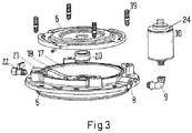
- FIG. 3 shows the essential elements of the dry-running protection system in an exploded view.
- the cover 6 is provided in order to be able to form the liquid volume 17 between the rear wall 5 and the cover 6.
- the rear wall 5 is additionally shaped so that a chamber of sufficient size is created for the absorption of the liquid.
- the cover 6 can be screwed to the rear wall 5 in a fluid-tight manner by means of the screws 19.
- the motor shaft 11 is mounted in the cover 6 with a secondary mechanical seal arrangement 20.
- the liquid volume 17 is connected via the access 8 and the line 9 to the reservoir 10, from which liquid is automatically refilled.
- the storage container can have an atmospheric connection 24, for example a hole.
- a vent device 21 with a vent screw 22 is formed in the rear wall 5.
- a pump is thus provided which offers high operational reliability with low maintenance requirements and is less prone to failure. This provides additional protection against the escape of pump media.
- the pump housing can be provided with an additional coating, which is particularly useful if the pump housing is made of gray cast iron.
Landscapes
- Engineering & Computer Science (AREA)
- Mechanical Engineering (AREA)
- General Engineering & Computer Science (AREA)
- Structures Of Non-Positive Displacement Pumps (AREA)
Description
- Die Erfindung betrifft eine Pumpe, insbesondere Kreiselpumpe gemäß Anspruch 1.
- Eine derartige Pumpe umfasst ein Pumpengehäuse mit einem Einlass und einem Auslass, wobei eine Motorwelle, die mit einem im Pumpengehäuse angeordneten Laufrad drehfest verbunden ist, in einer Rückwand des Pumpengehäuses mit einer primären Gleitringdichtungsanordnung drehbar gelagert ist, wobei der primären Gleitringdichtungsanordnung ein Trockenlaufschutzsystem zugeordnet ist.
- Kreiselpumpen dienen insbesondere zur Förderung flüssiger Pumpenmedien, wie beispielsweise Schwimmbadwasser. Dabei wird das Pumpenmedium am Einlass angesaugt und am Auslass unter Druck ausgegeben. Bei Kreiselpumpen ist dafür ein Laufrad drehbar im Pumpengehäuse angeordnet, dass über eine Motorwelle mit einem Motor verbunden ist und durch diesen in Drehbewegung versetzt wird. Dabei wird in dem Pumpenmedium eine im Wesentlichen radiale Strömung erzeugt, wodurch ein Druck innerhalb der Pumpe erhöht wird und das Pumpenmedium aus dem Auslass herausgedrückt wird.
- Die Lagerung der Motorwelle im Pumpengehäuse bzw. in der Rückwand des Pumpengehäuses erfolgt in der Regel über eine Gleitringdichtungsanordnung, die einen Gleitring und einen Gegenring umfasst, wobei der Gleitring stationär im Pumpengehäuse und der Gegenring stationär mit der Motorwelle verbunden ist. Bei einer Drehung der Motorwelle gleiten der Gleitring und der Gegenring dann aneinander. Zur Erhöhung der Dichtigkeit kann ein zusätzlicher Dichtring zwischen Gleitring und Gegenring vorgesehen sein.
- Um Reibungsverluste klein zu halten und eine Überschreitung einer zusätzlichen Temperatur zu verhindern, muss die Gleitringdichtungsanordnung gekühlt bzw. geschmiert werden. Diese Schmierung erfolgt in der Regel durch das Pumpenmedium, das die Gleitringdichtungsanordnung benetzt. Da eine innenseitige Fläche der Gleitringdichtungsanordnung in der Regel mit einem Druckraum der Pumpe in Verbindung steht, kann das Pumpenmedium in Kontakt mit der Gleitringdichtungsanordnung gelangen. Es ist auch bekannt, dass unter Druck stehende Pumpenmedium durch spezielle Kanäle gezielt an die Gleitringdichtungsanordnung heran zu leiten.
- Bei diesem Vorgehen kann ein Trockenlaufen der Gleitringdichtungsanordnung nicht vollständig verhindert werden. Dabei bildet sich eine Luftblase um die Gleitringdichtungsanordnung, die ein Kühlen und Schmieren zwischen Gleitring und Gegenring durch das Pumpenmedium verhindert. Dies kann zu einer Überhitzung und schließlich zum Ausfall der Gleitringdichtungsanordnung führen. Die Gleitringdichtungsanordnung ist dann nicht mehr in der Lage, das Pumpengehäuse ausreichend abzudichten. Dabei kann Pumpenmedium aus dem Druckraum durch die Gleitringdichtungsanordnung austreten.
- Aus
DE 20 313 289 U1 ist ein Trockenlaufschutz für eine Pumpe bekannt, wobei ein Füllstand des Pumpenmediums innerhalb des Pumpengehäuses mit einem Fluiddetektor überwacht wird. Dabei wird sichergestellt, dass ein Betrieb der Pumpe nur dann möglich ist, wenn die Gleitringdichtungsanordnung von Pumpenmedium umspült ist. Dafür ist ein zusätzlicher Umführungskanal vorgesehen. - Ein derartiger Trockenlaufschutz stellt einen passiven Schutz dar, der relativ zuverlässig arbeitet. Allerdings erfolgt bei Erkennen eines Fehlers immer ein Ausschalten der Pumpe, was längere Stillstandszeiten zur Folge haben kann und damit einen erhöhten Wartungsaufwand nach sich zieht. Ein vollständiges Stoppen der Pumpen ist bei vielen Anwendungen auch problematisch, so dass der Einsatzbereich eines derartigen Trockenlaufschutzes beschränkt ist.
- Die
EP 1 222 393 A1 offenbart den Oberbegriff von Anspruch 1. DieJP 2004 245134A US 3 741 679 A ,US 6 422 822 B1 undGB 2 078 878 A - Der Erfindung liegt nun die Aufgabe zu Grunde, die Nachteile des Stands der Technik zu beheben und insbesondere eine Pumpe anzugeben, die eine hohe Betriebssicherheit aufweist und einen geringen Wartungsaufwand erfordert.
- Diese Aufgabe wird durch eine Pumpe mit den Merkmalen des Anspruchs 1 gelöst. Ausgestaltungen sind Gegenstand der Ansprüche 2 bis 6.
- Das Trockenlaufschutzsystem weist also ein Flüssigkeitsvolumen auf, das mit einer vom Laufrad abgewandten Seite der primären Gleitringdichtungsanordnung in Verbindung steht. Dies kann dadurch erreicht werden, dass das Flüssigkeitsvolumen direkt an eine Außenseite der primären Gleitringdichtungsanordnung angrenzt. Das Flüssigkeitsvolumen kann beispielsweise mit Weißöl oder einer anderen Flüssigkeit gefüllt sein. Durch diese Flüssigkeit erfolgt ein Schmieren und Kühlen der primären Gleitringdichtungsanordnung, wenn eine Schmierung durch das Pumpenmedium unterbrochen ist. Dadurch wird eine unzulässige Erhitzung der Gleitringdichtungsanordnung zuverlässig verhindert. Dabei wird sichergestellt, dass der Gleitring und der Gegenring immer auf einem dünnen Film gleiten. Damit erfolgt ein aktiver Schutz der Gleitringdichtungsanordnung durch das Trockenlaufschutzsystem, wobei eine Notlaufschmierung erhalten wird, so dass ein Abschalten der Pumpe bei Ausbleiben der Schmierung der primären Gleitringdichtungsanordnung durch das Pumpenmedium nicht zu einem Abschalten der Pumpe führen muss. Vielmehr ist die primäre Gleitringdichtungsanordnung durch die im Flüssigkeitsvolumen befindliche Flüssigkeit vor Temperatur bedingten Ausfällen geschützt.
- Darüber hinaus verhindert das Flüssigkeitsvolumen, das im Falle einer Undichtigkeit der Gleitringdichtungsanordnung das Pumpenmedium in den Antrieb der Pumpe eindringen kann. Vielmehr wird das Pumpenmedium dann im Flüssigkeitsvolumen aufgehalten. Durch das Trockenlaufschutzsystem werden also Stillstandszeiten der Pumpe verringert und eine Betriebssicherheit erhöht. Dabei wird ein aktiver Schutz bereitgestellt, der einen Weiterbetrieb der Pumpe auch dann ermöglicht, wenn die Schmierung durch das Pumpenmedium nicht ausreichend ist. Insgesamt ergibt sich damit ein sehr wartungsarmer, sicherer Betrieb der Pumpe mit einer geringen Ausfallwahrscheinlichkeit.
- Erfindungsgemäß ist das Flüssigkeitsvolumen zwischen der Pumpen-Rückwand und einem Deckel des Pumpengehäuses ausgebildet. Das Flüssigkeitsvolumen wird also durch eine Kammer gebildet, die zwischen der Rückwand und dem Deckel ausgebildet ist. Dabei kann gegebenenfalls eine modifizierte Standardrückwand verwendet werden, um ausreichend Volumen zur Verfügung zu stellen. Das Trockenlaufschutzsystem ist dann mit relativ geringem Aufwand zu realisieren.
- Dabei ist besonders bevorzugt, dass die Motorwelle mit einer sekundären Gleitringdichtungsanordnung drehbar im Deckel gelagert ist. Diese Gleitringdichtungsanordnung wird dann ebenfalls durch die Flüssigkeit im Flüssigkeitsvolumen gekühlt.
- Eine besonders einfache Ausgestaltung wird dadurch erreicht, dass der Deckel fluiddicht mit der Rückwand verbunden ist, insbesondere verschraubt oder verklemmt bzw. verpresst ist. Gegebenenfalls kann zwischen dem Deckel und der Rückwand ein zusätzliches Dichtmittel vorgesehen sein, um das Flüssigkeitsvolumen sicher nach außen abzudichten. Eine Verschraubung zwischen dem Deckel und der Rückwand hat dabei den Vorteil, dass der Deckel mit relativ geringem Aufwand entfernt werden kann, um beispielsweise Wartungsarbeiten durchzuführen.
- Erfindungsgemäß weist das Trockenlaufschutzsystem einen Vorratsbehälter auf, der durch einen im Pumpengehäuse, insbesondere in der Rückwand, ausgebildeten Zugang mit dem Flüssigkeitsvolumen verbunden ist. Der Vorratsbehälter ist also außerhalb des Pumpengehäuses angeordnet und über Leitungen an dem Zugang angeschlossen. Der Vorratsbehälter wird dabei zum einen zur Bevorratung einer ausreichenden Menge an Flüssigkeit verwendet, so dass immer eine vollständige Füllung des Flüssigkeitsvolumens gewährleistet ist und zum anderen als Druckausgleichsgefäß eingesetzt, so dass beispielsweise eine Erwärmung der Flüssigkeit im Flüssigkeitsvolumen mit dadurch entstehender Volumenzunahme problemlos ist.
- Erfindungsgemäß ist der Vorratsbehälter geodätisch höher angeordnet als die primäre Gleitringdichtungsanordnung. Dadurch erfolgt zum einen eine automatische Nachspeisung des Flüssigkeitsvolumens und zum anderen wird damit sichergestellt, dass die Gleitringdichtungsanordnung immer durch die im Flüssigkeitsvolumen befindliche Flüssigkeit bedeckt ist. Ein Auslass des Vorratsbehälters sollte dabei an einer geodätisch möglichst tiefen Stelle des Vorratsbehälters ausgebildet sein, so dass alle im Vorratsbehälter vorhandene Flüssigkeit gegebenenfalls in das Flüssigkeitsvolumen überführt werden kann. Um eine vertikale und horizontale Anordnung der Pumpe dabei zu ermöglichen, ist der Vorratsbehälter erfindungsgemäß über 90° gewinkelte Leitungen mit dem Zugang verbunden, die eine ausreichende mechanische Stabilität aufweisen, um den Vorratsbehälter zu tragen. Der Gesamtaufbau wird damit einfach gehalten.
- Vorzugsweise ist ein Füllstand des Vorratsbehälters überwachbar. Bei einem Ansteigen der Flüssigkeit im Vorratsbehälter kann dann ein Signal ausgegeben werden. Damit ist eine Leckage relativ schnell erkennbar.
- Eine vorteilhafte Ausgestaltung sieht dafür vor, dass der Vorratsbehälter zumindest teilweise transparent ist. Ein Stand der Flüssigkeit im Vorratsbehälter ist dann relativ einfach mit bloßem Auge erkennbar. Eine Überprüfung des Trockenlaufschutzsystems ist damit mit geringem Aufwand möglich. Eine transparente Ausgestaltung des Vorratsbehälters ist beispielsweise durch eine entsprechende Materialwahl wie Glas oder Kunststoff problemlos möglich.
- Zur Verbesserung der Betriebssicherheit ist erfindungsgemäß vorgesehen, dass das Pumpengehäuse eine Entlüftungsvorrichtung zum Entlüften eines Druckraums aufweist. Der Druckraum befindet sich zwischen Rückwand und Laufrad. Im Druckraum befindliche Luft kann zu einer Störung der Schmierung der Gleitringdichtungsanordnung durch das Pumpenmedium folgen. Dementsprechend ist es günstig, wenn die Luft aus der Pumpe entweichen kann. Dafür kann die Entlüftungsvorrichtung beispielsweise eine Entlüftungsschraube oder ein Entlüftungsventil aufweisen, das manuell oder automatisch bedient wird.
- In einer bevorzugten Ausführungsform ist das Pumpengehäuse aus Grauguss hergestellt. Die Pumpe ist damit sehr kostengünstig herstellbar. Für den Einsatz mit korrosiven Flüssigkeiten kann das Pumpengehäuse dabei eine korrosionsfeste Beschichtung aufweisen, um eine Korrosion des Pumpengehäuses zu verhindern.
- Weitere Vorteile der Erfindung, deren Schutzumfang ausschließlich durch die nachfolgenden Ansprüche bestimmt ist, ergeben sich aus der folgenden Beschreibung von Ausführungsbeispielen anhand der Zeichnungen. Es zeigen:
-
Figur 1 : eine Pumpe in räumlicher Darstellung, -
Figur 2 : einen Ausschnitt der Pumpe in teilgeschnittener Ansicht und -
Figur 3 : Komponenten eines Trockenlaufschutzsystems. - In
Figur 1 ist eine Kreiselpumpe 1 mit einem Pumpengehäuse 2 in räumlicher Darstellung gezeigt. Das Pumpengehäuse 2 weist einen Einlass 3 und einen Auslass 4 für ein Pumpenmedium, insbesondere für Flüssigkeiten auf. Das Pumpengehäuse 2 ist mehrteilig ausgeführt und weist unter anderem eine Rückwand 5, die einen Druckraum abdichtet, und einen Deckel 6 auf, der an der Rückwand 5 befestigt ist. Am Deckel 6 ist ein Motor 7 festgelegt, der zum Antrieb eines Laufrades der Pumpe dient. - Über einen Zugang 8 und eine Leitung 9 ist ein Vorratsbehälter 10 mit dem Druckraum der Pumpe 1 verbunden, wobei der Zugang einstückig mit der Rückwand 5 ausgebildet ist. Der Vorratsbehälter 10 ist aus einem durchsichtigen Material wie Glas gebildet, so dass der Stand einer Flüssigkeit im Vorratsbehälter 10 von außen erkennbar ist.
- Der Vorratsbehälter 10 ist Teil eines Trockenschutzlaufsystems, dass im Zusammenhang mit
Figur 2 näher erläutert wird, die einen Detailausschnitt der Pumpe 1 zeigt. Der Motor 7 ist über eine Motorwelle 11 mit einem Laufrad 12 drehfest verbunden und kann das Laufrad 12 in Rotation versetzen. Dadurch wird ein Pumpenmedium im Wesentlichen in radialer Richtung beaufschlagt, so dass sich eine radiale Strömung ausbildet und das Pumpenmedium am Einlass 3 eingesaugt wird und am Auslass 4 unter Druck herausgegeben wird. Dementsprechend befindet sich zwischen dem Laufrad 12 und der Rückwand 5 ein Druckraum 13. - Die Motorwelle 11 ist in der Rückwand 5 mit einer primären Gleitringdichtungsanordnung 14 gelagert, die mindestens einen Gleitring 15, 23 und einen Gegenring 16 umfasst. Die Gleitringdichtungsanordnung 14 dient zum einen der Lagerung der Motorwelle 11 in der Rückwand 5 und zum anderen zur Abdichtung des Druckraums 13. Dabei dient das im Druckraum 13 befindliche Pumpenmedium zur Schmierung der Gleitringdichtungsanordnung 14, so dass im Normalfall ein dünner Film aus Pumpenmedium zwischen dem Gleitring 15, 23 und dem Gegenring 16 ausgebildet ist.
- An einer vom Druckraum 13 abgewandten Seite der Rückwand 5 ist ein Flüssigkeitsvolumen 17 ausgebildet, in dem eine Schmierflüssigkeit wie beispielsweise Weißöl aufgenommen ist. Das Flüssigkeitsvolumen 17 nimmt dabei einen Raum zwischen der Rückwand 5 und dem Deckel 6 ein, die dafür fluiddicht miteinander verbunden sind. Dafür ist zwischen dem Deckel 6 und der Rückwand 5 eine Dichtung 18 angeordnet und der Deckel 6 mittels Schrauben 19 befestigt.
- Die Motorwelle 11 ist im Deckel 6 über eine sekundäre Gleitringdichtungsanordnung 20 gelagert. Die sekundäre Gleitringdichtungsanordnung 20 dichtet dabei den Durchgang der Motorwelle 6 gegenüber dem Flüssigkeitsvolumen 17 ab.
- Das Flüssigkeitsvolumen 17 sollte immer möglichst vollständig mit Flüssigkeit gefüllt sein, um nicht nur in Kontakt mit der primären Gleitringdichtungsanordnung 14 zu stehen, sondern auch mit der sekundären Gleitringdichtungsanordnung 20. Über den Zugang 8 steht das Flüssigkeitsvolumen 17 mit dem Vorratsbehälter 10 in Verbindung, der geodätisch höher angeordnet ist als die primäre Gleitringdichtungsanordnung 14 und die sekundäre Gleitringdichtungsanordnung 20, so dass insbesondere so lange, wie sich Flüssigkeit im Vorratsbehälter 10 befindet, immer sichergestellt ist, dass die primäre Gleitringdichtungsanordnung 14 und die sekundäre Gleitringdichtungsanordnung 20 von der Flüssigkeit im Flüssigkeitsvolumen 17 bedeckt sind. Dabei ergibt sich ein automatisches Nachfüllen des Flüssigkeitsvolumens 17 aus dem Vorratsbehälter 10. Der Vorratsbehälter 10 dient gleichzeitig als Druckausgleichsbehälter, der beispielsweise temperaturbedingte Schwankungen der Flüssigkeit ausgleichen kann.
- Die Flüssigkeit im Flüssigkeitsvolumen 17 übernimmt mehrere Aufgaben. Zum einen stellt sie bei einer Unterbrechung der Schmierung durch das Pumpenmedium eine ausreichende Kühlung und Schmierung der primären Gleitringdichtungsanordnung 14 sicher. Zum anderen wird ein Austreten des Pumpenmediums im Bereich der Gleitringdichtungsanordnung 14 verhindert. Damit erhöht sich die Betriebssicherheit der Pumpe. Insbesondere wird ein Trockenlaufen der primären Gleitringdichtungsanordnung 14 zuverlässig vermieden und ein Weiterbetrieb der Pumpe auch dann ermöglicht, wenn eine ausreichende Schmierung durch das Pumpenmedium nicht gewährleistet ist. Durch die Flüssigkeit im Flüssigkeitsvolumen kann auch eine Schmierung und Kühlung der sekundären Gleitringdichtung 20 erfolgen.
- Zur Entlüftung des Druckraums 13 ist im Pumpengehäuse 2 eine Entlüftungsvorrichtung 21 vorgesehen, die an geodätisch höchster Stelle des Druckraums 13 angeordnet ist und ein manuelles Entlüften des Druckraums 13 ermöglicht.
-
Figur 3 zeigt in Explosionsansicht die wesentlichen Elemente des Trockenlaufschutzsystems. Neben der Rückwand 5, die bei derartigen Pumpen ohnehin vorhanden ist, ist der Deckel 6 vorgesehen, um das Flüssigkeitsvolumen 17 zwischen der Rückwand 5 und dem Deckel 6 ausbilden zu können. Dafür ist die Rückwand 5 zusätzlich ausgeformt, so dass eine Kammer mit ausreichender Größe für die Aufnahme der Flüssigkeit entsteht. Der Deckel 6 ist dabei fluiddicht mit der Rückwand 5 über die Schrauben 19 verschraubbar. - Die Motorwelle 11 ist im Deckel 6 mit einer sekundären Gleitringdichtungsanordnung 20 gelagert.
- Um immer einen ausreichenden Füllstand im Flüssigkeitsvolumen 17 zu gewährleisten, ist das Flüssigkeitsvolumen 17 über den Zugang 8 und die Leitung 9 mit dem Vorratsbehälter 10 verbunden, aus dem automatisch Flüssigkeit nachgefüllt wird. Der Vorratsbehälter kann einen atmosphärischen Anschluss 24, beispielsweise ein Loch, aufweisen. Zur Entlüftung des Druckraums 13 ist in der Rückwand 5 eine Entlüftungsvorrichtung 21 mit einer Entlüftungsschraube 22 ausgebildet. Der erfindungsgemäße Trockenlaufschutz kommt also mit relativ wenig zusätzlichen Elementen aus. Dabei bietet er eine aktive Sicherung und ermöglicht so den Weiterbetrieb der Pumpe auch dann, wenn die Schmierung durch das Pumpenmedium nicht ausreichend ist. Die primäre Gleitringdichtungsanordnung wird vielmehr durch die im Flüssigkeitsvolumen vorhandene Flüssigkeit geschmiert und gleichzeitig gekühlt, so dass sie vor Verbrennungen geschützt ist. Bei einem Mangel an Pumpenmedium an der primären Gleitringdichtung ist daher weder ein Abschalten der Pumpe erforderlich noch besteht die Gefahr einer Beschädigung der primären Gleitringdichtung. Vielmehr erfolgt die Schmierung und Kühlung solange, bis wieder ausreichend Pumpenmedium druckseitig ansteht, durch die Flüssigkeit im Flüssigkeitsvolumen. Die Pumpe nimmt dabei keinerlei Schaden und der Betrieb kann störungsfrei fortgesetzt werden. Somit erfolgt ein effektiver und aktiver Schutz der Gleitringdichtung und damit der Pumpe.
- Erfindungsgemäß wird also eine Pumpe bereitgestellt, die eine hohe Betriebssicherheit bei geringem Wartungsaufwand bietet und wenig störanfällig ist. Dabei wird ein zusätzlicher Schutz des Austretens von Pumpenmedien erhalten. Gegebenenfalls kann das Pumpengehäuse mit einer zusätzlichen Beschichtung versehen sein, was insbesondere dann sinnvoll ist, wenn das Pumpengehäuse aus Grauguss hergestellt ist.
-
- 1
- Kreiselpumpe
- 2
- Pumpengehäuse
- 3
- Einlass
- 4
- Auslass
- 5
- Rückwand
- 6
- Deckel
- 7
- Motor
- 8
- Zugang
- 9
- Leitung
- 10
- Vorratsbehälter
- 11
- Motorwelle
- 12
- Laufrad
- 13
- Druckraum
- 14
- Primäre Gleitringdichtungsanordnung
- 15
- Gleitring
- 16
- Gegenring
- 17
- Flüssigkeitsvolumen
- 18
- Dichtung
- 19
- Schrauben
- 20
- Sekundäre Gleitringdichtungsanordnung
- 21
- Entlüftungsvorrichtung
- 22
- Entlüftungsschraube
- 23
- Gleitring
- 24
- atmosphärischer Anschluss
Claims (6)
- Pumpe, insbesondere Kreiselpumpe (1), die ein Pumpengehäuse (2) mit einem Einlass (3) und einem Auslass (4) aufweist, wobei eine Motorwelle (11), die mit einem im Pumpengehäuse (2) angeordneten Laufrad (12) drehfest verbunden ist, in einer Rückwand (5) des Pumpengehäuses (2) mit einer primären Gleitringdichtungsanordnung (14) drehbar gelagert ist, wobei der primären Gleitringdichtungsanordnung (14) ein Trockenlaufschutzsystem zugeordnet ist, wobei das Trockenlaufschutzsystem ein Flüssigkeitsvolumen (17) aufweist, das mit einer vom Laufrad (12) abgewandten Seite der primären Gleitringdichtungsanordnung (14) in Verbindung steht, wobei das Flüssigkeitsvolumen (17) zwischen der Rückwand (5) und einem Deckel (6) des Pumpengehäuses (2) ausgebildet ist, wobei das Pumpengehäuse (2) eine Entlüftungsvorrichtung (21) zum Entlüften eines Druckraums (13) aufweist, die an geodätisch höchster Stelle des Druckraums (13) angeordnet ist, wobei sich der Druckraum (13) zwischen der Rückwand (5) und dem Laufrad (12) befindet, wobei das Trockenlaufschutzsystem einen Vorratsbehälter (10) umfasst, der durch einen im Pumpengehäuse (2), insbesondere in der Rückwand (5) oder im Deckel (6), ausgebildeten Zugang (8) mit dem Flüssigkeitsvolumen (17) verbunden ist, und wobei der Vorratsbehälter (10) geodätisch höher angeordnet ist als die primäre Gleitringdichtungsanordnung (14), dadurch gekennzeichnet, dass eine vertikale und horizontale Anordnung der Pumpe dadurch ermöglicht ist, dass der Vorratsbehälter (10) über 90° gewinkelte Leitungen mit dem Zugang verbunden ist, die eine ausreichende mechanische Stabilität aufweisen, um den Vorratsbehälter (10) zu tragen.
- Pumpe nach Anspruch 1, dadurch gekennzeichnet, dass die Motorwelle (11) mit einer sekundären Gleitringdichtungsanordnung (20) drehbar im Deckel (6) gelagert ist.
- Pumpe nach einem der Ansprüche 1 oder 2, dadurch gekennzeichnet, dass der Deckel (6) fluiddicht mit der Rückwand (5) verbunden ist, insbesondere verschraubt oder verklemmt ist.
- Pumpe nach einem der vorhergehenden Ansprüche , dadurch gekennzeichnet, dass ein Füllstand des Vorratsbehälters (10) überwachbar ist.
- Pumpe nach einem der vorhergehenden Ansprüche, dadurch gekennzeichnet, dass der Vorratsbehälter (10) zumindest teilweise transparent ist.
- Pumpe nach einem der vorhergehenden Ansprüche, dadurch gekennzeichnet, dass das Pumpengehäuse (2) aus Grauguss hergestellt ist und insbesondere eine Beschichtung aufweist.
Priority Applications (1)
| Application Number | Priority Date | Filing Date | Title |
|---|---|---|---|
| PL13180049T PL2706236T3 (pl) | 2012-09-07 | 2013-08-12 | Pompa z zabezpieczeniem przed pracą na sucho |
Applications Claiming Priority (1)
| Application Number | Priority Date | Filing Date | Title |
|---|---|---|---|
| DE102012108358.4A DE102012108358A1 (de) | 2012-09-07 | 2012-09-07 | Pumpe mit Trockenlaufschutz |
Publications (3)
| Publication Number | Publication Date |
|---|---|
| EP2706236A2 EP2706236A2 (de) | 2014-03-12 |
| EP2706236A3 EP2706236A3 (de) | 2017-07-19 |
| EP2706236B1 true EP2706236B1 (de) | 2020-05-06 |
Family
ID=48951374
Family Applications (1)
| Application Number | Title | Priority Date | Filing Date |
|---|---|---|---|
| EP13180049.2A Active EP2706236B1 (de) | 2012-09-07 | 2013-08-12 | Pumpe mit Trockenlaufschutz |
Country Status (7)
| Country | Link |
|---|---|
| US (1) | US20140072463A1 (de) |
| EP (1) | EP2706236B1 (de) |
| CA (1) | CA2826265C (de) |
| DE (1) | DE102012108358A1 (de) |
| DK (1) | DK2706236T3 (de) |
| ES (1) | ES2804034T3 (de) |
| PL (1) | PL2706236T3 (de) |
Families Citing this family (2)
| Publication number | Priority date | Publication date | Assignee | Title |
|---|---|---|---|---|
| US10018273B2 (en) | 2015-03-10 | 2018-07-10 | Generac Power Systems, Inc. | Seal protection system |
| CN114320993A (zh) * | 2022-01-06 | 2022-04-12 | 杭州鹤见南方泵业有限公司 | 一种水泵的机封保护结构 |
Citations (4)
| Publication number | Priority date | Publication date | Assignee | Title |
|---|---|---|---|---|
| US3741679A (en) * | 1971-09-17 | 1973-06-26 | Blue Co John | Centrifugal pump |
| GB2078878A (en) * | 1980-06-26 | 1982-01-13 | Toyo Denki Kogyosho Co Ltd | Improvements in or relating to methods of and arrangements for controlling the pressure acting on shaft-sealing parts of apparatuses |
| EP1222393A1 (de) * | 1999-10-04 | 2002-07-17 | Lawrence Pumps Inc. | Tauchmotor mit wellendichtungen |
| US6422822B1 (en) * | 2000-06-15 | 2002-07-23 | Shell Oil Company | Pressurized seal for submersible pumps |
Family Cites Families (14)
| Publication number | Priority date | Publication date | Assignee | Title |
|---|---|---|---|---|
| US2765731A (en) * | 1952-03-28 | 1956-10-09 | Edwards Eng Corp | Hydraulic ram caps for crushing and pressing rolls |
| US5616973A (en) * | 1994-06-29 | 1997-04-01 | Yeomans Chicago Corporation | Pump motor housing with improved cooling means |
| US5489187A (en) * | 1994-09-06 | 1996-02-06 | Roper Industries, Inc. | Impeller pump with vaned backplate for clearing debris |
| DE19617425C2 (de) * | 1996-05-01 | 1998-03-19 | Spechtenhauser Pumpen Gmbh | Abwasser- und Fäkalienpumpe mit einem Antriebsmotor und einer Pumpeneinrichtung |
| DE19711185C2 (de) * | 1997-03-18 | 1999-11-18 | Werner Arnswald | Tauchmotorpumpe |
| DK172996B1 (da) * | 1997-05-27 | 1999-11-01 | Apv Fluid Handling Horsens As | Centrifugalpumpe med akseltætning |
| US6379127B1 (en) * | 2000-09-29 | 2002-04-30 | Lawrence Pumps, Inc. | Submersible motor with shaft seals |
| JP4467896B2 (ja) * | 2003-02-14 | 2010-05-26 | 古河機械金属株式会社 | ポンプの軸封構造 |
| DE20313289U1 (de) | 2003-08-26 | 2003-11-06 | Herborner Pumpenfabrik J. H. Hoffmann GmbH & Co. KG, 35745 Herborn | Trockenlaufschutz |
| US20060251808A1 (en) * | 2005-05-03 | 2006-11-09 | Lloyd Kamo | Protective coatings for pumps |
| US20090062020A1 (en) * | 2007-08-30 | 2009-03-05 | Edwards Stanley W | Multi-ribbed keyless coupling |
| ES1073978Y (es) * | 2010-11-23 | 2011-06-09 | Psh 2010 S L U | Bomba centrifuga de flujo mixto para piscinas |
| BR112013015945B1 (pt) * | 2010-12-21 | 2020-12-15 | Starite Industries, Llc | Bomba e câmara de vedação úmida |
| US9568106B2 (en) * | 2011-04-29 | 2017-02-14 | Board Of Supervisors Of Louisiana State University And Agricultural And Mechanical College | Mechanical seal with textured sidewall |
-
2012
- 2012-09-07 DE DE102012108358.4A patent/DE102012108358A1/de not_active Withdrawn
-
2013
- 2013-08-12 ES ES13180049T patent/ES2804034T3/es active Active
- 2013-08-12 DK DK13180049.2T patent/DK2706236T3/da active
- 2013-08-12 PL PL13180049T patent/PL2706236T3/pl unknown
- 2013-08-12 EP EP13180049.2A patent/EP2706236B1/de active Active
- 2013-09-06 CA CA2826265A patent/CA2826265C/en not_active Expired - Fee Related
- 2013-09-09 US US14/021,093 patent/US20140072463A1/en not_active Abandoned
Patent Citations (4)
| Publication number | Priority date | Publication date | Assignee | Title |
|---|---|---|---|---|
| US3741679A (en) * | 1971-09-17 | 1973-06-26 | Blue Co John | Centrifugal pump |
| GB2078878A (en) * | 1980-06-26 | 1982-01-13 | Toyo Denki Kogyosho Co Ltd | Improvements in or relating to methods of and arrangements for controlling the pressure acting on shaft-sealing parts of apparatuses |
| EP1222393A1 (de) * | 1999-10-04 | 2002-07-17 | Lawrence Pumps Inc. | Tauchmotor mit wellendichtungen |
| US6422822B1 (en) * | 2000-06-15 | 2002-07-23 | Shell Oil Company | Pressurized seal for submersible pumps |
Also Published As
| Publication number | Publication date |
|---|---|
| US20140072463A1 (en) | 2014-03-13 |
| EP2706236A3 (de) | 2017-07-19 |
| ES2804034T3 (es) | 2021-02-02 |
| DK2706236T3 (da) | 2020-07-06 |
| CA2826265A1 (en) | 2014-03-07 |
| CA2826265C (en) | 2020-08-18 |
| DE102012108358A1 (de) | 2014-03-13 |
| EP2706236A2 (de) | 2014-03-12 |
| PL2706236T3 (pl) | 2020-11-02 |
Similar Documents
| Publication | Publication Date | Title |
|---|---|---|
| DE69818654T2 (de) | Vorrichtung zum Schmieren von Lagern | |
| DE19745616A1 (de) | Gekühlte Schraubenvakuumpumpe | |
| DE60124859T2 (de) | Schraubenkompressor mit wassereinspritzung | |
| DE102014220801B4 (de) | Schmierung von Leistungsübertragungskomponenten | |
| DE19745615A1 (de) | Schraubenvakuumpumpe mit Rotoren | |
| EP0025910B1 (de) | Verfahren und Vorrichtung zur Entgasung der Druckflüssigkeit eines Hydrauliksystems | |
| EP2706236B1 (de) | Pumpe mit Trockenlaufschutz | |
| DE69914389T2 (de) | Dichtungsvorrichtung für Pumpen | |
| EP2065555B1 (de) | Verfahren zum Betrieb einer Verdichtervorrichtung und zugehörige Verdichtervorrichtung | |
| DE10208688A1 (de) | Tauchmotorpumpe | |
| DE102022214031A1 (de) | Dichtungssystem für Unterwasserturbine | |
| DE102021110772B4 (de) | Zentrifugalkompressor mit einem Druckentlastungsdurchgang | |
| EP0196352A1 (de) | Turbomolekular-Vakuumpumpe mit einem Rotor und mindestens einem Wälzlager | |
| EP3635259B1 (de) | Kreiselpumpe zur förderung heisser medien | |
| EP0189829A2 (de) | Verfahren zum Entfernen der Leckflüssigkeit aus einem Leckageraum und hierfür vorgesehene Abdichtungsanordnung einer Propellerwelle | |
| EP1113176A2 (de) | Vakuumpumpe mit Wellendichtmitteln | |
| EP3683077B1 (de) | Kühlvorrichtung | |
| DE102018009260A1 (de) | Pumpvorrichtung | |
| DE102013002187A1 (de) | Hydraulisches Pumpenaggregat | |
| DE102016123819B4 (de) | Hydraulisches Pumpenaggregat zum Antrieb und zur Steuerung von hydraulischen Werkzeugkomponenten | |
| EP1764512B1 (de) | Wellenspaltabdichtung | |
| WO1996016286A1 (de) | Dichtungsanordnung | |
| DE102015204898A1 (de) | Schmierung von Antriebsstrangbauteilen | |
| DE3629311A1 (de) | Kreiselpumpenaggregat mit spaltrohrmagnetkupplung | |
| DE102023116577A1 (de) | Anordnung einer Gleitringdichtung auf einer Motor-/Pumpenwelle |
Legal Events
| Date | Code | Title | Description |
|---|---|---|---|
| PUAI | Public reference made under article 153(3) epc to a published international application that has entered the european phase |
Free format text: ORIGINAL CODE: 0009012 |
|
| AK | Designated contracting states |
Kind code of ref document: A2 Designated state(s): AL AT BE BG CH CY CZ DE DK EE ES FI FR GB GR HR HU IE IS IT LI LT LU LV MC MK MT NL NO PL PT RO RS SE SI SK SM TR |
|
| AX | Request for extension of the european patent |
Extension state: BA ME |
|
| RAP1 | Party data changed (applicant data changed or rights of an application transferred) |
Owner name: HERBORNER PUMPENTECHNIK GMBH & CO KG |
|
| PUAL | Search report despatched |
Free format text: ORIGINAL CODE: 0009013 |
|
| AK | Designated contracting states |
Kind code of ref document: A3 Designated state(s): AL AT BE BG CH CY CZ DE DK EE ES FI FR GB GR HR HU IE IS IT LI LT LU LV MC MK MT NL NO PL PT RO RS SE SI SK SM TR |
|
| AX | Request for extension of the european patent |
Extension state: BA ME |
|
| RIC1 | Information provided on ipc code assigned before grant |
Ipc: F04D 15/00 20060101AFI20170615BHEP Ipc: F04D 29/42 20060101ALI20170615BHEP Ipc: F04D 29/12 20060101ALI20170615BHEP Ipc: F04D 29/06 20060101ALI20170615BHEP |
|
| STAA | Information on the status of an ep patent application or granted ep patent |
Free format text: STATUS: REQUEST FOR EXAMINATION WAS MADE |
|
| 17P | Request for examination filed |
Effective date: 20180117 |
|
| RBV | Designated contracting states (corrected) |
Designated state(s): AL AT BE BG CH CY CZ DE DK EE ES FI FR GB GR HR HU IE IS IT LI LT LU LV MC MK MT NL NO PL PT RO RS SE SI SK SM TR |
|
| STAA | Information on the status of an ep patent application or granted ep patent |
Free format text: STATUS: EXAMINATION IS IN PROGRESS |
|
| 17Q | First examination report despatched |
Effective date: 20180928 |
|
| GRAP | Despatch of communication of intention to grant a patent |
Free format text: ORIGINAL CODE: EPIDOSNIGR1 |
|
| STAA | Information on the status of an ep patent application or granted ep patent |
Free format text: STATUS: GRANT OF PATENT IS INTENDED |
|
| INTG | Intention to grant announced |
Effective date: 20191126 |
|
| GRAS | Grant fee paid |
Free format text: ORIGINAL CODE: EPIDOSNIGR3 |
|
| GRAA | (expected) grant |
Free format text: ORIGINAL CODE: 0009210 |
|
| STAA | Information on the status of an ep patent application or granted ep patent |
Free format text: STATUS: THE PATENT HAS BEEN GRANTED |
|
| AK | Designated contracting states |
Kind code of ref document: B1 Designated state(s): AL AT BE BG CH CY CZ DE DK EE ES FI FR GB GR HR HU IE IS IT LI LT LU LV MC MK MT NL NO PL PT RO RS SE SI SK SM TR |
|
| REG | Reference to a national code |
Ref country code: GB Ref legal event code: FG4D Free format text: NOT ENGLISH |
|
| REG | Reference to a national code |
Ref country code: AT Ref legal event code: REF Ref document number: 1267183 Country of ref document: AT Kind code of ref document: T Effective date: 20200515 Ref country code: CH Ref legal event code: EP |
|
| REG | Reference to a national code |
Ref country code: DE Ref legal event code: R096 Ref document number: 502013014683 Country of ref document: DE |
|
| REG | Reference to a national code |
Ref country code: IE Ref legal event code: FG4D Free format text: LANGUAGE OF EP DOCUMENT: GERMAN |
|
| REG | Reference to a national code |
Ref country code: CH Ref legal event code: NV Representative=s name: ISLER AND PEDRAZZINI AG, CH |
|
| REG | Reference to a national code |
Ref country code: FI Ref legal event code: FGE |
|
| REG | Reference to a national code |
Ref country code: DK Ref legal event code: T3 Effective date: 20200630 |
|
| REG | Reference to a national code |
Ref country code: SE Ref legal event code: TRGR |
|
| REG | Reference to a national code |
Ref country code: NL Ref legal event code: FP |
|
| REG | Reference to a national code |
Ref country code: NO Ref legal event code: T2 Effective date: 20200506 |
|
| REG | Reference to a national code |
Ref country code: LT Ref legal event code: MG4D |
|
| PG25 | Lapsed in a contracting state [announced via postgrant information from national office to epo] |
Ref country code: LT Free format text: LAPSE BECAUSE OF FAILURE TO SUBMIT A TRANSLATION OF THE DESCRIPTION OR TO PAY THE FEE WITHIN THE PRESCRIBED TIME-LIMIT Effective date: 20200506 Ref country code: GR Free format text: LAPSE BECAUSE OF FAILURE TO SUBMIT A TRANSLATION OF THE DESCRIPTION OR TO PAY THE FEE WITHIN THE PRESCRIBED TIME-LIMIT Effective date: 20200807 Ref country code: IS Free format text: LAPSE BECAUSE OF FAILURE TO SUBMIT A TRANSLATION OF THE DESCRIPTION OR TO PAY THE FEE WITHIN THE PRESCRIBED TIME-LIMIT Effective date: 20200906 Ref country code: PT Free format text: LAPSE BECAUSE OF FAILURE TO SUBMIT A TRANSLATION OF THE DESCRIPTION OR TO PAY THE FEE WITHIN THE PRESCRIBED TIME-LIMIT Effective date: 20200907 |
|
| PG25 | Lapsed in a contracting state [announced via postgrant information from national office to epo] |
Ref country code: LV Free format text: LAPSE BECAUSE OF FAILURE TO SUBMIT A TRANSLATION OF THE DESCRIPTION OR TO PAY THE FEE WITHIN THE PRESCRIBED TIME-LIMIT Effective date: 20200506 Ref country code: HR Free format text: LAPSE BECAUSE OF FAILURE TO SUBMIT A TRANSLATION OF THE DESCRIPTION OR TO PAY THE FEE WITHIN THE PRESCRIBED TIME-LIMIT Effective date: 20200506 Ref country code: RS Free format text: LAPSE BECAUSE OF FAILURE TO SUBMIT A TRANSLATION OF THE DESCRIPTION OR TO PAY THE FEE WITHIN THE PRESCRIBED TIME-LIMIT Effective date: 20200506 Ref country code: BG Free format text: LAPSE BECAUSE OF FAILURE TO SUBMIT A TRANSLATION OF THE DESCRIPTION OR TO PAY THE FEE WITHIN THE PRESCRIBED TIME-LIMIT Effective date: 20200806 |
|
| PG25 | Lapsed in a contracting state [announced via postgrant information from national office to epo] |
Ref country code: AL Free format text: LAPSE BECAUSE OF FAILURE TO SUBMIT A TRANSLATION OF THE DESCRIPTION OR TO PAY THE FEE WITHIN THE PRESCRIBED TIME-LIMIT Effective date: 20200506 |
|
| PG25 | Lapsed in a contracting state [announced via postgrant information from national office to epo] |
Ref country code: RO Free format text: LAPSE BECAUSE OF FAILURE TO SUBMIT A TRANSLATION OF THE DESCRIPTION OR TO PAY THE FEE WITHIN THE PRESCRIBED TIME-LIMIT Effective date: 20200506 Ref country code: CZ Free format text: LAPSE BECAUSE OF FAILURE TO SUBMIT A TRANSLATION OF THE DESCRIPTION OR TO PAY THE FEE WITHIN THE PRESCRIBED TIME-LIMIT Effective date: 20200506 Ref country code: EE Free format text: LAPSE BECAUSE OF FAILURE TO SUBMIT A TRANSLATION OF THE DESCRIPTION OR TO PAY THE FEE WITHIN THE PRESCRIBED TIME-LIMIT Effective date: 20200506 Ref country code: SM Free format text: LAPSE BECAUSE OF FAILURE TO SUBMIT A TRANSLATION OF THE DESCRIPTION OR TO PAY THE FEE WITHIN THE PRESCRIBED TIME-LIMIT Effective date: 20200506 |
|
| REG | Reference to a national code |
Ref country code: ES Ref legal event code: FG2A Ref document number: 2804034 Country of ref document: ES Kind code of ref document: T3 Effective date: 20210202 |
|
| REG | Reference to a national code |
Ref country code: DE Ref legal event code: R097 Ref document number: 502013014683 Country of ref document: DE |
|
| PG25 | Lapsed in a contracting state [announced via postgrant information from national office to epo] |
Ref country code: SK Free format text: LAPSE BECAUSE OF FAILURE TO SUBMIT A TRANSLATION OF THE DESCRIPTION OR TO PAY THE FEE WITHIN THE PRESCRIBED TIME-LIMIT Effective date: 20200506 |
|
| PLBE | No opposition filed within time limit |
Free format text: ORIGINAL CODE: 0009261 |
|
| STAA | Information on the status of an ep patent application or granted ep patent |
Free format text: STATUS: NO OPPOSITION FILED WITHIN TIME LIMIT |
|
| PG25 | Lapsed in a contracting state [announced via postgrant information from national office to epo] |
Ref country code: MC Free format text: LAPSE BECAUSE OF FAILURE TO SUBMIT A TRANSLATION OF THE DESCRIPTION OR TO PAY THE FEE WITHIN THE PRESCRIBED TIME-LIMIT Effective date: 20200506 |
|
| 26N | No opposition filed |
Effective date: 20210209 |
|
| PG25 | Lapsed in a contracting state [announced via postgrant information from national office to epo] |
Ref country code: LU Free format text: LAPSE BECAUSE OF NON-PAYMENT OF DUE FEES Effective date: 20200812 |
|
| REG | Reference to a national code |
Ref country code: BE Ref legal event code: MM Effective date: 20200831 |
|
| PG25 | Lapsed in a contracting state [announced via postgrant information from national office to epo] |
Ref country code: SI Free format text: LAPSE BECAUSE OF FAILURE TO SUBMIT A TRANSLATION OF THE DESCRIPTION OR TO PAY THE FEE WITHIN THE PRESCRIBED TIME-LIMIT Effective date: 20200506 |
|
| PG25 | Lapsed in a contracting state [announced via postgrant information from national office to epo] |
Ref country code: BE Free format text: LAPSE BECAUSE OF NON-PAYMENT OF DUE FEES Effective date: 20200831 Ref country code: IE Free format text: LAPSE BECAUSE OF NON-PAYMENT OF DUE FEES Effective date: 20200812 |
|
| PG25 | Lapsed in a contracting state [announced via postgrant information from national office to epo] |
Ref country code: TR Free format text: LAPSE BECAUSE OF FAILURE TO SUBMIT A TRANSLATION OF THE DESCRIPTION OR TO PAY THE FEE WITHIN THE PRESCRIBED TIME-LIMIT Effective date: 20200506 Ref country code: MT Free format text: LAPSE BECAUSE OF FAILURE TO SUBMIT A TRANSLATION OF THE DESCRIPTION OR TO PAY THE FEE WITHIN THE PRESCRIBED TIME-LIMIT Effective date: 20200506 Ref country code: CY Free format text: LAPSE BECAUSE OF FAILURE TO SUBMIT A TRANSLATION OF THE DESCRIPTION OR TO PAY THE FEE WITHIN THE PRESCRIBED TIME-LIMIT Effective date: 20200506 |
|
| PG25 | Lapsed in a contracting state [announced via postgrant information from national office to epo] |
Ref country code: MK Free format text: LAPSE BECAUSE OF FAILURE TO SUBMIT A TRANSLATION OF THE DESCRIPTION OR TO PAY THE FEE WITHIN THE PRESCRIBED TIME-LIMIT Effective date: 20200506 |
|
| PGFP | Annual fee paid to national office [announced via postgrant information from national office to epo] |
Ref country code: NL Payment date: 20230821 Year of fee payment: 11 |
|
| PGFP | Annual fee paid to national office [announced via postgrant information from national office to epo] |
Ref country code: NO Payment date: 20230824 Year of fee payment: 11 Ref country code: IT Payment date: 20230825 Year of fee payment: 11 Ref country code: GB Payment date: 20230822 Year of fee payment: 11 Ref country code: FI Payment date: 20230821 Year of fee payment: 11 |
|
| PGFP | Annual fee paid to national office [announced via postgrant information from national office to epo] |
Ref country code: SE Payment date: 20230821 Year of fee payment: 11 Ref country code: PL Payment date: 20230809 Year of fee payment: 11 Ref country code: FR Payment date: 20230824 Year of fee payment: 11 Ref country code: DK Payment date: 20230823 Year of fee payment: 11 |
|
| PGFP | Annual fee paid to national office [announced via postgrant information from national office to epo] |
Ref country code: ES Payment date: 20231027 Year of fee payment: 11 |
|
| PGFP | Annual fee paid to national office [announced via postgrant information from national office to epo] |
Ref country code: DE Payment date: 20240831 Year of fee payment: 12 |
|
| PGFP | Annual fee paid to national office [announced via postgrant information from national office to epo] |
Ref country code: CH Payment date: 20240901 Year of fee payment: 12 |
|
| PGFP | Annual fee paid to national office [announced via postgrant information from national office to epo] |
Ref country code: AT Payment date: 20240822 Year of fee payment: 12 |
|
| REG | Reference to a national code |
Ref country code: DK Ref legal event code: EBP Effective date: 20240831 |
|
| REG | Reference to a national code |
Ref country code: SE Ref legal event code: EUG |
|
| REG | Reference to a national code |
Ref country code: NL Ref legal event code: MM Effective date: 20240901 |
|
| PG25 | Lapsed in a contracting state [announced via postgrant information from national office to epo] |
Ref country code: FI Free format text: LAPSE BECAUSE OF NON-PAYMENT OF DUE FEES Effective date: 20240812 |
|
| GBPC | Gb: european patent ceased through non-payment of renewal fee |
Effective date: 20240812 |
|
| PG25 | Lapsed in a contracting state [announced via postgrant information from national office to epo] |
Ref country code: NO Free format text: LAPSE BECAUSE OF NON-PAYMENT OF DUE FEES Effective date: 20240831 |
|
| PG25 | Lapsed in a contracting state [announced via postgrant information from national office to epo] |
Ref country code: NL Free format text: LAPSE BECAUSE OF NON-PAYMENT OF DUE FEES Effective date: 20240901 |
|
| PG25 | Lapsed in a contracting state [announced via postgrant information from national office to epo] |
Ref country code: DK Free format text: LAPSE BECAUSE OF NON-PAYMENT OF DUE FEES Effective date: 20240831 Ref country code: GB Free format text: LAPSE BECAUSE OF NON-PAYMENT OF DUE FEES Effective date: 20240812 |
|
| PG25 | Lapsed in a contracting state [announced via postgrant information from national office to epo] |
Ref country code: IT Free format text: LAPSE BECAUSE OF NON-PAYMENT OF DUE FEES Effective date: 20240812 |
|
| PG25 | Lapsed in a contracting state [announced via postgrant information from national office to epo] |
Ref country code: FR Free format text: LAPSE BECAUSE OF NON-PAYMENT OF DUE FEES Effective date: 20240831 |
|
| REG | Reference to a national code |
Ref country code: ES Ref legal event code: FD2A Effective date: 20250929 |
|
| PG25 | Lapsed in a contracting state [announced via postgrant information from national office to epo] |
Ref country code: ES Free format text: LAPSE BECAUSE OF NON-PAYMENT OF DUE FEES Effective date: 20240813 |
|
| PG25 | Lapsed in a contracting state [announced via postgrant information from national office to epo] |
Ref country code: SE Free format text: LAPSE BECAUSE OF NON-PAYMENT OF DUE FEES Effective date: 20240813 |
|
| PG25 | Lapsed in a contracting state [announced via postgrant information from national office to epo] |
Ref country code: PL Free format text: LAPSE BECAUSE OF NON-PAYMENT OF DUE FEES Effective date: 20240812 |
|
| REG | Reference to a national code |
Ref country code: DE Ref legal event code: R119 Ref document number: 502013014683 Country of ref document: DE |
|
| REG | Reference to a national code |
Ref country code: CH Ref legal event code: H13 Free format text: ST27 STATUS EVENT CODE: U-0-0-H10-H13 (AS PROVIDED BY THE NATIONAL OFFICE) Effective date: 20260324 |
|
| PG25 | Lapsed in a contracting state [announced via postgrant information from national office to epo] |
Ref country code: AT Free format text: LAPSE BECAUSE OF NON-PAYMENT OF DUE FEES Effective date: 20250812 |
|
| REG | Reference to a national code |
Ref country code: AT Ref legal event code: MM01 Ref document number: 1267183 Country of ref document: AT Kind code of ref document: T Effective date: 20250812 |
|
| PG25 | Lapsed in a contracting state [announced via postgrant information from national office to epo] |
Ref country code: CH Free format text: LAPSE BECAUSE OF NON-PAYMENT OF DUE FEES Effective date: 20250831 |