EP2706263A2 - Drehmomentübertragungseinrichtung - Google Patents
Drehmomentübertragungseinrichtung Download PDFInfo
- Publication number
- EP2706263A2 EP2706263A2 EP13181127.5A EP13181127A EP2706263A2 EP 2706263 A2 EP2706263 A2 EP 2706263A2 EP 13181127 A EP13181127 A EP 13181127A EP 2706263 A2 EP2706263 A2 EP 2706263A2
- Authority
- EP
- European Patent Office
- Prior art keywords
- damper
- torque transmission
- transmission device
- pendulum
- clutch
- Prior art date
- Legal status (The legal status is an assumption and is not a legal conclusion. Google has not performed a legal analysis and makes no representation as to the accuracy of the status listed.)
- Granted
Links
Images
Classifications
-
- F—MECHANICAL ENGINEERING; LIGHTING; HEATING; WEAPONS; BLASTING
- F16—ENGINEERING ELEMENTS AND UNITS; GENERAL MEASURES FOR PRODUCING AND MAINTAINING EFFECTIVE FUNCTIONING OF MACHINES OR INSTALLATIONS; THERMAL INSULATION IN GENERAL
- F16F—SPRINGS; SHOCK-ABSORBERS; MEANS FOR DAMPING VIBRATION
- F16F15/00—Suppression of vibrations in systems; Means or arrangements for avoiding or reducing out-of-balance forces, e.g. due to motion
- F16F15/10—Suppression of vibrations in rotating systems by making use of members moving with the system
- F16F15/12—Suppression of vibrations in rotating systems by making use of members moving with the system using elastic members or friction-damping members, e.g. between a rotating shaft and a gyratory mass mounted thereon
- F16F15/131—Suppression of vibrations in rotating systems by making use of members moving with the system using elastic members or friction-damping members, e.g. between a rotating shaft and a gyratory mass mounted thereon the rotating system comprising two or more gyratory masses
- F16F15/139—Suppression of vibrations in rotating systems by making use of members moving with the system using elastic members or friction-damping members, e.g. between a rotating shaft and a gyratory mass mounted thereon the rotating system comprising two or more gyratory masses characterised by friction-damping means
-
- F—MECHANICAL ENGINEERING; LIGHTING; HEATING; WEAPONS; BLASTING
- F16—ENGINEERING ELEMENTS AND UNITS; GENERAL MEASURES FOR PRODUCING AND MAINTAINING EFFECTIVE FUNCTIONING OF MACHINES OR INSTALLATIONS; THERMAL INSULATION IN GENERAL
- F16D—COUPLINGS FOR TRANSMITTING ROTATION; CLUTCHES; BRAKES
- F16D13/00—Friction clutches
- F16D13/58—Details
- F16D13/60—Clutching elements
- F16D13/64—Clutch-plates; Clutch-lamellae
- F16D13/68—Attachments of plates or lamellae to their supports
- F16D13/683—Attachments of plates or lamellae to their supports for clutches with multiple lamellae
-
- F—MECHANICAL ENGINEERING; LIGHTING; HEATING; WEAPONS; BLASTING
- F16—ENGINEERING ELEMENTS AND UNITS; GENERAL MEASURES FOR PRODUCING AND MAINTAINING EFFECTIVE FUNCTIONING OF MACHINES OR INSTALLATIONS; THERMAL INSULATION IN GENERAL
- F16D—COUPLINGS FOR TRANSMITTING ROTATION; CLUTCHES; BRAKES
- F16D25/00—Fluid-actuated clutches
- F16D25/06—Fluid-actuated clutches in which the fluid actuates a piston incorporated in, i.e. rotating with the clutch
- F16D25/062—Fluid-actuated clutches in which the fluid actuates a piston incorporated in, i.e. rotating with the clutch the clutch having friction surfaces
- F16D25/063—Fluid-actuated clutches in which the fluid actuates a piston incorporated in, i.e. rotating with the clutch the clutch having friction surfaces with clutch members exclusively moving axially
- F16D25/0635—Fluid-actuated clutches in which the fluid actuates a piston incorporated in, i.e. rotating with the clutch the clutch having friction surfaces with clutch members exclusively moving axially with flat friction surfaces, e.g. discs
- F16D25/0638—Fluid-actuated clutches in which the fluid actuates a piston incorporated in, i.e. rotating with the clutch the clutch having friction surfaces with clutch members exclusively moving axially with flat friction surfaces, e.g. discs with more than two discs, e.g. multiple lamellae
-
- F—MECHANICAL ENGINEERING; LIGHTING; HEATING; WEAPONS; BLASTING
- F16—ENGINEERING ELEMENTS AND UNITS; GENERAL MEASURES FOR PRODUCING AND MAINTAINING EFFECTIVE FUNCTIONING OF MACHINES OR INSTALLATIONS; THERMAL INSULATION IN GENERAL
- F16F—SPRINGS; SHOCK-ABSORBERS; MEANS FOR DAMPING VIBRATION
- F16F15/00—Suppression of vibrations in systems; Means or arrangements for avoiding or reducing out-of-balance forces, e.g. due to motion
- F16F15/10—Suppression of vibrations in rotating systems by making use of members moving with the system
- F16F15/14—Suppression of vibrations in rotating systems by making use of members moving with the system using masses freely rotating with the system, i.e. uninvolved in transmitting driveline torque, e.g. rotative dynamic dampers
- F16F15/1407—Suppression of vibrations in rotating systems by making use of members moving with the system using masses freely rotating with the system, i.e. uninvolved in transmitting driveline torque, e.g. rotative dynamic dampers the rotation being limited with respect to the driving means
- F16F15/145—Masses mounted with play with respect to driving means thus enabling free movement over a limited range
Definitions
- the invention relates to a torque transmission device according to the preamble of claim 1.
- Such torque transmitting devices are well known. So shows WO2010037661 a torque transmitting device comprising a wet-running clutch with a friction device for releasably connecting a coupling input part with a coupling output part and a torsional vibration damper with a damper input part and opposite this against the action of energy storage elements limited rotatable damper output part, and a centrifugal pendulum device with a pendulum mass carrier and bilaterally received pendulum masses.
- the pendulum masses are arranged radially outside of the energy storage elements of the torsional vibration damper. As a result, the damper capacity can not be fully utilized because the energy storage elements are effective on a small radius relative to the overall radial dimension of the clutch.
- the task is to bring about an improved torsional vibration damping. Furthermore, the task may also be to reduce the radial space requirement.
- a torque transmission device comprising a wet-running clutch device configured as a startup clutch, comprising a rotation shaft, a friction device for releasably connecting a clutch input part to a clutch output part, a piston element for effecting frictional engagement between the clutch input part and the clutch output part, a torsional vibration damper having a damper input part and one opposite thereto against the action of at least one energy storage element limited rotatable damper output part and a Tilger adopted for the eradication of torsional vibrations, comprising a Tilgermassenexcellent and an absorber mass taken thereon proposed, the absorber mass and the energy storage element are arranged radially overlapping with respect to the axis of rotation.
- a radially outermost circumference of the energy storage element lies radially further outside than or at the same height as the radially outermost circumference of the absorber mass.
- the damper output part is rotatably connected to an output hub or rotatable limited by the action of another energy storage element to form a further damper stage with respect to another damper output part.
- the absorber device is designed as a centrifugal pendulum device and thus the absorber mass carrier is designed as a pendulum mass carrier and the absorber mass arranged on both sides of the pendulum mass carrier and against this displaceable pendulum masses.
- the coupling input part on the drive side friction plates and the clutch output part on the output side friction plates and the piston element is displaceable to act on the friction plates in the direction of the drive-side coupling housing.
- a wall member rotatably connected to the clutch housing is disposed adjacent to the friction device and the friction plates are arranged axially between the wall element and the clutch housing.
- the wall element forms a Limitation for a pressure chamber for pressure-dependent displacement of the piston element for acting on the friction plates.
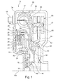
- FIG. 1 shows a cross section of a section of a torque transmission device 10 in a specific embodiment of the invention.
- Component of the torque transmission device 10 is formed as a starting clutch and rotatable about an axis of rotation 100 wet-running coupling device 12 which is enclosed by a two-part coupling housing 14, wherein a fluid is received.
- the clutch housing 14 is connectable to a driver element 16 with a drive side.
- the driver element 16 is attached to the clutch housing 14, in particular welded or riveted.
- a wall element 18 is inserted, which is rotatably connected to the clutch housing 16, in particular riveted.
- a friction device 20 is arranged, which has a clutch input part 22, consisting of a plate carrier 24 and drive side friction plates 26, wherein the plate carrier 24 is rotatably connected to the clutch housing 14, in particular riveted to the clutch housing 14.
- a pressure chamber 38 is formed by the piston member 36 relative to the support member 34 and the wall member 18 is sealed by means of a respective sealing element 40, 42.
- the pressure chamber 38 is connected to a through the wall member 18 and / or the support member 34 extending opening to a fluid line, so that an axial displacement of the piston member 36 in response to a fluid pressure in the pressure chamber 38 can be effected.
- the wall element 18 forms in a radially inner region a centering for a connectable to a transmission input shaft output hub 44, preferably, the wall member 18 for this purpose an axial portion 46, which also by means of a sealing member 48, a seal against the output hub 44 can be effected.
- the wall element 18 also has a flow-directing effect, because a fluid flowing through the friction device 20, for example for cooling the friction device 20, is forced by the design and arrangement of the wall element 18 to flow through the friction device 20 and can not substantially circumvent it, thus An efficient cooling of the friction device 20 can be effected.
- the output-side plate carrier 30 surrounds the wall element 18 and is extended radially inward and received on the output hub 44.
- a damper input part 50 of a torsional vibration damper 51 is rotatably connected, for example via a rivet 52.
- the damper input part 50 serves to act on energy storage elements 54, which can forward the Eintechnischskraft on a relative to the damper input member 50 limited rotatable damper output member 56, including the damper output member 56 is in engagement with the energy storage elements 54.
- the damper output part 56 serves to exclude and secure the energy storage elements 54 by means of a retainer 58.
- the damper output part 56 is connected to the output hub 44 by means of a riveted connection 60.
- a Tilgermassenvic 62 in particular a pendulum mass carrier 64
- a centrifugal pendulum device 66 is arranged and rotatably connected to the damper output member 56.
- the pendulum mass carrier 64 extends from the connection point radially outward and takes in a radially outer region axially on both sides pendulum masses 68, which via spacer bolts 70 are interconnected. For this purpose, the spacing bolts 70 engage through corresponding cutouts in the pendulum mass carrier 64.
- the pendulum masses 68 are limited in displacement in the pendulum mass carrier 64 rolling elements relative to the pendulum mass carrier 64 along a pendulum track. As a result, a speed-dependent eradication of torsional vibrations can be effected.
- the centrifugal pendulum device 66 is disposed axially adjacent to the torsional vibration damper 51.
- the pendulum masses 68 and the energy storage elements 54 are arranged radially overlapping with respect to the axis of rotation 100. Thereby, the torsional vibration damping can be improved because the energy storage elements 54 can be arranged on a larger effective radius.
Landscapes
- Engineering & Computer Science (AREA)
- General Engineering & Computer Science (AREA)
- Mechanical Engineering (AREA)
- Physics & Mathematics (AREA)
- Acoustics & Sound (AREA)
- Aviation & Aerospace Engineering (AREA)
- Hydraulic Clutches, Magnetic Clutches, Fluid Clutches, And Fluid Joints (AREA)
- Mechanical Operated Clutches (AREA)
Abstract
Description
- Die Erfindung betrifft eine Drehmomentübertragungseinrichtung nach dem Oberbegriff von Anspruch 1.
- Derartige Drehmomentübertragungseinrichtungen sind allgemein bekannt. So zeigt
WO2010037661 eine Drehmomentübertragungseinrichtung umfassend eine nasslaufende Kupplung mit einer Reibeinrichtung zum lösbaren Verbinden eines Kupplungseingangsteils mit einem Kupplungsausgangsteil und einen Drehschwingungsdämpfer mit einem Dämpfereingangsteil und einem gegenüber diesem entgegen der Wirkung von Energiespeicherelementen begrenzt verdrehbaren Dämpferausgangsteil, sowie eine Fliehkraftpendeleinrichtung mit einem Pendelmassenträger und beidseitig daran aufgenommenen Pendelmassen. - Dabei sind die Pendelmassen radial außerhalb der Energiespeicherelemente des Drehschwingungsdämpfers angeordnet. Dadurch kann die Dämpferkapazität nicht voll ausgeschöpft werden, da die Energiespeicherelemente auf einem verhältnismäßig zu der radialen Gesamtabmessung der Kupplung kleinen Radius wirksam sind.
- Die Aufgabe liegt darin, eine verbesserte Drehschwingungsdämpfung zu bewirken. Weiterhin kann die Aufgabe auch darin bestehen, den radialen Bauraumbedarf zu verringern.
- Die Aufgabe wird durch alle Merkmale des Gegenstands gemäß Anspruch 1 gelöst.
- Dementsprechend wird eine Drehmomentübertragungseinrichtung, umfassend eine als Anfahrkupplung ausgebildete nasslaufende Kupplungseinrichtung, aufweisend eine Drehachse, eine Reibeinrichtung zum lösbaren Verbinden eines Kupplungseingangsteils mit einem Kupplungsausgangsteil, ein Kolbenelement zur Bewirkung eines Reibeingriffs zwischen dem Kupplungseingangsteil und dem Kupplungsausgangsteil, einen Drehschwingungsdämpfer mit einem Dämpfereingangsteil und einem gegenüber diesem entgegen der Wirkung wenigstens eines Energiespeicherelements begrenzt verdrehbaren Dämpferausgangsteil und eine Tilgereinrichtung zur Tilgung von Drehschwingungen, umfassend einen Tilgermassenträger und eine daran aufgenommene Tilgermasse vorgeschlagen, wobei die Tilgermasse und das Energiespeicherelement in Bezug auf die Drehachse radial überlappend angeordnet sind. Dadurch kann eine verbesserte und effiziente Drehschwingungsdämpfung bewirkt werden. Auch kann dadurch der radiale Bauraumbedarf verringert werden.
- Zwei Bauteile sind radial überlappend zueinander angeordnet, wenn das erste Bauteil das zweite Bauteil wenigstens abschnittsweise radial überlappt und/oder ein radialer Endbereich des ersten Bauteils und einen radialer Endbereich des zweiten Bauteils radial auf gleicher Höhe angeordnet sind.
- In einer weiteren vorteilhaften speziellen Ausgestaltung der Erfindung liegt ein radial äußerster Umfang des Energiespeicherelements radial weiter aussen als oder auf gleicher Höhe wie der radial äußerste Umfang der Tilgermasse.
- In einer weiteren speziellen Ausführungsform der Erfindung ist der Tilgermassenträger mit dem Dämpfereingangsteil drehfest verbunden oder einteilig mit diesem ausgeführt. Auch kann der Tilgermassenträger mit dem Dämpferausgangsteil drehfest verbunden oder einteilig mit diesem ausgeführt sein.
- In einer speziellen Ausgestaltung der Erfindung ist das Dämpferausgangsteil drehfest mit einer Abtriebsnabe verbindbar oder über die Wirkung eines weiteren Energiespeicherelements unter Ausbildung einer weiteren Dämpferstufe gegenüber einem weiteren Dämpferausgangsteil begrenzt verdrehbar.
- In einer weiteren bevorzugten Ausgestaltung der Erfindung ist die Tilgereinrichtung als Fliehkraftpendeleinrichtung ausgebildet ist und somit der Tilgermassenträger als Pendelmassenträger und die Tilgermasse als beidseitig an dem Pendelmassenträger angeordnete und gegenüber diesem verlagerbare Pendelmassen ausgebildet ist.
- In einer weiteren speziellen Ausgestaltung der Erfindung sind die Pendelmassen mit durch den Pendelmassenträger durchgreifenden Abstandsbolzen miteinander verbunden und über in dem Pendelmassenträger aufgenommene Abrollelemente gegenüber dem Pendelmassenträger entlang einer Pendellaufbahn begrenzt verlagerbar.
- In einer weiteren vorteilhaften speziellen Ausgestaltung der Erfindung weist das Kupplungseingangsteil antriebsseitige Reiblamellen und das Kupplungsausgangsteil abtriebsseitige Reiblamellen auf und das Kolbenelement ist zur Beaufschlagung der Reiblamellen in Richtung zu dem antriebsseitigen Kupplungsgehäuse verlagerbar.
- Vorzugsweise ist benachbart zu der Reibeinrichtung ein mit dem Kupplungsgehäuse drehfest verbundenes Wandelement angeordnet und die Reiblamellen sind axial zwischen dem Wandelement und dem Kupplungsgehäuse angeordnet. Insbesondere bildet das Wandelement eine Begrenzung für einen Druckraum zur druckabhängigen Verlagerung des Kolbenelements zur Beaufschlagung der Reiblamellen.
- Weitere Vorteile und vorteilhafte Ausgestaltungen der Erfindung ergeben sich aus der Beschreibung und den Abbildungen, bei deren Darstellung zugunsten der Übersichtlichkeit auf eine maßstabsgetreue Wiedergabe verzichtet wurde. Alle erläuterten Merkmale sind nicht nur in der angegebenen Kombination, sondern auch in anderen Kombinationen beziehungsweise in Alleinstellung anwendbar, ohne den Rahmen der Erfindung zu verlassen.
- Die Erfindung wird im Folgenden unter Bezugnahme auf die Abbildungen im Speziellen beschrieben. Es zeigen im Einzelnen:
- Figur 1:
- Querschnitt eines Ausschnitts einer Drehmomentübertragungseinrichtung in einer speziellen Ausführungsform der Erfindung.
-
Figur 1 zeigt einen Querschnitt eines Ausschnitts einer Drehmomentübertragungseinrichtung 10 in einer speziellen Ausführungsform der Erfindung. Bestandteil der Drehmomentübertragungseinrichtung 10 bildet eine als Anfahrkupplung ausgebildete und um eine Drehachse 100 drehbare nasslaufende Kupplungseinrichtung 12, die von einem zweiteilig ausgebildeten Kupplungsgehäuse 14 umschlossen wird, worin ein Fluid aufgenommen ist. Das Kupplungsgehäuse 14 ist mit einem Mitnehmerelement 16 mit einer Antriebsseite verbindbar. Das Mitnehmerelement 16 ist an dem Kupplungsgehäuse 14 befestigt, insbesondere verschweißt oder vernietet. - In dem Kupplungsgehäuse 14 ist ein Wandelement 18 eingebracht, das mit dem Kupplungsgehäuse 16 drehfest verbunden ist, insbesondere vernietet ist. Zwischen diesem Wandelement 18 und dem Kupplungsgehäuse 14 ist eine Reibeinrichtung 20 angeordnet, die ein Kupplungseingangsteil 22, bestehend aus einem Lamellenträger 24 und antriebsseitigen Reiblamellen 26 aufweist, wobei der Lamellenträger 24 mit dem Kupplungsgehäuse 14 drehfest verbunden ist, insbesondere mit dem Kupplungsgehäuse 14 vernietet ist.
- Weiterhin ist ein Kupplungsausgangsteil 28 vorgesehen, das durch einen weiteren Lamellenträger 30, hier einem Aussenlamellenträger und abtriebsseitigen Reiblamellen 32 gebildet wird. Die antriebsseitigen Reiblamellen 26 und abtriebsseitigen Reiblamellen 32 können reibschlüssig miteinander verbunden werden oder voneinander gelöst werden. Dazu können vorzugsweise die antriebsseitigen Reiblamellen 26 durch ein auf einem Stützelement 34 aufgenommenes und darauf axial verlagerbares Kolbenelement 36 mit einer Kraft beaufschlagt werden.
- Auf einer den Reiblamellen 26, 32 abgewandten Seite des Kolbenelements 36 wird ein Druckraum 38 gebildet, indem das Kolbenelement 36 gegenüber dem Stützelement 34 und dem Wandelement 18 mittels jeweils einem Dichtelement 40, 42 abgedichtet ist. Der Druckraum 38 ist an eine durch das Wandelement 18 und/oder das Stützelement 34 verlaufende Öffnung an eine Fluidleitung angebunden, so dass eine axiale Verschiebung des Kolbenelements 36 in Abhängigkeit eines Fluiddrucks in dem Druckraum 38 bewirkt werden kann.
- Das Wandelement 18 bildet in einem radial innen liegenden Bereich eine Zentrierung für eine mit einer Getriebeeingangswelle verbindbaren Abtriebsnabe 44, vorzugsweise weist das Wandelement 18 hierfür einen axialen Abschnitt 46 auf, womit zudem mittels eines Dichtelements 48 eine Abdichtung gegenüber der Abtriebsnabe 44 bewirkt werden kann.
- Auch hat das Wandelement 18 eine strömungslenkende Wirkung, denn ein durch die Reibeinrichtung 20 strömendes Fluid, beispielsweise zur Kühlung der Reibeinrichtung 20, ist durch die Ausbildung und Anordnung des Wandelements 18 gezwungen, die Reibeinrichtung 20 zu durchströmen, und kann diese nicht wesentlich umgehen, womit eine effiziente Kühlung der Reibeinrichtung 20 bewirkt werden kann.
- Der abtriebsseitige Lamellenträger 30 umgreift das Wandelement 18 und ist nach radial innen verlängert und auf der Abtriebsnabe 44 aufgenommen. An dem Lamellenträger 30 ist ein Dämpfereingangsteil 50 eines Drehschwingungsdämpfers 51 drehfest angebunden, beispielsweise über eine Nietverbindung 52. Das Dämpfereingangsteil 50 dient der Beaufschlagung von Energiespeicherelementen 54, die die Einleitungskraft auf ein gegenüber dem Dämpfereingangsteil 50 begrenzt verdrehbares Dämpferausgangsteil 56 weiterleiten können, wozu auch das Dämpferausgangsteil 56 in Eingriff mit den Energiespeicherelementen 54 steht.
- Das Dämpferausgangsteil 56 dient zugleich der Ausnahme und Sicherung der Energiespeicherelemente 54 mittels eines Retainers 58. Das Dämpferausgangsteil 56 ist mit Hilfe einer Nietverbindung 60 mit der Abtriebsnabe 44 verbunden. Zwischen dem Dämpferausgangsteil 56 und der Abtriebsnabe 44 ist ein Tilgermassenträger 62, insbesondere ein Pendelmassenträger 64 einer Fliehkraftpendeleinrichtung 66 angeordnet und drehfest mit dem Dämpferausgangsteil 56 verbunden.
- Der Pendelmassenträger 64 erstreckt sich von der Anbindungsstelle nach radial aussen und nimmt in einem radial äußeren Bereich axial beidseitig Pendelmassen 68 auf, die über Abstandsbolzen 70 miteinander verbunden sind. Die Abstandsbolzen 70 greifen hierzu durch entsprechende Ausschnitte in dem Pendelmassenträger 64 durch. Die Pendelmassen 68 sind über in dem Pendelmassenträger 64 aufgenommene Abrollelemente gegenüber dem Pendelmassenträger 64 entlang einer Pendellaufbahn begrenzt verlagerbar ist. Dadurch kann eine drehzahlabhängige Tilgung von Drehschwingungen bewirkt werden.
- Die Fliehkraftpendeleinrichtung 66 ist axial benachbart zu dem Drehschwingungsdämpfer 51 angeordnet. Die Pendelmassen 68 und die Energiespeicherelemente 54 sind in Bezug auf die Drehachse 100 radial überlappend angeordnet. Dadurch kann die Drehschwingungsdämpfung verbessert werden, da die Energiespeicherelemente 54 auf einem grösseren Wirkradius angeordnet werden können.
-
- 10
- Drehmomentübertragungseinrichtung
- 12
- Kupplungseinrichtung
- 14
- Kupplungsgehäuse
- 16
- Mitnehmerelement
- 18
- Wandelement
- 20
- Reibeinrichtung
- 22
- Kupplungseingangsteil
- 24
- Lamellenträger
- 26
- Reiblamellen
- 28
- Kupplungsausgangsteil
- 30
- Lamellenträger
- 32
- Reiblamellen
- 34
- Stützelement
- 36
- Kolbenelement
- 38
- Druckraum
- 40
- Dichtelement
- 42
- Dichtelement
- 44
- Abtriebsnabe
- 46
- Abschnitt
- 48
- Dichtelement
- 50
- Dämpfereingangsteil
- 51
- Drehschwingungsdämpfer
- 52
- Nietverbindung
- 54
- Energiespeicherelement
- 56
- Dämpferausgangsteil
- 58
- Retainer
- 60
- Nietverbindung
- 62
- Tilgermassenträger
- 64
- Pendelmassenträger
- 66
- Fliehkraftpendeleinrichtung
- 68
- Pendelmassen
- 70
- Abstandsbolzen
- 100
- Drehachse
Claims (10)
- Drehmomentübertragungseinrichtung (10) umfassend eine als Anfahrkupplung ausgebildete nasslaufende Kupplungseinrichtung (12), aufweisend:eine Drehachse (100);eine Reibeinrichtung (20) zum lösbaren Verbinden eines Kupplungseingangsteils (22) mit einem Kupplungsausgangsteil (28);ein Kolbenelement (36) zur Bewirkung eines Reibeingriffs zwischen dem Kupplungseingangsteil (22) und dem Kupplungsausgangsteil (28);einen Drehschwingungsdämpfer (51) mit einem Dämpfereingangsteil (50) und einem gegenüber diesem entgegen der Wirkung wenigstens eines Energiespeicherelements (54) begrenzt verdrehbaren Dämpferausgangsteil (56);eine Tilgereinrichtung (66) zur Tilgung von Drehschwingungen, umfassend einen Tilgermassenträger (62, 64) und eine daran aufgenommene Tilgermasse (68),dadurch gekennzeichnet, dass die Tilgermasse (68) und das Energiespeicherelement (54) in Bezug auf die Drehachse (100) radial überlappend angeordnet sind.
- Drehmomentübertragungseinrichtung (10) nach Anspruch 1, wobei ein radial äußerster Umfang des Energiespeicherelements (54) radial weiter aussen liegt als oder auf gleicher Höhe liegt wie der radial äußerste Umfang der Tilgermasse (68).
- Drehmomentübertragungseinrichtung (10) nach einem der Ansprüche 1 oder 2, wobei der Tilgermassenträger (62, 64) mit dem Dämpfereingangsteil (50) drehfest verbunden oder einteilig mit diesem ausgeführt ist.
- Drehmomentübertragungseinrichtung (10) nach einem der Ansprüche 1 oder 2, wobei der Tilgermassenträger (62, 64) mit dem Dämpferausgangsteil (56) drehfest verbunden oder einteilig mit diesem ausgeführt ist.
- Drehmomentübertragungseinrichtung (10) nach einem der Ansprüche 1 bis 4, wobei das Dämpferausgangsteil (56) drehfest mit einer Abtriebsnabe (44) verbindbar ist oder über die Wirkung eines weiteren Energiespeicherelements unter Ausbildung einer weiteren Dämpferstufe gegenüber einem weiteren Dämpferausgangsteil begrenzt verdrehbar ist.
- Drehmomentübertragungseinrichtung (10) nach einem der vorangehenden Ansprüche, wobei die Tilgereinrichtung (66) als Fliehkraftpendeleinrichtung (66) ausgebildet ist und somit der Tilgermassenträger (62) als Pendelmassenträger (64) und die Tilgermasse als beidseitig an dem Pendelmassenträger (64) angeordnete und gegenüber diesem verlagerbare Pendelmassen (68) ausgebildet ist.
- Drehmomentübertragungseinrichtung (10) nach Anspruch 6, wobei die Pendelmassen (68) mit durch den Pendelmassenträger (64) durchgreifenden Abstandsbolzen (70) miteinander verbunden und über in dem Pendelmassenträger (64) aufgenommene Abrollelemente gegenüber dem Pendelmassenträger (64) entlang einer Pendellaufbahn begrenzt verlagerbar sind.
- Drehmomentübertragungseinrichtung (10) nach einem der vorangehenden Ansprüche, wobei das Kupplungseingangsteil (22) antriebsseitige Reiblamellen (26) und das Kupplungsausgangsteil (28) abtriebsseitige Reiblamellen (32) aufweist und das Kolbenelement (36) zur Beaufschlagung der Reiblamellen (26, 32) in Richtung zu dem antriebsseitigen Kupplungsgehäuse (14) verlagerbar ist.
- Drehmomentübertragungseinrichtung (10) nach Anspruch 8, wobei benachbart zu der Reibeinrichtung (20) ein mit dem Kupplungsgehäuse (14) drehfest verbundenes Wandelement (18) angeordnet ist und die Reiblamellen (26, 32) axial zwischen dem Wandelement (18) und dem Kupplungsgehäuse (14) angeordnet sind.
- Drehmomentübertragungseinrichtung (10) nach Anspruch 9, wobei das Wandelement (18) eine Begrenzung für einen Druckraum (38) zur druckabhängigen Verlagerung des Kolbenelements (36) zur Beaufschlagung der Reiblamellen (26, 32) bildet.
Applications Claiming Priority (1)
| Application Number | Priority Date | Filing Date | Title |
|---|---|---|---|
| DE102012215842 | 2012-09-06 |
Publications (3)
| Publication Number | Publication Date |
|---|---|
| EP2706263A2 true EP2706263A2 (de) | 2014-03-12 |
| EP2706263A3 EP2706263A3 (de) | 2014-09-03 |
| EP2706263B1 EP2706263B1 (de) | 2018-10-10 |
Family
ID=49003686
Family Applications (1)
| Application Number | Title | Priority Date | Filing Date |
|---|---|---|---|
| EP13181127.5A Not-in-force EP2706263B1 (de) | 2012-09-06 | 2013-08-21 | Drehmomentübertragungseinrichtung |
Country Status (2)
| Country | Link |
|---|---|
| EP (1) | EP2706263B1 (de) |
| DE (1) | DE102013216509A1 (de) |
Families Citing this family (4)
| Publication number | Priority date | Publication date | Assignee | Title |
|---|---|---|---|---|
| DE102014220897A1 (de) | 2014-10-15 | 2016-04-21 | Zf Friedrichshafen Ag | Kopplungsanordnung mit einer Schwingungsreduzierungseinrichtung und mit einer Kupplungseinrichtung |
| WO2019102098A2 (fr) * | 2017-11-22 | 2019-05-31 | Valeo Embrayages | Dispositif de transmission pour véhicule hybride |
| DE102020113182A1 (de) | 2020-05-15 | 2021-11-18 | Schaeffler Technologies AG & Co. KG | Drehmomentübertragungseinrichtung |
| DE102020120523B4 (de) * | 2020-08-04 | 2023-09-07 | Schaeffler Technologies AG & Co. KG | Trennkupplung mit einer Rotationsachse für einen Antriebsstrang |
Citations (1)
| Publication number | Priority date | Publication date | Assignee | Title |
|---|---|---|---|---|
| WO2010037661A1 (de) | 2008-09-30 | 2010-04-08 | Zf Friedrichshafen Ag | Nasslaufende anfahrkupplung |
Family Cites Families (7)
| Publication number | Priority date | Publication date | Assignee | Title |
|---|---|---|---|---|
| DE102004060256A1 (de) | 2004-12-15 | 2006-06-29 | Zf Friedrichshafen Ag | Hydrodynamische Kopplungsvorrichtung |
| DE112008003168B4 (de) | 2007-11-29 | 2022-01-05 | Schaeffler Technologies AG & Co. KG | Kraftübertragungsvorrichtung, insbesondere zur Leistungsübertragung zwischen einer Antriebsmaschine und einem Abtrieb |
| DE112009001462B4 (de) | 2008-06-16 | 2016-07-07 | Schaeffler Technologies AG & Co. KG | Doppelkupplung |
| JP5896907B2 (ja) | 2009-09-28 | 2016-03-30 | シェフラー テクノロジーズ アー・ゲー ウント コー. カー・ゲーSchaeffler Technologies AG & Co. KG | 動吸振器とねじり振動ダンパとを備えたハイドロダイナミック式のトルクコンバータ |
| JP5661789B2 (ja) | 2009-11-20 | 2015-01-28 | シェフラー テクノロジーズ アクチエンゲゼルシャフト ウント コンパニー コマンディートゲゼルシャフトSchaeffler Technologies AG & Co. KG | 二部構成の流れ分離ハブ |
| DE112011100547B4 (de) * | 2010-02-16 | 2021-01-14 | Schaeffler Technologies AG & Co. KG | Drehmomentübertragungseinrichtung |
| DE102010033552A1 (de) | 2010-08-05 | 2012-02-09 | Daimler Ag | Wandlervorrichtung |
-
2013
- 2013-08-21 DE DE102013216509.9A patent/DE102013216509A1/de not_active Ceased
- 2013-08-21 EP EP13181127.5A patent/EP2706263B1/de not_active Not-in-force
Patent Citations (1)
| Publication number | Priority date | Publication date | Assignee | Title |
|---|---|---|---|---|
| WO2010037661A1 (de) | 2008-09-30 | 2010-04-08 | Zf Friedrichshafen Ag | Nasslaufende anfahrkupplung |
Also Published As
| Publication number | Publication date |
|---|---|
| EP2706263B1 (de) | 2018-10-10 |
| EP2706263A3 (de) | 2014-09-03 |
| DE102013216509A1 (de) | 2014-03-06 |
Similar Documents
| Publication | Publication Date | Title |
|---|---|---|
| DE112011100547B4 (de) | Drehmomentübertragungseinrichtung | |
| DE112012000840B4 (de) | Drehmomentübertragungseinrichtung | |
| EP2724050B1 (de) | Drehmomentübertragungseinrichtung | |
| EP2706262A2 (de) | Drehmomentübertragungseinrichtung | |
| DE112010004737T5 (de) | Drehmomentwandler | |
| WO2011100946A1 (de) | Hydrodynamischer drehmomentwandler | |
| EP2600031A2 (de) | Drehmomentübertragungseinrichtung | |
| EP2706260B1 (de) | Drehmomentübertragungseinrichtung | |
| DE112015004982T5 (de) | Überbrückungsvorrichtung für einen Drehmomentwandler | |
| DE102014214634A1 (de) | Rotationsbaugruppe für eine Kupplung und/oder Dämpfereinrichtung sowie Drehmomentübertragungseinrichtung | |
| DE102011017658B4 (de) | Hydrodynamische Kopplungsanordnung, insbesondere hydrodynamischer Drehmomentwandler | |
| EP2706263B1 (de) | Drehmomentübertragungseinrichtung | |
| DE102014207258A1 (de) | Torsionsschwingungsdämpfer mit einer Dämpfungseinrichtung, einem Tilgersystem und einer Masseeinrichtung | |
| DE102009042838A1 (de) | Drehschwingungsdämpfer | |
| WO2016150441A1 (de) | Drehmomentübertragungseinrichtung | |
| EP2836738B1 (de) | Drehmomentübertragungseinrichtung | |
| WO2016150439A1 (de) | Drehmomentübertragungseinrichtung | |
| EP2743541A2 (de) | Drehmomentübertragungseinrichtung | |
| WO2007054047A2 (de) | Lamellenkupplung und hydrodynamische drehmomentwandler-vorrichtung mit einer solchen lamellenkupplung | |
| WO2014012543A1 (de) | Doppelkupplungseinrichtung | |
| DE102008057104B4 (de) | Kraftübertragungsvorrichtung und Verfahren zur Montage einer Dämpferanordnung in einer Kraftübertragungsvorrichtung | |
| EP2706261A2 (de) | Drehmomentübertragungseinrichtung | |
| DE102014207260A1 (de) | Torsionsschwingungsdämpfer mit einer Dämpfungseinrichtung, einem Tilgersystem und einer Masseeinrichtung | |
| EP2693077A2 (de) | Drehschwingungstilger | |
| EP3348866B1 (de) | Hydrodynamische kopplungsanordnung |
Legal Events
| Date | Code | Title | Description |
|---|---|---|---|
| PUAI | Public reference made under article 153(3) epc to a published international application that has entered the european phase |
Free format text: ORIGINAL CODE: 0009012 |
|
| AK | Designated contracting states |
Kind code of ref document: A2 Designated state(s): AL AT BE BG CH CY CZ DE DK EE ES FI FR GB GR HR HU IE IS IT LI LT LU LV MC MK MT NL NO PL PT RO RS SE SI SK SM TR |
|
| AX | Request for extension of the european patent |
Extension state: BA ME |
|
| RAP1 | Party data changed (applicant data changed or rights of an application transferred) |
Owner name: SCHAEFFLER TECHNOLOGIES GMBH & CO. KG |
|
| PUAL | Search report despatched |
Free format text: ORIGINAL CODE: 0009013 |
|
| AK | Designated contracting states |
Kind code of ref document: A3 Designated state(s): AL AT BE BG CH CY CZ DE DK EE ES FI FR GB GR HR HU IE IS IT LI LT LU LV MC MK MT NL NO PL PT RO RS SE SI SK SM TR |
|
| AX | Request for extension of the european patent |
Extension state: BA ME |
|
| RIC1 | Information provided on ipc code assigned before grant |
Ipc: F16F 15/139 20060101ALI20140729BHEP Ipc: F16F 15/14 20060101AFI20140729BHEP |
|
| RAP1 | Party data changed (applicant data changed or rights of an application transferred) |
Owner name: SCHAEFFLER TECHNOLOGIES AG & CO. KG |
|
| 17P | Request for examination filed |
Effective date: 20150303 |
|
| RBV | Designated contracting states (corrected) |
Designated state(s): AL AT BE BG CH CY CZ DE DK EE ES FI FR GB GR HR HU IE IS IT LI LT LU LV MC MK MT NL NO PL PT RO RS SE SI SK SM TR |
|
| 17Q | First examination report despatched |
Effective date: 20160912 |
|
| STAA | Information on the status of an ep patent application or granted ep patent |
Free format text: STATUS: EXAMINATION IS IN PROGRESS |
|
| GRAP | Despatch of communication of intention to grant a patent |
Free format text: ORIGINAL CODE: EPIDOSNIGR1 |
|
| STAA | Information on the status of an ep patent application or granted ep patent |
Free format text: STATUS: GRANT OF PATENT IS INTENDED |
|
| INTG | Intention to grant announced |
Effective date: 20180511 |
|
| GRAS | Grant fee paid |
Free format text: ORIGINAL CODE: EPIDOSNIGR3 |
|
| GRAA | (expected) grant |
Free format text: ORIGINAL CODE: 0009210 |
|
| STAA | Information on the status of an ep patent application or granted ep patent |
Free format text: STATUS: THE PATENT HAS BEEN GRANTED |
|
| AK | Designated contracting states |
Kind code of ref document: B1 Designated state(s): AL AT BE BG CH CY CZ DE DK EE ES FI FR GB GR HR HU IE IS IT LI LT LU LV MC MK MT NL NO PL PT RO RS SE SI SK SM TR |
|
| REG | Reference to a national code |
Ref country code: GB Ref legal event code: FG4D Free format text: NOT ENGLISH |
|
| REG | Reference to a national code |
Ref country code: CH Ref legal event code: EP Ref country code: AT Ref legal event code: REF Ref document number: 1051626 Country of ref document: AT Kind code of ref document: T Effective date: 20181015 |
|
| REG | Reference to a national code |
Ref country code: IE Ref legal event code: FG4D Free format text: LANGUAGE OF EP DOCUMENT: GERMAN |
|
| REG | Reference to a national code |
Ref country code: DE Ref legal event code: R096 Ref document number: 502013011274 Country of ref document: DE |
|
| REG | Reference to a national code |
Ref country code: NL Ref legal event code: MP Effective date: 20181010 |
|
| REG | Reference to a national code |
Ref country code: LT Ref legal event code: MG4D |
|
| PG25 | Lapsed in a contracting state [announced via postgrant information from national office to epo] |
Ref country code: NL Free format text: LAPSE BECAUSE OF FAILURE TO SUBMIT A TRANSLATION OF THE DESCRIPTION OR TO PAY THE FEE WITHIN THE PRESCRIBED TIME-LIMIT Effective date: 20181010 |
|
| PG25 | Lapsed in a contracting state [announced via postgrant information from national office to epo] |
Ref country code: ES Free format text: LAPSE BECAUSE OF FAILURE TO SUBMIT A TRANSLATION OF THE DESCRIPTION OR TO PAY THE FEE WITHIN THE PRESCRIBED TIME-LIMIT Effective date: 20181010 Ref country code: BG Free format text: LAPSE BECAUSE OF FAILURE TO SUBMIT A TRANSLATION OF THE DESCRIPTION OR TO PAY THE FEE WITHIN THE PRESCRIBED TIME-LIMIT Effective date: 20190110 Ref country code: LT Free format text: LAPSE BECAUSE OF FAILURE TO SUBMIT A TRANSLATION OF THE DESCRIPTION OR TO PAY THE FEE WITHIN THE PRESCRIBED TIME-LIMIT Effective date: 20181010 Ref country code: PL Free format text: LAPSE BECAUSE OF FAILURE TO SUBMIT A TRANSLATION OF THE DESCRIPTION OR TO PAY THE FEE WITHIN THE PRESCRIBED TIME-LIMIT Effective date: 20181010 Ref country code: HR Free format text: LAPSE BECAUSE OF FAILURE TO SUBMIT A TRANSLATION OF THE DESCRIPTION OR TO PAY THE FEE WITHIN THE PRESCRIBED TIME-LIMIT Effective date: 20181010 Ref country code: IS Free format text: LAPSE BECAUSE OF FAILURE TO SUBMIT A TRANSLATION OF THE DESCRIPTION OR TO PAY THE FEE WITHIN THE PRESCRIBED TIME-LIMIT Effective date: 20190210 Ref country code: LV Free format text: LAPSE BECAUSE OF FAILURE TO SUBMIT A TRANSLATION OF THE DESCRIPTION OR TO PAY THE FEE WITHIN THE PRESCRIBED TIME-LIMIT Effective date: 20181010 Ref country code: NO Free format text: LAPSE BECAUSE OF FAILURE TO SUBMIT A TRANSLATION OF THE DESCRIPTION OR TO PAY THE FEE WITHIN THE PRESCRIBED TIME-LIMIT Effective date: 20190110 Ref country code: FI Free format text: LAPSE BECAUSE OF FAILURE TO SUBMIT A TRANSLATION OF THE DESCRIPTION OR TO PAY THE FEE WITHIN THE PRESCRIBED TIME-LIMIT Effective date: 20181010 |
|
| PG25 | Lapsed in a contracting state [announced via postgrant information from national office to epo] |
Ref country code: AL Free format text: LAPSE BECAUSE OF FAILURE TO SUBMIT A TRANSLATION OF THE DESCRIPTION OR TO PAY THE FEE WITHIN THE PRESCRIBED TIME-LIMIT Effective date: 20181010 Ref country code: SE Free format text: LAPSE BECAUSE OF FAILURE TO SUBMIT A TRANSLATION OF THE DESCRIPTION OR TO PAY THE FEE WITHIN THE PRESCRIBED TIME-LIMIT Effective date: 20181010 Ref country code: GR Free format text: LAPSE BECAUSE OF FAILURE TO SUBMIT A TRANSLATION OF THE DESCRIPTION OR TO PAY THE FEE WITHIN THE PRESCRIBED TIME-LIMIT Effective date: 20190111 Ref country code: RS Free format text: LAPSE BECAUSE OF FAILURE TO SUBMIT A TRANSLATION OF THE DESCRIPTION OR TO PAY THE FEE WITHIN THE PRESCRIBED TIME-LIMIT Effective date: 20181010 Ref country code: PT Free format text: LAPSE BECAUSE OF FAILURE TO SUBMIT A TRANSLATION OF THE DESCRIPTION OR TO PAY THE FEE WITHIN THE PRESCRIBED TIME-LIMIT Effective date: 20190210 |
|
| REG | Reference to a national code |
Ref country code: DE Ref legal event code: R026 Ref document number: 502013011274 Country of ref document: DE |
|
| PLBI | Opposition filed |
Free format text: ORIGINAL CODE: 0009260 |
|
| PLAX | Notice of opposition and request to file observation + time limit sent |
Free format text: ORIGINAL CODE: EPIDOSNOBS2 |
|
| PG25 | Lapsed in a contracting state [announced via postgrant information from national office to epo] |
Ref country code: CZ Free format text: LAPSE BECAUSE OF FAILURE TO SUBMIT A TRANSLATION OF THE DESCRIPTION OR TO PAY THE FEE WITHIN THE PRESCRIBED TIME-LIMIT Effective date: 20181010 Ref country code: IT Free format text: LAPSE BECAUSE OF FAILURE TO SUBMIT A TRANSLATION OF THE DESCRIPTION OR TO PAY THE FEE WITHIN THE PRESCRIBED TIME-LIMIT Effective date: 20181010 Ref country code: DK Free format text: LAPSE BECAUSE OF FAILURE TO SUBMIT A TRANSLATION OF THE DESCRIPTION OR TO PAY THE FEE WITHIN THE PRESCRIBED TIME-LIMIT Effective date: 20181010 |
|
| 26 | Opposition filed |
Opponent name: VALEO EMBRAYAGES Effective date: 20190710 |
|
| PG25 | Lapsed in a contracting state [announced via postgrant information from national office to epo] |
Ref country code: SK Free format text: LAPSE BECAUSE OF FAILURE TO SUBMIT A TRANSLATION OF THE DESCRIPTION OR TO PAY THE FEE WITHIN THE PRESCRIBED TIME-LIMIT Effective date: 20181010 Ref country code: RO Free format text: LAPSE BECAUSE OF FAILURE TO SUBMIT A TRANSLATION OF THE DESCRIPTION OR TO PAY THE FEE WITHIN THE PRESCRIBED TIME-LIMIT Effective date: 20181010 Ref country code: EE Free format text: LAPSE BECAUSE OF FAILURE TO SUBMIT A TRANSLATION OF THE DESCRIPTION OR TO PAY THE FEE WITHIN THE PRESCRIBED TIME-LIMIT Effective date: 20181010 Ref country code: SM Free format text: LAPSE BECAUSE OF FAILURE TO SUBMIT A TRANSLATION OF THE DESCRIPTION OR TO PAY THE FEE WITHIN THE PRESCRIBED TIME-LIMIT Effective date: 20181010 |
|
| PG25 | Lapsed in a contracting state [announced via postgrant information from national office to epo] |
Ref country code: SI Free format text: LAPSE BECAUSE OF FAILURE TO SUBMIT A TRANSLATION OF THE DESCRIPTION OR TO PAY THE FEE WITHIN THE PRESCRIBED TIME-LIMIT Effective date: 20181010 |
|
| PLBB | Reply of patent proprietor to notice(s) of opposition received |
Free format text: ORIGINAL CODE: EPIDOSNOBS3 |
|
| PG25 | Lapsed in a contracting state [announced via postgrant information from national office to epo] |
Ref country code: TR Free format text: LAPSE BECAUSE OF FAILURE TO SUBMIT A TRANSLATION OF THE DESCRIPTION OR TO PAY THE FEE WITHIN THE PRESCRIBED TIME-LIMIT Effective date: 20181010 |
|
| GBPC | Gb: european patent ceased through non-payment of renewal fee |
Effective date: 20190821 |
|
| PG25 | Lapsed in a contracting state [announced via postgrant information from national office to epo] |
Ref country code: LU Free format text: LAPSE BECAUSE OF NON-PAYMENT OF DUE FEES Effective date: 20190821 Ref country code: MC Free format text: LAPSE BECAUSE OF FAILURE TO SUBMIT A TRANSLATION OF THE DESCRIPTION OR TO PAY THE FEE WITHIN THE PRESCRIBED TIME-LIMIT Effective date: 20181010 Ref country code: CH Free format text: LAPSE BECAUSE OF NON-PAYMENT OF DUE FEES Effective date: 20190831 Ref country code: LI Free format text: LAPSE BECAUSE OF NON-PAYMENT OF DUE FEES Effective date: 20190831 |
|
| REG | Reference to a national code |
Ref country code: BE Ref legal event code: MM Effective date: 20190831 |
|
| PG25 | Lapsed in a contracting state [announced via postgrant information from national office to epo] |
Ref country code: FR Free format text: LAPSE BECAUSE OF NON-PAYMENT OF DUE FEES Effective date: 20190831 Ref country code: IE Free format text: LAPSE BECAUSE OF NON-PAYMENT OF DUE FEES Effective date: 20190821 |
|
| PG25 | Lapsed in a contracting state [announced via postgrant information from national office to epo] |
Ref country code: BE Free format text: LAPSE BECAUSE OF NON-PAYMENT OF DUE FEES Effective date: 20190831 Ref country code: GB Free format text: LAPSE BECAUSE OF NON-PAYMENT OF DUE FEES Effective date: 20190821 |
|
| REG | Reference to a national code |
Ref country code: AT Ref legal event code: MM01 Ref document number: 1051626 Country of ref document: AT Kind code of ref document: T Effective date: 20190821 |
|
| PG25 | Lapsed in a contracting state [announced via postgrant information from national office to epo] |
Ref country code: AT Free format text: LAPSE BECAUSE OF NON-PAYMENT OF DUE FEES Effective date: 20190821 |
|
| PG25 | Lapsed in a contracting state [announced via postgrant information from national office to epo] |
Ref country code: CY Free format text: LAPSE BECAUSE OF FAILURE TO SUBMIT A TRANSLATION OF THE DESCRIPTION OR TO PAY THE FEE WITHIN THE PRESCRIBED TIME-LIMIT Effective date: 20181010 |
|
| PG25 | Lapsed in a contracting state [announced via postgrant information from national office to epo] |
Ref country code: MT Free format text: LAPSE BECAUSE OF FAILURE TO SUBMIT A TRANSLATION OF THE DESCRIPTION OR TO PAY THE FEE WITHIN THE PRESCRIBED TIME-LIMIT Effective date: 20181010 Ref country code: HU Free format text: LAPSE BECAUSE OF FAILURE TO SUBMIT A TRANSLATION OF THE DESCRIPTION OR TO PAY THE FEE WITHIN THE PRESCRIBED TIME-LIMIT; INVALID AB INITIO Effective date: 20130821 |
|
| PLAB | Opposition data, opponent's data or that of the opponent's representative modified |
Free format text: ORIGINAL CODE: 0009299OPPO |
|
| R26 | Opposition filed (corrected) |
Opponent name: VALEO EMBRAYAGES Effective date: 20190710 |
|
| PG25 | Lapsed in a contracting state [announced via postgrant information from national office to epo] |
Ref country code: MK Free format text: LAPSE BECAUSE OF FAILURE TO SUBMIT A TRANSLATION OF THE DESCRIPTION OR TO PAY THE FEE WITHIN THE PRESCRIBED TIME-LIMIT Effective date: 20181010 |
|
| PLCK | Communication despatched that opposition was rejected |
Free format text: ORIGINAL CODE: EPIDOSNREJ1 |
|
| REG | Reference to a national code |
Ref country code: DE Ref legal event code: R100 Ref document number: 502013011274 Country of ref document: DE |
|
| PLBN | Opposition rejected |
Free format text: ORIGINAL CODE: 0009273 |
|
| STAA | Information on the status of an ep patent application or granted ep patent |
Free format text: STATUS: OPPOSITION REJECTED |
|
| 27O | Opposition rejected |
Effective date: 20220724 |
|
| P01 | Opt-out of the competence of the unified patent court (upc) registered |
Effective date: 20230522 |
|
| PGFP | Annual fee paid to national office [announced via postgrant information from national office to epo] |
Ref country code: DE Payment date: 20231019 Year of fee payment: 11 |
|
| REG | Reference to a national code |
Ref country code: DE Ref legal event code: R119 Ref document number: 502013011274 Country of ref document: DE |
|
| PG25 | Lapsed in a contracting state [announced via postgrant information from national office to epo] |
Ref country code: DE Free format text: LAPSE BECAUSE OF NON-PAYMENT OF DUE FEES Effective date: 20250301 |