EP2706340A2 - Dispositif et procédé de contrôle de l'orientation d'au moins une surface optique d'un système optique - Google Patents
Dispositif et procédé de contrôle de l'orientation d'au moins une surface optique d'un système optique Download PDFInfo
- Publication number
- EP2706340A2 EP2706340A2 EP13004307.8A EP13004307A EP2706340A2 EP 2706340 A2 EP2706340 A2 EP 2706340A2 EP 13004307 A EP13004307 A EP 13004307A EP 2706340 A2 EP2706340 A2 EP 2706340A2
- Authority
- EP
- European Patent Office
- Prior art keywords
- light beam
- measurement
- measuring light
- optical
- housing
- Prior art date
- Legal status (The legal status is an assumption and is not a legal conclusion. Google has not performed a legal analysis and makes no representation as to the accuracy of the status listed.)
- Withdrawn
Links
- 230000003287 optical effect Effects 0.000 title claims abstract description 95
- 238000000034 method Methods 0.000 title abstract description 9
- 238000012360 testing method Methods 0.000 title description 7
- 238000001514 detection method Methods 0.000 claims description 67
- 238000005259 measurement Methods 0.000 claims description 67
- 238000003384 imaging method Methods 0.000 claims description 31
- 230000008878 coupling Effects 0.000 claims description 20
- 238000010168 coupling process Methods 0.000 claims description 20
- 238000005859 coupling reaction Methods 0.000 claims description 20
- 230000005540 biological transmission Effects 0.000 claims description 4
- 238000010998 test method Methods 0.000 claims description 4
- 238000006073 displacement reaction Methods 0.000 claims description 2
- 238000012544 monitoring process Methods 0.000 abstract 1
- 239000013078 crystal Substances 0.000 description 6
- 238000013461 design Methods 0.000 description 6
- 238000011161 development Methods 0.000 description 4
- 239000000428 dust Substances 0.000 description 3
- 238000004519 manufacturing process Methods 0.000 description 3
- 230000008439 repair process Effects 0.000 description 3
- 238000010276 construction Methods 0.000 description 2
- 238000011156 evaluation Methods 0.000 description 2
- 238000012423 maintenance Methods 0.000 description 2
- 230000035945 sensitivity Effects 0.000 description 2
- 230000008901 benefit Effects 0.000 description 1
- 230000008859 change Effects 0.000 description 1
- 238000005516 engineering process Methods 0.000 description 1
- 230000002349 favourable effect Effects 0.000 description 1
- 239000005337 ground glass Substances 0.000 description 1
- 238000009434 installation Methods 0.000 description 1
- 238000012986 modification Methods 0.000 description 1
- 230000004048 modification Effects 0.000 description 1
- 230000005693 optoelectronics Effects 0.000 description 1
- 230000009467 reduction Effects 0.000 description 1
- 238000002310 reflectometry Methods 0.000 description 1
- 239000004065 semiconductor Substances 0.000 description 1
- 230000003595 spectral effect Effects 0.000 description 1
- 238000001228 spectrum Methods 0.000 description 1
Images


Classifications
-
- G—PHYSICS
- G02—OPTICS
- G02B—OPTICAL ELEMENTS, SYSTEMS OR APPARATUS
- G02B27/00—Optical systems or apparatus not provided for by any of the groups G02B1/00 - G02B26/00, G02B30/00
- G02B27/30—Collimators
-
- G—PHYSICS
- G01—MEASURING; TESTING
- G01M—TESTING STATIC OR DYNAMIC BALANCE OF MACHINES OR STRUCTURES; TESTING OF STRUCTURES OR APPARATUS, NOT OTHERWISE PROVIDED FOR
- G01M11/00—Testing of optical apparatus; Testing structures by optical methods not otherwise provided for
- G01M11/02—Testing optical properties
- G01M11/0207—Details of measuring devices
-
- G—PHYSICS
- G02—OPTICS
- G02B—OPTICAL ELEMENTS, SYSTEMS OR APPARATUS
- G02B27/00—Optical systems or apparatus not provided for by any of the groups G02B1/00 - G02B26/00, G02B30/00
- G02B27/62—Optical apparatus specially adapted for adjusting optical elements during the assembly of optical systems
Definitions
- the invention relates to a device for checking the alignment of at least one optical surface of an optical system, comprising: a light source for generating a measuring light beam; a beam splitter for coupling the measuring light beam into a measuring / detection optical path which extends in a longitudinal direction of the device; an imaging optics in the measurement / detection path, by means of which the coupled measurement light beam is collimated before it exits the device to impinge on the optical surface to be tested; and a detection device for detecting the measurement light beam reflected back at the optical surface to be tested after it has traveled back along the measurement / detection path and decoupling by means of the beam splitter.
- the invention relates to a corresponding test method, comprising: generating a measuring light beam; Coupling the measurement light beam into a longitudinal measurement / detection optical path; Collimating the coupled measuring light beam and impinging the collimated measuring light beam on the optical surface to be checked or adjusted; and detecting the measurement light beam reflected back at the optical surface to be tested after it has traveled back along the measurement / detection path and decoupling from the measurement / detection path.
- autocollimator Such a device and such a method are known as “autocollimator” or “autocollimation” from the prior art.
- An important application of autocollimators is to simultaneously align multiple optical surfaces, e.g. B. lens surfaces, mirror surfaces, crystal surfaces or other interfaces in an optical system (eg., Laser system) to test or measure. On the basis of the test or measurement result can then z. B. an adjustment of the relevant optical system components are performed.
- optical surfaces can be adjusted in a plane-parallel alignment with one another and / or with respect to an optical axis.
- the basic principle of autocollimators is to combine a collimator (to generate a collimated measuring light beam) with a telescope (to detect the reflected-back measuring light beam).
- a more or less "elongated" common measurement / detection path together with common imaging optics is usually used in order to collimate the measurement light beam generated by the light source and to image the backscattered measurement light beam onto the region of the detection device.
- the light source eg laser
- the detection device eg eyepiece or imaging sensor
- the imaging optics has a deflecting mirror in order to allow the measuring light beam to emerge from the device in a direction transverse to the longitudinal direction of the device.
- the method according to the invention is accordingly characterized in that the measuring light beam is deflected in such a way that it is directed in a direction transverse to the longitudinal direction onto the optical surface to be tested.
- the device according to the invention is, to a certain extent, combined with a "periscope" in the region of the measuring light beam exit (and the entrance of the reflected measuring light beam), which advantageously makes it possible for at least the part of the device provided for the exit of the measuring light beam and / or entrance of the reflected measuring light beam to place smaller spaces between components of the optical system to be tested.
- this advantageously does not require a reduction in the length of an elongate measuring / detection path or an elongated housing region, since in practice the device can project in the direction of this "large dimension", usually without problems, transversely out of the relevant intermediate space.
- an elongate housing arrangement or an elongate (eg tubular) housing part may be provided in the device for accommodating the measurement / detection path and in particular for mounting the beam splitter and the components of the imaging optics.
- a light source As a light source z.
- a laser eg., Semiconductor laser
- z. B. an LED may be provided, preferably for generating a visible (eg red) measuring light beam.
- optical properties such as transmission and reflection coefficients of the optical device components used as well as the sensitivity of the optical detection device used should be matched to the wavelength or the wavelength spectrum of the light source used.
- the imaging optics both in the collimation of the measuring light beam and in the image of the reflected-back measuring light beam in the region of the optical detection device, it is preferable to provide an adjustability of the light source and / or the detection device, particularly preferably both in terms of Orientation and the position of the relevant component (s), in particular in order to ensure the most accurate collimation and / or imaging of the back-reflected beam in the detection device.
- the term "collimation" (of the measurement light beam) as used here, above all, encompasses the case of (in the context of the practically possible) exact parallel direction of the light beams which is preferred in almost all applications.
- the imaging optics should be interpreted differently (possibly, for example, with a further imaging optics in the path between the beam splitter and the detection device).
- the detection device comprises an eyepiece, optionally with a so-called "ocular stroke plate” (for observation or measurement of area alignments by a user), wherein depending on the type of light source used, an indirect detection of the back-reflected measuring light beam is preferred, in which of or the spots reflected back on a viewing screen ("ground glass”) are observed over the eyepiece.
- a so-called "ocular stroke plate” for observation or measurement of area alignments by a user
- the detection device preferably comprises a spatially resolving (eg, imaging) optical or optoelectronic sensor system for the (at least one) back-reflected measuring light beam.
- a spatially resolving (eg, imaging) optical or optoelectronic sensor system for the (at least one) back-reflected measuring light beam.
- z. B. a suitable sensor (eg, CCD, CMOS image sensor, etc.) are arranged in an imaging plane of the detection device.
- a screen for generating a light spot per reflected beam may be arranged in the imaging plane, whereby an image of this screen is recorded by means of a camera (eg CCD camera).
- the camera can do this z. B. on the back of the screen to record the screen (light spot (s)) from the back and output, for example, to a connectable to the device monitor (for playback for a user).
- the deflecting mirror of the imaging optics is arranged such that the measuring light beam emerges at least approximately orthogonally to the longitudinal direction of the device (deflection angle of 90 °).
- the angle between the longitudinal direction and exit direction z. B. in the range of 80 ° to 100 °. This usually results in a particularly advantageous applicability of the device even in the smallest intervals of the relevant optical system.
- the device comprises a housing or housing part with an exit opening at which the collimated measurement light beam exits the device (and the back-reflected measurement light beam enters the device).
- the outlet opening here is preferably at most slightly larger than the beam cross section of the exiting jet.
- the housing is provided in the region of the outlet opening with means for fastening and / or adjustment or adjustment of a "system adapter".
- a "system adapter” preferably replaceable provided investment adapter
- the z. B. may be formed as a patch on the outside of the outlet opening adapter ring, z. B. be useful to ensure a desired relative position of the device on or in the optical system by a direct investment of the distal adapter side to a component of the optical system to be tested or to be adjusted. This makes the handling of the device particularly comfortable for a user).
- the provided on the device attachment and / or adjustment means for such a system adapter can, for. B.
- the plant adapter in turn is equipped with fastening means for fixing the device to a stationary part or a component of the system to be tested.
- said housing or housing part in the region of the outlet opening has a housing dimension of less than 4 cm, in particular less than 3 cm, viewed in the exit direction (jet direction).
- a small size advantageously allows the use of the device in correspondingly small spaces of the respective optical system.
- a lens of the imaging optics is arranged on (including "in") of the outlet opening.
- the imaging optics comprise a (single) focusing lens which serves as a "collimating lens” for the measurement light beam and at the same time as an imaging lens for the back-reflected measurement light beam.
- the above-mentioned lens arranged in the region of the beam exit (outlet opening) may in particular be such a focusing lens or collimating lens.
- a lens arranged at the outlet opening is an example of an optical element of the imaging optical system, which is arranged behind the deflection mirror in the beam path of the measuring light beam.
- elements of the imaging optics can be arranged both in front of and behind the deflection mirror.
- the mentioned arrangement of a focusing lens of the imaging optics behind the deflection mirror is z. B. advantageous to accommodate the longest possible optical measurement / detection path in the device housing.
- a lens can advantageously act simultaneously as the outlet opening occlusive dust cover.
- a window transparent to the measuring light may also be provided.
- a so-called “geometric beam splitting” may be provided, in which the coupling or decoupling takes place by means of a mirror which is inclined and slightly laterally offset with respect to an optical axis of the measuring / detection path, so that the measuring light beam and the back-reflected measuring light beam In the area of the beam splitter, so to speak, they pass one another, with one of the measuring light beam and the reflected measuring light beam being coupled in or coupled out by means of the deflecting mirror.
- the deflection mirror can, for. B. Be arranged inclined at 45 ° with respect to the optical axis, so that there is a beam deflection (for the coupling or for the coupling) by 90 °.
- the beam splitter can provide a so-called "physical beam splitting" in which the coupling or decoupling is realized by means of a partially transmitting mirror arranged on the optical axis of the measuring / detection path and inclined with respect to this optical axis.
- a partially transmitting mirror arranged on the optical axis of the measuring / detection path and inclined with respect to this optical axis.
- one of the measurement light beam and the reflected measurement light beam is reflected by the mirror (eg with a deflection angle of at least approximately 90 °, with an inclination angle of approximately 45 °), whereas the other beam passes through the partially transmissive mirror without being deflected.
- the partially transmissive mirror is formed by a beam splitter cube (of two joined prisms).
- the coupling or decoupling of the measuring light beam or of the reflected measuring light beam at the beam splitter is provided as a transmission through the beam splitter, ie without beam deflection, whereas in the decoupling or coupling a multiple, in particular double, beam deflection is provided such that the beam in question is deflected by at least approximately 180 ° (for example by two 90 ° deflections) or that the beam in question undergoes a parallel displacement without appreciable deflection (eg by two 90 ° deflections with opposite deflection orientations).
- a lateral housing bulge can be avoided in that, instead of the conventional 90 ° angular offset between the coupling-in direction and the coupling-out direction, a lateral Positional offset of the light source and detection device is provided, but at least approximately a parallelism of the directions of the input and out coupling measuring light beams is provided.
- the optical axis of the measurement / detection path, the optical axis of the light source and the optical axis of the detection device may all be provided in parallel with each other.
- the light source and the detection device are not arranged on the same side (viewed in the longitudinal direction) of the beam splitter. Rather, for reasons of space, it is generally more favorable to arrange only one side of the beam splitter facing away from the measurement / detection path, whereas the other of these two device components is arranged "in front of the beam splitter" (viewed in the longitudinal direction in the area of the measurement / detection path) but with a lateral offset to the optical axis of the measurement / detection path.
- a structurally simple realization of the above embodiment with parallel optical axes of the measuring / detection path, the light source and the detection device provides for the use of a combination of two mirrors or mirror surfaces, one of these mirrors being a partially transmissive mirror according to the above-mentioned principle of "physical Beam splitting "is used, whereas the other mirror acts as a deflection mirror, which either deflects the measuring light beam generated by the light source before it hits the partially transmissive mirror, or redirects the partially reflecting mirror coupled out by reflection reflected back measurement light beam into the optical axis of the detection device.
- the two said mirror, z. B. an angle of at least approximately 90 °, z. B. separately formed or z. B. be formed by appropriately coated surfaces of a prism. Also, this z. B. a beam splitter cube with another separately formed mirror can be used.
- a particularly interesting use of the device or the method according to the invention results z. B. for the adjustment of optical components of a laser system.
- the use of the invention hereby can be used both in a design of a laser system or laser resonator and in the case of maintenance or repair (if, for example, a component of the relevant system has been replaced).
- the invention is by no means limited to this field of application but may be used in various technical fields, in particular to adjust optical surfaces plane-parallel or to check (including "measure") angular deviations of respective optical surfaces from each other and / or with respect to an optical axis of the system. ).
- peripheral beam deflection greatly simplifies a test or adjustment of optical surfaces even in areas difficult to access due to limited space.
- the invention not only a placement of the device on laser resonator outputs, ie outside of the actual laser system can be made, but it can also be components within the system in question (eg., Laser resonator) by appropriate interposition of the device arbitrarily compared to each other.
- the user can comfortably and quickly adjust a laser resonator with an autocollimator according to the invention, both in the production and in the case of repair in the field.
- Fig. 1 shows an autocollimator 10 for checking the angular orientation of at least one optical surface of a (in Fig. 1 not shown) optical system.
- the autocollimator 10 has as a light source for generating a measuring light beam, a laser 12 which emits in the visible spectral range, for. B. a suitable laser diode.
- This laser 12 is housed in a housing portion 14-1 of a total of 14 designated Autokollimatorgereheats.
- Fig. 1 represented by the laser 12 with a certain angular divergence generated measuring light beam is deflected by means of a beam splitter cube 16 or contained therein partially transparent mirror surface 17 by 90 ° and thus coupled into an optical "measurement / detection path" 18, which in a hereinafter also referred to as the longitudinal direction L.
- Direction in a further tube-like housing portion 14-2 of the housing 14 extends.
- the measurement / detection path 18 of the autocollimator 10 includes imaging optics, which in the illustrated example is formed by a collimating lens 20 and a deflection mirror 22.
- imaging optics 20, 22 the measurement light beam coupled into the measurement / detection path 18 is collimated and deflected at the end of the housing region 14-2, so that the measurement light beam exits the collimator 10 orthogonal to the longitudinal direction L, to (in use situation) one or more apply to be tested optical surfaces.
- z. B. is a flat surface, and the (exactly) collimated measuring light beam orthogonally incident on this surface, the measuring light beam to a greater or lesser extent (depending on the reflectivity the surface) back to itself (autocollimation).
- a different orientation of the surface leads to an angular deviation between the incident measuring light beam and the back-reflected measuring light beam. Accordingly, the orientation of the relevant optical surface (s) can be checked or, if necessary, measured quantitatively by detecting the back-reflected measuring light beam.
- the illustrated autocollimator further comprises a detection device for detecting the back-reflected measuring light beam after it has traveled back along the measuring / detection path 18 and decoupling by means of the beam splitter 16.
- the detection device is formed in the example shown from an observation screen 24 and a camera 26.
- Each reflected-back measuring light beam generates on the "dome-like" screen 24 a light spot whose position is characteristic of the angular orientation of the reflecting surface. A user can change this position (s) z. B. on an external monitor connected to the camera 26 (in Fig. 1 not shown).
- the measurement / detection path 18 serves both for imaging or beamforming (collimation) of the measurement light beam emitted by the autocollimator 10 and, in the reverse direction, for imaging or beamforming the measurement light beam to be detected back.
- the decoupling of the back-reflected measurement light beam from the measurement / acquisition path 18 is based in the illustrated example on the partial transmission of the beam splitter mirror 17 formed in the beam splitter cube 16.
- the beam splitter or the beam splitter cube 16 used for this purpose makes it possible to use the measuring / detection path 18 for both the emitted and the reflected measuring light beam, without mutual spatial interference between light source (here: laser 12) and detection device (here: observation screen 24 and camera 26 ).
- the detection device 24, 26 is to be arranged in a housing portion 14-3, which is like the housing portion 14-2 in the longitudinal direction L, but extends on the "other side" of the beam splitter 16 viewed in the longitudinal direction L.
- a decisive advantage of the autocollimator 10 is that it can be used, in particular, in confined spatial conditions, since a housing dimension a relevant for this purpose, namely the housing dimension considered in the region of an outlet opening 30 for the exiting measuring light beam, is comparatively small.
- the housing dimension a corresponds to a diameter or a width at the distal end of the housing portion 14-2. The considerable length of this housing portion 14-2 does not matter for this purpose.
- the housing dimension a can, for. B. by at least a factor of 5, in particular by at least a factor of 10 smaller than the dimension considered in the longitudinal direction L of the housing 14 be.
- the dimension a is preferably less than 4 cm, more preferably less than 3 cm.
- FIG. 2 Figure 11 illustrates a usage situation in which the autocollimator 10 is used in confined spaces within a laser system 50 for adjusting its system components 50-1 through 50-4.
- the laser system 50 includes a first resonator mirror (eg, partially transmissive output mirror) 50-1, a laser crystal ("active medium") 50-2, a Q-switch 50-3, and a second (FIG. eg fully reflecting) Resonatorpiege! 50-4.
- a first resonator mirror eg, partially transmissive output mirror
- active medium e.g., laser crystal
- Q-switch e.g. fully reflecting
- the laser system 50 During the adjustment of the laser system 50, either during its production or after replacement of at least one of the components 50-1 to 50-4 in the context of a maintenance or a repair, it is about the components 50-1 to 50 by means of the autocollimator 10 -4 or their relevant, ie optically effective surfaces 52 to 62 in a desired manner with respect to an optical axis 70 of the laser system to align.
- the relatively small housing dimension a in the case of the autocollimator 10 makes it possible to advantageously place the end of the housing area 14-2 having the outlet opening 30 in each of the intermediate spaces between the components 50-1 to 50-4.
- the clear widths of these spaces are in Fig. 2 designated A1, A2 and A3.
- the housing dimension a is advantageously smaller than each of the gap widths A1 to A3.
- the assignment of the observable on the screen 24 light spots to the individual surfaces 54 to 62 may, for. B. by probeweizes adjustment of the relevant components 50-2 to 50-4 (and / or by taking into account the light spot intensities) are determined.
- the aim of the adjustment is to coincide all the light spots on the screen 24 (in the center of the screen), which the user can accomplish in a comfortable manner by means of corresponding adjustment operations on the components 50-2 to 50-4 while observing the light spots.
- the procedure described above makes it possible to achieve a desired adjustment of the components 50-2 to 50-4 with respect to a common optical axis, here the optical axis 70.
- the autocollimator 10 z. B placed in the space between the laser crystal 50-2 and the Q-switch 50-3, so that the reflections from the surfaces 52, 54 and 56 resulting light spots are detected. If, in this situation, the autocollimator 10 is initially aligned such that the light spots resulting from the surfaces 54 and 56 of the laser crystal 50-2 migrate into the center of the screen, its associated light spot can then also be brought into the screen center by corresponding adjustment of the mirror 50-1 Consequently, the mirror 50-1 is thus also aligned with the common optical axis 70.
- the autocollimator 10 can thus also be used on any other optical systems and in other ways or for other purposes. It represents a universal adjustment, measuring and test equipment not only in laser technology.
- the special use of the autocollimator 10 or a calibration method performed therefor, as exemplarily described above, for laser systems is of particular interest insofar as laser systems become increasingly compact and smaller so that conventional autocollimators are difficult or impossible (eg with a placement outside the laser resonator) can be used.
- the autocollimator 10 retains the basic operating principle of conventional autocollimators. Due to the modification of the imaging optics according to the invention with the "periscope-type" deflecting mirror 22, the autocollimator 10, however, is considerably improved for use in confined spatial conditions, in particular for the laser adjustment.
- the use or installation of the camera 26 is optional.
- the observation could alternatively also z. B. with the naked eye or by means of an eyepiece.
- the autocollimator 10 its housing 14 is provided in the region of the outlet opening 30 (and / or on the opposite housing side) with means (eg internal or external thread, plug-in recess (s) or pin (s) or the like). provided to attach a "system adapter" on the housing 14 (and adjust if necessary) can.
- a "system adapter” on the housing 14 can be attached to attach a "system adapter" on the housing 14 (and adjust if necessary) can.
- the abutment adapter 31 can be a useful tool to ensure a desired position of the autocollimator 10 with respect to the system by a well defined abutment of the distal adapter side on a stationary component of the optical system to be tested or adjusted to simplify.
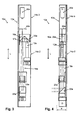
- the 3 and 4 show a further embodiment of an autocollimator 10a with a modified housing concept.
- a housing part namely a mounting profile (here eg an L-profile) 13a, which is used for mounting or storage of Autokollimatorkomponenten and after its manufacture (assembly with the required Components) with at least one further (not shown) housing part is combined.
- a mounting profile here eg an L-profile
- it may be z. B. also act to an elongated profile part, z. B. serving as a housing shell hollow square profile, in which the assembled mounting profile 13 a is inserted and secured therein.
- a housing region projecting transversely from the longitudinal direction is advantageously omitted for accommodating the light source 12a.
- the autocollimator 10a also has a housing region 14a-2 elongated in the longitudinal direction L and the housing region 14a-3 extending beyond it and also extending in the longitudinal direction L "beyond a beam splitter 16a". A with respect to the compactness of the housing structure rather disadvantageous transverse projecting housing part is eliminated.
- FIGS. 5 and 6 show a further embodiment of an autocollimator 10b, whose construction or housing concept substantially the embodiment according to the 3 and 4 equivalent.
- a collimating lens 20b is not arranged in front of, but behind, a deflecting mirror 22b provided for the "periscope-like" beam deflection in the course of the measuring light beam.
- this lens 20b can thus advantageously be arranged in the region of that housing opening at which the measuring light beam exits, in order to simultaneously act as dust protection at this point.
Landscapes
- Physics & Mathematics (AREA)
- General Physics & Mathematics (AREA)
- Optics & Photonics (AREA)
- Chemical & Material Sciences (AREA)
- Analytical Chemistry (AREA)
- Length Measuring Devices By Optical Means (AREA)
- Investigating Materials By The Use Of Optical Means Adapted For Particular Applications (AREA)
Applications Claiming Priority (1)
| Application Number | Priority Date | Filing Date | Title |
|---|---|---|---|
| DE201210017519 DE102012017519A1 (de) | 2012-09-05 | 2012-09-05 | Vorrichtung und Verfahren zum Prüfen der Ausrichtung wenigstens einer optischen Fläche eines optischen Systems |
Publications (2)
| Publication Number | Publication Date |
|---|---|
| EP2706340A2 true EP2706340A2 (fr) | 2014-03-12 |
| EP2706340A3 EP2706340A3 (fr) | 2015-03-04 |
Family
ID=49110966
Family Applications (1)
| Application Number | Title | Priority Date | Filing Date |
|---|---|---|---|
| EP20130004307 Withdrawn EP2706340A3 (fr) | 2012-09-05 | 2013-09-02 | Dispositif et procédé de contrôle de l'orientation d'au moins une surface optique d'un système optique |
Country Status (2)
| Country | Link |
|---|---|
| EP (1) | EP2706340A3 (fr) |
| DE (1) | DE102012017519A1 (fr) |
Cited By (6)
| Publication number | Priority date | Publication date | Assignee | Title |
|---|---|---|---|---|
| CN113218338A (zh) * | 2021-05-18 | 2021-08-06 | 安徽中科米微电子技术有限公司 | 一种基于自准直仪的多点位测试装置及测试方法 |
| CN113916510A (zh) * | 2021-11-23 | 2022-01-11 | 江苏北方湖光光电有限公司 | 基于伺服转动下的多光轴图像偏差校准方法 |
| CN114545645A (zh) * | 2022-02-28 | 2022-05-27 | 北京半导体专用设备研究所(中国电子科技集团公司第四十五研究所) | 一种潜望式集成光路的装调方法 |
| CN115165290A (zh) * | 2022-06-20 | 2022-10-11 | 中国航天空气动力技术研究院 | 一种风洞攻角机构标校装置及方法 |
| CN115291406A (zh) * | 2022-07-20 | 2022-11-04 | 中国航空工业集团公司济南特种结构研究所 | 一种基于激光准直的光轴校准装置 |
| CN120028015A (zh) * | 2025-04-23 | 2025-05-23 | 长春通视光电技术股份有限公司 | 一种用于反射镜振动力热耦合的原位测量装置及使用方法 |
Family Cites Families (2)
| Publication number | Priority date | Publication date | Assignee | Title |
|---|---|---|---|---|
| DE3034922C2 (de) * | 1980-09-16 | 1982-11-25 | Siemens AG, 1000 Berlin und 8000 München | Justier- und Prüfeinrichtung für ein Laserentfernungsmeßsystem |
| DE3619931C1 (en) * | 1986-06-13 | 1987-10-29 | Daimler Benz Ag | Device for optical alignment measurement between two variously rotatable shafts |
-
2012
- 2012-09-05 DE DE201210017519 patent/DE102012017519A1/de not_active Ceased
-
2013
- 2013-09-02 EP EP20130004307 patent/EP2706340A3/fr not_active Withdrawn
Non-Patent Citations (1)
| Title |
|---|
| None |
Cited By (9)
| Publication number | Priority date | Publication date | Assignee | Title |
|---|---|---|---|---|
| CN113218338A (zh) * | 2021-05-18 | 2021-08-06 | 安徽中科米微电子技术有限公司 | 一种基于自准直仪的多点位测试装置及测试方法 |
| CN113916510A (zh) * | 2021-11-23 | 2022-01-11 | 江苏北方湖光光电有限公司 | 基于伺服转动下的多光轴图像偏差校准方法 |
| CN113916510B (zh) * | 2021-11-23 | 2023-09-26 | 江苏北方湖光光电有限公司 | 基于伺服转动下的多光轴图像偏差校准方法 |
| CN114545645A (zh) * | 2022-02-28 | 2022-05-27 | 北京半导体专用设备研究所(中国电子科技集团公司第四十五研究所) | 一种潜望式集成光路的装调方法 |
| CN114545645B (zh) * | 2022-02-28 | 2023-09-26 | 北京半导体专用设备研究所(中国电子科技集团公司第四十五研究所) | 一种潜望式集成光路的装调方法 |
| CN115165290A (zh) * | 2022-06-20 | 2022-10-11 | 中国航天空气动力技术研究院 | 一种风洞攻角机构标校装置及方法 |
| CN115165290B (zh) * | 2022-06-20 | 2024-06-11 | 中国航天空气动力技术研究院 | 一种风洞攻角机构标校装置及方法 |
| CN115291406A (zh) * | 2022-07-20 | 2022-11-04 | 中国航空工业集团公司济南特种结构研究所 | 一种基于激光准直的光轴校准装置 |
| CN120028015A (zh) * | 2025-04-23 | 2025-05-23 | 长春通视光电技术股份有限公司 | 一种用于反射镜振动力热耦合的原位测量装置及使用方法 |
Also Published As
| Publication number | Publication date |
|---|---|
| DE102012017519A1 (de) | 2014-03-06 |
| EP2706340A3 (fr) | 2015-03-04 |
Similar Documents
| Publication | Publication Date | Title |
|---|---|---|
| EP3140609B1 (fr) | Dispositif de mesure de la profondeur d'un cordon de soudure en temps réel | |
| EP2256516B1 (fr) | Appareil laser pour la mesure électro-optique de distances | |
| EP0801760B1 (fr) | Procede et dispositif permettant de determiner la distance entre un detail d'un objet et un microscope chirurgical | |
| EP3990887A1 (fr) | Ensemble capteur destiné à la caractérisation de particules | |
| EP2706340A2 (fr) | Dispositif et procédé de contrôle de l'orientation d'au moins une surface optique d'un système optique | |
| EP3221742B1 (fr) | Séparateur de faisceau et dispositif d'examen d'un échantillon excitable au moyen d'un rayonnement électromagnétique | |
| DE102013113265B4 (de) | Vorrichtung zur berührungslosen optischen Abstandsmessung | |
| EP2836818A1 (fr) | Système de détection de gaz | |
| DE102009027797A1 (de) | Optische Einrichtung und Verfahren zu deren Überprüfung | |
| DE2714412C3 (de) | Elektrooptisches Rückstrahl-Ortungsgerät, insbesondere Laserentfernungsmesser mit in einen Visierzweig eingekoppelter Zielmarke | |
| DE102007030880B4 (de) | Vorrichtung zur Erfassung einer Objektszene | |
| DE102017200691A1 (de) | Projektionsvorrichtung und Verfahren zum Abtasten eines Raumwinkelbereichs mit einem Laserstrahl | |
| WO2018011350A1 (fr) | Système optique de compensation de défauts d'alignement d'un réflecteur par rapport à une source de lumière | |
| DE102012106779B4 (de) | Optik für Strahlvermessung | |
| DE202009007612U1 (de) | Reflexionslichtschrankensensor | |
| EP4225530B1 (fr) | Unité de fibre optique, système laser comprenant une telle unité de fibre optique, et procédé pour évaluer la qualité d'injection lors de l'injection de lumière utile dans une unité de fibre optique de ce type | |
| DE10031414B4 (de) | Vorrichtung zur Vereinigung optischer Strahlung | |
| DE10301607B4 (de) | Interferenzmesssonde | |
| EP2690398B1 (fr) | Dispositif de détermination de la position d'éléments mécaniques | |
| DE10320991B4 (de) | Optische Positionsmesseinrichtung | |
| DE102008011761A1 (de) | Justagevorrichtung für eine Mikrolithografie-Projektionsbelichtungsanlage, Beleuchtungssystem mit einer derartigen Justagevorrichtung sowie Projektionsbelichtungsanlage mit einem derartigen Beleuchtungssystem | |
| DE102022110651A1 (de) | Kompaktes optisches Spektrometer | |
| DE102018113136B4 (de) | Kameramodul und Kamerasystem mit einem Kameramodul | |
| WO2021224254A1 (fr) | Dispositif d'essai pour capteur optique actif | |
| DE10126480A1 (de) | Verfahren zur Messung der Winkellage und der Defokussierung eines optischen Referenzelements |
Legal Events
| Date | Code | Title | Description |
|---|---|---|---|
| PUAI | Public reference made under article 153(3) epc to a published international application that has entered the european phase |
Free format text: ORIGINAL CODE: 0009012 |
|
| AK | Designated contracting states |
Kind code of ref document: A2 Designated state(s): AL AT BE BG CH CY CZ DE DK EE ES FI FR GB GR HR HU IE IS IT LI LT LU LV MC MK MT NL NO PL PT RO RS SE SI SK SM TR |
|
| AX | Request for extension of the european patent |
Extension state: BA ME |
|
| PUAL | Search report despatched |
Free format text: ORIGINAL CODE: 0009013 |
|
| AK | Designated contracting states |
Kind code of ref document: A3 Designated state(s): AL AT BE BG CH CY CZ DE DK EE ES FI FR GB GR HR HU IE IS IT LI LT LU LV MC MK MT NL NO PL PT RO RS SE SI SK SM TR |
|
| AX | Request for extension of the european patent |
Extension state: BA ME |
|
| RIC1 | Information provided on ipc code assigned before grant |
Ipc: G01M 11/02 20060101ALI20150127BHEP Ipc: G01M 11/00 20060101AFI20150127BHEP Ipc: G02B 27/30 20060101ALI20150127BHEP Ipc: G02B 27/62 20060101ALI20150127BHEP |
|
| STAA | Information on the status of an ep patent application or granted ep patent |
Free format text: STATUS: THE APPLICATION IS DEEMED TO BE WITHDRAWN |
|
| 18D | Application deemed to be withdrawn |
Effective date: 20150905 |