EP2706452A2 - Appareil et procédé de gestion d'usure pour système de stockage - Google Patents
Appareil et procédé de gestion d'usure pour système de stockage Download PDFInfo
- Publication number
- EP2706452A2 EP2706452A2 EP13182808.9A EP13182808A EP2706452A2 EP 2706452 A2 EP2706452 A2 EP 2706452A2 EP 13182808 A EP13182808 A EP 13182808A EP 2706452 A2 EP2706452 A2 EP 2706452A2
- Authority
- EP
- European Patent Office
- Prior art keywords
- wear
- storage nodes
- storage
- wear management
- data
- Prior art date
- Legal status (The legal status is an assumption and is not a legal conclusion. Google has not performed a legal analysis and makes no representation as to the accuracy of the status listed.)
- Withdrawn
Links
Images


Classifications
-
- G—PHYSICS
- G06—COMPUTING OR CALCULATING; COUNTING
- G06F—ELECTRIC DIGITAL DATA PROCESSING
- G06F11/00—Error detection; Error correction; Monitoring
- G06F11/30—Monitoring
-
- G—PHYSICS
- G06—COMPUTING OR CALCULATING; COUNTING
- G06F—ELECTRIC DIGITAL DATA PROCESSING
- G06F3/00—Input arrangements for transferring data to be processed into a form capable of being handled by the computer; Output arrangements for transferring data from processing unit to output unit, e.g. interface arrangements
- G06F3/06—Digital input from, or digital output to, record carriers, e.g. RAID, emulated record carriers or networked record carriers
- G06F3/0601—Interfaces specially adapted for storage systems
- G06F3/0602—Interfaces specially adapted for storage systems specifically adapted to achieve a particular effect
- G06F3/0604—Improving or facilitating administration, e.g. storage management
-
- G—PHYSICS
- G06—COMPUTING OR CALCULATING; COUNTING
- G06F—ELECTRIC DIGITAL DATA PROCESSING
- G06F12/00—Accessing, addressing or allocating within memory systems or architectures
-
- G—PHYSICS
- G06—COMPUTING OR CALCULATING; COUNTING
- G06F—ELECTRIC DIGITAL DATA PROCESSING
- G06F12/00—Accessing, addressing or allocating within memory systems or architectures
- G06F12/02—Addressing or allocation; Relocation
- G06F12/0223—User address space allocation, e.g. contiguous or non contiguous base addressing
- G06F12/023—Free address space management
- G06F12/0238—Memory management in non-volatile memory, e.g. resistive RAM or ferroelectric memory
- G06F12/0246—Memory management in non-volatile memory, e.g. resistive RAM or ferroelectric memory in block erasable memory, e.g. flash memory
-
- G—PHYSICS
- G06—COMPUTING OR CALCULATING; COUNTING
- G06F—ELECTRIC DIGITAL DATA PROCESSING
- G06F3/00—Input arrangements for transferring data to be processed into a form capable of being handled by the computer; Output arrangements for transferring data from processing unit to output unit, e.g. interface arrangements
- G06F3/06—Digital input from, or digital output to, record carriers, e.g. RAID, emulated record carriers or networked record carriers
- G06F3/0601—Interfaces specially adapted for storage systems
- G06F3/0602—Interfaces specially adapted for storage systems specifically adapted to achieve a particular effect
- G06F3/0614—Improving the reliability of storage systems
- G06F3/0616—Improving the reliability of storage systems in relation to life time, e.g. increasing Mean Time Between Failures [MTBF]
-
- G—PHYSICS
- G06—COMPUTING OR CALCULATING; COUNTING
- G06F—ELECTRIC DIGITAL DATA PROCESSING
- G06F3/00—Input arrangements for transferring data to be processed into a form capable of being handled by the computer; Output arrangements for transferring data from processing unit to output unit, e.g. interface arrangements
- G06F3/06—Digital input from, or digital output to, record carriers, e.g. RAID, emulated record carriers or networked record carriers
- G06F3/0601—Interfaces specially adapted for storage systems
- G06F3/0628—Interfaces specially adapted for storage systems making use of a particular technique
- G06F3/0638—Organizing or formatting or addressing of data
- G06F3/064—Management of blocks
-
- G—PHYSICS
- G06—COMPUTING OR CALCULATING; COUNTING
- G06F—ELECTRIC DIGITAL DATA PROCESSING
- G06F3/00—Input arrangements for transferring data to be processed into a form capable of being handled by the computer; Output arrangements for transferring data from processing unit to output unit, e.g. interface arrangements
- G06F3/06—Digital input from, or digital output to, record carriers, e.g. RAID, emulated record carriers or networked record carriers
- G06F3/0601—Interfaces specially adapted for storage systems
- G06F3/0628—Interfaces specially adapted for storage systems making use of a particular technique
- G06F3/0646—Horizontal data movement in storage systems, i.e. moving data in between storage devices or systems
- G06F3/0652—Erasing, e.g. deleting, data cleaning, moving of data to a wastebasket
-
- G—PHYSICS
- G06—COMPUTING OR CALCULATING; COUNTING
- G06F—ELECTRIC DIGITAL DATA PROCESSING
- G06F3/00—Input arrangements for transferring data to be processed into a form capable of being handled by the computer; Output arrangements for transferring data from processing unit to output unit, e.g. interface arrangements
- G06F3/06—Digital input from, or digital output to, record carriers, e.g. RAID, emulated record carriers or networked record carriers
- G06F3/0601—Interfaces specially adapted for storage systems
- G06F3/0628—Interfaces specially adapted for storage systems making use of a particular technique
- G06F3/0653—Monitoring storage devices or systems
-
- G—PHYSICS
- G06—COMPUTING OR CALCULATING; COUNTING
- G06F—ELECTRIC DIGITAL DATA PROCESSING
- G06F3/00—Input arrangements for transferring data to be processed into a form capable of being handled by the computer; Output arrangements for transferring data from processing unit to output unit, e.g. interface arrangements
- G06F3/06—Digital input from, or digital output to, record carriers, e.g. RAID, emulated record carriers or networked record carriers
- G06F3/0601—Interfaces specially adapted for storage systems
- G06F3/0668—Interfaces specially adapted for storage systems adopting a particular infrastructure
- G06F3/0671—In-line storage system
- G06F3/0673—Single storage device
- G06F3/0679—Non-volatile semiconductor memory device, e.g. flash memory, one time programmable memory [OTP]
-
- G—PHYSICS
- G06—COMPUTING OR CALCULATING; COUNTING
- G06F—ELECTRIC DIGITAL DATA PROCESSING
- G06F3/00—Input arrangements for transferring data to be processed into a form capable of being handled by the computer; Output arrangements for transferring data from processing unit to output unit, e.g. interface arrangements
- G06F3/06—Digital input from, or digital output to, record carriers, e.g. RAID, emulated record carriers or networked record carriers
- G06F3/0601—Interfaces specially adapted for storage systems
- G06F3/0668—Interfaces specially adapted for storage systems adopting a particular infrastructure
- G06F3/0671—In-line storage system
- G06F3/0683—Plurality of storage devices
- G06F3/0688—Non-volatile semiconductor memory arrays
-
- G—PHYSICS
- G06—COMPUTING OR CALCULATING; COUNTING
- G06F—ELECTRIC DIGITAL DATA PROCESSING
- G06F2212/00—Indexing scheme relating to accessing, addressing or allocation within memory systems or architectures
- G06F2212/72—Details relating to flash memory management
- G06F2212/7204—Capacity control, e.g. partitioning, end-of-life degradation
-
- G—PHYSICS
- G06—COMPUTING OR CALCULATING; COUNTING
- G06F—ELECTRIC DIGITAL DATA PROCESSING
- G06F2212/00—Indexing scheme relating to accessing, addressing or allocation within memory systems or architectures
- G06F2212/72—Details relating to flash memory management
- G06F2212/7208—Multiple device management, e.g. distributing data over multiple flash devices
-
- G—PHYSICS
- G06—COMPUTING OR CALCULATING; COUNTING
- G06F—ELECTRIC DIGITAL DATA PROCESSING
- G06F2212/00—Indexing scheme relating to accessing, addressing or allocation within memory systems or architectures
- G06F2212/72—Details relating to flash memory management
- G06F2212/7211—Wear leveling
Definitions
- the following description relates to a wear management apparatus and a wear management method of a storage system including storage nodes.
- a limited number of erase operations can be performed in a flash memory. If the erase operations have been performed the limited number of times, a corresponding cell becomes worn out, so that a read operation or a write operation is not available in the corresponding cell. Due to this feature of the flash memory, wear management of a storage medium based on the flash memory is considered important. In particular, since it is difficult to replace only a portion of a storage device, such as a Solid State Disk (SSD), erase operations have to be performed appropriately on an overall memory area of the storage device in order to prevent a specific memory area from being worn out.
- SSD Solid State Disk
- a wear management apparatus of a storage system including storage nodes, the wear management apparatus including a monitor unit configured to collect status information about each of the storage nodes.
- the wear management apparatus further includes a wear management unit configured to establish a wear progress model with respect to the storage nodes based on the status information, and control a wear acceleration index of each of the storage nodes based on the wear progress model and a wear management policy.
- a wear management method of a storage system including storage nodes, the wear management method including collecting status information about each of the storage nodes.
- the wear management method further includes establishing a wear progress model with respect to the storage nodes based on the status information, and controlling a wear acceleration index of each of the storage nodes based on the wear progress model and a wear management policy.
- FIG. 1 is a block diagram illustrating an example of a storage system including a wear management apparatus.
- FIG. 2 is a block diagram illustrating an example of a wear management apparatus.
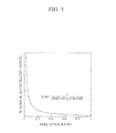
- FIG. 3 is a graph illustrating an example of a relationship between a wear acceleration index and a free space ratio.
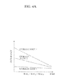
- FIGS. 4A to 4C are graphs illustrating examples of wear management policies.
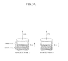
- FIGS. 5A to 5B are diagrams illustrating examples of methods of adjusting wear acceleration indexes of storage nodes.
- FIG. 6 is a flowchart illustrating an example of a wear management method.
- FIG. 1 is a block diagram illustrating an example of a storage system 1 including a wear management apparatus 100.
- the storage system 1 further includes storage nodes 200a, 200b and 200c, i.e., storage nodes 1, 2 and 3.
- Each of the storage nodes 200a, 200b and 200c may be a storage medium based on a NAND flash memory, such as a Solid State Disk (SSD), or may be a terminal, such as a computer and a tablet PC, which includes the storage medium to perform distributed processing.
- SSD Solid State Disk
- FIG. 1 illustrates the storage system 1 including the three storage nodes 200a, 200b and 200c for the sake of explanation, but is merely an example, and a number of storage nodes may be more or less than three.
- the wear management apparatus 100 may be included in the storage system 1 as illustrated in FIG. 1 , or may be separately embedded in hardware.
- the wear management apparatus 100 collects status information about each of the storage nodes 200a, 200b and 200c, and sets and adjusts a wear acceleration index of each of the storage nodes 200a, 200b and 200c based on the collected status information, to support wear management of the storage system 1.
- the wear acceleration index is used as a yardstick to evaluate how an erase operation affects a flash memory-based storage medium to be worn out.
- the wear acceleration index is a ratio of an erase operation performed in the storage medium to a corresponding write operation. In other words, the wear acceleration index indicates whether a respective storage node is to be worn out (i.e., whether erase operations are to be performed on the respective node) before, simultaneously with, or after other storage nodes.
- the wear management apparatus 100 sets and adjusts the wear acceleration index of each of the storage nodes 200a, 200b and 200c based on a predetermined wear management policy of the storage system 1. For example, the wear management apparatus 100 predetermines the wear management policy based on a desired performance of the storage system 1, so that the wear acceleration index of each of the storage nodes 200a, 200b and 200c is equal to one another, or is different from one another to wear a predetermined storage node (for example, the storage node 1 200a) before other storage nodes.
- FIG. 2 is a block diagram illustrating an example of the wear management apparatus 100.
- the wear management apparatus 100 includes a monitor unit 110, a wear management unit 120, a policy management unit 130, a data distribution unit 140, and a data transfer unit 150.
- the monitoring unit 110 collects the status information about each of the storage nodes 200a, 200b and 200c.
- the status information may include an overall capacity, an amount of valid data, a distribution of the data, and/or a wear level of the data.
- the overall capacity refers to a capacity for data storage
- the amount of the valid data refers to an amount of the currently-stored data.
- the distribution of the data refers to a physical location of the data
- a wear level of the data refers to an amount of the data that is worn out due to an erase operation.
- An endurance of each of the storage nodes 200a, 200b and 200c may be predicted based on the wear level. The endurance is a value corresponding to, for example, an amount of the data that is not worn out, and/or a number of erase operations that are to be performed to wear the data.
- the wear management unit 120 establishes a wear progress model based on the collected status information.
- the wear progress model is established with respect to the storage nodes 200a, 200b and 200c, and may include one or more graphs as illustrated in FIGS. 4A to 4C described below.
- the wear management unit 120 controls the wear acceleration index of each of the storage nodes 200a, 200b and 200c based on the established wear progress model and the predetermined wear management policy. For example, the wear management unit 120 may control the wear acceleration index by adjusting a free space ratio of each of the storage nodes 200a, 200b and 200.
- FIG. 3 is a graph illustrating an example of a relationship between the wear acceleration index and the free space ratio.
- the wear acceleration index of each of the storage nodes 200a, 200b and 200c is inclined to be in inverse proportion to the free space ratio of each of the storage nodes 200a, 200b and 200c.
- the wear management unit 120 of FIG. 2 decreases the wear acceleration index by increasing the free space ratio, and increases the wear acceleration index by decreasing the free space ratio.
- the wear management unit 130 predetermines the wear management policy based on the desired performance of the storage system 1.
- the wear management policy may include a policy of equally wearing the storage nodes 200a, 200b and 200c, a policy of sequentially wearing a storage node (for example, the storage node 1 200a) including the greatest endurance among the endurances of the storage nodes 200a, 200b and 200c, or a policy of completely wearing a storage node (for example, the storage node 1 200a) including the least endurance among the endurances of the storage nodes 200a, 200b and 200c .
- FIGS. 4A to 4C are graphs illustrating examples of wear management policies. Each of the graphs illustrates the endurance of each of the storage nodes 1, 2 and 3, over time.
- FIG. 4A is a graph illustrating a wear management policy of equally wearing the storage nodes 1, 2 and 3.
- each of the storage nodes 1, 2 and 3 is set to include a wear acceleration index (WAI) based on the endurance of each of the storage nodes 1, 2 and 3, whereby the storage nodes 1, 2 and 3 are worn out almost simultaneously. That is, since the endurance of each of the storage nodes 3, 2 and 1 is respectively greater in sequence, as shown in FIG. 4A , each of the storage nodes 3, 2 and 1 is set to include the wear acceleration index that is respectively greater in sequence, whereby the storage nodes 1, 2, and 3 are worn out at almost the same time.
- WAI wear acceleration index
- FIG. 4B is a graph illustrating a wear management policy of sequentially wearing a storage node including the greatest endurance among the endurances of the storage nodes 1, 2 and 3.
- the storage node including the greatest endurance is set to include the greatest wear acceleration index (WAI) among the wear acceleration indexes of the storage nodes 1, 2 and 3, so that the storage node including the greatest endurance is worn out the fastest.
- WAI wear acceleration index
- the storage node 1 includes the greatest endurance among the endurances of the storage nodes 1, 2, and 3, and thus, is set to include the greatest wear acceleration index among the wear acceleration indexes of the storage nodes 1, 2 and 3, so that the storage node 1 is worn out faster than the storage nodes 2 and 3.
- the storage nodes 1 and 2 are adjusted to include the same wear acceleration index, which is greater than the wear acceleration index of the storage node 3, so that the storage nodes 1 and 2 are worn out faster than the storage node 3.
- the storage nodes 1, 2 and 3 are adjusted to include the same wear acceleration index, so that the storage nodes 1, 2 and 3 are worn out concurrently. This wear management policy is desired when a storage system needs to be entirely replaced.
- FIG. 4C is a graph illustrating a wear management policy of completely wearing a storage node including the least endurance among the endurances of the storage nodes 1, 2 and 3.
- the storage node including the least endurance is set to include the greatest wear acceleration index (WAI) among the wear acceleration indexes of the storage nodes 1, 2 and 3, so that the storage node including the least endurance is worn out the fastest.
- WAI wear acceleration index
- the storage node 3 includes the least endurance among the endurances of the storage nodes 1, 2, and 3, and thus, is set to include the greatest wear acceleration index among the wear acceleration indexes of the storage nodes 1, 2 and 3, so that the storage node 3 is worn out faster than the storage nodes 1 and 2.
- the storage node 3 is replaced with a new storage node.
- the storage node 2 includes the least endurance, and thus, is adjusted to include the greatest wear acceleration index, so that the storage node 2 is worn out faster than the storage node 1 and the new storage node.
- the storage node 2 is replaced with another new storage node. This wear management policy is desired when it is possible and inexpensive to replace each storage node separately, instead of replacing all storage nodes at once.
- FIGS. 5A and 5B are diagrams illustrating examples of methods of adjusting wear acceleration indexes of storage nodes. Referring to FIGS. 1 , 2 , 5A and 5B , the methods of adjusting the wear acceleration indexes of the storage nodes 1 and 2 in the wear management unit 120 will be provided. As illustrated in FIG. 2 , the wear management apparatus 100 further includes the data distribution unit 140 and the data transfer unit 150.
- the data distribution unit 140 stores data in a predetermined storage node (for example, the storage node 1 200a) using a write operation, and deletes the data using a trim operation.
- the wear management unit 120 controls the data distribution unit 140 to store or delete data (e.g., a wear acceleration index (WAI)) in the predetermined storage node based on the established wear progress model and the predetermined wear management policy with respect to the storage nodes 200a, 200b and 200c.
- FIG. 5A illustrates the wear management unit 120 controlling the data distribution unit 140 to perform a write operation in the storage node 2 to increase the wear acceleration index of the storage node 2, and to perform a trim operation in the storage node 1 to reduce the wear acceleration index of the storage node 1.
- the data distribution unit 140 may adjust the wear acceleration index of the storage node 1 or 2 by adjusting a ratio of a free space to a data space in the storage node 1 or 2.
- the data transfer unit 150 moves data from a predetermined storage node (for example, the storage node 1 200a) to another storage node (for example, the storage node 2 200b) using a move operation.
- the wear management unit 120 controls the data transfer unit 150 to move data (e.g., a wear acceleration index (WAI)) from the predetermined storage node to the other storage node based on the established wear progress model and the predetermined wear management policy with respect to the storage nodes 200a, 200b and 200c.
- WAI wear acceleration index
- 5B illustrates the wear management unit 120 controlling the data transfer unit 150 to move data from the storage node 1 to the storage node 2, to decrease the wear acceleration index of the storage node 1 while increasing the wear acceleration index of the storage node 2.
- the data transfer unit 150 may adjust the wear acceleration index of the storage node 1 or 2 by adjusting the ratio of the free space to the data space in the storage node 1 or 2.
- FIG. 6 is a flowchart illustrating an example of a wear management method. Referring to FIG. 6 , the wear management method of the wear management apparatus 100 described in FIGS. 1 , 2 , 5A and 5B will be provided. Since the wear management apparatus 100 is described in detail with reference to FIGS. 1 , 2 , 5A and 5B , further description about the wear management apparatus 100 will not be provided.
- the wear management apparatus 100 collects the status information about each of the storage nodes 200a, 200b and 200c.
- the status information may include an overall capacity, an amount of valid data, a distribution of the data, and/or a wear level of the data.
- the wear management apparatus 100 establishes the wear progress model based on the collected status information in 302.
- the wear progress model is established with respect to the storage nodes 200a, 200b and 200c.
- the wear management apparatus 100 controls the wear acceleration index (WAI) of each of the storage nodes 200a, 200b and 200c based on the established wear progress model and the predetermined wear management policy with respect to the storage nodes 200a, 200b and 200c.
- the wear acceleration index of each of the storage nodes 200a, 200b and 200c may be controlled by adjusting the free space ratio of each of the storage nodes 200a, 200b and 200c.
- the wear acceleration index is in inverse proportion to the free space ratio. Hence, the wear acceleration index is decreased by increasing the free space ratio, and is increased by decreasing the free space ratio.
- the wear management policy may include the policy of equally wearing the storage nodes 200a, 200b and 200c, the policy of sequentially wearing a storage node (for example, the storage node 1 200a) including the greatest endurance among the endurances of the storage nodes 200a, 200b and 200c, or the policy of completely wearing a storage node (for example, the storage node 1 200a) including the least endurance among the endurances of the storage nodes 200a, 200b and 200c.
- the wear acceleration index may be controlled by storing data in a predetermined storage node using the write operation, or by deleting the data from the predetermined storage node using the trim operation. In addition, the wear acceleration index may be controlled by moving data from a predetermined storage node to another storage node.
- the units described herein may be implemented using hardware components and software components.
- the hardware components may include microphones, amplifiers, band-pass filters, audio to digital convertors, and processing devices.
- a processing device may be implemented using one or more general-purpose or special purpose computers, such as, for example, a processor, a controller and an arithmetic logic unit, a digital signal processor, a microcomputer, a field programmable array, a programmable logic unit, a microprocessor or any other device capable of responding to and executing instructions in a defined manner.
- the processing device may run an operating system (OS) and one or more software applications that run on the OS.
- the processing device also may access, store, manipulate, process, and create data in response to execution of the software.
- OS operating system
- a processing device may include multiple processing elements and multiple types of processing elements.
- a processing device may include multiple processors or a processor and a controller.
- different processing configurations are possible, such a parallel processors.
- the software may include a computer program, a piece of code, an instruction, or some combination thereof, that independently or collectively instructs or configures the processing device to operate as desired.
- Software and data may be embodied permanently or temporarily in any type of machine, component, physical or virtual equipment, computer storage medium or device, or in a propagated signal wave capable of providing instructions or data to or being interpreted by the processing device.
- the software also may be distributed over network coupled computer systems so that the software is stored and executed in a distributed fashion.
- the software and data may be stored by one or more computer readable recording mediums.
- the computer readable recording medium may include any data storage device that can store data which can be thereafter read by a computer system or processing device.
- non-transitory computer readable recording medium examples include read-only memory (ROM), random-access memory (RAM), CD-ROMs, magnetic tapes, floppy disks, optical data storage devices.
- ROM read-only memory
- RAM random-access memory
- CD-ROMs compact disc-read only memory
- magnetic tapes magnetic tapes
- floppy disks optical data storage devices.
- functional programs, codes, and code segments accomplishing the examples disclosed herein can be easily construed by programmers skilled in the art to which the examples pertain based on and using the flow diagrams and block diagrams of the figures and their corresponding descriptions as provided herein.
- a terminal described herein may refer to mobile devices such as a cellular phone, a personal digital assistant (PDA), a digital camera, a portable game console, and an MP3 player, a portable/personal multimedia player (PMP), a handheld e-book, a portable laptop PC, a global positioning system (GPS) navigation, a tablet, a sensor, and devices such as a desktop PC, a high definition television (HDTV), an optical disc player, a setup box, a home appliance, and the like that are capable of wireless communication or network communication consistent with that which is disclosed herein.
- mobile devices such as a cellular phone, a personal digital assistant (PDA), a digital camera, a portable game console, and an MP3 player, a portable/personal multimedia player (PMP), a handheld e-book, a portable laptop PC, a global positioning system (GPS) navigation, a tablet, a sensor, and devices such as a desktop PC, a high definition television (HDTV), an optical disc player, a setup box,
- Flash memory devices and/or memory controllers may be included in various types of packages.
- the flash memory devices and/or memory controllers may be embodied using packages such as Package on Packages (PoPs), Ball Grid Arrays (BGAs), Chip Scale Packages (CSPs), Plastic Leaded Chip Carrier (PLCC), Plastic Dual In-Line Package (PDIP), Die in Waffle Pack, Die in Wafer Form, Chip On Board (COB), Ceramic Dual In-Line Package (CERDIP), Plastic Metric Quad Flat Pack (MQFP), Quad Flatpack (QFP), Small Outline Integrated Circuit (SOIC), Shrink Small Outline Package (SSOP), Thin Small Outline (TSOP), Thin Quad Flatpack (TQFP), System In Package (SIP), Multi Chip Package (MCP), Wafer-level Fabricated Package (WFP), Wafer-Level Processed Stack Package (WSP), and the like.
- packages such as Package on Packages (PoPs), Ball Grid Arrays (BGAs), Chip Scale Packages (CSPs),
- the flash memory devices and/or the memory controllers may constitute memory cards.
- the memory controllers may be constructed to communicate with an external device for example, a host using any one of various types of interface protocols such as a Universal Serial Bus (USB), a Multi Media Card (MMC), a Peripheral Component Interconnect-Express (PCI-E), Serial Advanced Technology Attachment (SATA), Parallel ATA (PATA), Small Computer System Interface (SCSI), Enhanced Small Device Interface (ESDI), and Integrated Drive Electronics (IDE).
- USB Universal Serial Bus
- MMC Multi Media Card
- PCI-E Peripheral Component Interconnect-Express
- SATA Serial Advanced Technology Attachment
- PATA Parallel ATA
- SCSI Small Computer System Interface
- ESDI Enhanced Small Device Interface
- IDE Integrated Drive Electronics
- Flash memory devices may be non-volatile memory devices that can maintain stored data even when power is cut off. According to an increase in the use of mobile devices such as a cellular phone, a personal digital assistant (PDA), a digital camera, a portable game console, and an MP3 player, the flash memory devices may be more widely used as data storage and code storage.
- the flash memory devices may be used in home applications such as a high definition television (HDTV), a DVD, a router, and a Global Positioning System (GPS).
- HDMI high definition television
- DVD DVD
- router a Global Positioning System
Landscapes
- Engineering & Computer Science (AREA)
- Theoretical Computer Science (AREA)
- Physics & Mathematics (AREA)
- General Engineering & Computer Science (AREA)
- General Physics & Mathematics (AREA)
- Human Computer Interaction (AREA)
- Quality & Reliability (AREA)
- Techniques For Improving Reliability Of Storages (AREA)
- Control Of Metal Rolling (AREA)
- General Factory Administration (AREA)
Applications Claiming Priority (1)
| Application Number | Priority Date | Filing Date | Title |
|---|---|---|---|
| KR1020120098312A KR20140031688A (ko) | 2012-09-05 | 2012-09-05 | 스토리지 시스템을 위한 마모 관리 장치 및 방법 |
Publications (2)
| Publication Number | Publication Date |
|---|---|
| EP2706452A2 true EP2706452A2 (fr) | 2014-03-12 |
| EP2706452A3 EP2706452A3 (fr) | 2017-05-03 |
Family
ID=49084856
Family Applications (1)
| Application Number | Title | Priority Date | Filing Date |
|---|---|---|---|
| EP13182808.9A Withdrawn EP2706452A3 (fr) | 2012-09-05 | 2013-09-03 | Appareil et procédé de gestion d'usure pour système de stockage |
Country Status (5)
| Country | Link |
|---|---|
| US (1) | US20140068153A1 (fr) |
| EP (1) | EP2706452A3 (fr) |
| JP (1) | JP2014052998A (fr) |
| KR (1) | KR20140031688A (fr) |
| CN (1) | CN103678156A (fr) |
Families Citing this family (7)
| Publication number | Priority date | Publication date | Assignee | Title |
|---|---|---|---|---|
| WO2012060824A1 (fr) | 2010-11-02 | 2012-05-10 | Hewlett-Packard Development Company, L.P. | Gestion de disque dur électronique (ssd) |
| US9740436B2 (en) * | 2014-11-14 | 2017-08-22 | International Business Machines Corporation | Elastic file system management in storage cloud environments |
| US9678677B2 (en) * | 2014-12-09 | 2017-06-13 | Intel Corporation | Determining adjustments to the spare space in a storage device unavailable to a user based on a current consumption profile of a storage device |
| US10474371B1 (en) * | 2016-06-30 | 2019-11-12 | EMC IP Holding Company LLC | Method and apparatus for SSD/flash device replacement policy |
| CN107608859A (zh) * | 2017-09-29 | 2018-01-19 | 郑州云海信息技术有限公司 | 存储系统状态监控方法、装置、设备及计算机存储介质 |
| JP7003169B2 (ja) * | 2020-03-24 | 2022-01-20 | 株式会社日立製作所 | ストレージシステム及びストレージシステムのssdの交換方法 |
| DE112023000002T5 (de) | 2022-05-25 | 2024-01-18 | Hewlett Packard Enterprise Development Lp | System-Verschleiss-Ausgleich |
Family Cites Families (12)
| Publication number | Priority date | Publication date | Assignee | Title |
|---|---|---|---|---|
| KR101122511B1 (ko) * | 2002-10-28 | 2012-03-15 | 쌘디스크 코포레이션 | 비휘발성 저장 시스템들에서 자동 웨어 레벨링 |
| US7418689B2 (en) * | 2005-04-27 | 2008-08-26 | International Business Machines Corporation | Method of generating wiring routes with matching delay in the presence of process variation |
| JP2009003784A (ja) * | 2007-06-22 | 2009-01-08 | Toshiba Corp | 不揮発性メモリの制御装置及び制御方法及び記憶装置 |
| KR100974215B1 (ko) * | 2008-10-02 | 2010-08-06 | 주식회사 하이닉스반도체 | 반도체 스토리지 시스템 및 그 제어 방법 |
| US9063874B2 (en) * | 2008-11-10 | 2015-06-23 | SanDisk Technologies, Inc. | Apparatus, system, and method for wear management |
| US8364923B2 (en) * | 2009-03-30 | 2013-01-29 | Oracle America, Inc. | Data storage system manager and method for managing a data storage system |
| US8479061B2 (en) * | 2009-09-24 | 2013-07-02 | AGIGA Tech | Solid state memory cartridge with wear indication |
| US8214580B2 (en) * | 2009-10-23 | 2012-07-03 | International Business Machines Corporation | Solid state drive with adjustable drive life and capacity |
| US9183134B2 (en) * | 2010-04-22 | 2015-11-10 | Seagate Technology Llc | Data segregation in a storage device |
| WO2012060824A1 (fr) * | 2010-11-02 | 2012-05-10 | Hewlett-Packard Development Company, L.P. | Gestion de disque dur électronique (ssd) |
| US8539139B1 (en) * | 2010-12-17 | 2013-09-17 | Teradota Us, Inc. | Managing device wearout using I/O metering |
| WO2012157029A1 (fr) * | 2011-05-19 | 2012-11-22 | Hitachi, Ltd. | Appareil de contrôle mémoire et procédé de gestion pour un dispositif de stockage du type à semi-conducteur |
-
2012
- 2012-09-05 KR KR1020120098312A patent/KR20140031688A/ko not_active Withdrawn
-
2013
- 2013-05-22 US US13/899,856 patent/US20140068153A1/en not_active Abandoned
- 2013-07-04 JP JP2013140867A patent/JP2014052998A/ja active Pending
- 2013-07-04 CN CN201310278044.6A patent/CN103678156A/zh active Pending
- 2013-09-03 EP EP13182808.9A patent/EP2706452A3/fr not_active Withdrawn
Non-Patent Citations (1)
| Title |
|---|
| None |
Also Published As
| Publication number | Publication date |
|---|---|
| EP2706452A3 (fr) | 2017-05-03 |
| JP2014052998A (ja) | 2014-03-20 |
| KR20140031688A (ko) | 2014-03-13 |
| CN103678156A (zh) | 2014-03-26 |
| US20140068153A1 (en) | 2014-03-06 |
Similar Documents
| Publication | Publication Date | Title |
|---|---|---|
| EP2706452A2 (fr) | Appareil et procédé de gestion d'usure pour système de stockage | |
| US11561730B1 (en) | Selecting paths between a host and a storage system | |
| US9372788B2 (en) | Storage system and method of adjusting spare memory space in storage system | |
| US10409719B2 (en) | User configurable passive background operation | |
| US9710345B2 (en) | Using unused portion of the storage space of physical storage devices configured as a RAID | |
| US20130268922A1 (en) | System for performing firmware updates on a number of drives in an array with minimum interruption to drive i/o operations | |
| KR20140114515A (ko) | 불휘발성 메모리 장치 및 그것의 중복 데이터 제거 방법 | |
| WO2016200412A1 (fr) | Gestion de reproduction de données | |
| CN103597444A (zh) | 按照使用来管理基于闪存的存储上的数据放置 | |
| US10572407B2 (en) | Hybrid data storage array | |
| US8281042B2 (en) | Memory device and management method of memory device | |
| US20100125697A1 (en) | Computing device having storage, apparatus and method of managing storage, and file system recorded recording medium | |
| KR102079939B1 (ko) | 데이터 저장 장치 및 그것의 명령어 스케줄링 방법 | |
| US10146783B2 (en) | Using file element accesses to select file elements in a file system to defragment | |
| WO2016183918A1 (fr) | Procédé et dispositif de traitement d'espace de stockage | |
| US9342246B2 (en) | Host command based read disturb methodology | |
| KR20170064703A (ko) | 모바일 장치를 이용한 호스트 장치의 부팅 방법 | |
| US9746897B2 (en) | Method for controlling a multi-core central processor unit of a device establishing a relationship between device operational parameters and a number of started cores | |
| KR101978256B1 (ko) | 모바일 기기의 데이터 독출 방법 및 이를 이용하는 모바일 기기 | |
| CN106663070B (zh) | 数据储存系统、计算系统、用于控制数据储存系统的方法以及用于控制计算系统的方法 | |
| KR102959033B1 (ko) | Ssd의 가비지 컬렉션 제어 방법 | |
| US20130166611A1 (en) | File system and file storing method | |
| CN105204775A (zh) | 电子装置以及数据写入方法 | |
| KR101401392B1 (ko) | 가변적 cs 운용방법 및 이를 적용한 컴퓨팅 시스템 | |
| JP2015185024A (ja) | ファイルシステム管理装置、ファイルシステム管理装置の制御方法、および制御プログラム |
Legal Events
| Date | Code | Title | Description |
|---|---|---|---|
| PUAI | Public reference made under article 153(3) epc to a published international application that has entered the european phase |
Free format text: ORIGINAL CODE: 0009012 |
|
| AK | Designated contracting states |
Kind code of ref document: A2 Designated state(s): AL AT BE BG CH CY CZ DE DK EE ES FI FR GB GR HR HU IE IS IT LI LT LU LV MC MK MT NL NO PL PT RO RS SE SI SK SM TR |
|
| AX | Request for extension of the european patent |
Extension state: BA ME |
|
| PUAL | Search report despatched |
Free format text: ORIGINAL CODE: 0009013 |
|
| AK | Designated contracting states |
Kind code of ref document: A3 Designated state(s): AL AT BE BG CH CY CZ DE DK EE ES FI FR GB GR HR HU IE IS IT LI LT LU LV MC MK MT NL NO PL PT RO RS SE SI SK SM TR |
|
| AX | Request for extension of the european patent |
Extension state: BA ME |
|
| RIC1 | Information provided on ipc code assigned before grant |
Ipc: G06F 12/02 20060101ALI20170327BHEP Ipc: G06F 3/06 20060101AFI20170327BHEP |
|
| STAA | Information on the status of an ep patent application or granted ep patent |
Free format text: STATUS: THE APPLICATION IS DEEMED TO BE WITHDRAWN |
|
| 18D | Application deemed to be withdrawn |
Effective date: 20171104 |