EP2706542A1 - Sub-high-frequenzumformer mit wassergekühlter wärmeableitung und wärmeableitungsvorrichtung dafür - Google Patents
Sub-high-frequenzumformer mit wassergekühlter wärmeableitung und wärmeableitungsvorrichtung dafür Download PDFInfo
- Publication number
- EP2706542A1 EP2706542A1 EP11867431.6A EP11867431A EP2706542A1 EP 2706542 A1 EP2706542 A1 EP 2706542A1 EP 11867431 A EP11867431 A EP 11867431A EP 2706542 A1 EP2706542 A1 EP 2706542A1
- Authority
- EP
- European Patent Office
- Prior art keywords
- rectifier
- plate
- output plate
- cooling water
- cooling
- Prior art date
- Legal status (The legal status is an assumption and is not a legal conclusion. Google has not performed a legal analysis and makes no representation as to the accuracy of the status listed.)
- Granted
Links
Images




Classifications
-
- H—ELECTRICITY
- H01—ELECTRIC ELEMENTS
- H01F—MAGNETS; INDUCTANCES; TRANSFORMERS; SELECTION OF MATERIALS FOR THEIR MAGNETIC PROPERTIES
- H01F27/00—Details of transformers or inductances, in general
- H01F27/08—Cooling; Ventilating
- H01F27/10—Liquid cooling
- H01F27/16—Water cooling
-
- H—ELECTRICITY
- H01—ELECTRIC ELEMENTS
- H01F—MAGNETS; INDUCTANCES; TRANSFORMERS; SELECTION OF MATERIALS FOR THEIR MAGNETIC PROPERTIES
- H01F27/00—Details of transformers or inductances, in general
- H01F27/28—Coils; Windings; Conductive connections
- H01F27/2876—Cooling
-
- H—ELECTRICITY
- H01—ELECTRIC ELEMENTS
- H01F—MAGNETS; INDUCTANCES; TRANSFORMERS; SELECTION OF MATERIALS FOR THEIR MAGNETIC PROPERTIES
- H01F38/00—Adaptations of transformers or inductances for specific applications or functions
- H01F38/08—High-leakage transformers or inductances
- H01F38/085—Welding transformers
-
- H—ELECTRICITY
- H01—ELECTRIC ELEMENTS
- H01F—MAGNETS; INDUCTANCES; TRANSFORMERS; SELECTION OF MATERIALS FOR THEIR MAGNETIC PROPERTIES
- H01F27/00—Details of transformers or inductances, in general
- H01F27/40—Structural association with built-in electric component, e.g. fuse
- H01F2027/408—Association with diode or rectifier
Definitions
- the present invention relates to a transformer, particularly to a high frequency transformer for spot welders.
- Traditional resistance welding power sources mainly include AC/DC power frequency spot welders controlling a welding current by adjusting the SCR conduction angle, which are technically mature but bulky. As single-phase input power sources, they are limited by high energy consumption, low efficiency, poor dynamic performance as well as low control accuracy.
- intermediate frequency inverter resistance welding emerges, single-phase power supply upgraded to three-phase power supply and transformer operating frequency elevated from 50 HZ to 1000 HZ.
- An intermediate frequency resistance welding machine has a much smaller size and a promoted efficiency.
- a DC power intermediate frequency resistance welding machine has a remarkably improved welding efficiency in comparison with an AC power spot welder, saving energy by 60% ⁇ 70%, but still is quite big and heavy.
- a sub-high frequency inverter spot welder further improves the transformer efficiency (to 5,000-20,000 HZ) and reduces its size and weight on the basis of the intermediate frequency spot welder. It also has better dynamic response, higher control accuracy and smaller size than an intermediate frequency spot welder.
- the inventor has found said traditional high frequency transformer unsatisfactory in that it has cooling difficulties, by reason of which the temperature rises notably as output power increases, and the rectifier diode is prone to damages, making it hard to further improve the output power.
- the inverse transformer in the prior art is bulky and inefficient, unable to meet its requirements of large current and high power.
- the primary object of this invention is to improve transformer output power and reduce its temperature rise at the same time.
- the second object of the present invention is to improve transformer output power and reduce its size at the same time.
- a water cooling sub-high frequency transformer comprises a magnetic core, a primary coil, a secondary coil, a transformer secondary lead terminal, and a rectifier circuit connected with the transformer secondary lead terminal, characterized in that the rectifier circuit comprises a planar rectifier diode, a diode positive terminal lead plate, a rectifier cathode output plate, and a rectifier anode output plate, wherein the rectifier cathode output plate is a center tap of the transformer; the secondary current of the transformer is connected to the rectifier anode output plate after being rectified by the planar rectifier diode, and is output by the rectifier anode output plate; and each of the rectifier diode positive lead plate, the rectifier anode output plate and the rectifier cathode output plate employs a copper plate structure with a certain thickness provided inside with cooling water passages.
- the water cooling sub-high frequency transformer comprises two sub transformers connected in parallel, each comprising one to three groups of primary coils and one to three groups of secondary coils; each group of primary coils comprises three sub coils, and each group of secondary coils comprises two secondary coils each of which has its two ends joined together; the two leads for the respective two ends of each secondary coil are respectively connected to two diode positive terminal lead plates parallel in a vertical direction; the secondary coil center tap terminal is connected to the rectifier cathode output plate at the joining parts of two secondary coils; the two diode positive terminal lead plates are connected with the positive terminals of the planar rectifier diodes, and the negative terminals are connected with the rectifier anode output plate positioned between the two diode positive terminal lead plates, one planar rectifier diode being positioned between the upper diode positive terminal lead plate and the rectifier anode output plate and the other planar rectifier diode being positioned between the lower diode positive terminal lead plate and the rectifier anode output plate, so that the two plan
- the secondary coil is winded with a red copper pipe of a 4 ⁇ 10 mm diameter in communication with the cooling water passages in the rectifier diode positive lead plate, the rectifier anode output plate and the rectifier cathode output plate.
- the secondary coil center tap terminal of the sub transformer is welded to the rectifier cathode output plate, wherein two output terminals are welded to the upper diode positive terminal lead plate and the other two output terminals are welded to the lower diode positive terminal lead plate.
- the diode positive terminal lead plate, the rectifier cathode output plate and the rectifier anode output plate respectively employ a plate structure made of a red copper plate with a thickness of 10 ⁇ 15 mm, wherein through holes provided within each plate structure compose cooling water passages for cooling water circulation flow, and theses cooling water passages communicate with the red copper pipes composing the secondary coils.
- a cooling device comprises a water outlet, a water inlet and cooling water passages in communication with each other, characterized in that the water inlet is provided on the rectifier cathode output plate, the water outlet is provided on the rectifier anode output plate, and the cooling water passages are provided inside the rectifier cathode output plate, the rectifier anode output plate and diode positive terminal lead plate, wherein the rectifier cathode output plate, the rectifier anode output plate and the diode positive terminal lead plate respectively employ a plate structure with a certain thickness, a plurality of through holes are provided inside each of the plate structure to compose cooling water passages for cooling water circulation flow, and theses cooling water passages communicate with red copper pipes that compose transformer secondary coils.
- the cooling water flows from the water inlet on the rectifier cathode output plate into the cooling water passages on the same plate before diverging into three to six streams: two of the separated streams flow out of the cooling water passages on the rectifier cathode plate to enter the cooling water passages on the rectifier anode output plate and then converge at the outlet of the same plate; and, the rest of streams flow out of the cooling water passages on the rectifier cathode plate to enter one group of the cooling water passages on the planar rectifier diode positive plate, get into another group of the cooling water passages on the planar rectifier diode positive plate after separating two of them to get into two or three secondary coils, and afterwards flow into the cooling water passages on the rectifier anode output plate to finally converge at the water outlet on the same plate.
- the cooling water flows from the water inlet on the rectifier cathode output plate into the cooling water passages on the same plate before being separated by said passages into four branches A, B, C and D in parallel connection, flow into the cooling water passages on the rectifier anode output plate and then converge at the water outlet on the same plate to flow out.
- the water passages and conduits in the water cooling device are connected with each other by an insulating rubber tube with a self-locking connector comprising a self-lock head and a self-lock sleeve with an inner diameter smaller than the outer diameter of the rubber tube stretched after being inserted into the self-lock head, and the engaging part between the self-lock head and the rubber tube is provided with two inverted cone slots with acute angle openings, a partially engaging cylindrical surface provided between the slots has an inner diameter larger than that of the rubber tube.
- FIG. 1 shows a water cooling sub-high frequency transformer and its cooling device, comprising: 1. rectifier cathode output plate; 2. rectifier anode output plate; 3. upper diode positive lead plate; 5. upper diode positive lead plate; 4. lower diode positive lead plate; 6. lower diode positive lead plate; 7. transformer center tap; 8. transformer magnetic core; 9. transformer diode positive lead terminal; 10. transformer primary coil; 11. planar rectifier diode; 12. planar rectifier diode; 13. self-locking connector; 14. self-lock head; 15. insulating rubber tube.
- a water cooling sub-high frequency transformer comprises a primary coil (10), secondary coils (9a1, 9a2, 9b1, 9b2, 9c1, 9c2, 9d1, 9d2), and a rectifier circuit connected with the secondary coils, the rectifier circuit comprising planar rectifier diodes (11, 22), diode positive terminal lead plates (3, 4, 5, 6), a rectifier cathode output plate (1), and a rectifier anode output plate (2), wherein the rectifier cathode output plate is a center tap of the transformer; the secondary current of the transformer is connected to the rectifier anode output plate after being rectified by the planar rectifier diode, and is output by the rectifier anode output plate; and each of the rectifier diode positive lead plate, the rectifier anode output plate and the rectifier cathode output plate employs a red copper plate structure with a certain thickness provided inside with cooling water passages.
- the water cooling sub-high frequency transformer comprises two sub transformers connected in parallel, each comprising two groups of primary coils and two groups of secondary coils; each group of primary coils comprises three sub coils, and each group of secondary coils comprises two secondary coils (9a1 and 9a2) each of which has its two ends joined together; the two leads for the respective two ends of each secondary coil are respectively connected to two diode positive terminal lead plates (3, 4) parallel in a vertical direction; the secondary coil center tap terminal (7a) is connected to the rectifier cathode output plate (1) at the joining parts of two secondary coils; the two diode positive terminal lead plates (3, 4) are connected with the positive terminals of the planar rectifier diodes, and the negative terminals are connected with the rectifier anode output plate (2) which, as FIG.
- the secondary coil (9a1, 9a2, 9b1, 9b2, 9c1, 9c2, 9d1, 9d2) is winded with a red copper pipe of a 4 ⁇ 10 mm diameter in communication with the cooling water passages in the rectifier diode positive lead plate, the rectifier anode output plate and the rectifier cathode output plate.
- the two sub transformers are respectively left transformer secondary and right transformer secondary, wherein the center tap terminal (7a) of the two groups of secondary coils (9a1, 9a2, 9b1, 9b2) of the left transformer is welded to the rectifier cathode output plate (1), and the other four lead terminals are welded to the diode positive terminal lead plates (3, 4); and, the cooling water passages inside the two diode positive terminal lead plates, the red copper pipes composing the secondary coils, and the cooling conduits inside the rectifier cathode output plate are in communication with each other.
- the center tap terminal (7b) of the two groups of secondary coils (9a3, 9a4, 9b3, 9b4) of the right transformer is welded to the rectifier cathode output plate (1), and the other four lead terminals are welded to the diode positive terminal lead plates (5, 6); and, the cooling water passages inside the two diode positive terminal lead plates, the red copper pipes composing the secondary coils, and the cooling conduits inside the rectifier cathode output plate are in communication with each other.
- the diode positive terminal lead plates (3, 4, 5, 6), the rectifier cathode output plate (1), and the rectifier anode output plate (2) respectively employ a plate structure made of a red copper plate with a thickness of 10 ⁇ 15 mm, wherein through holes provided inside each plate structure compose cooling water passages for cooling water circulation flow, and theses cooling water passages communicate with the red copper pipes composing the secondary coils.
- a cooling device comprises a water outlet provided on the rectifier anode output plate (Z2), a water inlet provided on the rectifier cathode output plate (Z1), and cooling water passages provided inside the rectifier cathode output plate, the rectifier anode output plate and diode positive terminal lead plate in communication with each other, wherein the rectifier cathode output plate, the rectifier anode output plate and the diode positive terminal lead plate respectively employ a plate structure with a certain thickness, a plurality of through holes are provided inside each of the plate structure to compose cooling water passages for cooling water circulation flow, and theses cooling water passages communicate with red copper pipes that compose transformer secondary coils.
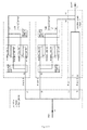
- FIG. 2 shows a flow chart of cooling water in the cooling device: the cooling water under 0.3 Mpa pressure flows from the water inlet (Z1) of the rectifier cathode output plate into the rectifier cathode output plate before being separated by the waterways in the rectifier cathode output plate into four branches A, B, C and D in parallel connection, then flows into the rectifier anode output plate, and finally converges to flow out.
- Branch B it enters a right passage of the rectifier cathode output plate 1 from the inlet (Z1) of the same plate and leaves from its outlet (B1), then flows into the inlet (B2) of the diode positive terminal lead plate 5 and diverges into two streams in the diode positive terminal lead plate 5, one flowing directly into the secondary coils (9c1, 9c2) (to bring away the heat of the secondary and primary coils), then into the diode positive terminal lead plate 6, and flowing through the waterways inside the diode positive terminal lead plate 6 (to bring away part of the heat of the diode positive terminal lead plate 6) to reach the outlet (B3) of the same plate and then into the inlet (A4) of the rectifier anode output plate 2, the other stream entering the secondary coils (9d1, 9d2) via the waterways in the diode positive terminal lead plate 5(to bring away the heat of the lead plate 5), passing through the secondary coils (to bring away the heat of the secondary and primary
- Branch C it enters a left passage of the rectifier cathode output plate 1 from the inlet (Z1) of the same plate and leaves from its outlet (A3), then flows into the inlet (A4) of the rectifier anode output plate 2, and passes through left waterways of the rectifier anode output plate (to bring away the heat of the left rectifier diode positive) to flow out from the outlet (Z2) of the rectifier anode output plate;
- Branch C it enters a right passage of the rectifier cathode output plate 1 from the inlet (Z1) of the same plate and leaves from its outlet (B3), then flows into the inlet (B4) of the rectifier anode output plate 2, and passes through right waterways of the rectifier anode output plate (to bring away the heat of the right rectifier diode positive) to flow out from the outlet (Z2) of the rectifier anode output plate.
- FIG. 2 and 7 show, in the rectifier, the waterway connections between the rectifier anode plate, the rectifier cathode plate and the diode positive lead, and between the above and the red copper pipes composing the secondary coils are achieved by insulating rubber tubes (with an outer diameter of 13 mm and an inner diameter of 6.5 mm) using a self-locking connector comprising a self-lock head (13) and a self-lock sleeve (14).
- the engaging part between the self-lock head and the rubber tube (15) is provided with two inverted cone slots with acute angle openings, and a partially engaging cylindrical surface is provided between the slots, the inner diameter of the cylindrical surface being larger than that of the rubber tube by 1.8 mm and the inner diameter of the self-lock sleeve being smaller than the outer diameter of the rubber tube stretched after being inserted into the self-lock head by 0.2 mm.
- FIG. 7 shows the assembly of the rubber tube wherein the rubber tube is sleeved on the self-lock head to tightly enwrap the self-lock head, and the cylindrical surface is perfectly engaged to the rubber tuber to ensure the connection tightness.
- the self-lock sleeve is 0.2 mm smaller than the stretched rubber tube so as to, when being sleeved on the rubber tube stretched to open up, compress the rubber tube to prevent it from expanding outward. Meanwhile, part of the rubber is embedded in the inverted cone slots of the self-lock head to prevent the rubber tube from coming off.
- the magnetic core has a temperature controlled under 60°C and the rectifier diode has a temperature controlled under 80°C.
- the system has a temperature sensor monitor to ensure that the transformer bulk temperature decreases substantially and the output current fluctuates in a small range. Therefore, the influence of temperature rise on the transformer is reduced.
- the present invention narrows the interspaces inside the transformer where the waterways get connected. Thereby the transformer size is somewhat reduced and the waterway connection tightness is ensured at the same time.
- the transformer of this invention uses only four planar rectifier diodes to output a current of 12000 A, and has the dimensions of 300 mm*168 mm*100 mm much smaller than a traditional transformer.
Landscapes
- Engineering & Computer Science (AREA)
- Power Engineering (AREA)
- Rectifiers (AREA)
Applications Claiming Priority (1)
| Application Number | Priority Date | Filing Date | Title |
|---|---|---|---|
| PCT/CN2011/075454 WO2012167428A1 (zh) | 2011-06-08 | 2011-06-08 | 水冷散热次高频变压器及其散热装置 |
Publications (3)
| Publication Number | Publication Date |
|---|---|
| EP2706542A1 true EP2706542A1 (de) | 2014-03-12 |
| EP2706542A4 EP2706542A4 (de) | 2014-05-07 |
| EP2706542B1 EP2706542B1 (de) | 2016-03-16 |
Family
ID=47295341
Family Applications (1)
| Application Number | Title | Priority Date | Filing Date |
|---|---|---|---|
| EP11867431.6A Active EP2706542B1 (de) | 2011-06-08 | 2011-06-08 | Unter-hoch-frequenzumformer mit wassergekühlter wärmeableitung |
Country Status (4)
| Country | Link |
|---|---|
| US (1) | US20140104912A1 (de) |
| EP (1) | EP2706542B1 (de) |
| CN (1) | CN103299377A (de) |
| WO (1) | WO2012167428A1 (de) |
Families Citing this family (1)
| Publication number | Priority date | Publication date | Assignee | Title |
|---|---|---|---|---|
| CN112820515B (zh) * | 2021-01-08 | 2022-03-11 | 合肥三宇电器有限责任公司 | 一种低压大电流的电源装置 |
Family Cites Families (20)
| Publication number | Priority date | Publication date | Assignee | Title |
|---|---|---|---|---|
| CH673188A5 (de) * | 1987-08-03 | 1990-02-15 | Schlatter Ag | |
| JP2672238B2 (ja) * | 1992-11-06 | 1997-11-05 | 本田技研工業株式会社 | 溶接機用トランス |
| CN2262280Y (zh) * | 1995-12-11 | 1997-09-10 | 江苏省建湖县电子器材厂 | 新型隔离变压器 |
| JP4085362B2 (ja) * | 2002-05-23 | 2008-05-14 | 東海ゴム工業株式会社 | 接続確認機能付きクイックコネクタ |
| JP2005274120A (ja) * | 2004-02-24 | 2005-10-06 | Showa Denko Kk | 液冷式冷却板 |
| DE102004030845A1 (de) * | 2004-06-25 | 2006-01-12 | Harms & Wende Gmbh U. Co Kg | Schweißstromwandler |
| CN1787129A (zh) * | 2004-12-10 | 2006-06-14 | 中山市怡能电气有限公司 | 高频开关变压器 |
| CN200979295Y (zh) * | 2006-11-13 | 2007-11-21 | 郦洪武 | 变压器磁通量可调的电热水器 |
| JP2008130657A (ja) * | 2006-11-17 | 2008-06-05 | Obara Corp | インバータトランスの外皮冷却構造 |
| CN101364471B (zh) * | 2007-08-08 | 2011-06-08 | 深圳市宝安联华实业有限公司 | 手持式中高频感应加热设备的工作变压器及制作方法 |
| CA2740972C (en) * | 2008-10-15 | 2018-05-29 | John Swift | Building-integrated solar thermal micro-channel absorber and method of manufacturing thereof |
| US8955552B2 (en) * | 2009-07-24 | 2015-02-17 | Parker-Hannifin Corporation | Fire resistant hose assembly |
| CN101630917A (zh) * | 2009-08-20 | 2010-01-20 | 石新春 | 一体化高频整流装置 |
| JP4687930B2 (ja) * | 2009-09-10 | 2011-05-25 | 株式会社向洋技研 | 溶接トランス |
| CN101645659B (zh) * | 2009-09-21 | 2011-06-22 | 鹏煜威科技(深圳)有限公司 | 一种整流组件及次级整流变压器 |
| DE202009012960U1 (de) * | 2009-09-25 | 2009-12-03 | Nimak Gmbh | Stromquelle für ein Widerstandsschweißgerät |
| CN101800123B (zh) * | 2010-03-23 | 2012-07-11 | 深圳市鸿栢科技实业有限公司 | 一种电阻焊高频变压器 |
| CN201796715U (zh) * | 2010-03-23 | 2011-04-13 | 深圳市鸿栢科技实业有限公司 | 一种电阻焊高频变压器 |
| WO2011159323A1 (en) * | 2010-06-14 | 2011-12-22 | Parker-Hannifin Corporation | High voltage power supply system and method |
| CN202632963U (zh) * | 2011-06-08 | 2012-12-26 | 深圳市鸿栢科技实业有限公司 | 水冷散热次高频变压器及其散热装置 |
-
2011
- 2011-06-08 CN CN2011800412928A patent/CN103299377A/zh active Pending
- 2011-06-08 EP EP11867431.6A patent/EP2706542B1/de active Active
- 2011-06-08 WO PCT/CN2011/075454 patent/WO2012167428A1/zh not_active Ceased
- 2011-06-08 US US14/119,923 patent/US20140104912A1/en not_active Abandoned
Also Published As
| Publication number | Publication date |
|---|---|
| EP2706542B1 (de) | 2016-03-16 |
| US20140104912A1 (en) | 2014-04-17 |
| WO2012167428A1 (zh) | 2012-12-13 |
| EP2706542A4 (de) | 2014-05-07 |
| CN103299377A (zh) | 2013-09-11 |
Similar Documents
| Publication | Publication Date | Title |
|---|---|---|
| WO2011116544A1 (zh) | 一种电阻焊高频变压器及点焊机 | |
| CN103366932B (zh) | 中高频变压器 | |
| KR102761943B1 (ko) | 저압 고전류의 전원장치 | |
| TW201325057A (zh) | 一種直流轉直流的電壓調節裝置及其操作方法 | |
| EP2706542B1 (de) | Unter-hoch-frequenzumformer mit wassergekühlter wärmeableitung | |
| CN102956350A (zh) | 一种一体化高频功率变压器 | |
| CN108809114B (zh) | 逆变电阻焊机电源 | |
| CN201466976U (zh) | 一体化高频整流装置 | |
| CN202169436U (zh) | 水冷散热高频变压器及其散热装置 | |
| CN202268252U (zh) | 电容器芯子组并联连接结构 | |
| CN104901551A (zh) | 高功率密度低压输出同步整流电源模块 | |
| CN208836010U (zh) | 逆变电阻焊机电源 | |
| CN106300990B (zh) | 双变压器结构的有源嵌位正激dc/dc变换器拓扑电路 | |
| JP3186715U (ja) | 大電流用整流器 | |
| CN201796715U (zh) | 一种电阻焊高频变压器 | |
| CN207587511U (zh) | 一种铝焊接大功率中频变压器 | |
| CN210837411U (zh) | 免维护水冷电抗器及其便于装配的水冷系统 | |
| CN110444367B (zh) | 一种用于感应加热的同轴变压器 | |
| CN203951373U (zh) | 一种大功率螺柱焊机的单逆变电源结构 | |
| CN221466424U (zh) | 一种中频电阻焊变压器 | |
| KR101508247B1 (ko) | 콤팩트화된 대용량정류기시스템 | |
| CN203085338U (zh) | 一种一体化高频功率变压器 | |
| KR20140002406A (ko) | 변압기용 별치식 방열기 | |
| CN104734101B (zh) | 特高压直流融冰装置高压大电流变流系统结构 | |
| CN207135332U (zh) | 一种输出不同电流等级的led灯恒流电源 |
Legal Events
| Date | Code | Title | Description |
|---|---|---|---|
| PUAI | Public reference made under article 153(3) epc to a published international application that has entered the european phase |
Free format text: ORIGINAL CODE: 0009012 |
|
| 17P | Request for examination filed |
Effective date: 20131205 |
|
| AK | Designated contracting states |
Kind code of ref document: A1 Designated state(s): AL AT BE BG CH CY CZ DE DK EE ES FI FR GB GR HR HU IE IS IT LI LT LU LV MC MK MT NL NO PL PT RO RS SE SI SK SM TR |
|
| A4 | Supplementary search report drawn up and despatched |
Effective date: 20140407 |
|
| RIC1 | Information provided on ipc code assigned before grant |
Ipc: H01F 27/40 20060101ALI20140401BHEP Ipc: H01F 27/28 20060101AFI20140401BHEP Ipc: H01F 27/16 20060101ALI20140401BHEP |
|
| DAX | Request for extension of the european patent (deleted) | ||
| 17Q | First examination report despatched |
Effective date: 20150130 |
|
| GRAP | Despatch of communication of intention to grant a patent |
Free format text: ORIGINAL CODE: EPIDOSNIGR1 |
|
| INTG | Intention to grant announced |
Effective date: 20150917 |
|
| GRAS | Grant fee paid |
Free format text: ORIGINAL CODE: EPIDOSNIGR3 |
|
| GRAA | (expected) grant |
Free format text: ORIGINAL CODE: 0009210 |
|
| AK | Designated contracting states |
Kind code of ref document: B1 Designated state(s): AL AT BE BG CH CY CZ DE DK EE ES FI FR GB GR HR HU IE IS IT LI LT LU LV MC MK MT NL NO PL PT RO RS SE SI SK SM TR |
|
| REG | Reference to a national code |
Ref country code: GB Ref legal event code: FG4D |
|
| REG | Reference to a national code |
Ref country code: CH Ref legal event code: EP |
|
| REG | Reference to a national code |
Ref country code: IE Ref legal event code: FG4D |
|
| REG | Reference to a national code |
Ref country code: AT Ref legal event code: REF Ref document number: 781850 Country of ref document: AT Kind code of ref document: T Effective date: 20160415 |
|
| REG | Reference to a national code |
Ref country code: DE Ref legal event code: R096 Ref document number: 602011024200 Country of ref document: DE |
|
| REG | Reference to a national code |
Ref country code: FR Ref legal event code: PLFP Year of fee payment: 6 |
|
| REG | Reference to a national code |
Ref country code: NL Ref legal event code: MP Effective date: 20160316 |
|
| REG | Reference to a national code |
Ref country code: LT Ref legal event code: MG4D |
|
| PG25 | Lapsed in a contracting state [announced via postgrant information from national office to epo] |
Ref country code: FI Free format text: LAPSE BECAUSE OF FAILURE TO SUBMIT A TRANSLATION OF THE DESCRIPTION OR TO PAY THE FEE WITHIN THE PRESCRIBED TIME-LIMIT Effective date: 20160316 Ref country code: NO Free format text: LAPSE BECAUSE OF FAILURE TO SUBMIT A TRANSLATION OF THE DESCRIPTION OR TO PAY THE FEE WITHIN THE PRESCRIBED TIME-LIMIT Effective date: 20160616 Ref country code: HR Free format text: LAPSE BECAUSE OF FAILURE TO SUBMIT A TRANSLATION OF THE DESCRIPTION OR TO PAY THE FEE WITHIN THE PRESCRIBED TIME-LIMIT Effective date: 20160316 Ref country code: GR Free format text: LAPSE BECAUSE OF FAILURE TO SUBMIT A TRANSLATION OF THE DESCRIPTION OR TO PAY THE FEE WITHIN THE PRESCRIBED TIME-LIMIT Effective date: 20160617 |
|
| REG | Reference to a national code |
Ref country code: AT Ref legal event code: MK05 Ref document number: 781850 Country of ref document: AT Kind code of ref document: T Effective date: 20160316 |
|
| PG25 | Lapsed in a contracting state [announced via postgrant information from national office to epo] |
Ref country code: LT Free format text: LAPSE BECAUSE OF FAILURE TO SUBMIT A TRANSLATION OF THE DESCRIPTION OR TO PAY THE FEE WITHIN THE PRESCRIBED TIME-LIMIT Effective date: 20160316 Ref country code: RS Free format text: LAPSE BECAUSE OF FAILURE TO SUBMIT A TRANSLATION OF THE DESCRIPTION OR TO PAY THE FEE WITHIN THE PRESCRIBED TIME-LIMIT Effective date: 20160316 Ref country code: LV Free format text: LAPSE BECAUSE OF FAILURE TO SUBMIT A TRANSLATION OF THE DESCRIPTION OR TO PAY THE FEE WITHIN THE PRESCRIBED TIME-LIMIT Effective date: 20160316 Ref country code: NL Free format text: LAPSE BECAUSE OF FAILURE TO SUBMIT A TRANSLATION OF THE DESCRIPTION OR TO PAY THE FEE WITHIN THE PRESCRIBED TIME-LIMIT Effective date: 20160316 Ref country code: SE Free format text: LAPSE BECAUSE OF FAILURE TO SUBMIT A TRANSLATION OF THE DESCRIPTION OR TO PAY THE FEE WITHIN THE PRESCRIBED TIME-LIMIT Effective date: 20160316 |
|
| PG25 | Lapsed in a contracting state [announced via postgrant information from national office to epo] |
Ref country code: PL Free format text: LAPSE BECAUSE OF FAILURE TO SUBMIT A TRANSLATION OF THE DESCRIPTION OR TO PAY THE FEE WITHIN THE PRESCRIBED TIME-LIMIT Effective date: 20160316 Ref country code: IS Free format text: LAPSE BECAUSE OF FAILURE TO SUBMIT A TRANSLATION OF THE DESCRIPTION OR TO PAY THE FEE WITHIN THE PRESCRIBED TIME-LIMIT Effective date: 20160716 Ref country code: EE Free format text: LAPSE BECAUSE OF FAILURE TO SUBMIT A TRANSLATION OF THE DESCRIPTION OR TO PAY THE FEE WITHIN THE PRESCRIBED TIME-LIMIT Effective date: 20160316 |
|
| PG25 | Lapsed in a contracting state [announced via postgrant information from national office to epo] |
Ref country code: SK Free format text: LAPSE BECAUSE OF FAILURE TO SUBMIT A TRANSLATION OF THE DESCRIPTION OR TO PAY THE FEE WITHIN THE PRESCRIBED TIME-LIMIT Effective date: 20160316 Ref country code: RO Free format text: LAPSE BECAUSE OF FAILURE TO SUBMIT A TRANSLATION OF THE DESCRIPTION OR TO PAY THE FEE WITHIN THE PRESCRIBED TIME-LIMIT Effective date: 20160316 Ref country code: PT Free format text: LAPSE BECAUSE OF FAILURE TO SUBMIT A TRANSLATION OF THE DESCRIPTION OR TO PAY THE FEE WITHIN THE PRESCRIBED TIME-LIMIT Effective date: 20160718 Ref country code: AT Free format text: LAPSE BECAUSE OF FAILURE TO SUBMIT A TRANSLATION OF THE DESCRIPTION OR TO PAY THE FEE WITHIN THE PRESCRIBED TIME-LIMIT Effective date: 20160316 Ref country code: SM Free format text: LAPSE BECAUSE OF FAILURE TO SUBMIT A TRANSLATION OF THE DESCRIPTION OR TO PAY THE FEE WITHIN THE PRESCRIBED TIME-LIMIT Effective date: 20160316 Ref country code: CZ Free format text: LAPSE BECAUSE OF FAILURE TO SUBMIT A TRANSLATION OF THE DESCRIPTION OR TO PAY THE FEE WITHIN THE PRESCRIBED TIME-LIMIT Effective date: 20160316 Ref country code: ES Free format text: LAPSE BECAUSE OF FAILURE TO SUBMIT A TRANSLATION OF THE DESCRIPTION OR TO PAY THE FEE WITHIN THE PRESCRIBED TIME-LIMIT Effective date: 20160316 |
|
| REG | Reference to a national code |
Ref country code: DE Ref legal event code: R097 Ref document number: 602011024200 Country of ref document: DE |
|
| PG25 | Lapsed in a contracting state [announced via postgrant information from national office to epo] |
Ref country code: IT Free format text: LAPSE BECAUSE OF FAILURE TO SUBMIT A TRANSLATION OF THE DESCRIPTION OR TO PAY THE FEE WITHIN THE PRESCRIBED TIME-LIMIT Effective date: 20160316 Ref country code: BE Free format text: LAPSE BECAUSE OF FAILURE TO SUBMIT A TRANSLATION OF THE DESCRIPTION OR TO PAY THE FEE WITHIN THE PRESCRIBED TIME-LIMIT Effective date: 20160316 |
|
| PLBE | No opposition filed within time limit |
Free format text: ORIGINAL CODE: 0009261 |
|
| STAA | Information on the status of an ep patent application or granted ep patent |
Free format text: STATUS: NO OPPOSITION FILED WITHIN TIME LIMIT |
|
| PG25 | Lapsed in a contracting state [announced via postgrant information from national office to epo] |
Ref country code: DK Free format text: LAPSE BECAUSE OF FAILURE TO SUBMIT A TRANSLATION OF THE DESCRIPTION OR TO PAY THE FEE WITHIN THE PRESCRIBED TIME-LIMIT Effective date: 20160316 Ref country code: MC Free format text: LAPSE BECAUSE OF FAILURE TO SUBMIT A TRANSLATION OF THE DESCRIPTION OR TO PAY THE FEE WITHIN THE PRESCRIBED TIME-LIMIT Effective date: 20160316 |
|
| REG | Reference to a national code |
Ref country code: CH Ref legal event code: PL |
|
| 26N | No opposition filed |
Effective date: 20161219 |
|
| PG25 | Lapsed in a contracting state [announced via postgrant information from national office to epo] |
Ref country code: BG Free format text: LAPSE BECAUSE OF FAILURE TO SUBMIT A TRANSLATION OF THE DESCRIPTION OR TO PAY THE FEE WITHIN THE PRESCRIBED TIME-LIMIT Effective date: 20160616 |
|
| GBPC | Gb: european patent ceased through non-payment of renewal fee |
Effective date: 20160616 |
|
| REG | Reference to a national code |
Ref country code: IE Ref legal event code: MM4A |
|
| PG25 | Lapsed in a contracting state [announced via postgrant information from national office to epo] |
Ref country code: CH Free format text: LAPSE BECAUSE OF NON-PAYMENT OF DUE FEES Effective date: 20160630 Ref country code: LI Free format text: LAPSE BECAUSE OF NON-PAYMENT OF DUE FEES Effective date: 20160630 |
|
| PG25 | Lapsed in a contracting state [announced via postgrant information from national office to epo] |
Ref country code: IE Free format text: LAPSE BECAUSE OF NON-PAYMENT OF DUE FEES Effective date: 20160608 Ref country code: SI Free format text: LAPSE BECAUSE OF FAILURE TO SUBMIT A TRANSLATION OF THE DESCRIPTION OR TO PAY THE FEE WITHIN THE PRESCRIBED TIME-LIMIT Effective date: 20160316 Ref country code: GB Free format text: LAPSE BECAUSE OF NON-PAYMENT OF DUE FEES Effective date: 20160616 |
|
| REG | Reference to a national code |
Ref country code: FR Ref legal event code: PLFP Year of fee payment: 7 |
|
| PG25 | Lapsed in a contracting state [announced via postgrant information from national office to epo] |
Ref country code: CY Free format text: LAPSE BECAUSE OF FAILURE TO SUBMIT A TRANSLATION OF THE DESCRIPTION OR TO PAY THE FEE WITHIN THE PRESCRIBED TIME-LIMIT Effective date: 20160316 Ref country code: HU Free format text: LAPSE BECAUSE OF FAILURE TO SUBMIT A TRANSLATION OF THE DESCRIPTION OR TO PAY THE FEE WITHIN THE PRESCRIBED TIME-LIMIT; INVALID AB INITIO Effective date: 20110608 |
|
| REG | Reference to a national code |
Ref country code: FR Ref legal event code: PLFP Year of fee payment: 8 |
|
| PG25 | Lapsed in a contracting state [announced via postgrant information from national office to epo] |
Ref country code: LU Free format text: LAPSE BECAUSE OF NON-PAYMENT OF DUE FEES Effective date: 20160608 Ref country code: MT Free format text: LAPSE BECAUSE OF NON-PAYMENT OF DUE FEES Effective date: 20160630 Ref country code: TR Free format text: LAPSE BECAUSE OF FAILURE TO SUBMIT A TRANSLATION OF THE DESCRIPTION OR TO PAY THE FEE WITHIN THE PRESCRIBED TIME-LIMIT Effective date: 20160316 Ref country code: MK Free format text: LAPSE BECAUSE OF FAILURE TO SUBMIT A TRANSLATION OF THE DESCRIPTION OR TO PAY THE FEE WITHIN THE PRESCRIBED TIME-LIMIT Effective date: 20160316 |
|
| PG25 | Lapsed in a contracting state [announced via postgrant information from national office to epo] |
Ref country code: AL Free format text: LAPSE BECAUSE OF FAILURE TO SUBMIT A TRANSLATION OF THE DESCRIPTION OR TO PAY THE FEE WITHIN THE PRESCRIBED TIME-LIMIT Effective date: 20160316 |
|
| REG | Reference to a national code |
Ref country code: DE Ref legal event code: R082 Ref document number: 602011024200 Country of ref document: DE Representative=s name: SUN, YIMING, M.SC. DIPL. SC. POL. UNIV., DE |
|
| PGFP | Annual fee paid to national office [announced via postgrant information from national office to epo] |
Ref country code: DE Payment date: 20250617 Year of fee payment: 15 |
|
| PGFP | Annual fee paid to national office [announced via postgrant information from national office to epo] |
Ref country code: FR Payment date: 20250630 Year of fee payment: 15 |