EP2707100B1 - Vorrichtung zur teilchenstrahl-reichweitenprüfung - Google Patents
Vorrichtung zur teilchenstrahl-reichweitenprüfung Download PDFInfo
- Publication number
- EP2707100B1 EP2707100B1 EP12729008.8A EP12729008A EP2707100B1 EP 2707100 B1 EP2707100 B1 EP 2707100B1 EP 12729008 A EP12729008 A EP 12729008A EP 2707100 B1 EP2707100 B1 EP 2707100B1
- Authority
- EP
- European Patent Office
- Prior art keywords
- camera
- target
- line
- predicted
- slit
- Prior art date
- Legal status (The legal status is an assumption and is not a legal conclusion. Google has not performed a legal analysis and makes no representation as to the accuracy of the status listed.)
- Active
Links
Images


Classifications
-
- A—HUMAN NECESSITIES
- A61—MEDICAL OR VETERINARY SCIENCE; HYGIENE
- A61N—ELECTROTHERAPY; MAGNETOTHERAPY; RADIATION THERAPY; ULTRASOUND THERAPY
- A61N5/00—Radiation therapy
- A61N5/10—X-ray therapy; Gamma-ray therapy; Particle-irradiation therapy
- A61N5/1048—Monitoring, verifying, controlling systems and methods
-
- A—HUMAN NECESSITIES
- A61—MEDICAL OR VETERINARY SCIENCE; HYGIENE
- A61N—ELECTROTHERAPY; MAGNETOTHERAPY; RADIATION THERAPY; ULTRASOUND THERAPY
- A61N5/00—Radiation therapy
- A61N5/10—X-ray therapy; Gamma-ray therapy; Particle-irradiation therapy
- A61N5/1048—Monitoring, verifying, controlling systems and methods
- A61N5/1064—Monitoring, verifying, controlling systems and methods for adjusting radiation treatment in response to monitoring
- A61N5/1065—Beam adjustment
-
- G—PHYSICS
- G01—MEASURING; TESTING
- G01T—MEASUREMENT OF NUCLEAR OR X-RADIATION
- G01T1/00—Measuring X-radiation, gamma radiation, corpuscular radiation, or cosmic radiation
- G01T1/29—Measurement performed on radiation beams, e.g. position or section of the beam; Measurement of spatial distribution of radiation
- G01T1/2914—Measurement of spatial distribution of radiation
-
- A—HUMAN NECESSITIES
- A61—MEDICAL OR VETERINARY SCIENCE; HYGIENE
- A61N—ELECTROTHERAPY; MAGNETOTHERAPY; RADIATION THERAPY; ULTRASOUND THERAPY
- A61N5/00—Radiation therapy
- A61N5/10—X-ray therapy; Gamma-ray therapy; Particle-irradiation therapy
- A61N5/1048—Monitoring, verifying, controlling systems and methods
- A61N5/1049—Monitoring, verifying, controlling systems and methods for verifying the position of the patient with respect to the radiation beam
- A61N2005/1052—Monitoring, verifying, controlling systems and methods for verifying the position of the patient with respect to the radiation beam using positron emission tomography [PET] single photon emission computer tomography [SPECT] imaging
-
- A—HUMAN NECESSITIES
- A61—MEDICAL OR VETERINARY SCIENCE; HYGIENE
- A61N—ELECTROTHERAPY; MAGNETOTHERAPY; RADIATION THERAPY; ULTRASOUND THERAPY
- A61N5/00—Radiation therapy
- A61N5/10—X-ray therapy; Gamma-ray therapy; Particle-irradiation therapy
- A61N2005/1085—X-ray therapy; Gamma-ray therapy; Particle-irradiation therapy characterised by the type of particles applied to the patient
- A61N2005/1087—Ions; Protons
Definitions
- the invention is related to the field of charged Hadron Therapy, i.e. radiation therapy using particles, such as protons or ions (e.g. carbon ions). More particularly, the invention is related to the measurement of the beam range of a charged hadron beam in a target object.
- charged Hadron Therapy i.e. radiation therapy using particles, such as protons or ions (e.g. carbon ions). More particularly, the invention is related to the measurement of the beam range of a charged hadron beam in a target object.
- hadrons i.e., protons, pions, ions such as carbon ions
- protons of a given energy i.e. forming a mono-energetic proton beam
- Bragg Peak which defines said penetration depth, i.e. the point of greatest penetration of the radiation in the target volume.
- the position of the Bragg peak is also referred as the 'beam range'.
- the Bragg peak position depends on the energy of the hadron beam, it is evident that by precisely controlling and modifying the energy, one can place the Bragg Peak at a given depth of a tumour so as to administer the greatest radiation energy to selected points and spare the healthy tissue surrounding said points.
- the location of the Bragg peak must be precisely controlled since critical tissue localized near the target tumour could receive overdoses, whereas conversely the target tumour could receive underdoses, in case of range error.
- a direct on-line i.e. during beam delivery, measurement of the particle range.
- Document EP2140913 discloses an apparatus wherein a pin-hole camera is used in conjunction with a scintillator and a 2-dimensional array of photodetectors. Such an apparatus allows to detect the dose fall-off region without requiring a movement of the detectors with respect to the target.
- the invention is related to an apparatus for verifying the beam range in a target irradiated with a charged hadron beam, such as a proton beam as disclosed in the appended claims.
- the beam range is the location of the Bragg peak in the target, being the location where the largest portion of the dose is delivered.
- the method utilizes a prompt gamma camera provided with a slit-shaped opening, so as to be able to produce a 1-dimensional profile of the dose distribution along the beam line.
- the camera is mounted with the slit oriented perpendicularly to the beam line.
- the method comprises the steps of calculating a position of the camera with respect to a target, for a plurality of beam energies and spots to be irradiated.
- the method further comprises the steps of verifying the beam range for said plurality of spots, and delivering a value representative of the difference between the estimated beam range and the actual beam range.
- the apparatus of the invention is provided with a positioning module for positioning the camera.
- the invention is related to an apparatus for verifying the beam range in a target irradiated by a charged hadron beam, in an installation comprising:
- said verification module may further be configured to provide a second output representative of the difference between the predicted deposited dose and the dose as measured by the camera positioned in said position.
- An apparatus of the invention may further comprise an actuation module, configured to receive a signal representative of said difference or differences, and configured to apply on the basis of said signal, corrective measures to one or more parameters of the irradiation installation, during the irradiation of a target or after irradiation of a target.
- an actuation module configured to receive a signal representative of said difference or differences, and configured to apply on the basis of said signal, corrective measures to one or more parameters of the irradiation installation, during the irradiation of a target or after irradiation of a target.
- the apparatus of the invention is suitable for operation with an irradiation installation comprising a rotatable gantry, wherein said positioning module comprises a means for rotating the camera around a rotational axis that coincides with the rotation axis of the gantry, and a means for moving the camera linearly in the direction of said rotation axis of the gantry.
- said positioning module comprises a robotic arm onto which the camera is mounted, so that the camera can be moved with six degrees of freedom.
- said positioning module comprises a means for moving the camera with respect to a target, along a trajectory that is fixed with respect to said target.
- said positioning module comprises an arm extending in a direction parallel to the beam line of a beam produced by the nozzle, said arm, whilst remaining parallel to said beam line, being configured to:
- the apparatus may comprise a plate that is rotatable about the beam line, wherein said arm is slidably arranged in a block which is movable in the radial direction of the plate.
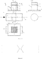
- FIG. 1 shows an embodiment of a camera that is applicable in the method of the invention.
- the camera 100 comprises a collimator 1 with a longitudinal slit-shaped opening 2.
- the apparatus is mounted next to a target, e.g. a cylindrical water target 6, on which a charged hadron beam, e.g. a proton beam impinges in the direction of the arrow, and follows a path defined by the beam line 99.
- the slit 2 is oriented perpendicularly to the beam line.
- a scintillator 3 is placed, arranged in association with an array 4 of photon counting devices.
- the scintillator comprises a scintillating crystal material which is capable of interacting with prompt gammas emitted from the target, said interactions generating the emission of photons, which are detected by the devices in array 4.
- the scintillator has a flat shape parallel to the beam direction, e.g. a rectangular or square shape as shown in the drawing, so that one flat surface of the scintillator faces the longitudinal slit 2 at a predefined distance from said slit.
- the thickness of the collimator and the shape of the slit as seen in cross-section taken perpendicularly to the longitudinal axis of the slit, is such that prompt gammas emitted from a zone of the target corresponding to portion 101 of the beam line may enter through the slit 2 and be projected onto the scintillator.
- Said portion 101 may be referred to as the visible field of view of the camera.
- the visible field of view is considerably larger than the width of the slit-shaped portion 2, i.e. the camera allows to detect prompt gamma emitted not only from the direction which is at 90° with respect to the beam direction.
- the field of view is an area that is significantly wider than the slit-shaped opening that is projected through said opening, onto the detecting means.
- the visible field of view may be equal to or smaller than the length of the beam line within the target.
- the longitudinal form of the slit-shaped portion 2 is advantageous in that it allows a 1-dimensional view of the photon count in the field of view.
- events are selected belonging to energy windows (for example between 3MeV and 7MeV), corresponding to prompt gammas and these events are integrated in bins (of typically 5mm width) along the beam axis.
- bins of typically 5mm width
- the detected field of view is determined by the width of the scintillator 3 in the direction parallel with the beam.
- the detected field of view is equal to the visible field of view.
- the scintillator may be divided in segments arranged side by side in said direction parallel to the beam (i.e. the segments themselves are perpendicular to the beam direction), so that prompt gammas are detected in each segment individually, each segment corresponding with a portion of e.g. 5mm within the field of view.
- an 1-dimensional array of scintillator segments is provided.
- the scintillator may also be formed of a 2-dimensional array of scintillator segments.
- each 5mm-portion may be done by applying the segmented scintillator of figure 1 , wherein the events in each segment are integrated to yield a photon count for each 5mm-wide portion along the beam axis (i.e. a 1-dimensional graph).
- the scintillator may be uniform instead of segmented, and the integration is done purely on the basis of the output of the photon counting devices (when a 2-D array of photon counting devices is present).
- the array 4 of photon counting devices can be an array of photomultiplier tubes or other detector means known in the art, e.g. Silicon drift detectors (SDD) or Silicon avalanche photodiodes (Si APD).
- the array of photon counting devices is used to determine both the energy deposited in the crystal by the photon interaction and the position/location of this interaction in the scintillator.
- the array 4 is a two-dimensional array of detectors, placed in a plane parallel to the plane of the scintillator.
- the projection of the field of view can be obtained for a variety of slit shapes as seen in cross section perpendicular to the longitudinal slit direction. It can be obtained with a slit having parallel side walls as shown in figure 1 , provided that the collimator thickness is sufficiently low with respect to the width of the slit.
- the slit has a conical shape, as illustrated in figure 2 .
- the iris line 60 ( fig. 1 ) of the slit is defined as the centre line passing through the middle of the slit, as seen in the direction of the width of the slit and in the direction of the thickness of the camera's collimator 1.
- a housing 5 encloses the area between the scintillator 3 and the collimator 1, wherein the housing comprises the detector array and the scintillator and the housing is fixed with respect to the collimator.
- the housing may be produced from the same material as the collimator.
- the housing may form a single body with the collimator.
- a selection is preferably made of the energy of the detected particles emitted from the target, within a given energy window. This is done to select unscattered high energy prompt gammas and exclude, as much as possible, neutrons and low energy scattered gammas. According to a preferred embodiment, only prompt gammas with energy between 3 and 7 MeV are selected.
- a suitable means (as known in the art) needs to be provided in connection with the camera for performing said selection.
- Suitable calculation and representation means are furthermore needed to derive from the detected prompt-gamma a dose-related distribution (preferably the photon count), and to represent said distribution, preferably in the form of a 1-dimensional view, as a function of the position in the field of view 101 in the beam direction, e.g. a graph on a display. From this graph, the position of the Bragg peak can be determined.
- the exemplary method utilizes a prompt gamma camera 100 as described above.
- the method is applied in an installation comprising:
- the method comprises the steps of:
- the field of view of the camera is taken into account when determining said position, so that the camera's field of view encompasses all the predicted beam ranges for a given beam energy.
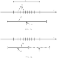
- the vertical lines 60 represent the predicted beam ranges in a target, arranged along the axis Z.
- Line 61 represents the field of view of the camera, with the arrow 62 indicating the position of the slit.
- the camera's position is such that the field of view encompasses the distance A between the two extremes of predicted beam range values (i.e. overlaps and extends on both sides of said distance A).
- the camera's field of view is smaller than the distance between the two extremes of the predicted beam ranges.
- the beam range verification cannot be done from one single camera position, and a number of camera positions can be determined for a number of groups of predicted beam ranges.
- the beam range verification of a particular beam energy is then performed for each of said groups separately. This is illustrated in figure 3b , where the dotted line illustrate a second camera position required to verify the beam range for all the spots irradiated at a particular energy.
- the measurement phase may thus be described as:
- the camera is placed at a predetermined position in between the two extremes of the predicted beam range, and the fact that the camera remains in this position while verifying the beam range at different beam energies is made possible only through the fact that the slit-shaped camera is capable of viewing through a single slit-shaped opening, an area along the beam line that is considerably larger than the width of the slit-shaped opening (see paragraph [0028] hereabove).
- This feature is not present in existing prompt gamma detection devices equipped with one or more slit-shaped collimator apertures.
- the pin-hole prompt gamma camera described in EP2140913 the camera that is applied in the apparatus of the invention has the advantage that a 1D-view of the dose distribution is obtained, which allows a more accurate and straightforward determination of the beam range.
- the above-described method includes the basic embodiment, where a single spot is irradiated by a beam with a prescribed energy.
- the energy is related to the prescribed beam range, and the camera is positioned at the location corresponding to said predicted range.
- the above described method allows to verify whether or not the actual beam range corresponds to the predicted beam range. If the difference is too great, the irradiation may be stopped, or an adjustment can be made to the beam delivery parameters (energy, position of nozzle, etc%) during the irradiation process, or in a subsequent irradiation of the target (after each spot in the complete target has been irradiated once).
- the method also comprises the step of determining from the measured profile in each spot a value of the deposited dose at the measured beam range location. This value can be derived from the number of prompt gamma detected by the camera.
- the method may then further comprise the steps of comparing said measured dose to the predicted dose, possibly followed by stopping the irradiation, or by a corrective action taken during or after the irradiation of the complete target.
- a value of the predicted dose in the precalculation phase of the method it is possible also to provide a value of the predicted number of prompt gamma detected by the camera, for instance by making a Monte Carlo simulation that takes into account the atomic structure of the target and the beam charge for that specific spot. It is then possible to directly compare the measured number of prompt gamma with the predicted number. Said comparison is equivalent to the comparison of the predicted and measured dose.
- the method comprises also the step of calculating the expected accuracy of the beam range measurement, on the basis of the beam energy and the expected dose.
- the accuracy can be quantified on the basis of a simulation of the beam and target. This provides another criterion by which the irradiation can be assessed. If the beam range is outside the expected accuracy, the irradiation may be stopped, or corrective measures may be applied during or after the irradiation of the target.
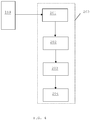
- the invention is also related to an apparatus arranged in cooperation with an irradiation installation comprising:
- the precalculation and verification modules are basically computers with the capacity for making the above described calculations and comparisons, and providing a readable output. The reduction to practice of these components is therefore not described in detail here as it is considered to be within the competence of a person skilled in the art.
- the apparatus may further be provided with an actuation module 204, configured to receive a signal representative of said difference or differences, and configured to apply on the basis of said signal, corrective measures to one or more parameters of the irradiation installation, during the irradiation of a target or after irradiation of a target.
- Said corrective measures also comprise stopping the operation of an irradiation installation.
- FIG. 5a top view
- figure 5b 3D view
- the apparatus is shown in the case where the target is positioned on a couch 10, suitable for receiving a patient but the apparatus of the invention is applicable to any type of target.
- the couch is movable by a patient positioning system (PPS) 11, known as such in the art.
- PPS patient positioning system
- the target is represented as a cube 12 with its centre coinciding with the isocenter 13 of a gantry installation.
- the gantry supports a nozzle 14 which can rotate around the target along a circular path about the horizontal gantry rotation axis 15, so that the nozzle produces a beam through the isocenter 13 from every position.
- the prompt gamma camera 100 is provided in a front wall 16 of the treatment room defined by the rotating gantry.
- the collimator 1 of the camera is provided with a slit-shaped opening 2 and a detector means 20 (scintillator, detector array) as described above.
- the camera 100 preferably has a cylindrical outer shape.
- the camera is stored in a storage location 21, in a position wherein the camera's central axis coincides with the rotation axis 15 of the gantry.
- the camera is movable with respect to the storage position by rotating it around its central axis (i.e.
- the position of the slit 2 with respect to the beam line direction 99 can be adjusted so that the slit is orthogonal to said beam line direction.
- the linear movement allows to position the camera at an optimal position with respect to the target, preferably as close as possible to the target, taking into account possible obstructions.
- the distance between the camera 100 and the target 12 is preferably measured between the iris line (see definition above) of the camera and the isocenter 13.
- the apparatus further comprises a collision avoidance system (not shown), which preferably comprises one or more sensors configured to sense the distance between the camera and any objects or persons present in the irradiation room, and a system configured to stop the camera when said distance is too small.
- a collision avoidance system (not shown), which preferably comprises one or more sensors configured to sense the distance between the camera and any objects or persons present in the irradiation room, and a system configured to stop the camera when said distance is too small.
- the camera 100 is mounted on a robotic arm 30 with six degrees of freedom.
- a robot is known as such in the art.
- the robot may be mounted in conjunction with a gantry and nozzle as described for the previous embodiment.
- the drawing only shows the gantry rotation axis 15 and the direction of the beam line 99 from a possible nozzle position.
- the robot 30 is mounted in a pit or on a pedestal 31 which can be placed in a fixed position with respect to the gantry, so that the robotic arm is free to take up any position relative to a target and a beam line, as soon as the relative position of the nozzle and the target is realised. In this case also, a collision avoidance system is recommended.
- the camera 100 is mounted on a camera guidance rail 40 which is itself mounted on the couch 10.
- the camera is movably attached to the rail 40.
- the rail is configured to position the camera at a location around the target. This allows to place the camera at the desired position with respect to the beam line 99.
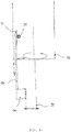
- FIG. 8a/8b / 8c A fourth embodiment is shown in figure 8a/8b / 8c .
- the camera 100 is attached to an arm 50, which is mounted on the nozzle 14 itself. Whilst remaining parallel to the beam line direction, the arm 50 is rotatable around said beam line, defined by the central axis of the nozzle 14. The camera is mounted at the end of the arm 50, with the slit 2 oriented perpendicularly to the beam line 99. The arm is movable in the direction of the beam line, and in any direction perpendicular to the beam line. In this way, the camera can be positioned at any location with respect to the target, while the slit 2 remains perpendicular to the beam line direction.
- Figures 8b / 8c show a possible mechanical apparatus for driving the movement of the arm.
- a plate 55 is arranged to be rotatable with respect to the nozzle 14, the rotation taking place around the beam line 99 of a beam produced by the nozzle.
- the plate 55 must have an opening in the middle for the passage of the beam.
- the arm 50 is slidably arranged in a block 56 which is movable in the radial direction of the plate, e.g. by rotation of a screw 57 oriented in said radial direction and engaging with the block 56.
- a rotatable gear wheel 58 is configured to engage with gear teeth 59 on the arm 50, for driving the linear movement of the arm in a direction parallel to the beam line 99.
Landscapes
- Health & Medical Sciences (AREA)
- Engineering & Computer Science (AREA)
- Biomedical Technology (AREA)
- Life Sciences & Earth Sciences (AREA)
- General Health & Medical Sciences (AREA)
- Radiology & Medical Imaging (AREA)
- Nuclear Medicine, Radiotherapy & Molecular Imaging (AREA)
- Animal Behavior & Ethology (AREA)
- Pathology (AREA)
- Public Health (AREA)
- Veterinary Medicine (AREA)
- Physics & Mathematics (AREA)
- General Physics & Mathematics (AREA)
- High Energy & Nuclear Physics (AREA)
- Molecular Biology (AREA)
- Spectroscopy & Molecular Physics (AREA)
- Radiation-Therapy Devices (AREA)
- Measurement Of Radiation (AREA)
Claims (8)
- Eine Vorrichtung zum Verifizieren des Strahlbereichs in einem von einem geladenen Hadronstrahl bestrahlten Ziel, in einer Einrichtung, die umfasst:• einen Teilchenbeschleuniger,• eine zum Abgeben eines geladenen Hadronstrahls entlang einer Strahlführung konfigurierte Düse,• ein Zielträgersystem zum Tragen eines Ziels in einer Position in Bezug auf die besagte Strahlführung,• eine prompte Gammakamera (100), die mit einer schlitzförmigen Öffnung (2) versehen ist, wobei das Sichtfeld (101) der besagten Kamera deutlich breiter ist als die Breite der schlitzförmigen Öffnung (2), damit die Kamera die Erkennung prompter Gammastrahlen ermöglicht, die nicht nur aus der Richtung mit einem Winkel von 90° bezogen auf die Strahlführung emittiert werden,wobei die besagte Vorrichtung umfasst:• ein Vorberechnungsmodul (201), das konfiguriert ist:• zum Empfangen eines Bestrahlungsplans (199), wobei der Plan folgende Daten oder Daten, die es ermöglichen, folgende Daten zu definieren, umfasst:• die Position des Ziels relativ zur Düse,• eine Mehrzahl Strahlungsenergien eines aus der vorgegebenen Düsenposition abzugebenden geladenen Hadronstrahls,• für jede Energie: den Standort einer Mehrzahl Punkte, die sich innerhalb des Ziels und in einer senkrecht zur Strahlführung verlaufenden Ebene befinden, wobei die besagte Punkte mit einem Strahl mit der definierten Energie zu bestrahlen sind;• wahlweise: die Strahlladung für jeden Punkt.• für jeden Punkt: Empfangen im Rahmen des besagten Plans oder Berechnen des vorhergesagten Strahlbereichs und vorzugsweise der am Standort des vorhergesagten Strahlbereichs abgegebenen vorhergesagten Dosis;• für jedes der besagten Energieniveaus:
Berechnen einer Position der Kamera, wobei der Schlitz orthogonal zur Strahlführung und wobei die Irislinie des Schlitzes an einem Standort in Richtung der Strahlführung zwischen und einschließlich der Endbereiche der vorhergesagten Strahlbereiche positioniert ist,• ein Positionsgebermodul (202), das zum Positionieren der Kamera in jeder besagten Position konfiguriert ist,• ein Verifizierungsmodul (203), das zum Empfangen von Strahlbereichen für jeden in den Positionen von der Kamera gemessenen Punkt konfiguriert ist, wobei das Verifizierungsmodul ferner zum Bereitstellen eines für den Unterschied zwischen den vorhergesagten und den von der Kamera gemessenen Strahlbereichen repräsentativen Ausgangs konfiguriert ist. - Vorrichtung nach Anspruch 1, wobei das Verifizierungsmodul (203) ferner zum Bereitstellen eines zweiten Ausgangs konfiguriert ist, der für den Unterschied zwischen der vorhergesagten abgegebenen Dosis und der von der in der besagten Position positionierten Kamera gemessenen Dosis repräsentativ ist.
- Vorrichtung nach Anspruch 1 oder 2, ferner umfassend ein Ansteuerungsmodul (204), das zum Empfangen eines für den besagten Unterschied bzw. die Unterschiede repräsentativen Signals konfiguriert ist, und derart konfiguriert ist, dass es während oder nach der Bestrahlung eines Ziels anhand des besagten Signals Korrekturmaßnahmen auf mindestens einen Parameter der Bestrahlungseinrichtung anwendet.
- Vorrichtung nach irgendeinem der Ansprüche 1 - 3, die zum Betrieb mit einer Bestrahlungseinrichtung geeignet ist, die ein rotierbares Gantry umfasst, wobei das besagte Positionsgebermodul (202) ein Mittel zum Rotieren der Kamera um eine Rotationsachse, die mit der Rotationsachse (15) des Gantry übereinstimmt, sowie ein Mittel zum linearen Bewegen der Kamera (100) in Richtung der besagten Rotationsachse des Gantry umfasst.
- Vorrichtung nach irgendeinem der Ansprüche 1 bis 4, wobei das besagte Positionsgebermodul (202) einen Roboterarm (30) umfasst, auf dem die Kamera montiert ist, damit die Kamera (100) mit sechs Freiheitsgraden bewegt werden kann.
- Vorrichtung nach irgendeinem der Ansprüche 1 bis 4, wobei das besagte Positionsgebermodul (202) ein Mittel zum Bewegen der Kamera (100) relativ zu einem Ziel entlang einer Bahn (40), die relativ zum besagten Ziel (12) feststeht, umfasst.
- Vorrichtung nach irgendeinem der Ansprüche 1 bis 4, wobei das Positionsgebermodul (202) einen Arm (50) umfasst, der sich parallel zur Strahlführung (99) eines von der Düse erzeugten Strahls erstreckt, wobei der besagte Arm, während er parallel zur besagten Strahlführung bleibt, derart konfiguriert ist, dass er:• die an einem äußeren Ende des Arms befestigte Kamera (100) empfangen kann,• in Richtung der Strahlführung (99) verlängerbar ist,• um die Strahlführung (99) rotierbar ist,• in eine beliebige radiale Richtung in einer senkrecht zur Strahlführung (99) verlaufenden Ebene bewegbar ist.
- Vorrichtung nach Anspruch 7, umfassend eine Platte (55), die um die Strahlführung (99) rotierbar ist, wobei der besagte Arm in einem in die radiale Richtung der Platte (55) bewegbaren Block (56) gleitend angeordnet ist.
Priority Applications (1)
| Application Number | Priority Date | Filing Date | Title |
|---|---|---|---|
| EP12729008.8A EP2707100B1 (de) | 2011-05-11 | 2012-05-11 | Vorrichtung zur teilchenstrahl-reichweitenprüfung |
Applications Claiming Priority (3)
| Application Number | Priority Date | Filing Date | Title |
|---|---|---|---|
| EP11165748 | 2011-05-11 | ||
| EP12729008.8A EP2707100B1 (de) | 2011-05-11 | 2012-05-11 | Vorrichtung zur teilchenstrahl-reichweitenprüfung |
| PCT/EP2012/058836 WO2012152938A2 (en) | 2011-05-11 | 2012-05-11 | A method and apparatus for particle beam range verification |
Publications (2)
| Publication Number | Publication Date |
|---|---|
| EP2707100A2 EP2707100A2 (de) | 2014-03-19 |
| EP2707100B1 true EP2707100B1 (de) | 2019-07-10 |
Family
ID=44786173
Family Applications (1)
| Application Number | Title | Priority Date | Filing Date |
|---|---|---|---|
| EP12729008.8A Active EP2707100B1 (de) | 2011-05-11 | 2012-05-11 | Vorrichtung zur teilchenstrahl-reichweitenprüfung |
Country Status (3)
| Country | Link |
|---|---|
| US (1) | US9358406B2 (de) |
| EP (1) | EP2707100B1 (de) |
| WO (1) | WO2012152938A2 (de) |
Families Citing this family (15)
| Publication number | Priority date | Publication date | Assignee | Title |
|---|---|---|---|---|
| NL2007596C2 (en) * | 2011-10-14 | 2013-04-16 | Univ Delft Tech | A hadron radiation installation and verification method. |
| KR101450040B1 (ko) * | 2013-06-03 | 2014-10-15 | 순천향대학교 산학협력단 | 체렌코프 효과를 이용한 감마선 감지용 프로브 및 이를 이용한 사용후핵연료 집합체의 연소도 판별 시스템 |
| EP2950119B1 (de) * | 2014-05-26 | 2016-05-18 | Ion Beam Applications S.A. | System und Verfahren zur Überprüfung eines Partikelstrahls |
| US9364688B2 (en) * | 2013-09-20 | 2016-06-14 | Ion Beam Applications, S.A. | Method and apparatus for monitoring the range of a particle beam |
| CN106267589B (zh) * | 2016-08-26 | 2019-05-21 | 东软医疗系统股份有限公司 | 一种直线加速器的控制方法及装置 |
| US11103730B2 (en) | 2017-02-23 | 2021-08-31 | Mevion Medical Systems, Inc. | Automated treatment in particle therapy |
| US11298565B2 (en) | 2017-11-16 | 2022-04-12 | Ebamed Sa | Heart arrhythmia non-invasive treatment device and method |
| US11506801B2 (en) | 2018-10-10 | 2022-11-22 | Ebamed Sa | Prompt gamma monitor for hadron therapy |
| NO346536B1 (en) * | 2019-04-10 | 2022-09-26 | Bergen Teknologioverfoering As | System for charged particle therapy verification |
| CN111973892B (zh) * | 2019-05-23 | 2022-07-08 | 千才生医股份有限公司 | 用于放射治疗的笔尖式质子束扫描系统剂量分布重建方法 |
| CN114206439B (zh) * | 2019-07-17 | 2026-04-03 | 费斯博蒂克有限公司 | 用于监视用粒子对患者身体部位的治疗的装置和方法 |
| WO2021094824A1 (en) | 2019-11-14 | 2021-05-20 | Ebamed Sa | Cardiac phase gating system for radiation therapy |
| JP7356370B2 (ja) * | 2020-02-14 | 2023-10-04 | 株式会社日立製作所 | ビーム監視システム、粒子線治療システム、およびビーム監視方法 |
| CN111208553B (zh) * | 2020-03-12 | 2024-07-12 | 中国科学院上海高等研究院 | 一种荧光靶探测器及其探测方法 |
| WO2022136925A1 (en) | 2020-12-23 | 2022-06-30 | Ebamed Sa | A multiplanar motion management system |
Citations (3)
| Publication number | Priority date | Publication date | Assignee | Title |
|---|---|---|---|---|
| EP0779081A2 (de) * | 1995-12-11 | 1997-06-18 | Hitachi, Ltd. | Strahlapparat für geladene Teilchen und Betriebsverfahren dafür |
| EP2116277A1 (de) * | 2008-05-06 | 2009-11-11 | Ion Beam Applications S.A. | Vorrichtung und Verfahren zur Überwachung und Überprüfung von Partikeltherapie |
| EP2140913A1 (de) * | 2008-07-03 | 2010-01-06 | Ion Beam Applications S.A. | Vorrichtung und Verfahren zur Partikeltherapieüberprüfung |
Family Cites Families (4)
| Publication number | Priority date | Publication date | Assignee | Title |
|---|---|---|---|---|
| US7525095B2 (en) * | 2005-05-20 | 2009-04-28 | Koninklijke Philips Electronics N.V. | Method and apparatus for human brain imaging using a nuclear medicine camera |
| WO2007126782A2 (en) * | 2006-03-28 | 2007-11-08 | Hampton University | Hadron treatment planning with adequate biological weighting |
| FR2930995B1 (fr) * | 2008-05-07 | 2010-07-30 | Centre Nat Rech Scient | Procede et dispositif de mesure en temps reel d'une dose locale lors du bombardement d'une cible par des hadrons au moyen des gamma prompts |
| WO2011143367A2 (en) * | 2010-05-11 | 2011-11-17 | Hampton University, Office Of General Counsel | Apparatus, method and system for measuring prompt gamma and other beam-induced radiation during hadron therapy treatments for dose and range verificaton purposes using ionization radiation detection |
-
2012
- 2012-05-11 US US14/116,964 patent/US9358406B2/en active Active
- 2012-05-11 EP EP12729008.8A patent/EP2707100B1/de active Active
- 2012-05-11 WO PCT/EP2012/058836 patent/WO2012152938A2/en not_active Ceased
Patent Citations (3)
| Publication number | Priority date | Publication date | Assignee | Title |
|---|---|---|---|---|
| EP0779081A2 (de) * | 1995-12-11 | 1997-06-18 | Hitachi, Ltd. | Strahlapparat für geladene Teilchen und Betriebsverfahren dafür |
| EP2116277A1 (de) * | 2008-05-06 | 2009-11-11 | Ion Beam Applications S.A. | Vorrichtung und Verfahren zur Überwachung und Überprüfung von Partikeltherapie |
| EP2140913A1 (de) * | 2008-07-03 | 2010-01-06 | Ion Beam Applications S.A. | Vorrichtung und Verfahren zur Partikeltherapieüberprüfung |
Non-Patent Citations (3)
| Title |
|---|
| MIN CHUL HEE ET AL: "Development of an Array-Type Prompt Gamma Detection System for the Online Measurement of the Range of the Proton Beam in a Patient: a Monte Carlo Feasibility Study", JOURNAL OF THE KOREAN PHYSICAL SOCIETY, SEOUL, KR, vol. 52, no. 3, 15 March 2008 (2008-03-15), pages 888 - 891, XP002509601, ISSN: 0374-4884 * |
| MIN CHUL-HEE ET AL: "Prompt gamma measurements for locating the dose falloff region in the proton therapy", APPLIED PHYSICS LETTERS, AIP, AMERICAN INSTITUTE OF PHYSICS, MELVILLE, NY, US, vol. 89, no. 18, 2 November 2006 (2006-11-02), pages 183517 - 183517, XP012086792, ISSN: 0003-6951, DOI: 10.1063/1.2378561 * |
| POLF J C ET AL: "NOTE; Measurement and calculation of characteristic prompt gamma ray spectra emitted during proton irradiation; Measurement and calculation of prompt gamma spectra", PHYSICS IN MEDICINE AND BIOLOGY, TAYLOR AND FRANCIS LTD. LONDON, GB, vol. 54, no. 22, 21 November 2009 (2009-11-21), pages N519 - N527, XP020167027, ISSN: 0031-9155 * |
Also Published As
| Publication number | Publication date |
|---|---|
| WO2012152938A3 (en) | 2013-01-10 |
| WO2012152938A2 (en) | 2012-11-15 |
| US9358406B2 (en) | 2016-06-07 |
| EP2707100A2 (de) | 2014-03-19 |
| US20140145088A1 (en) | 2014-05-29 |
Similar Documents
| Publication | Publication Date | Title |
|---|---|---|
| EP2707100B1 (de) | Vorrichtung zur teilchenstrahl-reichweitenprüfung | |
| EP2670485B1 (de) | Vorrichtung zur partikeltherapieüberprüfung | |
| Parodi et al. | In vivo range verification in particle therapy | |
| CN107041997B (zh) | 放射射束对准和放射射束测量的系统、方法和装置 | |
| CN102369457B (zh) | 探测器装置 | |
| EP2313156B1 (de) | Vorrichtung und verfahren zur partikeltherapieüberprüfung | |
| US12285633B2 (en) | Device and a method for monitoring a treatment of a body part of a patient with particles | |
| CN106604762A (zh) | 用于强度调制离子射束治疗中的快速光栅射束扫描的方法和设备 | |
| JP2010032451A (ja) | 粒子線照射システム | |
| JP2017042311A (ja) | 中性子捕捉療法システム及び中性子捕捉療法システムの制御方法 | |
| Lin et al. | A comparison of two prompt gamma imaging techniques with collimator-based cameras for range verification in proton therapy | |
| EP3169401B1 (de) | Verfahren und vorrichtung zur qualitätssicherung einer strahlentherapievorrichtung | |
| Richard | Design study of a Compton camera for prompts-gamma imaging during ion beam therapy | |
| Jeyasugiththan et al. | Measuring prompt gamma-ray emissions from elements found in tissue during passive-beam proton therapy | |
| Yoon et al. | Patient-specific quality assurance in a multileaf collimator-based CyberKnife system using the planar Ion chamber array | |
| EP4400161B1 (de) | Qualitätssicherungssystem für partikelstrahlentherapie | |
| Rinaldi | Imaging techniques in ion beam therapy: status and perspective | |
| Mohamed | Dosimetric Evaluation of High Energy Electron Beams Applied in Radiotherapy | |
| Jhala | Department of Physics and Astronomy |
Legal Events
| Date | Code | Title | Description |
|---|---|---|---|
| PUAI | Public reference made under article 153(3) epc to a published international application that has entered the european phase |
Free format text: ORIGINAL CODE: 0009012 |
|
| 17P | Request for examination filed |
Effective date: 20131112 |
|
| AK | Designated contracting states |
Kind code of ref document: A2 Designated state(s): AL AT BE BG CH CY CZ DE DK EE ES FI FR GB GR HR HU IE IS IT LI LT LU LV MC MK MT NL NO PL PT RO RS SE SI SK SM TR |
|
| DAX | Request for extension of the european patent (deleted) | ||
| GRAP | Despatch of communication of intention to grant a patent |
Free format text: ORIGINAL CODE: EPIDOSNIGR1 |
|
| STAA | Information on the status of an ep patent application or granted ep patent |
Free format text: STATUS: GRANT OF PATENT IS INTENDED |
|
| INTG | Intention to grant announced |
Effective date: 20181210 |
|
| GRAS | Grant fee paid |
Free format text: ORIGINAL CODE: EPIDOSNIGR3 |
|
| GRAA | (expected) grant |
Free format text: ORIGINAL CODE: 0009210 |
|
| STAA | Information on the status of an ep patent application or granted ep patent |
Free format text: STATUS: THE PATENT HAS BEEN GRANTED |
|
| AK | Designated contracting states |
Kind code of ref document: B1 Designated state(s): AL AT BE BG CH CY CZ DE DK EE ES FI FR GB GR HR HU IE IS IT LI LT LU LV MC MK MT NL NO PL PT RO RS SE SI SK SM TR |
|
| REG | Reference to a national code |
Ref country code: GB Ref legal event code: FG4D |
|
| REG | Reference to a national code |
Ref country code: CH Ref legal event code: EP Ref country code: AT Ref legal event code: REF Ref document number: 1152889 Country of ref document: AT Kind code of ref document: T Effective date: 20190715 |
|
| REG | Reference to a national code |
Ref country code: DE Ref legal event code: R096 Ref document number: 602012061887 Country of ref document: DE |
|
| REG | Reference to a national code |
Ref country code: IE Ref legal event code: FG4D |
|
| REG | Reference to a national code |
Ref country code: NL Ref legal event code: FP |
|
| REG | Reference to a national code |
Ref country code: LT Ref legal event code: MG4D |
|
| REG | Reference to a national code |
Ref country code: AT Ref legal event code: MK05 Ref document number: 1152889 Country of ref document: AT Kind code of ref document: T Effective date: 20190710 |
|
| PG25 | Lapsed in a contracting state [announced via postgrant information from national office to epo] |
Ref country code: BG Free format text: LAPSE BECAUSE OF FAILURE TO SUBMIT A TRANSLATION OF THE DESCRIPTION OR TO PAY THE FEE WITHIN THE PRESCRIBED TIME-LIMIT Effective date: 20191010 Ref country code: SE Free format text: LAPSE BECAUSE OF FAILURE TO SUBMIT A TRANSLATION OF THE DESCRIPTION OR TO PAY THE FEE WITHIN THE PRESCRIBED TIME-LIMIT Effective date: 20190710 Ref country code: PT Free format text: LAPSE BECAUSE OF FAILURE TO SUBMIT A TRANSLATION OF THE DESCRIPTION OR TO PAY THE FEE WITHIN THE PRESCRIBED TIME-LIMIT Effective date: 20191111 Ref country code: HR Free format text: LAPSE BECAUSE OF FAILURE TO SUBMIT A TRANSLATION OF THE DESCRIPTION OR TO PAY THE FEE WITHIN THE PRESCRIBED TIME-LIMIT Effective date: 20190710 Ref country code: LT Free format text: LAPSE BECAUSE OF FAILURE TO SUBMIT A TRANSLATION OF THE DESCRIPTION OR TO PAY THE FEE WITHIN THE PRESCRIBED TIME-LIMIT Effective date: 20190710 Ref country code: FI Free format text: LAPSE BECAUSE OF FAILURE TO SUBMIT A TRANSLATION OF THE DESCRIPTION OR TO PAY THE FEE WITHIN THE PRESCRIBED TIME-LIMIT Effective date: 20190710 Ref country code: AT Free format text: LAPSE BECAUSE OF FAILURE TO SUBMIT A TRANSLATION OF THE DESCRIPTION OR TO PAY THE FEE WITHIN THE PRESCRIBED TIME-LIMIT Effective date: 20190710 Ref country code: NO Free format text: LAPSE BECAUSE OF FAILURE TO SUBMIT A TRANSLATION OF THE DESCRIPTION OR TO PAY THE FEE WITHIN THE PRESCRIBED TIME-LIMIT Effective date: 20191010 |
|
| PG25 | Lapsed in a contracting state [announced via postgrant information from national office to epo] |
Ref country code: AL Free format text: LAPSE BECAUSE OF FAILURE TO SUBMIT A TRANSLATION OF THE DESCRIPTION OR TO PAY THE FEE WITHIN THE PRESCRIBED TIME-LIMIT Effective date: 20190710 Ref country code: ES Free format text: LAPSE BECAUSE OF FAILURE TO SUBMIT A TRANSLATION OF THE DESCRIPTION OR TO PAY THE FEE WITHIN THE PRESCRIBED TIME-LIMIT Effective date: 20190710 Ref country code: GR Free format text: LAPSE BECAUSE OF FAILURE TO SUBMIT A TRANSLATION OF THE DESCRIPTION OR TO PAY THE FEE WITHIN THE PRESCRIBED TIME-LIMIT Effective date: 20191011 Ref country code: IS Free format text: LAPSE BECAUSE OF FAILURE TO SUBMIT A TRANSLATION OF THE DESCRIPTION OR TO PAY THE FEE WITHIN THE PRESCRIBED TIME-LIMIT Effective date: 20191110 Ref country code: LV Free format text: LAPSE BECAUSE OF FAILURE TO SUBMIT A TRANSLATION OF THE DESCRIPTION OR TO PAY THE FEE WITHIN THE PRESCRIBED TIME-LIMIT Effective date: 20190710 Ref country code: RS Free format text: LAPSE BECAUSE OF FAILURE TO SUBMIT A TRANSLATION OF THE DESCRIPTION OR TO PAY THE FEE WITHIN THE PRESCRIBED TIME-LIMIT Effective date: 20190710 |
|
| PG25 | Lapsed in a contracting state [announced via postgrant information from national office to epo] |
Ref country code: TR Free format text: LAPSE BECAUSE OF FAILURE TO SUBMIT A TRANSLATION OF THE DESCRIPTION OR TO PAY THE FEE WITHIN THE PRESCRIBED TIME-LIMIT Effective date: 20190710 |
|
| PG25 | Lapsed in a contracting state [announced via postgrant information from national office to epo] |
Ref country code: RO Free format text: LAPSE BECAUSE OF FAILURE TO SUBMIT A TRANSLATION OF THE DESCRIPTION OR TO PAY THE FEE WITHIN THE PRESCRIBED TIME-LIMIT Effective date: 20190710 Ref country code: IT Free format text: LAPSE BECAUSE OF FAILURE TO SUBMIT A TRANSLATION OF THE DESCRIPTION OR TO PAY THE FEE WITHIN THE PRESCRIBED TIME-LIMIT Effective date: 20190710 Ref country code: PL Free format text: LAPSE BECAUSE OF FAILURE TO SUBMIT A TRANSLATION OF THE DESCRIPTION OR TO PAY THE FEE WITHIN THE PRESCRIBED TIME-LIMIT Effective date: 20190710 Ref country code: EE Free format text: LAPSE BECAUSE OF FAILURE TO SUBMIT A TRANSLATION OF THE DESCRIPTION OR TO PAY THE FEE WITHIN THE PRESCRIBED TIME-LIMIT Effective date: 20190710 Ref country code: DK Free format text: LAPSE BECAUSE OF FAILURE TO SUBMIT A TRANSLATION OF THE DESCRIPTION OR TO PAY THE FEE WITHIN THE PRESCRIBED TIME-LIMIT Effective date: 20190710 |
|
| PG25 | Lapsed in a contracting state [announced via postgrant information from national office to epo] |
Ref country code: IS Free format text: LAPSE BECAUSE OF FAILURE TO SUBMIT A TRANSLATION OF THE DESCRIPTION OR TO PAY THE FEE WITHIN THE PRESCRIBED TIME-LIMIT Effective date: 20200224 Ref country code: SK Free format text: LAPSE BECAUSE OF FAILURE TO SUBMIT A TRANSLATION OF THE DESCRIPTION OR TO PAY THE FEE WITHIN THE PRESCRIBED TIME-LIMIT Effective date: 20190710 Ref country code: SM Free format text: LAPSE BECAUSE OF FAILURE TO SUBMIT A TRANSLATION OF THE DESCRIPTION OR TO PAY THE FEE WITHIN THE PRESCRIBED TIME-LIMIT Effective date: 20190710 Ref country code: CZ Free format text: LAPSE BECAUSE OF FAILURE TO SUBMIT A TRANSLATION OF THE DESCRIPTION OR TO PAY THE FEE WITHIN THE PRESCRIBED TIME-LIMIT Effective date: 20190710 |
|
| REG | Reference to a national code |
Ref country code: DE Ref legal event code: R097 Ref document number: 602012061887 Country of ref document: DE |
|
| PLBE | No opposition filed within time limit |
Free format text: ORIGINAL CODE: 0009261 |
|
| STAA | Information on the status of an ep patent application or granted ep patent |
Free format text: STATUS: NO OPPOSITION FILED WITHIN TIME LIMIT |
|
| PG2D | Information on lapse in contracting state deleted |
Ref country code: IS |
|
| 26N | No opposition filed |
Effective date: 20200603 |
|
| PG25 | Lapsed in a contracting state [announced via postgrant information from national office to epo] |
Ref country code: SI Free format text: LAPSE BECAUSE OF FAILURE TO SUBMIT A TRANSLATION OF THE DESCRIPTION OR TO PAY THE FEE WITHIN THE PRESCRIBED TIME-LIMIT Effective date: 20190710 |
|
| PG25 | Lapsed in a contracting state [announced via postgrant information from national office to epo] |
Ref country code: MC Free format text: LAPSE BECAUSE OF FAILURE TO SUBMIT A TRANSLATION OF THE DESCRIPTION OR TO PAY THE FEE WITHIN THE PRESCRIBED TIME-LIMIT Effective date: 20190710 Ref country code: LI Free format text: LAPSE BECAUSE OF NON-PAYMENT OF DUE FEES Effective date: 20200531 Ref country code: CH Free format text: LAPSE BECAUSE OF NON-PAYMENT OF DUE FEES Effective date: 20200531 |
|
| PG25 | Lapsed in a contracting state [announced via postgrant information from national office to epo] |
Ref country code: LU Free format text: LAPSE BECAUSE OF NON-PAYMENT OF DUE FEES Effective date: 20200511 |
|
| PG25 | Lapsed in a contracting state [announced via postgrant information from national office to epo] |
Ref country code: IE Free format text: LAPSE BECAUSE OF NON-PAYMENT OF DUE FEES Effective date: 20200511 |
|
| PG25 | Lapsed in a contracting state [announced via postgrant information from national office to epo] |
Ref country code: MT Free format text: LAPSE BECAUSE OF FAILURE TO SUBMIT A TRANSLATION OF THE DESCRIPTION OR TO PAY THE FEE WITHIN THE PRESCRIBED TIME-LIMIT Effective date: 20190710 Ref country code: CY Free format text: LAPSE BECAUSE OF FAILURE TO SUBMIT A TRANSLATION OF THE DESCRIPTION OR TO PAY THE FEE WITHIN THE PRESCRIBED TIME-LIMIT Effective date: 20190710 |
|
| PG25 | Lapsed in a contracting state [announced via postgrant information from national office to epo] |
Ref country code: MK Free format text: LAPSE BECAUSE OF FAILURE TO SUBMIT A TRANSLATION OF THE DESCRIPTION OR TO PAY THE FEE WITHIN THE PRESCRIBED TIME-LIMIT Effective date: 20190710 |
|
| PGFP | Annual fee paid to national office [announced via postgrant information from national office to epo] |
Ref country code: NL Payment date: 20250526 Year of fee payment: 14 |
|
| PGFP | Annual fee paid to national office [announced via postgrant information from national office to epo] |
Ref country code: DE Payment date: 20250529 Year of fee payment: 14 |
|
| PGFP | Annual fee paid to national office [announced via postgrant information from national office to epo] |
Ref country code: GB Payment date: 20250527 Year of fee payment: 14 |
|
| PGFP | Annual fee paid to national office [announced via postgrant information from national office to epo] |
Ref country code: BE Payment date: 20250527 Year of fee payment: 14 |
|
| PGFP | Annual fee paid to national office [announced via postgrant information from national office to epo] |
Ref country code: FR Payment date: 20250526 Year of fee payment: 14 |