EP2707110B1 - Skibindung zur befestigung eines skitourenstiefels auf einem rennski oder dergleichen - Google Patents
Skibindung zur befestigung eines skitourenstiefels auf einem rennski oder dergleichen Download PDFInfo
- Publication number
- EP2707110B1 EP2707110B1 EP12729213.4A EP12729213A EP2707110B1 EP 2707110 B1 EP2707110 B1 EP 2707110B1 EP 12729213 A EP12729213 A EP 12729213A EP 2707110 B1 EP2707110 B1 EP 2707110B1
- Authority
- EP
- European Patent Office
- Prior art keywords
- turret
- ski
- structured
- latch element
- strut
- Prior art date
- Legal status (The legal status is an assumption and is not a legal conclusion. Google has not performed a legal analysis and makes no representation as to the accuracy of the status listed.)
- Not-in-force
Links
Images


Classifications
-
- A—HUMAN NECESSITIES
- A63—SPORTS; GAMES; AMUSEMENTS
- A63C—SKATES; SKIS; ROLLER SKATES; DESIGN OR LAYOUT OF COURTS, RINKS OR THE LIKE
- A63C9/00—Ski bindings
- A63C9/08—Ski bindings yieldable or self-releasing in the event of an accident, i.e. safety bindings
- A63C9/084—Ski bindings yieldable or self-releasing in the event of an accident, i.e. safety bindings with heel hold-downs, e.g. swingable
- A63C9/0847—Details of the manual release
-
- A—HUMAN NECESSITIES
- A63—SPORTS; GAMES; AMUSEMENTS
- A63C—SKATES; SKIS; ROLLER SKATES; DESIGN OR LAYOUT OF COURTS, RINKS OR THE LIKE
- A63C9/00—Ski bindings
- A63C9/006—Ski bindings with a climbing wedge
-
- A—HUMAN NECESSITIES
- A63—SPORTS; GAMES; AMUSEMENTS
- A63C—SKATES; SKIS; ROLLER SKATES; DESIGN OR LAYOUT OF COURTS, RINKS OR THE LIKE
- A63C9/00—Ski bindings
- A63C9/08—Ski bindings yieldable or self-releasing in the event of an accident, i.e. safety bindings
- A63C9/0807—Ski bindings yieldable or self-releasing in the event of an accident, i.e. safety bindings for both towing and downhill skiing
-
- A—HUMAN NECESSITIES
- A63—SPORTS; GAMES; AMUSEMENTS
- A63C—SKATES; SKIS; ROLLER SKATES; DESIGN OR LAYOUT OF COURTS, RINKS OR THE LIKE
- A63C9/00—Ski bindings
- A63C9/08—Ski bindings yieldable or self-releasing in the event of an accident, i.e. safety bindings
- A63C9/084—Ski bindings yieldable or self-releasing in the event of an accident, i.e. safety bindings with heel hold-downs, e.g. swingable
- A63C9/0845—Ski bindings yieldable or self-releasing in the event of an accident, i.e. safety bindings with heel hold-downs, e.g. swingable the body or base or a jaw pivoting about a vertical axis, i.e. side release
-
- A—HUMAN NECESSITIES
- A63—SPORTS; GAMES; AMUSEMENTS
- A63C—SKATES; SKIS; ROLLER SKATES; DESIGN OR LAYOUT OF COURTS, RINKS OR THE LIKE
- A63C9/00—Ski bindings
- A63C9/08—Ski bindings yieldable or self-releasing in the event of an accident, i.e. safety bindings
- A63C9/085—Ski bindings yieldable or self-releasing in the event of an accident, i.e. safety bindings with sole hold-downs, e.g. swingable
- A63C9/08507—Ski bindings yieldable or self-releasing in the event of an accident, i.e. safety bindings with sole hold-downs, e.g. swingable with a plurality of mobile jaws
- A63C9/08528—Ski bindings yieldable or self-releasing in the event of an accident, i.e. safety bindings with sole hold-downs, e.g. swingable with a plurality of mobile jaws pivoting about a longitudinal axis
-
- A—HUMAN NECESSITIES
- A63—SPORTS; GAMES; AMUSEMENTS
- A63C—SKATES; SKIS; ROLLER SKATES; DESIGN OR LAYOUT OF COURTS, RINKS OR THE LIKE
- A63C9/00—Ski bindings
- A63C9/08—Ski bindings yieldable or self-releasing in the event of an accident, i.e. safety bindings
- A63C9/086—Ski bindings yieldable or self-releasing in the event of an accident, i.e. safety bindings using parts which are fixed on the shoe of the user and are releasable from the ski binding
Definitions
- the present invention relates to a ski binding device for fastening a ski mountaineering boot on a downhill ski or the like.
- the most common ski mountaineering boots substantially consist of a shell made of rigid plastic material which is shaped so as to accommodate the user's foot, and is provided on the bottom with a front sole and a rear heel, usually provided with a lugged profile and made of a non-slip elastomeric material; with a cuff made of a rigid plastic material, which is C-shaped so as to envelop the user's ankle from behind, and is hinged to the upper part of the shell so as to oscillate about a transversal reference axis substantially coinciding with the articulation axis of the ankle; with an inner shoe made of soft, heat-insulating material, which is removably inserted into the shell and the cuff, and is shaped so as to envelop and protect both the foot and the lower part of the user's leg; and with a series of manually-operated closing hooks, which are appropriately distributed on the shell and on the cuff, and are structured so as to tighten the shell and the cuff in
- the shell of the ski mountaineering boots is provided on the front with a small, substantially duck-billed projecting appendix, which protrudes from the nose-shaped tip of the shell remaining locally substantially coplanar with the front sole, and is structured so as to be coupled in a rigid, stable, although easily releasable manner, with the toepiece of the ski mountaineering binding device which, in turn, is rigidly fixed onto the central part of the downhill ski.
- the ski mountaineering binding device instead consists of a toepiece and a heelpiece, which are rigidly and stably fixed to the back of the downhill ski, at a predetermined distance from each other, and are structured so as to alternatively and as desired:
- the rotation axis of the ski boot is perpendicular to the rotation axis of the downhill ski, i.e. is oriented so as to be locally substantially perpendicular both to the middle plane of the ski and to the middle plane of the ski boot.
- the toepiece is usually provided with a gripper-like clamping member, which is structured so as to clamp and stably retain the projecting duck-billed appendix of the shell, while allowing the shell to freely oscillate/pivot with respect to the ski underneath about the rotation axis of the boot.
- the heelpiece of the binding device instead, is structured so as to selectively hook and lock the rear part of the shell, so as to selectively prevent the boot from rotating by pivoting on the toepiece and moving the heel away from the back of the ski.
- a binding device is made for fastening a ski mountaineering boot to a downhill ski or the like, as set forth in claim 1 and preferably, but not necessarily, in any one of the dependent claims.
- numeral 1 indicates as a whole a ski mountaineering binding device specifically structured to fasten a ski mountaineering or Telemark ski boot 2 onto the central segment of a downhill ski 3, ski mountaineering ski or the like, of the known type, in a stable, although easily releasable manner.
- the binding device 1 is structured to fasten a ski mountaineering or Telemark ski boot 2 of known type onto the central segment of a downhill ski 3 or the like, which ski boot is provided with a rigid lower shell 4 made of plastic and/or composite material, which is shaped so as to accommodate the user's foot, and is further provided on the bottom with a front sole 5 and a rear heel 6, which preferably, but not necessarily have a lugged profile and are preferably, but not necessarily, made of a non-slip elastomeric material.
- the shell 4 is also provided in the front with a small, substantially duck-billed appendix 7, which protrudes from the nose-shaped tip of the shell 4 while remaining locally substantially coplanar to the front sole 5, and is structured so as to be coupled/hooked to the binding device 1 which, in turn, is rigidly fixed to the central segment of the downhill ski 3.
- the ski boot 2 in addition to the shell 4, also comprises a rigid cuff 8 made of a plastic and/or composite material, which is substantially C-shaped so as to envelop the user's ankle from behind, and is hinged onto the upper part of the shell 4 so as to freely oscillate about a transversal reference axis, which is substantially perpendicular to the middle plane of the ski boot (i.e.
- an inner shoe made of a soft, heat-insulating material, which is removably inserted into shell 4 and cuff 8, and is shaped so as to envelop and protect both the foot and the lower part of the user's leg; and a series of manually-operated closing hooks, which are positioned on the shell 4 and on the cuff 8, and are structured so as to tighten the shell 4 and the cuff 8 so as to immobilize the user's leg in the shoe 8.
- shell 4 is finally, preferably but not necessarily, provided with a transversal stiffening bar (not shown) made of a metal material, which extends into the projecting duck-billed appendix 7 while remaining locally substantially perpendicular to the middle plane of the ski boot, and has its two axial ends which emerge/surface from the outside of the projecting appendix 7 at the two side edges of the same appendix.
- a transversal stiffening bar (not shown) made of a metal material, which extends into the projecting duck-billed appendix 7 while remaining locally substantially perpendicular to the middle plane of the ski boot, and has its two axial ends which emerge/surface from the outside of the projecting appendix 7 at the two side edges of the same appendix.
- the ski mountaineering binding device 1 instead consists of a toepiece 10 and a heelpiece 11 which are rigidly fixed onto the back of the central segment of the downhill ski 3, aligned along the longitudinal axis L of ski 3, at a predetermined distance from each other, and are structured so as to selectively clamp/hook and retain the front part and the rear part of shell 4, respectively.
- the toepiece 10 and the heelpiece 11 of the ski mountaineering binding device 1 are structured so as to selectively and as desired:
- toepiece 10 is provided with a gripper-like clamping member 12 or the like which is structured so as to selectively clamp and retain only the front part of the shell 4, while allowing the front part of the shell 4 to freely oscillate/pivot on the toepiece 10 about the rotation axis A of the ski boot.
- Heelpiece 11 is instead structured so as to selectively hook and lock/retain the rear part of the shell 4 roughly at the heel, so as to stably retain the heel 6 of the ski boot 2 in abutment on, or however close to, the back of the ski 3, and therefore prevent any rotation of the ski boot 2 on the toepiece 10 about the rotation axis A of the ski boot.
- the clamping member 12 of the toepiece 10 is structured so as to tighten the side edges of the projecting appendix 7 of the shell, thus being in abutment on the projecting appendix 7 at the two axial ends of the transversal stiffening bar possibly embedded in the appendix itself, while allowing the projecting appendix 7 of the shell to freely oscillate/pivot with respect to the toepiece 10 at the contact points between the gripper-like clamping member 12 and the side edges of the projecting appendix 7.
- the rotation axis A of the ski boot is positioned on the projecting appendix 7 of shell 4, at the contact points between the gripper-like clamping member 12 and the side edges of the projecting appendix 7. Furthermore, when the front part of shell 4 is fixed onto the toepiece 10 by means of the clamping member 12, the longitudinal axis of the transversal stiffening bar of the projecting appendix 7, if present, coincides with the rotation axis of the ski boot 2.
- the toepiece 10 of the ski mountaineering binding device 1 is a component widely known in the field and will not be further described.
- the heelpiece 11 of the ski mountaineering binding device 1 comprises instead a fastening plate or base 13 which is structured so as to be rigidly fastened to the back of the downhill ski 3 or the like; and a turret 14 which protrudes upwards from the upper face of the fastening plate 13, parallel to a reference axis B which is preferably, but not necessarily, locally substantially perpendicular to the laying plane of the fastening plate 13, i.e. is locally substantially perpendicular to the back of the ski 3 itself and to the longitudinal ski axis L.
- heelpiece 11 comprises a hooking projecting appendix 15 which juts out from the turret 14 towards the toepiece 10, and is structured so as to hook/couple to the rear part of the shell 4 roughly at the heel, so as to stably retain the heel 6 of the ski boot 2 in abutment on, or however close to, the back of the ski 3, thus preventing any rotation of the ski boot 2 on the toepiece 10 about the rotation axis A of the boot.
- the hooking projecting appendix 15 juts out from the turret 14 remaining locally substantially parallel to a reference axis C which is preferably arranged locally substantially parallel to, or however aligned with, the longitudinal axis L of ski 3, and is shaped/structured so as to reach and engage the rear part of the shell 4 to stably retain the heel 6 of the ski boot 2 in abutment on, or however close to, the back of ski 3, when axis C is parallel to, or however substantially aligned with, the longitudinal ski axis L.
- a reference axis C which is preferably arranged locally substantially parallel to, or however aligned with, the longitudinal axis L of ski 3, and is shaped/structured so as to reach and engage the rear part of the shell 4 to stably retain the heel 6 of the ski boot 2 in abutment on, or however close to, the back of ski 3, when axis C is parallel to, or however substantially aligned with, the longitudinal ski axis L.
- the heelpiece 11 is positioned on the central segment of the downhill ski 3 or the like at a predetermined nominal distance from the clamping member 12 of the toepiece 10, so as to allow the projecting appendix 15 to reach and stably hook/lock the rear part of the shell 4, when the clamping member 12 of the toepiece 10 is tightened/closed on the projecting appendix 7 of shell 4 and allows the ski boot 2 to rotate on the toepiece 10 about axis A.
- toepiece 10 and heelpiece 11 obviously depends on the dimensions/length of the shell 4, i.e. on the size of the ski boot 2.
- the turret 14 is preferably fixed onto the fastening plate 13 with the possibility of freely rotating about axis B, and the heelpiece 13 is preferably also provided with an elastic programmed-release locking member 16, which is structured so as to allow the rotation of turret 14 about axis B when the twisting torque exceeds a predetermined threshold value.
- the elastic locking member 16 is structured so as to elastically contrast any rotation of turret 14 about axis B, which would compromise the alignment between reference axis C of the hooking appendix 15 and the longitudinal ski axis L, such an alignment allowing the projecting appendix 15 to engage the rear part of shell 4 so as to stably retain the heel 6 of the ski boot 2 in abutment on, or however close to, the back of ski 3, thus preventing any rotation of the ski boot 2 about axis A.
- the upper turret 14 is partially inserted and locked in an axially rotational manner within a tubular cylindrical hub 16 which juts out from the upper face of the fastening plate 13, thus remaining locally coaxial to the rotation axis B of the turret 14.
- the elastic locking member 16 is preferably, but not necessarily accommodated in the portion of turret 14 which is rotationally inserted into the hub 17, and comprises:
- the helical spring 18 is fitted in the through hole 19 so that one of its two ends abuts on the locking ball 20 and the other is on the threaded dowel 21, and is preloaded under compression by means of the threaded dowel 21, so as to push and strongly maintain the locking ball 20 abutting on the inner surface of the hub 17, within a stop seat or recess 20a appropriately obtained on the cylindrical tubular wall of hub 17.
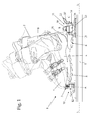
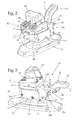
- the hooking projecting appendix 15 of the heelpiece 11 is fixed instead onto the turret 14 with the possibility of moving with respect to the turret 14 between a completely extracted position (see figures 1 , 2 and 4 ), in which the hooking projecting appendix 15 juts out from the body of the turret 14 by a predetermined length l 1 sufficient to completely engage the rear part of the shell 4 so as to prevent any rotation of the ski boot 2 about axis A; and a retracted position (see figures 3 and 5 ), in which the hooking projecting appendix 15 is completely retracted within the body of the turret 14, or juts out from the body of the turret 14 by a length l 2 which is considerably lower than length l 1 , so as to not reach and lock the rear part of shell 4.
- the heelpiece 11 also comprises a manually-operated command device 22, which is structured so as to selectively and alternatively move and lock the hooking projecting appendix 15 either in the completely extracted position or in the retracted position.
- the command device 22 can arrange the hooking projecting appendix 15 alternatively and as desired either in the completely extracted position or in the retracted position, by moving the projecting appendix 15 with respect to the turret 14 in a direction d locally parallel to reference axis C of the protruding appendix itself.
- the heelpiece 11 comprises a latch element 23 which extends in a pass-through manner through the body of turret 14, thus remaining locally substantially coaxial, or however parallel, to the reference axis C of the projecting appendix 15, with the possibility of moving forwards and backwards with respect to the turret 14 parallel to axis C.
- the hooking projecting appendix 15 consists of the tip of the latch element 23, and the command device 22 is structured so as to move the latch element 23 forward and backward on the turret 14 parallel to axis C, and then to stably lock the latch element 23 alternatively in two different working positions.
- the command device 22 is structured so as to move and lock the latch element 23 to an advanced position (see figure 4 ), in which the tip 15 of the latch element 23 juts out from the body of the turret 14 by a predetermined length l 1 sufficient to completely engage the rear part of the shell 4 so as to prevent any rotation of the ski boot 2 about axis A; or to a retracted position (see figure 6 ) in which the tip 15 of the latch element 23 is either completely retracted within the body of turret 14, or juts out from the body of turret 14 by a length l 2 which is considerably shorter than the length l 1 , so as not to reach and lock the rear part of shell 4.
- the hooking projecting appendix 15 is in the completely extracted position when the latch element 23 is in the advanced position.
- the command device 22 comprises:
- the manually-operated moving member 25 is also structured so as to selectively lock the latch element 23 in the retracted position, thus overcoming the elastic force of the antagonist elastic element 24.
- the latch element 23 consists of a sliding shoe or carriage 26, which is inserted in an axially sliding manner into an elongated cavity 26a extending into the body of turret 14, thus remaining locally coaxial to the reference axis C of the projecting appendix 15; of a pair of rectilinear stems or pins 27 preferably, but not necessarily, with circular section, extending side by side and parallel to axis C, on opposite sides of the middle plane of turret 14, so as to completely cross the sliding shoe or carriage 26 and jut out from both sides of turret 14; and of a crosspiece 28 which is adapted to rigidly connect together the rear distal ends of the two pins 27, i.e. the ends which are on the opposite side with respect to tip 10.
- the two rectilinear pins 27 are rigidly fixed to the sliding shoe or carriage 26 so as to move parallel to axis C, along with the sliding shoe or carriage 26; while, the front distal ends of the two rectilinear pins 27, i.e. the distal ends which face the tip 10 of the ski mountaineer binding device 1, are shaped/structured so as to be engaged in the rear part of shell 4 in order to stably retain the heel 6 of the ski boot 2 in abutment on, or however close to, the back of ski 3.
- the front distal ends of the two rectilinear pins 27 can axially move from and to the tip 10 in order to couple and lock the rear part of the shell 4 hinged on the gripper-like clamping member 12 of the toepiece 10, thus forming the hooking projecting appendix 15 of the heelpiece 11.
- the elongated cavity 26a which is obtained within turret 14 is obviously shaped/dimensioned so as to allow the sliding shoe or carriage 26 to move within turret 14 parallel to axis C, between an advanced position (see figure 4 ), in which the distal ends 15 of the two rectilinear pins 27 jut out from the body of turret 14 by a predetermined length l 1 sufficient to completely engage the rear part of shell 4 so as to prevent any rotation of the ski boot 2 about the axis A; and a retracted position (see figure 5 ), in which the distal ends 15 of the two rectilinear pins 27 are either completely retracted within the body of turret 14, or jut out from the body of turret 14 by a length l 2 which is much shorter than the length l 1 , so as not to reach the rear part of shell 4.
- the antagonist elastic element 24 instead preferably, but not necessarily, consists of a helical spring 24 or similar elastic member, extending into the elongated cavity 26a, locally substantially coaxial to axis C, so as to be arranged between the two rectilinear pins 27, and one of its two axial ends is stably in abutment on a body of the sliding shoe 26 and the other is on the body of turret 14.
- the helical spring 24 is additionally preloaded under compression so as to strongly push and maintain the sliding shoe or carriage 26 in abutment on the end of the elongated cavity 26a facing the toepiece 10, so as to make the distal front ends 15 of the two rectilinear pins 27 protrude and maintain them either in the advanced or in the completely retracted position.
- the manually-operated moving member 25 which allows the user to move the latch element 23 forwards and backwards thus overcoming the force of the helical spring 24, comprises instead:
- the locking device 30 is structured so as to allow the command lever 29 to oscillate about axis D to be alternatively arranged in a locking position (see figures 2 and 4 ) in which the command lever 29 is arranged in a substantially vertical position, so as to allow the antagonist elastic element 24 to arrange the latch element 23 in the advanced position; in an unlocking position (see figures 3 and 5 ) in which the command lever 29 is tilted by a predetermined angle with respect to the vertical, so as to arrange and maintain the latch element 23 in the retracted position, thus overcoming the force of the helical spring 24; and finally in a switching position, in which the command lever 29 is tilted by a predetermined angle larger than that taken in the unlocking position.
- the locking device 30 is further structured so as to allow the command lever 29 to move/pass from the unlocking position to the locking position, exclusively after the command lever 29 has been temporarily positioned in the switching position.
- the command lever 29 engages in a pass-through manner the recess delimited by the two rectilinear pins 27 and by the stiffening crosspiece 28 of the latch element 23, so as to rest, and freely slide, on the stiffening crosspiece 28 of the latch element 23.
- the locking device 30 comprises instead a rigid longitudinal stem or strut 31, which has a first end hinged in a freely rotational and sliding manner within a transversal guide slot 29a made on the body of the command lever 29, and a second end inserted in an axially sliding manner into the body of turret 14, immediately underneath the latch element 23; and a flip-flop snap locking mechanism 32 which is accommodated within turret 14, immediately under the latch element 23, and is structured so as to selectively prevent the second end of the first rigid strut 31 from penetrating into the body of turret 14 beyond a predetermined limit which corresponds to arranging the command lever 29 in the above-mentioned unlocking position.
- the snap locking mechanism 32 is structured so as to allow the longitudinal strut 31 to slide into turret 14 between an advanced position, which corresponds to the command lever 29 arranged in the locking position, and a retracted position which corresponds to the command lever 29 arranged in the switching position; and is furthermore structured so as to selectively stop/lock the stroke of the strut 31 towards the advanced position, when the strut 31 is in an intermediate position between the advanced position and the retracted position.
- the command lever 29 is in the unlocking position when the strut 31 is in the intermediate position and the snap locking mechanism 32 is finally structured so as to be arranged in/switch to the configuration which leaves the strut 31 free to complete the stroke towards the advanced position, when the longitudinal strut 31 is temporarily taken to the retracted position.
- the portion of strut 31, which is slidingly inserted in turret 14, extends along a reference axis E which is locally substantially coplanar and preferably also substantially parallel to axis C of the latch element 23.
- the longitudinal strut 31 preferably, but not necessarily, consists of a fork element 31 which has a central trunk hinged directly onto the command lever 29 by means of a transversal pin which may freely slide within the guide slot 29a made on the body of the command lever 29, and has the two arms or tines 31a which extend in an axially sliding manner into turret 14, where the snap locking mechanism 32 is accommodated.
- the snap locking mechanism 32 preferably comprises instead a pivoting rocker arm 33 which is fixed within turret 14, next to the second end of the rigid strut 31, with the possibility of freely oscillating while remaining on a laying plane locally and substantially coplanar to the longitudinal axis E of the rigid strut 31; and an elastic member 34, here a scissor-like spring, which is interposed between the pivoting rocker arm 33 and the turret 14, and is structured so as to elastically maintain the rigid strut 31, either selectively or alternatively in two different operating positions.
- an elastic member 34 here a scissor-like spring
- the pivoting rocker arm 33 In the first operating position, the pivoting rocker arm 33 is close to the rigid strut 31, and can hook the rigid strut 31 thus preventing it from completing the movement from the intermediate position to the advanced position, i.e. from penetrating further into the body of turret 14. In the second operating position, the pivoting rocker arm 33 is instead away from the rigid strut 31, and allows the rigid strut 31 to move freely with respect to turret 14, parallel to axis E and towards the advanced position.
- the pivoting rocker arm 33 is preferably hinged onto the turret 14 so as to freely oscillate about a transversal rotation axis F which is locally substantially orthogonal to reference axis E of the rigid strut 31, while remaining on a laying plane locally substantially coplanar or however parallel to axes B and E, and preferably also substantially coinciding with the middle plane P of turret 14.
- the pivoting rocker arm 33 is structured/shaped so as to automatically cause the movement of the rocker arm from the second to the first operative position, when the longitudinal strut 31 reaches the advanced position under the force of the elastic element 24, and so as to automatically cause the movement of the rocker arm from the first to the second operative position, when the longitudinal strut 31 reaches the retracted position being pulled by the command lever 29.
- the pivoting rocker arm 33 is preferably positioned between the two arms or tines 31a of the strut 31, and is provided with a detent 33a which project towards the strut 31 immediately above, at a predetermined distance from the rotation axis F, and is dimensioned so as to hook a transversal pin 31b which rigidly connects together the arms or tines 31a of the strut 31, when the pivoting rocker arm 33 is in the first operating position.
- the pivoting rocker arm 33 further has a first switching crest 33b with a cam profile which extends towards the strut 31 so as to intersect the trajectory of the transversal pin 31b of strut 31 when the rigid strut 31 moves from the intermediate position to the retracted position.
- the switching crest 33b is shaped so as to oblige the pivoting rocker arm 33 to rotate about the axis F against the force of the elastic element 34, to pass beyond the unstable balance point which forces/obliges the elastic element 34 to move the pivoting rocker arm 33 to the second operating position.
- the pivoting rocker arm 33 On the opposite side with respect to the detent 33a and the switching crest 33b, the pivoting rocker arm 33 finally has a second switching crest 33c with a cam profile which extends towards the strut 31 so as to intersect the trajectory of the transversal pin 31b of strut 31 when the rigid strut 31 reaches the advanced position.
- the switching crest 33c is shaped so as to oblige the pivoting rocker arm 33 to rotate about the axis F against the force of the elastic element 34, to pass beyond the unstable balance point which forces/obliges the elastic element 34 to move the pivoting rocker arm 33 to the first operating position.
- the heelpiece 11 is further preferably, but not necessarily, provided with a heel rising member 35 which is fixed onto the top of the turret 14 with the possibility of moving on the turret 14 to and from a working position, in which the heel rising member 35 juts beyond the side edge of the turret 14 to directly support the heel 6 of the ski boot 2 in a raised position; and with a mechanical member 36, which connects the heel rising member 35 to the latch element 23 underneath and is structured so as to transmit the translation motion of the latch element 23 to the heel rising member 35, so as to move the heel rising member 35 on the top of the turret 14 substantially along with the latch element 23.
- the heel rising member 35 is fixed onto the top of turret 14 with the possibility of sliding forwards and backwards on turret 14 in a direction d locally substantially parallel to the reference axis C of the hooking projecting appendix 15, between a retracted or resting position (see figure 5 ), in which the heel rising member 35 is substantially aligned over the turret 14, and is further preferably confined within the perimeter of turret 14; and an advanced or working position (see figures 4 and 8 ), in which the heel rising member 35 juts out beyond the side edge of the turret 14, immediately over the hooking projecting appendix 15, so as to substantially cover as a roof the whole hooking projecting appendix 15 arranged in the completely extracted position, thus stably supporting/maintaining the heel 6 of the ski boot 2 in a raised/lifted position with respect to the back of ski 2.
- the heel rising member 35 when the heel rising member 35 is in the advanced or working position (see figure 5 ), it juts out beyond the side of the turret 14 by a length l 3 such as to exceed/pass beyond the distal ends 15 of the two rectilinear pins 27 which, in turn, jut out from the body of the turret 14 by a length l 1 sufficient to completely engage the rear part of the shell 4 hinged onto the toepiece 10.
- the mechanical member 36 is instead structured so as to move the heel rising member 35 to the retracted or resting position when the latch element 23 moves to the retracted position to arrange the distal ends 15 of the two rectilinear pins 27, i.e. the hooking projecting appendix 15, in the retracted position; and to move the heel rising member 35 to the advanced or working position when the latch element 23 moves to the advanced position in order to arrange the distal ends 15 of the two rectilinear pins 27 in the completely retracted position.
- the mechanical member 36 is preferably structured so as to rigidly restrain the heel rising member 35 to the latch element 23, when the latch element 23 moves from the advanced position to the retracted position; and to elastically restrain the heel rising member 35 to the latch element 23, when the latch element 23 moves from the retracted position to the advanced position.
- the heel rising member 35 comprises a main supporting plate 37, which rests on the top of turret 14, and is slidingly fixed to the body of turret 14 so as to slide forwards and backwards on the top of turret 14 in a direction d a locally substantially parallel to the reference axis C of the hooking projecting appendix 15; and preferably also an auxiliary supporting block 38, which rests on the upper face of the main supporting plate 37, and is slidingly fixed onto the body of the supporting plate 37, so as to slide forwards and backwards on the top of the supporting plate 37 in a direction d b preferably locally substantially parallel to the reference axis C of the hooking projecting appendix 15.
- Both the supporting plate 37 and the auxiliary supporting block 38 are structured to support the heel 6 of ski boot 2.
- the mechanical member 36 instead, is structured so as to connect the main supporting plate 37 of the heel rising member 35 to the latch element 23 immediately underneath, so as to move the main supporting plate 37 between a retracted or resting position (see figure 5 ), in which the supporting plate 37 is substantially confined within the perimeter of the top of turret 14; and an advanced or working position (see figures 4 and 8 ), in which the main supporting plate 37 juts out beyond the side edge of turret 14, immediately over the hooking projecting appendix 15, so as to substantially cover as a roof the whole hooking projecting appendix 15 arranged in the completely extracted position.
- the mechanical member 36 comprises a flexible tongue 36 made of an elastically deformable material, which is substantially C-folded, and is rigidly fixed to the sliding shoe or carriage 26 of the latch element 23, so as to jut out from the top of the turret 14 through a longitudinal through slot which extends parallel to the reference axis C of the latch element 23.
- the upper edge of the flexible tongue 36 is adapted to rest and slide on the body of the main supporting plate 37 of the heel rising member 35, on a bottom of a longitudinal groove 36a which extends on the lower face of the supporting plate 37 parallel to the reference axis C.
- the bottom of the longitudinal groove 36a is further inclined by a few degrees towards the tip 15 of the latch element 23, i.e. towards the distal front ends 15 of the rectilinear pins 27, so as to transform the upward elastic force exerted by the flexible tongue 36, into a horizontal elastic force f which tends to push the supporting plate 37 to the advanced or working position (see figures 4 and 5 ) with an increasing intensity as a function of the misalignment between the position of the supporting plate 37 and that of the sliding shoe or carriage 26 of the latch element 23.
- the turret 14 is preferably, but not necessarily, divided into a lower fixed casing 14a which is either rigidly fastened or connected in an axially rotational manner directly to the fastening plate 13, and a tiltable upper casing 14b, which rests on the top of the lower casing 14a, and is hinged onto the lower casing 14a on the opposite side with respect to the hooking projecting appendix 15, so as to freely rotate about a transversal reference axis, which is locally substantially orthogonal to axes B and C and preferably, but not necessarily, coinciding with rotation axis D of the command lever 29 on turret 14.
- the lower part of the lower casing 14a is locked in an axially rotational manner within the tubular hub 17, so as to allow the whole turret 14 to rotate about axis B, and the elastic locking member 16 is structured so as to allow the rotation of the lower casing 14a about axis B when the twisting torque exceeds a predetermined threshold value.
- the lower casing 14a of the turret carries the command lever 29 hinged onto a side edge thereof, is engaged in a slidingly axial manner by the second side of the longitudinal strut 31, and internally accommodates the snap locking mechanism 32; i.e. directly supports the whole manually-operated moving member 25.
- the tiltable upper casing 14b of the turret is instead engaged in an axially sliding manner by the latch element 23, and internally accommodates the helical spring 34 preloaded under compression which elastically pushes and maintains the latch element 23 in the advanced position, i.e. with the front distal ends 15 of the two rectilinear pins 27 which jut out from the body of turret 14 by a length l 1 sufficient to completely engage in the rear part of shell 4 so as to prevent the ski boot 2 from rotating about axis A.
- turret 14 is finally provided with a programmed-release locking means 39 which is preferably, but not necessarily, accommodated within the lower casing 14a of the turret and structured so as to lock and maintain the tiltable upper casing 14b in abutment on the lower casing 14a with the reference axis C of the latch element 23 arranged substantially parallel to the longitudinal ski axis L, until the tilting torque transmitted by the tiltable upper casing 14b exceeds a predetermined threshold value; and to completely release the tiltable upper casing 14b from the lower casing 14a when the tilting torque transmitted to the tiltable upper casing 14b exceeds the aforesaid threshold value, so as to allow the tiltable upper casing 14b to freely rotate backwards about the articulation axis of the hinge, i.e. about axis D.
- a programmed-release locking means 39 which is preferably, but not necessarily, accommodated within the lower casing 14a of the turret and structured so as to lock and maintain the tiltable upper cas
- the top of the lower casing 14a preferably, but not necessarily, has a substantially parallelepiped shape and ends at the top with a flat surface which is locally substantially perpendicular to axis B.
- the tiltable upper casing 14b is instead substantially shaped like an inverted L and rests on the lower casing 14a so that the upper horizontal segment of the upper casing 14b rests directly on the upper flat surface of the lower casing 14a, and its lower vertical segment of the upper casing 14b rests on the side edge of the lower casing 14a, from the side opposite to the toepiece 10 and to the hooking projecting appendix 15.
- the latch element 23 is inserted in an axially sliding manner into the upper horizontal segment of the tiltable upper casing 14b, while the lower end of the vertical segment of the tiltable casing 14b is directly hinged onto the side edge of the lower casing 14a, by means of a through pin which extends coaxially to axis D also engaging the end of the command levers 29.
- the programmed-release locking member 39 is instead preferably placed within a second cavity 39a appropriately made in the lower casing 14a, next to the side from where the tip 15 of the latch element 23 juts out in a retractable manner, and is structured so as to clamp and retain, until the extraction force exceeds a predetermined threshold value, a hooking tooth 40 which protrudes from the tiltable upper casing 14b, and penetrates into the lower casing 14a to reach the locking member 39.
- the hooking tooth 40 protrudes from the lower face of the tiltable casing 14b, while remaining preferably locally substantially coplanar to the middle plane P of the turret 14, and penetrates into the cavity 39a through a specific slot made on the top of the lower casing 14a to reach the locking member 39.
- the locking member 39 preferably comprises instead:
- the preload of the helical springs 44 is adjusted by varying, by means of the adjustment mechanism 42, the distance which separates the two thrust bearing jaw 41 from the middle plane of turret 14, where the hooking tooth 40 lays.
- the hooking tooth 40 and the locking balls 43 are shaped/dimensioned so as to generate an elastic recalling force parallel to the tooth, which tends to pull the hooking tooth 40 into the lower casing 14a; and so as to prevent the hooking tooth 40 from being extracted out of the lower casing 14a until the extraction force is maintained under the predetermined limit value, which depends on the force with which the helical springs 43 squeeze the locking balls 43 against the hooking tooth 40.
- the jaw adjusting mechanism 42 consists of a transversal supporting shaft 42, which extends coaxially to a reference axis G locally substantially perpendicular to the middle plane P of turret 14 (i.e. locally substantially parallel to the rotation axis D of the tiltable upper casing 14b) and engages the tiltable lower casing 14a of the head 14 in a pass-through and axially rotational manner, intersecting the cavity 39a that accommodates the locking member 39.
- the supporting shaft 42 has, on opposite sides of the middle plane of turret 14, two threaded portions with specular thread, and the two thrust bearing jaws 41 are screwed each on a respective threaded portion of the shaft, so that the rotation of the supporting shaft 42 about the axis G allows to simultaneously approach/pace apart the two thrust bearing jaws 41 from the middle plane of the turret 14.
- the operation of the ski mountaineering binding device 1 can be easily inferred from the above description and no further explanations are thus required, except to explain that by moving the latch element 23 forwards and backwards by means of the command lever 29, the rear part of shell 4 can be rapidly hooked to/unlocked from the heelpiece 11 without needing to unlock the front part of shell 4 from the toepiece 10.
- the moving member 25 is indeed structured so as to move the hooking projecting appendix 15 of the heelpiece 11 from the extracted position to the retracted position and vice versa, when the user temporarily lowers the command lever 29.
- the latch element 23 may be provided with a single projecting pin with juts out from the body of the turret 14 coaxial to axis C, and has a distal end shaped so as to engage the rear part of the shell 4 roughly at the heel.
- the hooking projecting appendix 18 of the heelpiece 11 consists of this joined projecting pin.
Landscapes
- Footwear And Its Accessory, Manufacturing Method And Apparatuses (AREA)
- Medicinal Preparation (AREA)
- Pharmaceuticals Containing Other Organic And Inorganic Compounds (AREA)
Claims (13)
- Skibindungsvorrichtung (1) zum Befestigen eines Skistiefels (2) an einem Abfahrtski (3) oder dergleichen des Typs, der ein Zehenstück (10) und ein Fersenstück (11) umfasst, die dafür geeignet sind, unbeweglich an der Rückseite des Skis (3) längs der Skilängsachse (L) ausgerichtet angebracht zu werden, und dafür ausgestaltet sind, selektiv jeweils den vorderen Teil und den hinteren Teil der Schale (4) des Stiefels (2) einzuspannen/einzuhaken und zu halten,- wobei das Zehenstück (10) mit einem Einspannelement (12) versehen ist, das zum selektiven Einspannen und stabilen Halten des vorderen Teils (7) der Schale (4) ausgestaltet ist und es gleichzeitig der Schale (4) ermöglicht, am Zehenstück (10) frei um eine zur Skilängsachse (L) lokal im Wesentlichen senkrechte Stiefeldrehachse (A) zu schwingen/schwenken,- wobei das Fersenstück (11) indessen eine Befestigungsbasis (13), die dafür ausgestaltet ist, unbeweglich an der Rückseite des Abfahrtskis (3) oder dergleichen befestigt zu werden, einen Drehkopf (14), der von der Befestigungsbasis (13) nach oben ragt, und einen vorspringenden Einhakfortsatz (15) umfasst, der vom Drehkopf (14) zum Zehenstück (10) vorspringt, dabei lokal im Wesentlichen parallel zu einer lokal im Wesentlichen mit der Skilängsachse (L) ausgerichteten ersten Bezugsachse (c) bleibt und dafür ausgestaltet ist, mit dem hinteren Teil der Schale (4) verhakt/gekoppelt zu werden, um die Ferse (6) des Skistiefels (2) in Anlage mit oder nahe an der Rückseite des Skis (3) zu halten, wodurch jegliche Drehung des Stiefels (2) am Zehenstück (10) um die Stiefeldrehachse (A) verhindert wird,- wobei die Bindungsvorrichtung (1) dadurch gekennzeichnet ist, dass das Fersenstück (11) ein Rastelement (23) umfasst, das sich durch den Körper des Drehkopfs (14) erstreckt, lokal im Wesentlichen parallel zur ersten Bezugsachse (C) bleibt und die Möglichkeit hat, sich bezogen auf den Drehkopf (14) parallel zur ersten Achse (C) vorwärts und rückwärts zu bewegen, wobei der vorspringende Einhakfortsatz (15) durch die Spitze des Rastelements (23) gebildet wird, und das Fersenstück (11) außerdem eine manuell betätigte Stelleinrichtung (22) umfasst, die dafür ausgestaltet ist, das Rastelement (23) auf dem Drehkopf (14) vorwärts und rückwärts zu verschieben und das Rastelement (23)- in einer vorgeschobenen Stellung, in der die Spitze (15) des Rastelements (23) vom Körper des Drehkopfs (14) über eine erste Länge (l1) vorspringt, die ausreichend ist, den hinteren Teil der Schale (4) in Eingriff zu bringen, um jedwede Drehung des Stiefels (2) um die Stiefeldrehachse (A) zu verhindern, und- in einer zurückgezogenen Stellung stabil zu verriegeln, in der die Spitze (15) des Rastelements (23) in den Körper des Drehkopfs (14) zurückgezogen ist oder vom Körper des Drehkopfs (14) über eine zweite Länge (l2) vorspringt, die einen solchen Wert hat, dass verhindert wird, dass der vorspringende Einhakfortsatz (15) den hinteren Teil der Schale (4) erreicht und verriegelt.
- Skibindungsvorrichtung nach Anspruch 1, dadurch gekennzeichnet, dass die Stelleinrichtung (22) ein nachgiebiges Gegenelement (24), das dafür ausgestaltet ist, das Rastelement (23) in die vorgeschobene Stellung zu bringen und nachgiebig darin zu halten, und ein manuell betätigtes Bewegungselement (25) umfasst, das indessen umfasst:- einen Stellhebel (29), der mit dem hinteren Teil des Rastelements (23) verhakt ist und dessen unteres Ende am Drehkopf (14) angelenkt ist, um frei auf einer vorgegebenen Liegeebene (P) zu schwingen, und- eine Verriegelungseinrichtung (30), die dafür ausgestaltet ist, den Stellhebel (29) unbeweglich und stabil, aber leicht lösbar in einer entriegelten Zwischenstellung zu verriegeln, in der der Stellhebel (29) bezogen auf die Vertikale in einem vorgegebenen Winkel gekippt ist, um das Rastelement (23) unter Überwindung der federnden Schubkraft des nachgiebigen Gegenelements (24) in der zurückgezogenen Stellung anzuordnen und zu halten.
- Skibindungsvorrichtung nach Anspruch 2, dadurch gekennzeichnet, dass die Verriegelungseinrichtung (30) dafür ausgestaltet ist, es dem Stellhebel (29) zu ermöglichen, auf der Liegeebene (P) zu schwingen, um alternativ:- in einer verriegelten Stellung, in der der Stellhebel (29) in einer im Wesentlichen vertikalen Stellung angeordnet ist, um es dem nachgiebigen Gegenelement (24) zu ermöglichen, das Rastelement (23) in der vorgeschobenen Stellung anzuordnen,- in einer entriegelten Zwischenstellung, in der der Stellhebel (29) bezogen auf die Vertikale in einem vorgegebenen Winkel gekippt ist, um das Rastelement (23) unter Überwindung der Kraft des nachgiebigen Gegenelements (24) in der zurückgezogenen Stellung anzuordnen und zu halten, und schließlich- in einer Umschaltstellung angeordnet zu werden, in der der Stellhebel (29) bezogen auf die Vertikale in einem vorgegebenen Winkel gekippt ist, der breiter als der in der entriegelten Stellung eingenommene ist,- wobei die Verriegelungseinrichtung (30) auch dafür ausgestaltet ist, es dem Stellhebel (29) zu ermöglichen, sich nur dann aus der entriegelten Stellung in die verriegelte Stellung zu bewegen/begeben, nachdem der Stellhebel (29) vorübergehend in der Umschaltstellung positioniert gewesen ist.
- Skibindungsvorrichtung nach Anspruch 3, dadurch gekennzeichnet, dass die Verriegelungseinrichtung (30) umfasst:- eine Längsstrebe (31) mit einem ersten Ende, das frei gleitend und drehend am Körper des Stellhebels (29) angelenkt ist, und einem zweiten Ende, das unterhalb des Rastelements (23) axial gleitend in den Körper des Drehkopfs (14) eingesetzt ist, und- einen bistabilen Schnappverriegelungsmechanismus (32), der im Drehkopf (14) unterhalb des Rastelements (23) aufgenommen und dafür ausgestaltet ist, selektiv zu verhindern, dass das zweite Ende der Strebe (31) über eine vorgegebene Grenze, die dem Stellhebel (29) in der vorstehend genannten entriegelten Stellung entspricht, hinaus in den Körper des Drehkopfs (14) eindringt.
- Skibindungsvorrichtung nach Anspruch 4, dadurch gekennzeichnet, dass der bistabile Schnappverriegelungsmechanismus (32) dafür ausgestaltet ist, es der Längsstrebe (31) zu ermöglichen, im Drehkopf (14) zwischen einer vorgeschobenen Stellung, die dem in der verriegelten Stellung angeordneten Stellhebel (29) entspricht, und einer zurückgezogenen Stellung zu gleiten, die dem in der Umschaltstellung angeordneten Stellhebel (29) entspricht, und außerdem dafür ausgestaltet ist, den Hub der Längsstrebe (31) zur vorgeschobenen Stellung selektiv zu blockieren/sperren, wenn sich die Längsstrebe (31) in einer Zwischenstellung zwischen der vorgeschobenen Stellung und der zurückgezogenen Stellung befindet, wobei der Stellhebel (29) in der entriegelten Stellung angeordnet ist, wenn sich die Längsstrebe (31) in der Zwischenstellung befindet, und wobei der bistabile Schnappverriegelungsmechanismus (32) schließlich dafür ausgestaltet ist, sich in der Konfiguration anzuordnen bzw. in diese zu schalten, in der die Längsstrebe (31) frei ist, den Hub zu ihrer vorgeschobenen Stellung abzuschließen, wenn die Längsstrebe (31) vorübergehend in die zurückgezogene Stellung gebracht wird.
- Skibindungsvorrichtung nach Anspruch 5, dadurch gekennzeichnet, dass der bistabile Schnappverriegelungsmechanismus (32) einen schwenkenden Kipphebel (33), der im Drehkopf (14) nahe dem zweiten Ende der Längsstrebe (31) angebracht ist und die Möglichkeit hat, frei zu schwingen und dabei auf einer zur Strebenlängsachse (E) lokal im Wesentlichen koplanaren oder parallelen Liegeebene (P) zu bleiben, und ein nachgiebiges Element (34) umfasst, das zwischen dem schwenkenden Kipphebel (33) und dem Drehkopf (14) angeordnet und dafür ausgestaltet ist, die Strebe (31) selektiv und alternativ nachgiebig- in einer ersten Betriebsstellung, in der sich der schwenkende Kipphebel (33) nahe der Längsstrebe (31) befindet und dazu in der Lage ist, die Strebe (31) einzuhaken, um zu verhindern, dass die Strebe die Bewegung aus der Zwischenstellung in die vorgeschobene Stellung vollendet, oder- in einer zweiten Betriebsstellung zu halten, in der der schwingende Kipphebel (33) von der Längsstrebe (31) entfernt ist und es der Strebe (31) ermöglicht, sich bezogen auf den Drehkopf (14) parallel zu ihrer Längsachse (E) frei zur vorgeschobenen Stellung zu bewegen.
- Skibindungsvorrichtung nach Anspruch 6, dadurch gekennzeichnet, dass der schwenkende Kipphebel (33) so ausgestaltet/profiliert ist, dass die Verschiebung des Kipphebels aus der zweiten in die erste Betriebsstellung automatisch bewirkt/herbeigeführt wird, wenn die Längsstrebe (31) unter der Schubkraft des nachgiebigen Gegenelements (24) die vorgeschobene Stellung erreicht, und die Verschiebung des Kipphebels aus der ersten in die zweite Betriebsstellung automatisch bewirkt/herbeigeführt wird, wenn die Längsstrebe (31), gezogen durch den Stellhebel (29), die zurückgezogene Stellung erreicht.
- Skibindungsvorrichtung nach einem der vorhergehenden Ansprüche, dadurch gekennzeichnet, dass der Drehkopf (14) an der Befestigungsbasis (13) angebracht ist und die Möglichkeit hat, sich frei um eine zur Skilängsachse (L) lokal im Wesentlichen senkrechte zweite Bezugsachse (B) zu drehen, und dadurch, dass das Fersenstück (11) außerdem mit einem nachgiebigen Verriegelungselement (16) versehen ist, das dafür ausgestaltet ist, eine Drehung des Drehkopfs (14) um die zweite Bezugsachse (B) zu ermöglichen, wenn das Drehmoment einen vorgegebenen Schwellenwert übersteigt.
- Skibindungsvorrichtung nach einem der vorhergehenden Ansprüche, dadurch gekennzeichnet, dass der Drehkopf (14) in ein unteres Gehäuse (14a), das an der Befestigungsbasis (13) angebracht ist, und ein kippbares oberes Gehäuse (14b) unterteilt ist, das an der Oberseite des unteren Gehäuses (14a) aufliegt und am unteren Gehäuse (14a) angelenkt ist, um sich frei um eine zur ersten Bezugsachse (C) lokal im Wesentlichen senkrechte dritte Bezugsachse (D) zu drehen, wobei das Rastelement (23) in axial gleitender Weise in das kippbare obere Gehäuse (14b) des Drehkopfs (14) eingesetzt ist, und das Fersenstück (11) mit Verriegelungsmitteln mit programmierter Auslösung (39) versehen ist, die dafür ausgestaltet sind, das kippbare obere Gehäuse (14b) mit dem unteren Gehäuse (14a) zu verriegeln und darauf in Anlage zu halten, wobei die erste Bezugsachse (C) lokal im Wesentlichen parallel zur Skilängsachse (L) angeordnet ist, bis das auf das kippbare obere Gehäuse (14b) übertragene Kippmoment einen vorgegebenen Schwellenwert übersteigt.
- Skibindungsvorrichtung nach Anspruch 9, dadurch gekennzeichnet, dass das kippbare obere Gehäuse (14b) auf der bezogen auf das Zehenstück (10) entgegengesetzten Seite am unteren Gehäuse (14a) angelenkt ist.
- Skibindungsvorrichtung nach Anspruch 9 oder 10, dadurch gekennzeichnet, dass das untere Gehäuse (14a) des Drehkopfs (14) das gesamte manuell betätigte Bewegungselement (25) trägt, und dadurch, dass das nachgiebige Gegenelement (24) innen im kippbaren oberen Gehäuse (14b) des Drehkopfs (14) aufgenommen ist.
- Skibindungsvorrichtung nach Anspruch 10 oder 11, dadurch gekennzeichnet, dass das kippbare obere Gehäuse (14b) im Wesentlichen umgekehrt L-förmig ist und am unteren Gehäuse (14a) aufliegt, so dass das obere horizontale Segment des kippbaren oberen Gehäuses (14b) direkt auf der Oberseite des unteren Gehäuses (14a) ruht, und dadurch, dass das untere vertikale Segment des kippbaren oberen Gehäuses (14b) auf der bezogen auf das Zehenstück (10) entgegengesetzten Seite an der Seite des unteren Gehäuses (14a) ruht, wobei das Rastelement (23) vom Ende des oberen horizontalen Segments des kippbaren oberen Gehäuses (14b) vorspringt, und wobei das untere Ende des vertikalen Segments des kippbaren oberen Gehäuses (14b) indessen an der Seite des unteren Gehäuses (14a) angelenkt ist.
- Skibindungsvorrichtung nach einem der vorhergehenden Ansprüche, dadurch gekennzeichnet, dass sich die Verriegelungsmittel mit programmierter Auslösung (39) in einem Hohlraum (39a) befinden, der in geeigneter Weise im unteren Gehäuse (14a) nahe der Seite des Drehkopfs (14) ausgeführt ist, von der die Spitze (15) des Rastelements (23) vorspringt, und dafür ausgestaltet sind, einen Einhakzahn (40) einzuspannen und zu halten, der vom kippbaren oberen Gehäuse (14b) vorspringt und so weit in das untere Gehäuse (14a) eindringt, dass er die Verriegelungsmittel mit programmierter Auslösung (39) erreicht, bis die Extraktionskraft des Zahns einen vorgegebenen Schwellenwert übersteigt.
Applications Claiming Priority (2)
| Application Number | Priority Date | Filing Date | Title |
|---|---|---|---|
| IT000064A ITTV20110064A1 (it) | 2011-05-13 | 2011-05-13 | Attacco per l'ancoraggio di uno scarpone da scialpinismo su uno sci da discesa o similare |
| PCT/IB2012/052404 WO2012156900A1 (en) | 2011-05-13 | 2012-05-14 | Ski binding for fastening a mountaineering boot on a downhill ski or the like |
Publications (2)
| Publication Number | Publication Date |
|---|---|
| EP2707110A1 EP2707110A1 (de) | 2014-03-19 |
| EP2707110B1 true EP2707110B1 (de) | 2015-07-08 |
Family
ID=44555020
Family Applications (1)
| Application Number | Title | Priority Date | Filing Date |
|---|---|---|---|
| EP12729213.4A Not-in-force EP2707110B1 (de) | 2011-05-13 | 2012-05-14 | Skibindung zur befestigung eines skitourenstiefels auf einem rennski oder dergleichen |
Country Status (4)
| Country | Link |
|---|---|
| US (1) | US9016712B2 (de) |
| EP (1) | EP2707110B1 (de) |
| IT (1) | ITTV20110064A1 (de) |
| WO (1) | WO2012156900A1 (de) |
Families Citing this family (10)
| Publication number | Priority date | Publication date | Assignee | Title |
|---|---|---|---|---|
| ITTO20110598A1 (it) * | 2011-07-07 | 2013-01-08 | Elmi S R L | Puntale per attacco da sci o racchette da neve con sistema autocentrante magnetico |
| NO2683913T3 (de) * | 2014-08-20 | 2018-03-17 | ||
| FR3026311A1 (fr) * | 2014-09-26 | 2016-04-01 | Salomon Sas | Talonniere de fixation d'une chaussure sur une planche de glisse |
| EP3050602A1 (de) * | 2015-01-29 | 2016-08-03 | Atk Race S.R.L. | Fersenhalter für eine tourenbindung |
| FR3043565B1 (fr) * | 2015-11-17 | 2018-07-20 | The M Equipment | Talonniere pour fixation de ski, fixation et ski correspondants |
| US10426221B2 (en) * | 2016-01-08 | 2019-10-01 | Nike, Inc. | Method and apparatus for dynamically altering a height of a sole assembly |
| DE102020203271A1 (de) * | 2020-03-13 | 2021-09-16 | Salewa Sport Ag | Ferseneinheit mit auslöse- und verstellmechanismus |
| FR3109891A1 (fr) * | 2020-05-07 | 2021-11-12 | Nidecker | Fixation de planche des neiges, de planche aérotractée ou de planche nautique, à coque d’appui commandée en rotation par une rampe de chaussage et de déchaussage |
| CN114223379B (zh) * | 2021-12-15 | 2023-01-31 | 格力博(江苏)股份有限公司 | 一种悬挂装置及割草机 |
| EP4226980B1 (de) * | 2022-02-11 | 2025-07-23 | Atk Sports S.R.L. | Fersenbacken für das skitourengehen |
Family Cites Families (12)
| Publication number | Priority date | Publication date | Assignee | Title |
|---|---|---|---|---|
| US3561781A (en) * | 1968-07-31 | 1971-02-09 | Hope Kk | Safety ski boot toe fixture |
| US4261595A (en) * | 1978-03-22 | 1981-04-14 | Smialowski Antoni J | Ski boot heel lock |
| US4319767A (en) * | 1980-04-07 | 1982-03-16 | Emilson Carl G | Heel binding for cross-country skis |
| US4512594A (en) * | 1983-08-31 | 1985-04-23 | Eyre Steven C | Safety ski binding |
| AT396553B (de) | 1991-06-21 | 1993-10-25 | Barthel Fritz | Backen für eine tourenskibindung |
| DE10255499A1 (de) * | 2002-11-27 | 2004-06-09 | Marker Deutschland Gmbh | Auslösbare Skibindung |
| DE102004004989A1 (de) | 2004-01-30 | 2005-08-18 | Marker Deutschland Gmbh | Tourengeeignete Skibindung |
| FR2892314B1 (fr) * | 2005-10-20 | 2010-10-15 | Salomon Sa | Fixation de securite |
| ITTO20070377A1 (it) * | 2007-05-29 | 2008-11-30 | Scarpa Calzaturificio Spa | Sistema di aggancio per accoppiare uno scarpone da montagna ad uno sci d'alpinismo |
| WO2009105866A1 (en) * | 2008-02-29 | 2009-09-03 | G3 Genuine Guide Gear Inc. | Heel unit for alpine touring binding |
| EP3300778B1 (de) * | 2008-04-03 | 2020-05-06 | G3 Genuine Guide Gear Inc. | Zeheneinheit für eine alpine tourenbindung |
| IT1397478B1 (it) * | 2010-01-19 | 2013-01-16 | Atk Race Srl | Talloniera per un attacco da sci alpinismo |
-
2011
- 2011-05-13 IT IT000064A patent/ITTV20110064A1/it unknown
-
2012
- 2012-05-14 EP EP12729213.4A patent/EP2707110B1/de not_active Not-in-force
- 2012-05-14 WO PCT/IB2012/052404 patent/WO2012156900A1/en not_active Ceased
- 2012-05-14 US US14/117,114 patent/US9016712B2/en not_active Expired - Fee Related
Also Published As
| Publication number | Publication date |
|---|---|
| US20140246843A1 (en) | 2014-09-04 |
| ITTV20110064A1 (it) | 2012-11-14 |
| US9016712B2 (en) | 2015-04-28 |
| EP2707110A1 (de) | 2014-03-19 |
| WO2012156900A1 (en) | 2012-11-22 |
Similar Documents
| Publication | Publication Date | Title |
|---|---|---|
| US9016712B2 (en) | Ski binding device for fastening a mountaineering boot on a downhill ski | |
| EP2707109B1 (de) | Skibindungsvorrichtung zur befestigung eines skitourenstiefels auf einem rennski oder dergleichen | |
| EP3292778B1 (de) | Skischuh | |
| US3966218A (en) | Ski binding with incorporated boot supporting pivoting plate | |
| EP1907078B1 (de) | Zehenstück für skibindungen | |
| EP2833752B1 (de) | Skischuh | |
| US10293242B2 (en) | Stop for shoe binding device | |
| EP2707111B1 (de) | Skibindungsvorrichtung zur befestigung eines skitourenstiefels auf einem rennski oder dergleichen | |
| US10946265B2 (en) | Holding element for a ski boot with a tiltable fitting pedal | |
| EP2911541B1 (de) | Skischuh | |
| EP3687330B1 (de) | Skischuh | |
| US20170105488A1 (en) | Anchoring plate for a closure device for a sports footwear | |
| WO2009153615A1 (en) | Multi-position heel piece for ski mountaineering bindings | |
| US5265901A (en) | Heel unit for ski bindings with automatic reset means | |
| EP3053469B1 (de) | Skischuh | |
| US9016713B2 (en) | Ski binding | |
| EP4417080A1 (de) | Skischuh | |
| NO327570B1 (no) | Festeanordning med integrert feste | |
| US12048871B2 (en) | Binding for snowboard, kitesurf or wakeboard, with a highback that is rotatably controlled by a lever used as a boot ramp | |
| EP3780984B1 (de) | Skischuh | |
| ITTV20110038A1 (it) | Attacco per l'ancoraggio di uno scarpone da scialpinismo su uno sci da discesa o similare | |
| ITTV20110027A1 (it) | Dispositivo di aggancio allo sci per l'ancoraggio di uno scarpone da scialpinismo su uno sci da discesa o similare |
Legal Events
| Date | Code | Title | Description |
|---|---|---|---|
| PUAI | Public reference made under article 153(3) epc to a published international application that has entered the european phase |
Free format text: ORIGINAL CODE: 0009012 |
|
| 17P | Request for examination filed |
Effective date: 20131111 |
|
| AK | Designated contracting states |
Kind code of ref document: A1 Designated state(s): AL AT BE BG CH CY CZ DE DK EE ES FI FR GB GR HR HU IE IS IT LI LT LU LV MC MK MT NL NO PL PT RO RS SE SI SK SM TR |
|
| DAX | Request for extension of the european patent (deleted) | ||
| GRAP | Despatch of communication of intention to grant a patent |
Free format text: ORIGINAL CODE: EPIDOSNIGR1 |
|
| INTG | Intention to grant announced |
Effective date: 20150130 |
|
| GRAS | Grant fee paid |
Free format text: ORIGINAL CODE: EPIDOSNIGR3 |
|
| GRAA | (expected) grant |
Free format text: ORIGINAL CODE: 0009210 |
|
| AK | Designated contracting states |
Kind code of ref document: B1 Designated state(s): AL AT BE BG CH CY CZ DE DK EE ES FI FR GB GR HR HU IE IS IT LI LT LU LV MC MK MT NL NO PL PT RO RS SE SI SK SM TR |
|
| REG | Reference to a national code |
Ref country code: GB Ref legal event code: FG4D |
|
| REG | Reference to a national code |
Ref country code: AT Ref legal event code: REF Ref document number: 734908 Country of ref document: AT Kind code of ref document: T Effective date: 20150715 Ref country code: CH Ref legal event code: EP |
|
| REG | Reference to a national code |
Ref country code: IE Ref legal event code: FG4D |
|
| REG | Reference to a national code |
Ref country code: DE Ref legal event code: R096 Ref document number: 602012008659 Country of ref document: DE |
|
| REG | Reference to a national code |
Ref country code: CH Ref legal event code: NV Representative=s name: CABINET ROLAND NITHARDT CONSEILS EN PROPRIETE , CH |
|
| REG | Reference to a national code |
Ref country code: NL Ref legal event code: MP Effective date: 20150708 |
|
| REG | Reference to a national code |
Ref country code: LT Ref legal event code: MG4D |
|
| PG25 | Lapsed in a contracting state [announced via postgrant information from national office to epo] |
Ref country code: LT Free format text: LAPSE BECAUSE OF FAILURE TO SUBMIT A TRANSLATION OF THE DESCRIPTION OR TO PAY THE FEE WITHIN THE PRESCRIBED TIME-LIMIT Effective date: 20150708 Ref country code: FI Free format text: LAPSE BECAUSE OF FAILURE TO SUBMIT A TRANSLATION OF THE DESCRIPTION OR TO PAY THE FEE WITHIN THE PRESCRIBED TIME-LIMIT Effective date: 20150708 Ref country code: GR Free format text: LAPSE BECAUSE OF FAILURE TO SUBMIT A TRANSLATION OF THE DESCRIPTION OR TO PAY THE FEE WITHIN THE PRESCRIBED TIME-LIMIT Effective date: 20151009 Ref country code: LV Free format text: LAPSE BECAUSE OF FAILURE TO SUBMIT A TRANSLATION OF THE DESCRIPTION OR TO PAY THE FEE WITHIN THE PRESCRIBED TIME-LIMIT Effective date: 20150708 Ref country code: NO Free format text: LAPSE BECAUSE OF FAILURE TO SUBMIT A TRANSLATION OF THE DESCRIPTION OR TO PAY THE FEE WITHIN THE PRESCRIBED TIME-LIMIT Effective date: 20151008 |
|
| PG25 | Lapsed in a contracting state [announced via postgrant information from national office to epo] |
Ref country code: SE Free format text: LAPSE BECAUSE OF FAILURE TO SUBMIT A TRANSLATION OF THE DESCRIPTION OR TO PAY THE FEE WITHIN THE PRESCRIBED TIME-LIMIT Effective date: 20150708 Ref country code: ES Free format text: LAPSE BECAUSE OF FAILURE TO SUBMIT A TRANSLATION OF THE DESCRIPTION OR TO PAY THE FEE WITHIN THE PRESCRIBED TIME-LIMIT Effective date: 20150708 Ref country code: RS Free format text: LAPSE BECAUSE OF FAILURE TO SUBMIT A TRANSLATION OF THE DESCRIPTION OR TO PAY THE FEE WITHIN THE PRESCRIBED TIME-LIMIT Effective date: 20150708 Ref country code: IS Free format text: LAPSE BECAUSE OF FAILURE TO SUBMIT A TRANSLATION OF THE DESCRIPTION OR TO PAY THE FEE WITHIN THE PRESCRIBED TIME-LIMIT Effective date: 20151108 Ref country code: PT Free format text: LAPSE BECAUSE OF FAILURE TO SUBMIT A TRANSLATION OF THE DESCRIPTION OR TO PAY THE FEE WITHIN THE PRESCRIBED TIME-LIMIT Effective date: 20151109 Ref country code: HR Free format text: LAPSE BECAUSE OF FAILURE TO SUBMIT A TRANSLATION OF THE DESCRIPTION OR TO PAY THE FEE WITHIN THE PRESCRIBED TIME-LIMIT Effective date: 20150708 Ref country code: PL Free format text: LAPSE BECAUSE OF FAILURE TO SUBMIT A TRANSLATION OF THE DESCRIPTION OR TO PAY THE FEE WITHIN THE PRESCRIBED TIME-LIMIT Effective date: 20150708 |
|
| REG | Reference to a national code |
Ref country code: DE Ref legal event code: R097 Ref document number: 602012008659 Country of ref document: DE |
|
| REG | Reference to a national code |
Ref country code: FR Ref legal event code: PLFP Year of fee payment: 5 |
|
| PG25 | Lapsed in a contracting state [announced via postgrant information from national office to epo] |
Ref country code: EE Free format text: LAPSE BECAUSE OF FAILURE TO SUBMIT A TRANSLATION OF THE DESCRIPTION OR TO PAY THE FEE WITHIN THE PRESCRIBED TIME-LIMIT Effective date: 20150708 Ref country code: SK Free format text: LAPSE BECAUSE OF FAILURE TO SUBMIT A TRANSLATION OF THE DESCRIPTION OR TO PAY THE FEE WITHIN THE PRESCRIBED TIME-LIMIT Effective date: 20150708 Ref country code: CZ Free format text: LAPSE BECAUSE OF FAILURE TO SUBMIT A TRANSLATION OF THE DESCRIPTION OR TO PAY THE FEE WITHIN THE PRESCRIBED TIME-LIMIT Effective date: 20150708 Ref country code: DK Free format text: LAPSE BECAUSE OF FAILURE TO SUBMIT A TRANSLATION OF THE DESCRIPTION OR TO PAY THE FEE WITHIN THE PRESCRIBED TIME-LIMIT Effective date: 20150708 |
|
| PLBE | No opposition filed within time limit |
Free format text: ORIGINAL CODE: 0009261 |
|
| STAA | Information on the status of an ep patent application or granted ep patent |
Free format text: STATUS: NO OPPOSITION FILED WITHIN TIME LIMIT |
|
| PG25 | Lapsed in a contracting state [announced via postgrant information from national office to epo] |
Ref country code: RO Free format text: LAPSE BECAUSE OF FAILURE TO SUBMIT A TRANSLATION OF THE DESCRIPTION OR TO PAY THE FEE WITHIN THE PRESCRIBED TIME-LIMIT Effective date: 20150708 |
|
| 26N | No opposition filed |
Effective date: 20160411 |
|
| PG25 | Lapsed in a contracting state [announced via postgrant information from national office to epo] |
Ref country code: SI Free format text: LAPSE BECAUSE OF FAILURE TO SUBMIT A TRANSLATION OF THE DESCRIPTION OR TO PAY THE FEE WITHIN THE PRESCRIBED TIME-LIMIT Effective date: 20150708 Ref country code: BE Free format text: LAPSE BECAUSE OF NON-PAYMENT OF DUE FEES Effective date: 20160531 |
|
| PG25 | Lapsed in a contracting state [announced via postgrant information from national office to epo] |
Ref country code: LU Free format text: LAPSE BECAUSE OF FAILURE TO SUBMIT A TRANSLATION OF THE DESCRIPTION OR TO PAY THE FEE WITHIN THE PRESCRIBED TIME-LIMIT Effective date: 20160514 Ref country code: BE Free format text: LAPSE BECAUSE OF FAILURE TO SUBMIT A TRANSLATION OF THE DESCRIPTION OR TO PAY THE FEE WITHIN THE PRESCRIBED TIME-LIMIT Effective date: 20150708 |
|
| GBPC | Gb: european patent ceased through non-payment of renewal fee |
Effective date: 20160514 |
|
| REG | Reference to a national code |
Ref country code: IE Ref legal event code: MM4A |
|
| REG | Reference to a national code |
Ref country code: FR Ref legal event code: PLFP Year of fee payment: 6 |
|
| PG25 | Lapsed in a contracting state [announced via postgrant information from national office to epo] |
Ref country code: GB Free format text: LAPSE BECAUSE OF NON-PAYMENT OF DUE FEES Effective date: 20160514 Ref country code: IE Free format text: LAPSE BECAUSE OF NON-PAYMENT OF DUE FEES Effective date: 20160514 |
|
| PG25 | Lapsed in a contracting state [announced via postgrant information from national office to epo] |
Ref country code: NL Free format text: LAPSE BECAUSE OF FAILURE TO SUBMIT A TRANSLATION OF THE DESCRIPTION OR TO PAY THE FEE WITHIN THE PRESCRIBED TIME-LIMIT Effective date: 20150708 |
|
| REG | Reference to a national code |
Ref country code: AT Ref legal event code: UEP Ref document number: 734908 Country of ref document: AT Kind code of ref document: T Effective date: 20150708 |
|
| REG | Reference to a national code |
Ref country code: FR Ref legal event code: PLFP Year of fee payment: 7 |
|
| PG25 | Lapsed in a contracting state [announced via postgrant information from national office to epo] |
Ref country code: CY Free format text: LAPSE BECAUSE OF FAILURE TO SUBMIT A TRANSLATION OF THE DESCRIPTION OR TO PAY THE FEE WITHIN THE PRESCRIBED TIME-LIMIT Effective date: 20150708 Ref country code: HU Free format text: LAPSE BECAUSE OF FAILURE TO SUBMIT A TRANSLATION OF THE DESCRIPTION OR TO PAY THE FEE WITHIN THE PRESCRIBED TIME-LIMIT; INVALID AB INITIO Effective date: 20120514 Ref country code: SM Free format text: LAPSE BECAUSE OF FAILURE TO SUBMIT A TRANSLATION OF THE DESCRIPTION OR TO PAY THE FEE WITHIN THE PRESCRIBED TIME-LIMIT Effective date: 20150708 |
|
| PG25 | Lapsed in a contracting state [announced via postgrant information from national office to epo] |
Ref country code: MC Free format text: LAPSE BECAUSE OF FAILURE TO SUBMIT A TRANSLATION OF THE DESCRIPTION OR TO PAY THE FEE WITHIN THE PRESCRIBED TIME-LIMIT Effective date: 20150708 Ref country code: MK Free format text: LAPSE BECAUSE OF FAILURE TO SUBMIT A TRANSLATION OF THE DESCRIPTION OR TO PAY THE FEE WITHIN THE PRESCRIBED TIME-LIMIT Effective date: 20150708 Ref country code: TR Free format text: LAPSE BECAUSE OF FAILURE TO SUBMIT A TRANSLATION OF THE DESCRIPTION OR TO PAY THE FEE WITHIN THE PRESCRIBED TIME-LIMIT Effective date: 20150708 Ref country code: MT Free format text: LAPSE BECAUSE OF NON-PAYMENT OF DUE FEES Effective date: 20160531 |
|
| PG25 | Lapsed in a contracting state [announced via postgrant information from national office to epo] |
Ref country code: BG Free format text: LAPSE BECAUSE OF FAILURE TO SUBMIT A TRANSLATION OF THE DESCRIPTION OR TO PAY THE FEE WITHIN THE PRESCRIBED TIME-LIMIT Effective date: 20150708 |
|
| PG25 | Lapsed in a contracting state [announced via postgrant information from national office to epo] |
Ref country code: AL Free format text: LAPSE BECAUSE OF FAILURE TO SUBMIT A TRANSLATION OF THE DESCRIPTION OR TO PAY THE FEE WITHIN THE PRESCRIBED TIME-LIMIT Effective date: 20150708 |
|
| PGFP | Annual fee paid to national office [announced via postgrant information from national office to epo] |
Ref country code: CH Payment date: 20200527 Year of fee payment: 9 Ref country code: DE Payment date: 20200529 Year of fee payment: 9 Ref country code: FR Payment date: 20200528 Year of fee payment: 9 |
|
| PGFP | Annual fee paid to national office [announced via postgrant information from national office to epo] |
Ref country code: IT Payment date: 20200513 Year of fee payment: 9 |
|
| PGFP | Annual fee paid to national office [announced via postgrant information from national office to epo] |
Ref country code: AT Payment date: 20200522 Year of fee payment: 9 |
|
| REG | Reference to a national code |
Ref country code: DE Ref legal event code: R119 Ref document number: 602012008659 Country of ref document: DE |
|
| REG | Reference to a national code |
Ref country code: CH Ref legal event code: PL |
|
| REG | Reference to a national code |
Ref country code: AT Ref legal event code: MM01 Ref document number: 734908 Country of ref document: AT Kind code of ref document: T Effective date: 20210514 |
|
| PG25 | Lapsed in a contracting state [announced via postgrant information from national office to epo] |
Ref country code: CH Free format text: LAPSE BECAUSE OF NON-PAYMENT OF DUE FEES Effective date: 20210531 Ref country code: AT Free format text: LAPSE BECAUSE OF NON-PAYMENT OF DUE FEES Effective date: 20210514 Ref country code: LI Free format text: LAPSE BECAUSE OF NON-PAYMENT OF DUE FEES Effective date: 20210531 |
|
| PG25 | Lapsed in a contracting state [announced via postgrant information from national office to epo] |
Ref country code: DE Free format text: LAPSE BECAUSE OF NON-PAYMENT OF DUE FEES Effective date: 20211201 |
|
| PG25 | Lapsed in a contracting state [announced via postgrant information from national office to epo] |
Ref country code: FR Free format text: LAPSE BECAUSE OF NON-PAYMENT OF DUE FEES Effective date: 20210531 |
|
| PG25 | Lapsed in a contracting state [announced via postgrant information from national office to epo] |
Ref country code: IT Free format text: LAPSE BECAUSE OF NON-PAYMENT OF DUE FEES Effective date: 20200514 |
|
| PG25 | Lapsed in a contracting state [announced via postgrant information from national office to epo] |
Ref country code: IT Free format text: LAPSE BECAUSE OF NON-PAYMENT OF DUE FEES Effective date: 20210514 |