EP2707577B1 - Turbomaschinenrotor mit schaufeln aus einem verbundstoff und mit zusätzlichem deckband - Google Patents
Turbomaschinenrotor mit schaufeln aus einem verbundstoff und mit zusätzlichem deckband Download PDFInfo
- Publication number
- EP2707577B1 EP2707577B1 EP12728659.9A EP12728659A EP2707577B1 EP 2707577 B1 EP2707577 B1 EP 2707577B1 EP 12728659 A EP12728659 A EP 12728659A EP 2707577 B1 EP2707577 B1 EP 2707577B1
- Authority
- EP
- European Patent Office
- Prior art keywords
- blade
- outer platform
- preform
- platform element
- matrix
- Prior art date
- Legal status (The legal status is an assumption and is not a legal conclusion. Google has not performed a legal analysis and makes no representation as to the accuracy of the status listed.)
- Active
Links
Images



Classifications
-
- F—MECHANICAL ENGINEERING; LIGHTING; HEATING; WEAPONS; BLASTING
- F01—MACHINES OR ENGINES IN GENERAL; ENGINE PLANTS IN GENERAL; STEAM ENGINES
- F01D—NON-POSITIVE DISPLACEMENT MACHINES OR ENGINES, e.g. STEAM TURBINES
- F01D5/00—Blades; Blade-carrying members; Heating, heat-insulating, cooling or antivibration means on the blades or the members
- F01D5/12—Blades
- F01D5/28—Selecting particular materials; Particular measures relating thereto; Measures against erosion or corrosion
- F01D5/282—Selecting composite materials, e.g. blades with reinforcing filaments
-
- F—MECHANICAL ENGINEERING; LIGHTING; HEATING; WEAPONS; BLASTING
- F01—MACHINES OR ENGINES IN GENERAL; ENGINE PLANTS IN GENERAL; STEAM ENGINES
- F01D—NON-POSITIVE DISPLACEMENT MACHINES OR ENGINES, e.g. STEAM TURBINES
- F01D5/00—Blades; Blade-carrying members; Heating, heat-insulating, cooling or antivibration means on the blades or the members
- F01D5/12—Blades
- F01D5/22—Blade-to-blade connections, e.g. for damping vibrations
- F01D5/225—Blade-to-blade connections, e.g. for damping vibrations by shrouding
-
- F—MECHANICAL ENGINEERING; LIGHTING; HEATING; WEAPONS; BLASTING
- F01—MACHINES OR ENGINES IN GENERAL; ENGINE PLANTS IN GENERAL; STEAM ENGINES
- F01D—NON-POSITIVE DISPLACEMENT MACHINES OR ENGINES, e.g. STEAM TURBINES
- F01D5/00—Blades; Blade-carrying members; Heating, heat-insulating, cooling or antivibration means on the blades or the members
- F01D5/12—Blades
- F01D5/28—Selecting particular materials; Particular measures relating thereto; Measures against erosion or corrosion
- F01D5/284—Selection of ceramic materials
-
- B—PERFORMING OPERATIONS; TRANSPORTING
- B29—WORKING OF PLASTICS; WORKING OF SUBSTANCES IN A PLASTIC STATE IN GENERAL
- B29B—PREPARATION OR PRETREATMENT OF THE MATERIAL TO BE SHAPED; MAKING GRANULES OR PREFORMS; RECOVERY OF PLASTICS OR OTHER CONSTITUENTS OF WASTE MATERIAL CONTAINING PLASTICS
- B29B11/00—Making preforms
- B29B11/14—Making preforms characterised by structure or composition
- B29B11/16—Making preforms characterised by structure or composition comprising fillers or reinforcement
-
- F—MECHANICAL ENGINEERING; LIGHTING; HEATING; WEAPONS; BLASTING
- F05—INDEXING SCHEMES RELATING TO ENGINES OR PUMPS IN VARIOUS SUBCLASSES OF CLASSES F01-F04
- F05B—INDEXING SCHEME RELATING TO WIND, SPRING, WEIGHT, INERTIA OR LIKE MOTORS, TO MACHINES OR ENGINES FOR LIQUIDS COVERED BY SUBCLASSES F03B, F03D AND F03G
- F05B2240/00—Components
- F05B2240/20—Rotors
- F05B2240/33—Shrouds which are part of or which are rotating with the rotor
-
- F—MECHANICAL ENGINEERING; LIGHTING; HEATING; WEAPONS; BLASTING
- F05—INDEXING SCHEMES RELATING TO ENGINES OR PUMPS IN VARIOUS SUBCLASSES OF CLASSES F01-F04
- F05D—INDEXING SCHEME FOR ASPECTS RELATING TO NON-POSITIVE-DISPLACEMENT MACHINES OR ENGINES, GAS-TURBINES OR JET-PROPULSION PLANTS
- F05D2240/00—Components
- F05D2240/20—Rotors
- F05D2240/30—Characteristics of rotor blades, i.e. of any element transforming dynamic fluid energy to or from rotational energy and being attached to a rotor
- F05D2240/307—Characteristics of rotor blades, i.e. of any element transforming dynamic fluid energy to or from rotational energy and being attached to a rotor related to the tip of a rotor blade
-
- F—MECHANICAL ENGINEERING; LIGHTING; HEATING; WEAPONS; BLASTING
- F05—INDEXING SCHEMES RELATING TO ENGINES OR PUMPS IN VARIOUS SUBCLASSES OF CLASSES F01-F04
- F05D—INDEXING SCHEME FOR ASPECTS RELATING TO NON-POSITIVE-DISPLACEMENT MACHINES OR ENGINES, GAS-TURBINES OR JET-PROPULSION PLANTS
- F05D2300/00—Materials; Properties thereof
- F05D2300/60—Properties or characteristics given to material by treatment or manufacturing
- F05D2300/603—Composites; e.g. fibre-reinforced
-
- F—MECHANICAL ENGINEERING; LIGHTING; HEATING; WEAPONS; BLASTING
- F05—INDEXING SCHEMES RELATING TO ENGINES OR PUMPS IN VARIOUS SUBCLASSES OF CLASSES F01-F04
- F05D—INDEXING SCHEME FOR ASPECTS RELATING TO NON-POSITIVE-DISPLACEMENT MACHINES OR ENGINES, GAS-TURBINES OR JET-PROPULSION PLANTS
- F05D2300/00—Materials; Properties thereof
- F05D2300/60—Properties or characteristics given to material by treatment or manufacturing
- F05D2300/603—Composites; e.g. fibre-reinforced
- F05D2300/6033—Ceramic matrix composites [CMC]
-
- Y—GENERAL TAGGING OF NEW TECHNOLOGICAL DEVELOPMENTS; GENERAL TAGGING OF CROSS-SECTIONAL TECHNOLOGIES SPANNING OVER SEVERAL SECTIONS OF THE IPC; TECHNICAL SUBJECTS COVERED BY FORMER USPC CROSS-REFERENCE ART COLLECTIONS [XRACs] AND DIGESTS
- Y02—TECHNOLOGIES OR APPLICATIONS FOR MITIGATION OR ADAPTATION AGAINST CLIMATE CHANGE
- Y02T—CLIMATE CHANGE MITIGATION TECHNOLOGIES RELATED TO TRANSPORTATION
- Y02T50/00—Aeronautics or air transport
- Y02T50/60—Efficient propulsion technologies, e.g. for aircraft
-
- Y—GENERAL TAGGING OF NEW TECHNOLOGICAL DEVELOPMENTS; GENERAL TAGGING OF CROSS-SECTIONAL TECHNOLOGIES SPANNING OVER SEVERAL SECTIONS OF THE IPC; TECHNICAL SUBJECTS COVERED BY FORMER USPC CROSS-REFERENCE ART COLLECTIONS [XRACs] AND DIGESTS
- Y10—TECHNICAL SUBJECTS COVERED BY FORMER USPC
- Y10T—TECHNICAL SUBJECTS COVERED BY FORMER US CLASSIFICATION
- Y10T29/00—Metal working
- Y10T29/49—Method of mechanical manufacture
- Y10T29/49316—Impeller making
- Y10T29/49336—Blade making
- Y10T29/49337—Composite blade
Definitions
- the invention relates to turbomachine rotors equipped with blades of composite material comprising a fiber reinforcement densified by a matrix.
- the targeted field is that of gas turbine rotors for aeronautical engines or industrial turbines.
- the document FR 2 943 942 A1 discloses a blade made of composite material and its method of manufacture.
- the document US 3,065,955 A describes a dawned heel at a heel.
- turbomachine rotors provided with blades of composite material, in particular but not necessarily of thermostructural composite material such as CMC, turbomachines or turbomachine compressors, which are relatively simple to manufacture while ensuring a seal especially at the blade heels.
- a turbomachine rotor comprising at least one blade of composite material comprising a fiber reinforcement densified by a matrix, each blade comprising a blade body extending between an inner end comprising a foot of blade and an outer end forming the blade tip, characterized in that it comprises at least one blade element made of composite material comprising a fiber reinforcement densified by a matrix, the blade heel element comprising at least one opening in which is engaged the outer end of a blade, the portion of the outer end of each blade extending above the blade heel member having at least one light or notch in which is placed a locking element.
- the invention Compared to the rotor blades of composite material of the prior art, the invention provides to report a blade heel on the top of one or more vanes of the rotor. This choice of design makes it possible to simplify the manufacture of both blades and rotor blade heel elements and to promote the industrialization of these composite material parts.
- each blade has dimensions smaller than the underlying portion of the blade body so as to delimit a shoulder forming a bearing surface for the blade heel member. This facilitates the positioning of the blade heel elements thereon.
- each dawn heel element comprises a dawn heel spoiler plate and a dawn heel blade tray.
- each blade heel element has at each of its longitudinal ends an offset so as to allow partial overlap between two adjacent blade heel elements. This overlap makes it possible to increase the tightness of the vein between two adjacent blade heel elements that are pressed against each other in operation under the effect of the centrifugal forces and the restraint exerted by the locking element. while respecting the vein profile.
- a damping device may further be disposed at the overlapping portion.
- each blade heel member includes a plurality of openings for engaging each blade heel member with the outer ends of a plurality of adjacent blades.
- each blade extending above the blade heel element comprises two slots or notches, each locking element comprising two arms respectively engaged in said slots or notches.
- each locking element comprises at one end a flange cooperating with a housing formed in each blade heel element so as to hold each locking element in position.
- each blade further comprises all or part of a blade platform with or without spoiler and with or without anti-tilt wall.
- the fibrous reinforcement of each blade is obtained by multilayer weaving son.
- each blade and each blade heel member is made of ceramic matrix (CMC) or organic matrix (CMO) composite material.
- the present invention also relates to a compressor equipped with a rotor according to the invention and a turbomachine equipped with such a compressor.
- each blade is machined so as to define a shoulder forming a bearing surface for the blade heel member.
- each dawn heel element comprises a dawn heel spoiler plate and a dawn heel blade plate.
- the fibrous blank of each blade heel member is made by multilayer weaving between a plurality of yarn layers, the blank comprising partial debonding zones between two sets of adjacent yarn layers, a two sets of layers being folded during the shaping of the blank to form wipers.
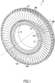
- the invention is applicable to various types of turbomachine rotors, in particular compressor and turbine rotors of different gas turbine bodies, for example a low pressure turbine (LP) impeller, such as that illustrated by FIG. figure 1 .
- LP low pressure turbine
- the figure 1 shows a turbomachine rotor 10 comprising a hub 11 on which is mounted a plurality of blades 100, each blade 100 comprising in a well-known manner a foot 110 formed by a portion of greater thickness, for example section shaped bulb, which is engaged in a corresponding housing 12 formed at the periphery of the hub 11 and a blade 120.
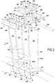
- the rotor comprises a plurality of blade heel elements 200 mounted on each of the blades 100. More specifically, as illustrated in FIGS. figures 2 and 3 the blade 120 extends longitudinally between an inner end 101 of the blade including the foot 110 and its outer end 102 forming the top 140 of the blade 100.
- the blade has in cross section a curved profile of variable thickness delimiting two faces 123 and 124, respectively corresponding to the extrados and the intrados of the blade 120 and each connecting the leading edge. 120 a and the trailing edge 120 b of the latter.
- the blade 120 further comprises a blade platform 150 whose outer (or upper) face 152 delimits, radially inside, the flow vein of a gas flow f. In its upstream and downstream end portions in the flow direction of the gas flow, the platform 150 terminates with overlapping spoilers 154 and 156.
- Each blade heel member 200 here comprises an opening 201 engaged with the outer end of a blade 100.
- the opening 201 has a shape and dimensions adapted to that of the outer end of each blade 100.
- the outer end 102 of each blade 100 which is engaged in an opening 201 of the blade heel member 200 is constituted by a portion 126 which has dimensions smaller than those of the rest of the body of the blade.
- blade 120 so as to define a shoulder 125 forming a bearing surface for the blade heel member 200.
- the blade heel element according to the invention may also comprise openings having a shape and dimensions adapted to the passage of an outer end of blade that has not been reduced relative to the rest of the body of the blade.
- the blade heel member 200 comprises a blade heel spoiler plate 210 and a blade dart plate 220 disposed on the upper face 211 of the nose plate plate 210.
- the blade heel spoiler plate 210 terminates with overlapping spoilers 213 and 214.
- the lower face 212 of the plate nose blade spoiler 210 extends substantially perpendicular to the longitudinal direction of the blade.
- the lower face 212 could be inclined to generally form a non-zero angle to the normal to the longitudinal direction of the blade or the face 212 could have a generally non-rectilinear profile, for example curved.
- the slope of the shoulder 125 is in this case adapted to the shape of the lower face 212 of the plate 210.
- the blade heel plate 220 On its outer (upper) face 222, the blade heel plate 220 defines a depression or bath 223. Along the upstream and downstream edges of the bath 223, the plate 220 carries folded portions forming wipers 224 and 224. 225 having a tooth profile whose ends can penetrate into a layer of abradable material of a turbine ring (not shown) to reduce the clearance between the blade tip and the turbine ring.
- each vane 100 which extends above the blade heel member 200, here portion 126a of the portion 126, includes a lumen 127 in which there is disposed an element or lock key 230 for holding in place the blade heel member 200 on the outer end 102 of the vane 100 particularly with respect to the centrifugal forces.
- the locking element 230 has a length substantially equivalent to that of two blade heel elements 200 so as to be introduced into the slots 127 of two adjacent blades 100 and ensure the maintenance in place of two adjacent heel members 200, the rotor comprising a plurality of locking members 230 distributed over the outer periphery of the vanes formed by the joining of the outer faces 222 of the trays of adjacent 220 blade heel pads.
- the locking element may have a different length allowing it to be introduced into a different number of light, such as for example a single light or more than two lights at a time, and thus to ensure the maintenance of one or more dawn heel elements at the same time.
- the blade heel spoilers tray 210 and the tray 220 of blade heels wipers have in their longitudinal direction D l, similar length while being shifted relative to the other in the same direction.
- D l longitudinal direction
- two offsets 211 and 221 are formed, which allow a partial overlap with the adjacent blade elements 200 and thus improve the sealing of the vein while respecting his profile.
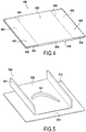
- the figure 4 shows very schematically a fibrous blank 400 for forming the fibrous reinforcement of the blade heel member and from which a fibrous preform of blade heel member can be shaped so, after densification by a die machining, to obtain a blade heel element such as the element 200 illustrated by the figures 2 and 3 .
- the fibrous blank 400 is obtained, as schematically illustrated on the figure 4 by multilayer weaving between a plurality of warp layers and a plurality of weft layers.
- the multilayer weave produced can be in particular an "interlock" weave, that is to say a weave weave in which each layer of weft son binds several layers of warp son with all the son of the same column weft with the same movement in the plane of the armor.
- the blank 400 includes a first and a second portion 410 and 420 for respectively forming the blade heel spoiler plate 210 and the blade heel pad plate 220.
- a first and a second dislocation 401 and 402 are formed inside the fibrous blank between two successive layers of warp threads located at the boundary between the portions 410 and 420 and respectively on two debonding zones 403 and 404.
- the portions 410 and 420 are linked between them at a link zone 405 located between the two debonding zones 403 and 404.
- the delimitations 401 and 402 make it possible to form respectively two parts 421 and 422 which can be folded during the shaping of the blank in order to finally form the wipers 224 and 225 of the dart heel plate 220.
- the figure 5 shows very schematically a fibrous preform 500 of the blade heel element to be manufactured then obtained by molding with deformation of the portion 410 to reproduce shapes similar to those of the blade heel spoiler plate and folding parts 421 and 422 of the portion 420 to reproduce shapes similar to those of the darts of the blade of darts of dawn heel.
- a preform 500 is thus obtained with a portion 510 of blade nose spoiler platform preform and a 520 plate portion of blade heel wipers.
- offsets 511 and 521 are formed respectively at the longitudinal ends of the preform 500.
- the offsets are made by machining after densification of the preform .
- the blank is produced by assembling two fibrous textures respectively corresponding to the spoiler tray and the blade heel plate, the textures can be assembled initially with a corresponding offset.
- the latter are preferably made with fibers and a matrix of the same kind.
- the locking elements 230 may be made of different materials such as a metal material.
- the locking elements are preferably made of composite material having fibers and a matrix of the same nature as those used to make the blades and the blade heel elements.
- the figure 6 shows very schematically a fibrous blank 300 from which a fibrous preform of blade can be shaped so, after densification by a matrix and possible machining, to obtain a composite composite platform blade and integrated heel spoilers platform such as dawn 100 illustrated by the figures 2 and 3 .
- the blank 300 comprises two fibrous webs 302, 304 obtained by three-dimensional weaving or multilayer weaving, only the envelopes of these two parts being shown on the drawing. figure 6 .
- the fibrous web 302 is intended, after shaping, to constitute a part of fibrous preform of blade corresponding to a preform of blade and blade root, this part having a face 302 a intended to form the intrados side of the blade and face 302 b for forming the suction side of the blade.
- the fibrous strip 304 is intended, after shaping, to constitute the portion of fibrous preform of blade corresponding to a platform preform of blade heel.
- the two fibrous webs 302, 304 extend generally in a direction X corresponding to the longitudinal direction of the blade to be produced.
- the fibrous strip 302 has, in its part intended to form a blade preform, a variable thickness determined according to the profile thickness of the blade of the blade to be produced.
- the fibrous band 302 In its part intended to form a foot preform, the fibrous band 302 has an extra thickness 303 determined according to the thickness of the root of the blade to be produced.
- the fibrous web 302 has a width l chosen according to the length of the profile developed (flat) of the blade and the foot of the blade to be made while the fibrous band 304 has a width L greater than 1 chosen according to the developed lengths of the platform to be realized.
- the fibrous band 304 is of substantially constant thickness determined according to the blade platform thicknesses to achieve.
- the strip 304 includes a first portion 304 that extends along and adjacent a first side 302 (lower surface) of the strip 302 and a second portion 304 b which extends along and adjacent to the second b face 302 (top surface) of the strip 302.
- Parts 304 a and 304 b are connected by a connecting portion 340 c which extends transversely to the band 302 at a location corresponding to that of the platform of the vane to achieve.
- the connection portion 340 c passes through the band substantially perpendicularly to the longitudinal direction of the fiber preform.
- the connecting portion 340 c will pass through the web 302 in a non-zero angle to the normal to the longitudinal direction X of the blank.
- the profile of the connecting portion 340 c may be curvilinear instead of being straight as in the example shown.
- the strips 302 and 304 are woven simultaneously by multi-layer weaving, without connection between the band 302 and the portions 304 a and 304 b of the strip 304 and by weaving a plurality of successive blanks 300 so continue in the X direction.
- the Figures 7 to 9 show very schematically how a fibrous preform having a shape close to that of the blade to be manufactured can be obtained from the fiber blank 300.
- the fibrous strip 302 is cut at one end in the excess thickness 303 and at another end to have a strip 320 of length corresponding to the longitudinal dimension of the blade to be manufactured with a bulged portion 330 formed by a portion of the excess thickness 303 and located at a location corresponding to the position of the foot of dawn to manufacture and with an opposite end 350 corresponding to the blade tip to be manufactured.
- the strip 320 having a face 320 is intended to form the lower surface side of the blade and one side 320 b for forming the suction side of the blade.
- cutouts are formed at the ends of the portion 304 a and 304 b in the portion thereof as to leave the sections 340 a and 340 b on both sides of the connecting portion 340 c as shown the figure 7 .
- the lengths of the sections 340 a and 340 b are determined depending on the lengths of the platform in the blade to be manufactured.
- the portions 340 a and 340 b can be folded perpendicular to the strip 302 without cut of threads to form a plate 340 as shown by the figure 8 .
- a fibrous preform 600 of the blade to be manufactured is then obtained by molding with deformation of the band 320 to reproduce the curved profile of the blade of the blade and deformation of the plate 340 to reproduce a shape similar to that of the platform of the dawn, as shown in figure 9 .
- the preform 600 is machined to form a light 627 having a shape and dimensions equivalent to those of the light 127 of the blades to be manufactured.
- a preform 600 is thus obtained with a blade preform portion 620, a foot preform portion 630 (with stilt preform) and a platform preform portion 640.
- the weaving is performed with warp yarns extending in the longitudinal direction X of the blank, being noted that a weaving with weft yarns in this direction is also possible.
- the son used can be silicon carbide (SiC) son provided under the name "Nicalon” by the Japanese company Nippon Carbon and having a title (number of filaments) of 0.5K (500 filaments) .
- SiC silicon carbide
- the weave used can be for example a multilayer weave, made with a satin-like or multi-satin weave.
- Other types of multilayer weaving may be used, for example a multilayer multi-weave weave or interlock weave weave.
- Interlock weaving is here understood to mean a weave in which each layer of weft threads binds several layers of warp yarns with all the threads of the same weft column having the same movement in the plane of the weave. .
- the figure 10A is a perspective sectional chain at the crossing of the strip 302 by the connecting portion 340 c of the strip 304 of the fiber preform to the figure 6 , the warp son of the band 304 in this connecting part being seen in section. Son each warp layer C 304 extends, in this connecting portion 340 c in a direction perpendicular to the direction the belt frame 302.
- the portion of the band 304 from one side to the other of the strip 302 is made, during weaving, by passing through all the warp and weft son of the band 302 by a portion of the son of the C chain son layers 304 of the band 304, individually.
- the layers of warp threads C 304 of the strip 304 penetrate between weft threads 302 of the strip 302 along a straight profile as shown in FIG. figure 10A .
- the strands of chain C 304 of the band 304 can enter and exit the band 302 with profiles of different shapes such as corrugated or curved profiles for example.
- the figure 10B is a perspective cut weft weft son t 302 and t 304 respectively of the strips 302 and 304 at the crossing of the strip 302 by the connecting portion 340 c of the strip 304 of the fiber preform to the figure 3 .
- the connecting portion 340 c extending perpendicular to the direction of the warp layers C son 302 of the strip 302.
- it may have a connection portion 340 c that s' extends by doing a nonzero angle to the normal to the warp direction, depending on the desired orientation of the blade heel platform.
- the excess thickness 303 of the fiber blank 300 of the figure 6 can be obtained using larger title weft yarns and additional weft yarn layers. According to an alternative embodiment, the extra thickness 303 can be obtained by introducing an insert during weaving of the strip 302.
- the layers are bonded together, for example by sewing, by implantation of threads or rigid elements or by needling.
- a fibrous blank for forming the fibrous reinforcement of a blade or blade heel member is woven by multilayer weaving, or by stacking fibrous structures.
- weaves made of ceramic fibers, in particular silicon carbide (SiC) fibers are used for weaving.
- SiC silicon carbide
- carbon fibers can also be used.
- the densification of the fibrous preform intended to form the fibrous reinforcement of the part to be manufactured consists in filling the porosity of the preform, in all or part of the volume thereof, with the material constituting the matrix.
- This densification can be carried out known per se according to the liquid process (CVL) or the gaseous process (CVI), or in a sequence of these two processes.
- the liquid process consists of impregnating the preform with a liquid composition containing a precursor of the matrix material.
- the precursor is usually in the form of a polymer, such as a resin, optionally diluted in a solvent.
- the preform is placed in a mold which can be sealed with a housing having the shape of the molded end piece. Then, the mold is closed and the liquid matrix precursor (for example a resin) is injected throughout the housing to impregnate the entire fibrous portion of the preform.
- the conversion of the precursor into a matrix is carried out by heat treatment, generally by heating the mold, after removal of the optional solvent and crosslinking of the polymer, the preform being always maintained in the mold having a shape corresponding to that of the piece to realize.
- the heat treatment consists in pyrolyzing the precursor to transform the matrix into a carbon or ceramic matrix according to the precursor used and the pyrolysis conditions.
- liquid precursors of ceramics in particular of SiC, may be polycarbosilane (PCS) or polytitanocarbosilane (PTCS) or polysilazane (PSZ) type resins, whereas liquid carbon precursors may be rate resins.
- PCS polycarbosilane
- PTCS polytitanocarbosilane
- PSZ polysilazane
- relatively high coke such as phenolic resins.
- the densification of the fiber preform can be carried out by the well-known method of transfer molding known as RTM ("Resin Transfer Molding").
- RTM Resin Transfer Molding
- the fiber preform is placed in a mold having the external shape of the part to be produced.
- a thermosetting resin is injected into the inner space of the mold which comprises the fibrous preform.
- a pressure gradient is usually established in this internal space between the place where the resin is injected and the evacuation holes of the latter in order to control and optimize the impregnation of the preform with the resin.
- the densification of the fiber preform may also be carried out, in a known manner, by gaseous method by chemical vapor infiltration of the matrix (CVI).
- CVI chemical vapor infiltration of the matrix
- the fiber preform corresponding to the structure to be produced is placed in an oven in which a gaseous reaction phase is admitted.
- the pressure and the temperature prevailing in the furnace and the composition of the gas phase are chosen so as to allow the diffusion of the gas phase within the porosity of the preform to form the matrix by deposition, in the heart of the material in contact with it.
- an SiC matrix can be obtained with methyltrichlorosilane (MTS) giving SiC by decomposition of the MTS while a carbon matrix can be obtained with hydrocarbon gases such as methane and / or propane giving the carbon by cracking.
- MTS methyltrichlorosilane
- hydrocarbon gases such as methane and / or propane giving the carbon by cracking.
- a densification combining liquid route and gaseous route can also be used to facilitate implementation, limit costs and production cycles while obtaining satisfactory characteristics for the intended use.
- the matrix may in particular be obtained from epoxy resins, such as, for example, the high performance epoxy resin, or liquid precursors of carbon or ceramic matrices.
- the fibrous blank is impregnated with a consolidation composition, typically a resin possibly diluted in a solvent.
- a consolidation composition typically a resin possibly diluted in a solvent.
- a carbon precursor resin for example a phenolic or furanic resin
- a ceramic precursor resin for example a polysilazane resin or polysiloxane precursor of SiC.
- Pre-crosslinking or incomplete crosslinking makes it possible to increase the stiffness, and therefore the strength, while preserving the deformation capacity necessary for the production of element preforms: blade heel or blades.
- the fibrous blank in particular that intended to form the blade, is cut, as illustrated by the figure 7 .
- the blank is then shaped (as illustrated by the figure 9 ) and placed in a mold for example in graphite for conformation of the plates of spoilers and blades of blade heel, in the case of the element of blade heel, and of the part of preform of blade and foot of d dawn in the case of dawn.
- crosslinking of the resin is completed and the crosslinked resin is pyrolyzed.
- Crosslinking and pyrolysis can be chained by gradually raising the temperature in the mold.
- a fibrous preform consolidated by the pyrolysis residue is obtained.
- the amount of consolidation resin is chosen so that the pyrolysis residue binds the fibers of the preform sufficiently so that it can be manipulated by maintaining its shape without the assistance of a tool, being noted that the amount of resin consolidation is preferably chosen as low as possible.
- Densification by a matrix of the consolidated preform is then performed.
- the matrix is ceramic, for example SiC.
- the densification can be carried out by CVI, in which case the formation of the second interphase layer and the densification by the matrix can be chained in the same furnace.
- the densification can be carried out in two successive steps separated by a machining step of the blade heel element or blade to the desired dimensions.
- pre-machining in particular to begin forming the opening or openings of the blade heel element and the or the slots or notches on the outer end of the blade, can be achieved after crosslinking and before pyrolysis of the resin.
- the preform can be consolidated by partial densification while being maintained in the shaping, the consolidation being carried out by ceramic deposition on the fibers by CVI.
- the shaper is preferably made of graphite and has holes facilitating the passage of the reaction gas phases giving the interphase deposit and the ceramic deposition by CVI.
- the consolidated preform is extracted from the shaper and the densification by a ceramic matrix by CVI is performed.
- the densification can be carried out in two successive steps separated by a pre-machining step of the blade heel element or blade to the desired dimensions, in particular to begin to form the opening or openings of the heel element dawn and the or lights or notches on the outer end of the blade, a final machining step of these elements being performed after the second densification step.
- variable thickness blade profile by the use of variable son of title and / or texture. It is possible, alternatively, to produce the portion of fiber blank corresponding to the blade preform portion with a number of layers of son of the same title and with fixed thread, the thickness variation of the profile being made during machining after first densification step or during pre-machining of the consolidated blade preform.
- the fibers of the fibrous reinforcement of the blade heel element and the blade may be of a material other than a ceramic, for example carbon, and the matrix may be of a material other than a ceramic, for example carbon or a resin.
- the blade heel element and the blade according to the invention may in particular be made of ceramic matrix composite material (CMC) which is a material formed of a reinforcement of carbon fibers or ceramic densified by at least one matrix partially ceramic such as a carbon-carbon / silicon carbide (CC / SiC), carbon-silicon carbide (C / SiC), silicon carbide silicon carbide (SiC / SiC), or carbon-carbon composite material carbon (C / C) which, in known manner, is a material formed of a carbon fiber reinforcement densified by a carbon matrix.
- CMC ceramic matrix composite material
- the invention is of course also applicable to the manufacture of blade heel element and blades made of organic matrix composite material (CMO) such as that obtained, for example, from a high performance epoxy resin. .
- CMO organic matrix composite material
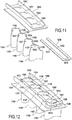
- each blade 1100 comprises, in place of a light, two notches 1127 and 1128 in which arms 1231 and 1232 of a locking element 1230 are engaged in such a way as to hold in position a blade heel member 1200 having apertures, here four apertures 1201 to 1204, into which are engaged the outer ends 1102 of four blades 1100.
- Each locking member 1230 further comprises an abutment member 1233 for cooperating with the free end of the arms 1231 and 1232 of the adjacent locking element allowing, once all the locking elements mounted, to block them in position.
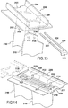
- each blade 2100 comprises two slots 2127 and 2128 in which are engaged arms 2231 and 2232 of a locking element 2230 so as to hold in position a blade heel element 2200 present here two openings 2201 and 2202 in which are engaged the outer ends 2102 of two blades 2100 adjacent.
- Each lock member 2230 further includes a flange 2233 for engaging a housing 2125 at one end of each blade heel member for, once the adjacent blade tone element is mounted as shown in FIG. figure 14 , to lock the locking element in position.
- the housing 2125 is preferably made only in the dart heel plate 1220, which prevents the flange 2233 from entering the flow channel. This does not interfere with flow flow while maintaining a high level of sealing.
- the fibrous blank corresponds to a fibrous structure woven in one piece which incorporates, in addition to a first part intended to form the blade and the foot of the blade, a second part intended to form a dawn platform at least partially nested with the first part (crossing at least part of the first part by threads of the second part).
- the blade according to the invention is not limited to such a blade structure.
- twin-blade structures which comprise two blades linked together, for example at a common platform.
Landscapes
- Engineering & Computer Science (AREA)
- Chemical & Material Sciences (AREA)
- Materials Engineering (AREA)
- Mechanical Engineering (AREA)
- General Engineering & Computer Science (AREA)
- Composite Materials (AREA)
- Ceramic Engineering (AREA)
- Turbine Rotor Nozzle Sealing (AREA)
- Structures Of Non-Positive Displacement Pumps (AREA)
Claims (17)
- Rotor (10) einer Turbomaschine mit mindestens einer Schaufel (100) aus einem Verbundwerkstoff mit einer matrixverdichteten Faserverstärkung, wobei jede Schaufel (100) einen Blattkörper (120) aufweist, der sich zwischen einem inneren Ende (101) mit einem Schaufelfuß (110) und einem äußeren Ende (102) erstreckt, das die Spitze (140) der Schaufel (100) bildet,
dadurch gekennzeichnet, dass er mindestens ein Schaufelabdeckelement (200) aus Verbundwerkstoff mit einer matrixverdichteten Faserverstärkung umfasst, wobei das Schaufelabdeckelement mindestens eine Öffnung (201) umfasst, in die das äußere Ende (102) einer Schaufel (100) eingreift, wobei der Abschnitt (126a) des äußeren Endes (102) jeder Schaufel (100), der sich oberhalb des Schaufelabdeckelements (200) erstreckt, mindestens eine Aussparung oder Kerbe (127) aufweist, in der ein Verriegelungselement (230) angeordnet ist. - Rotor gemäß Anspruch 1, dadurch gekennzeichnet, dass das äußere Ende (102) jeder Schaufel (100) Abmessungen aufweist, die kleiner sind als der darunter liegende Teil des Blattkörpers (120), sodass ein Absatz (125) begrenzt wird, der eine Auflagefläche für das Schaufelabdeckelement (200) bildet.
- Rotor gemäß Anspruch 1 oder 2, dadurch gekennzeichnet, dass jedes Schaufelabdeckelement (200) eine Spoilerplatte der Schaufelabdeckung (210) und eine Zungenplatte der Schaufelabdeckung (220) umfasst.
- Rotor gemäß Anspruch 3, dadurch gekennzeichnet, dass jedes Schaufelabdeckelement (200) an jedem seiner Längsenden einen Versatz (211; 213) aufweist, sodass eine partielle Überlappung zwischen zwei benachbarten Schaufelabdeckelementen ermöglicht wird.
- Rotor gemäß einem der Ansprüche 1 bis 4, dadurch gekennzeichnet, dass jedes Schaufelabdeckelement eine Vielzahl von Öffnungen (1201-1204; 2201, 2202) aufweist, sodass jedes Schaufelabdeckelement (1200; 2200) mit den äußeren Enden (1102; 2102) einer Vielzahl benachbarter Schaufeln (1100; 2100) in Eingriff gebracht wird.
- Rotor gemäß einem der Ansprüche 1 bis 5, dadurch gekennzeichnet, dass das äußere Ende (2102) jeder Schaufel (2100), das sich oberhalb des Schaufelabdeckelements (2200) erstreckt, zwei Aussparungen oder Kerben (2127, 2128) aufweist und dass jedes Verriegelungselement (2230) zwei Arme (2231, 2232) aufweist, die in die Aussparungen bzw. Kerben eingreifen.
- Rotor gemäß einem der Ansprüche 1 bis 6, dadurch gekennzeichnet, dass jedes Verriegelungselement (2230) an einem Ende einen Flansch (2233) aufweist, der mit einer Aufnahme (2125) zusammenwirkt, die in jedem Schaufelabdeckelement vorgesehen ist, um jedes Verriegelungselement in Position zu halten.
- Rotor gemäß einem der Ansprüche 1 bis 7, dadurch gekennzeichnet, dass jede Schaufel ferner ganz oder teilweise eine Schaufelplattform (150) mit oder ohne Spoiler und mit oder ohne Kippschutzwand umfasst.
- Rotor gemäß einem der Ansprüche 1 bis 8, dadurch gekennzeichnet, dass die Faserverstärkung jeder Schaufel durch mehrschichtiges Binden von Fäden erhalten wird.
- Rotor gemäß einem der Ansprüche 1 bis 9, dadurch gekennzeichnet, dass jede Schaufel und jedes Schaufelabdeckelement aus einem Verbundwerkstoff mit keramischer Matrix (CMC) hergestellt ist.
- Rotor gemäß einem der Ansprüche 1 bis 9, dadurch gekennzeichnet, dass jede Schaufel und jedes Schaufelabdeckelement aus einem Verbundwerkstoff mit organischer Matrix (CMO) hergestellt ist.
- Verdichter, ausgestattet der mit einem Rotor gemäß einem der Ansprüche 1 bis 11.
- Turbomaschine mit einem Verdichter gemäß Anspruch 12.
- Verfahren zur Herstellung eines Rotors (10) einer Turbomaschine, umfassend die Herstellung von mindestens einer Schaufel (100), für jede Schaufel umfassend:- Herstellen eines faserstoffhaltigen Schaufelrohlings (300) in einem Stück,- Formen des Faserrohlings, um eine einteilige faserstoffhaltige Vorform der Schaufel (600) zu erhalten, die einen ersten Abschnitt aufweist, der eine Blattvorform (620) und einen Schaufelfuß (630) bildet,- Verdichten der Schaufelvorform (600) durch eine Matrix, um eine Schaufel (100) aus Verbundwerkstoff zu erhalten, die eine faserige Verstärkung aufweist, die durch die Vorform gebildet und durch die Matrix verdichtet wird, und die einen Blattkörper (120) umfasst, der sich zwischen einem inneren Ende (101) mit einem Schaufelfuß (110) und einem äußeren Ende (102) erstreckt, das eine Schaufelspitze (140) bildet,dadurch gekennzeichnet, dass das Verfahren ferner umfasst:- Herstellen von mindestens einer Aussparung oder Kerbe (127) am äußeren Ende (102) jeder Schaufel (100),- Herstellen von mindestens einem Faserrohling (400) in einem einzigen Stück eines Schaufelabdeckelements,- Formen des faserigen Faserrohlings, um eine faserstoffhaltige Vorform (500) des Schaufelabdeckelements zu erhalten,- Verdichten der Vorform des Schaufelabdeckelements durch eine Matrix, um ein Schaufelabdeckelement (200) aus einem Verbundwerkstoff mit einer Faserverstärkung zu erhalten, das aus der Vorform gebildet und durch die Matrix verdichtet ist,- Herstellen von mindestens einer Öffnung (201) in dem Schaufelabdeckelement,- Montieren jeder Schaufel an einer Nabe (11) durch Einrasten des Fußes (110) jeder Schaufel (100) in eine entsprechend geformte Aufnahme (12), die am Umfang der Nabe angeordnet ist,- Montieren jedes Schaufelabdeckelements (200) an mindestens einer Schaufel (100) durch Einrasten des äußeren Endes (102) der Schaufel in die Öffnung oder Kerbe (201) des Schaufelabdeckelements (200),- Anordnen eines Verriegelungselementes (230) in mindestens der Aussparung (127) des äußeren Endes (102) jeder Schaufel (100).
- Verfahren gemäß Anspruch 14, dadurch gekennzeichnet, dass das äußere Ende (102) jeder Schaufel (100) so bearbeitet wird, dass ein Absatz (125) begrenzt wird, der eine Auflagefläche für das Schaufelabdeckelement (200) bildet.
- Verfahren gemäß Anspruch 14 oder 15, dadurch gekennzeichnet, dass jedes Schaufelabdeckelement (200) eine Spoilerplatte der Schaufelabdeckung (210) und eine Zungenplatte der Schaufelabdeckung (220) umfasst.
- Verfahren gemäß Anspruch 16, dadurch gekennzeichnet, dass der Faserrohling jedes Schaufelabdeckelementes (400) durch mehrschichtiges Binden zwischen mehreren Fadenlagen hergestellt wird und dass er partielle Lockerungsbereiche (401, 402) zwischen zwei Reihen benachbarter Fadenlagen aufweist, wobei eine der beiden Reihen von Lagen gefaltet wird, wenn der Rohling so geformt wird, dass er Zungen bildet.
Applications Claiming Priority (2)
| Application Number | Priority Date | Filing Date | Title |
|---|---|---|---|
| FR1154165A FR2975123B1 (fr) | 2011-05-13 | 2011-05-13 | Rotor de turbomachine comprenant des aubes en materiau composite avec talon rapporte |
| PCT/FR2012/051048 WO2012156626A1 (fr) | 2011-05-13 | 2012-05-11 | Rotor de turbomachine comprenant des aubes en materiau composite avec talon rapporte |
Publications (2)
| Publication Number | Publication Date |
|---|---|
| EP2707577A1 EP2707577A1 (de) | 2014-03-19 |
| EP2707577B1 true EP2707577B1 (de) | 2018-03-21 |
Family
ID=46321084
Family Applications (1)
| Application Number | Title | Priority Date | Filing Date |
|---|---|---|---|
| EP12728659.9A Active EP2707577B1 (de) | 2011-05-13 | 2012-05-11 | Turbomaschinenrotor mit schaufeln aus einem verbundstoff und mit zusätzlichem deckband |
Country Status (9)
| Country | Link |
|---|---|
| US (1) | US9790802B2 (de) |
| EP (1) | EP2707577B1 (de) |
| JP (1) | JP2014518976A (de) |
| CN (1) | CN103518038B (de) |
| BR (1) | BR112013029284A2 (de) |
| CA (1) | CA2835539A1 (de) |
| FR (1) | FR2975123B1 (de) |
| RU (1) | RU2013153896A (de) |
| WO (1) | WO2012156626A1 (de) |
Families Citing this family (24)
| Publication number | Priority date | Publication date | Assignee | Title |
|---|---|---|---|---|
| JP6174839B2 (ja) * | 2011-10-14 | 2017-08-02 | 株式会社Ihi | セラミックス基複合部材およびその製造方法 |
| US20140023506A1 (en) * | 2012-07-20 | 2014-01-23 | General Electric Company | Damper system and a turbine |
| EP2964887B1 (de) * | 2013-03-08 | 2019-06-26 | Rolls-Royce North American Technologies, Inc. | Verfahren zur herstellung einer gasturbinen-verbundstoffschaufelanordnung und entsprechende schaufelanordnung |
| GB2521588A (en) * | 2013-10-11 | 2015-07-01 | Reaction Engines Ltd | Turbine blades |
| FR3021349B1 (fr) | 2014-05-22 | 2021-07-02 | Herakles | Procede de fabrication d'une aube de turbomachine en materiau composite, aube ainsi obtenue et turbomachine l'incorporant |
| FR3032648B1 (fr) * | 2015-02-16 | 2017-03-03 | Herakles | Procede de fabrication d'une aube de turbomachine en materiau composite |
| RU2603382C1 (ru) * | 2015-11-25 | 2016-11-27 | Открытое Акционерное Общество "Уфимское Моторостроительное Производственное Объединение" (Оао "Умпо") | Рабочее колесо первой ступени ротора компрессора низкого давления турбореактивного двигателя (варианты) |
| RU2603384C1 (ru) * | 2015-11-25 | 2016-11-27 | Открытое Акционерное Общество "Уфимское Моторостроительное Производственное Объединение" (Оао "Умпо") | Рабочее колесо третьей ступени ротора компрессора низкого давления турбореактивного двигателя (варианты) |
| RU2603377C1 (ru) * | 2015-11-25 | 2016-11-27 | Открытое Акционерное Общество "Уфимское Моторостроительное Производственное Объединение" (Оао "Умпо") | Рабочее колесо ротора компрессора низкого давления газотурбинного двигателя (варианты) |
| US10995040B2 (en) | 2016-03-14 | 2021-05-04 | Rolls-Royce High Temperature Composites, Inc. | Ceramic matrix composite components having a deltoid region and methods for fabricating the same |
| US10294955B2 (en) * | 2016-04-19 | 2019-05-21 | Ge Global Sourcing Llc | Fan apparatus |
| US10710317B2 (en) | 2016-06-16 | 2020-07-14 | Rolls-Royce North American Technologies Inc. | Composite rotatable assembly for an axial-flow compressor |
| US10767502B2 (en) | 2016-12-23 | 2020-09-08 | Rolls-Royce Corporation | Composite turbine vane with three-dimensional fiber reinforcements |
| US10480108B2 (en) | 2017-03-01 | 2019-11-19 | Rolls-Royce Corporation | Ceramic matrix composite components reinforced for managing multi-axial stresses and methods for fabricating the same |
| US10808559B2 (en) | 2018-06-01 | 2020-10-20 | Raytheon Technologies Corporation | Guide vane retention assembly for gas turbine engine |
| US11105209B2 (en) * | 2018-08-28 | 2021-08-31 | General Electric Company | Turbine blade tip shroud |
| US10934870B2 (en) | 2018-09-17 | 2021-03-02 | Rolls Royce Plc | Turbine vane assembly with reinforced end wall joints |
| FR3090030B1 (fr) | 2018-12-12 | 2020-11-20 | Safran Aircraft Engines | Dispositif de maintien pour le démontage d’une roue à aubes de turbomachine et procédé l’utilisant |
| FR3118095B1 (fr) * | 2020-12-18 | 2024-03-29 | Safran Aircraft Engines | Talon d'aube mobile en materiau composite a matrice ceramique en fibres courtes |
| FR3121474B1 (fr) * | 2021-03-30 | 2023-02-17 | Safran Aircraft Engines | Aube comprenant une structure en matériau composite et procédé de fabrication associé |
| GB202303505D0 (en) * | 2023-03-10 | 2023-04-26 | Rolls Royce Plc | Method for manufacturing a composite bladed disk or rotor |
| US12584414B2 (en) * | 2023-08-10 | 2026-03-24 | General Electric Company | Gas turbine engine with composite airfoil and preform core |
| US12576601B2 (en) * | 2024-01-30 | 2026-03-17 | General Electric Company | Composite structure for a turbine engine |
| CN119704556B (zh) * | 2025-02-26 | 2025-06-03 | 北京玻钢院复合材料有限公司 | 一种耐水性热塑性复合材料转子的整体成型模具与方法 |
Family Cites Families (19)
| Publication number | Priority date | Publication date | Assignee | Title |
|---|---|---|---|---|
| US764450A (en) * | 1903-12-19 | 1904-07-05 | Gen Electric | Turbine-bucket cover. |
| GB695724A (en) | 1950-08-01 | 1953-08-19 | Rolls Royce | Improvements in or relating to structural elements for axial-flow turbo-machines such as compressors or turbines of gas-turbine engines |
| FR1055160A (fr) | 1951-04-24 | 1954-02-16 | Abbott Lab | Procédé de préparation de composés chimiques de la classe des 8-(4-aminobutyl-amino)-6-méthoxyquinoléines |
| FR1055161A (fr) | 1952-04-24 | 1954-02-16 | Etanlux | Couloir oscillant, notamment pour le transport du charbon |
| US2959393A (en) | 1956-04-16 | 1960-11-08 | Gen Electric | Turbine bucket cover assembly |
| US3053505A (en) * | 1958-06-11 | 1962-09-11 | Gen Motors Corp | Pinned blade shrouding |
| US3065955A (en) * | 1958-12-29 | 1962-11-27 | Gen Electric | Rotor blade and shroud assembly |
| FR2612249B1 (fr) | 1987-03-12 | 1992-02-07 | Alsthom | Aubage mobile pour turbines a vapeur |
| JPH07279606A (ja) | 1994-04-08 | 1995-10-27 | Hitachi Ltd | タービン動翼装置 |
| JP3978766B2 (ja) * | 2001-11-12 | 2007-09-19 | 株式会社Ihi | バンド部付きセラミックス基複合部材とその製造方法 |
| JP3983553B2 (ja) | 2002-01-21 | 2007-09-26 | 本田技研工業株式会社 | 整流部材 |
| US20060093847A1 (en) | 2004-11-02 | 2006-05-04 | United Technologies Corporation | Composite sandwich with improved ballistic toughness |
| FR2887601B1 (fr) | 2005-06-24 | 2007-10-05 | Snecma Moteurs Sa | Piece mecanique et procede de fabrication d'une telle piece |
| GB0519502D0 (en) * | 2005-09-24 | 2005-11-02 | Rolls Royce Plc | Vane assembly |
| US7510379B2 (en) * | 2005-12-22 | 2009-03-31 | General Electric Company | Composite blading member and method for making |
| JP2007332893A (ja) | 2006-06-16 | 2007-12-27 | Mitsubishi Heavy Ind Ltd | 軸流タービン翼の制振及びフレッティング防止構造 |
| FR2928963B1 (fr) * | 2008-03-19 | 2017-12-08 | Snecma | Distributeur de turbine pour une turbomachine. |
| FR2939129B1 (fr) | 2008-11-28 | 2014-08-22 | Snecma Propulsion Solide | Aube de turbomachine en materiau composite et procede pour sa fabrication. |
| FR2943942B1 (fr) | 2009-04-06 | 2016-01-29 | Snecma | Procede de fabrication d'une aube de turbomachine en materiau composite |
-
2011
- 2011-05-13 FR FR1154165A patent/FR2975123B1/fr active Active
-
2012
- 2012-05-11 WO PCT/FR2012/051048 patent/WO2012156626A1/fr not_active Ceased
- 2012-05-11 JP JP2014509801A patent/JP2014518976A/ja active Pending
- 2012-05-11 US US14/117,507 patent/US9790802B2/en active Active
- 2012-05-11 RU RU2013153896/06A patent/RU2013153896A/ru unknown
- 2012-05-11 BR BR112013029284A patent/BR112013029284A2/pt not_active IP Right Cessation
- 2012-05-11 CN CN201280022649.2A patent/CN103518038B/zh not_active Expired - Fee Related
- 2012-05-11 CA CA2835539A patent/CA2835539A1/en not_active Abandoned
- 2012-05-11 EP EP12728659.9A patent/EP2707577B1/de active Active
Also Published As
| Publication number | Publication date |
|---|---|
| EP2707577A1 (de) | 2014-03-19 |
| WO2012156626A1 (fr) | 2012-11-22 |
| FR2975123B1 (fr) | 2013-06-14 |
| US9790802B2 (en) | 2017-10-17 |
| CN103518038A (zh) | 2014-01-15 |
| US20140205463A1 (en) | 2014-07-24 |
| CN103518038B (zh) | 2016-10-12 |
| BR112013029284A2 (pt) | 2017-09-26 |
| FR2975123A1 (fr) | 2012-11-16 |
| RU2013153896A (ru) | 2015-06-20 |
| JP2014518976A (ja) | 2014-08-07 |
| CA2835539A1 (en) | 2012-11-22 |
Similar Documents
| Publication | Publication Date | Title |
|---|---|---|
| EP2707577B1 (de) | Turbomaschinenrotor mit schaufeln aus einem verbundstoff und mit zusätzlichem deckband | |
| EP2707578B1 (de) | Turbomaschinen-verbundschaufel mit integriertem fuss | |
| EP2416944B1 (de) | Verfahren zur herstellung einer aus einem verbundmaterial hergestellten turbomaschinenschaufel | |
| EP2785980B1 (de) | Turbinenschaufel mit hohlem schaufelblatt aus verbundstoff, turbine oder kompressor mit einer leitschaufelanordnung aus solchen schaufeln und turbomaschine damit | |
| EP3259123B1 (de) | Verfahren zur herstellung einer aus einem verbundstoffmaterial hergestellten turbomaschinenschaufel | |
| EP2349688B1 (de) | Verbundmaterial turbomotorleitschaufel und herstellungsverfahren dafür | |
| EP2585281B1 (de) | Turbomaschinenschaufel mit gleichmässiger/ungleichmässiger komplementärer geometrie und herstellungsverfahren dafür | |
| EP3114324B1 (de) | Statorabschnitt für eine turbomaschine und verfahren zur herstellung davon | |
| EP2513427B1 (de) | Turbinenmotor-rotorblatt aus verbundwerkstoff und herstellungsverfahren dafür | |
| EP2771547B1 (de) | Verfahren zur herstellung eines turbinendüsen-leitschaufelabschnitts oder eines kompressorleitschaufelabschnitts aus einem verbundwerkstoff für eine turbomaschine | |
| EP2723992B1 (de) | Turbinenmotorteil als kompressorstator oder turbinendüse und herstellungsverfahren dafür | |
| EP2585280B1 (de) | Turbomaschinenschaufel mit komplementärer asymmetrischer geometrie | |
| FR2955609A1 (fr) | Aube composite a canaux internes | |
| EP4301917A1 (de) | Faserstruktur für eine kompositklinge mit dünnen rändern |
Legal Events
| Date | Code | Title | Description |
|---|---|---|---|
| PUAI | Public reference made under article 153(3) epc to a published international application that has entered the european phase |
Free format text: ORIGINAL CODE: 0009012 |
|
| 17P | Request for examination filed |
Effective date: 20131025 |
|
| AK | Designated contracting states |
Kind code of ref document: A1 Designated state(s): AL AT BE BG CH CY CZ DE DK EE ES FI FR GB GR HR HU IE IS IT LI LT LU LV MC MK MT NL NO PL PT RO RS SE SI SK SM TR |
|
| DAX | Request for extension of the european patent (deleted) | ||
| RAP1 | Party data changed (applicant data changed or rights of an application transferred) |
Owner name: SNECMA Owner name: SAFRAN CERAMICS |
|
| GRAP | Despatch of communication of intention to grant a patent |
Free format text: ORIGINAL CODE: EPIDOSNIGR1 |
|
| INTG | Intention to grant announced |
Effective date: 20171024 |
|
| RAP1 | Party data changed (applicant data changed or rights of an application transferred) |
Owner name: SAFRAN AIRCRAFT ENGINES |
|
| GRAS | Grant fee paid |
Free format text: ORIGINAL CODE: EPIDOSNIGR3 |
|
| GRAA | (expected) grant |
Free format text: ORIGINAL CODE: 0009210 |
|
| AK | Designated contracting states |
Kind code of ref document: B1 Designated state(s): AL AT BE BG CH CY CZ DE DK EE ES FI FR GB GR HR HU IE IS IT LI LT LU LV MC MK MT NL NO PL PT RO RS SE SI SK SM TR |
|
| REG | Reference to a national code |
Ref country code: GB Ref legal event code: FG4D Free format text: NOT ENGLISH |
|
| REG | Reference to a national code |
Ref country code: CH Ref legal event code: EP |
|
| REG | Reference to a national code |
Ref country code: AT Ref legal event code: REF Ref document number: 981339 Country of ref document: AT Kind code of ref document: T Effective date: 20180415 |
|
| REG | Reference to a national code |
Ref country code: IE Ref legal event code: FG4D Free format text: LANGUAGE OF EP DOCUMENT: FRENCH |
|
| REG | Reference to a national code |
Ref country code: DE Ref legal event code: R096 Ref document number: 602012044188 Country of ref document: DE |
|
| REG | Reference to a national code |
Ref country code: FR Ref legal event code: PLFP Year of fee payment: 7 |
|
| REG | Reference to a national code |
Ref country code: SE Ref legal event code: TRGR |
|
| REG | Reference to a national code |
Ref country code: NL Ref legal event code: MP Effective date: 20180321 |
|
| PG25 | Lapsed in a contracting state [announced via postgrant information from national office to epo] |
Ref country code: LT Free format text: LAPSE BECAUSE OF FAILURE TO SUBMIT A TRANSLATION OF THE DESCRIPTION OR TO PAY THE FEE WITHIN THE PRESCRIBED TIME-LIMIT Effective date: 20180321 Ref country code: HR Free format text: LAPSE BECAUSE OF FAILURE TO SUBMIT A TRANSLATION OF THE DESCRIPTION OR TO PAY THE FEE WITHIN THE PRESCRIBED TIME-LIMIT Effective date: 20180321 Ref country code: NO Free format text: LAPSE BECAUSE OF FAILURE TO SUBMIT A TRANSLATION OF THE DESCRIPTION OR TO PAY THE FEE WITHIN THE PRESCRIBED TIME-LIMIT Effective date: 20180621 Ref country code: FI Free format text: LAPSE BECAUSE OF FAILURE TO SUBMIT A TRANSLATION OF THE DESCRIPTION OR TO PAY THE FEE WITHIN THE PRESCRIBED TIME-LIMIT Effective date: 20180321 Ref country code: CY Free format text: LAPSE BECAUSE OF FAILURE TO SUBMIT A TRANSLATION OF THE DESCRIPTION OR TO PAY THE FEE WITHIN THE PRESCRIBED TIME-LIMIT Effective date: 20180321 |
|
| REG | Reference to a national code |
Ref country code: LT Ref legal event code: MG4D |
|
| REG | Reference to a national code |
Ref country code: AT Ref legal event code: MK05 Ref document number: 981339 Country of ref document: AT Kind code of ref document: T Effective date: 20180321 |
|
| PG25 | Lapsed in a contracting state [announced via postgrant information from national office to epo] |
Ref country code: LV Free format text: LAPSE BECAUSE OF FAILURE TO SUBMIT A TRANSLATION OF THE DESCRIPTION OR TO PAY THE FEE WITHIN THE PRESCRIBED TIME-LIMIT Effective date: 20180321 Ref country code: GR Free format text: LAPSE BECAUSE OF FAILURE TO SUBMIT A TRANSLATION OF THE DESCRIPTION OR TO PAY THE FEE WITHIN THE PRESCRIBED TIME-LIMIT Effective date: 20180622 Ref country code: BG Free format text: LAPSE BECAUSE OF FAILURE TO SUBMIT A TRANSLATION OF THE DESCRIPTION OR TO PAY THE FEE WITHIN THE PRESCRIBED TIME-LIMIT Effective date: 20180621 Ref country code: RS Free format text: LAPSE BECAUSE OF FAILURE TO SUBMIT A TRANSLATION OF THE DESCRIPTION OR TO PAY THE FEE WITHIN THE PRESCRIBED TIME-LIMIT Effective date: 20180321 |
|
| PG25 | Lapsed in a contracting state [announced via postgrant information from national office to epo] |
Ref country code: MT Free format text: LAPSE BECAUSE OF FAILURE TO SUBMIT A TRANSLATION OF THE DESCRIPTION OR TO PAY THE FEE WITHIN THE PRESCRIBED TIME-LIMIT Effective date: 20180321 |
|
| PG25 | Lapsed in a contracting state [announced via postgrant information from national office to epo] |
Ref country code: AL Free format text: LAPSE BECAUSE OF FAILURE TO SUBMIT A TRANSLATION OF THE DESCRIPTION OR TO PAY THE FEE WITHIN THE PRESCRIBED TIME-LIMIT Effective date: 20180321 Ref country code: PL Free format text: LAPSE BECAUSE OF FAILURE TO SUBMIT A TRANSLATION OF THE DESCRIPTION OR TO PAY THE FEE WITHIN THE PRESCRIBED TIME-LIMIT Effective date: 20180321 Ref country code: EE Free format text: LAPSE BECAUSE OF FAILURE TO SUBMIT A TRANSLATION OF THE DESCRIPTION OR TO PAY THE FEE WITHIN THE PRESCRIBED TIME-LIMIT Effective date: 20180321 Ref country code: ES Free format text: LAPSE BECAUSE OF FAILURE TO SUBMIT A TRANSLATION OF THE DESCRIPTION OR TO PAY THE FEE WITHIN THE PRESCRIBED TIME-LIMIT Effective date: 20180321 Ref country code: RO Free format text: LAPSE BECAUSE OF FAILURE TO SUBMIT A TRANSLATION OF THE DESCRIPTION OR TO PAY THE FEE WITHIN THE PRESCRIBED TIME-LIMIT Effective date: 20180321 Ref country code: NL Free format text: LAPSE BECAUSE OF FAILURE TO SUBMIT A TRANSLATION OF THE DESCRIPTION OR TO PAY THE FEE WITHIN THE PRESCRIBED TIME-LIMIT Effective date: 20180321 |
|
| PG25 | Lapsed in a contracting state [announced via postgrant information from national office to epo] |
Ref country code: SM Free format text: LAPSE BECAUSE OF FAILURE TO SUBMIT A TRANSLATION OF THE DESCRIPTION OR TO PAY THE FEE WITHIN THE PRESCRIBED TIME-LIMIT Effective date: 20180321 Ref country code: AT Free format text: LAPSE BECAUSE OF FAILURE TO SUBMIT A TRANSLATION OF THE DESCRIPTION OR TO PAY THE FEE WITHIN THE PRESCRIBED TIME-LIMIT Effective date: 20180321 Ref country code: CZ Free format text: LAPSE BECAUSE OF FAILURE TO SUBMIT A TRANSLATION OF THE DESCRIPTION OR TO PAY THE FEE WITHIN THE PRESCRIBED TIME-LIMIT Effective date: 20180321 Ref country code: SK Free format text: LAPSE BECAUSE OF FAILURE TO SUBMIT A TRANSLATION OF THE DESCRIPTION OR TO PAY THE FEE WITHIN THE PRESCRIBED TIME-LIMIT Effective date: 20180321 |
|
| REG | Reference to a national code |
Ref country code: CH Ref legal event code: PL |
|
| PG25 | Lapsed in a contracting state [announced via postgrant information from national office to epo] |
Ref country code: PT Free format text: LAPSE BECAUSE OF FAILURE TO SUBMIT A TRANSLATION OF THE DESCRIPTION OR TO PAY THE FEE WITHIN THE PRESCRIBED TIME-LIMIT Effective date: 20180723 |
|
| REG | Reference to a national code |
Ref country code: DE Ref legal event code: R097 Ref document number: 602012044188 Country of ref document: DE |
|
| PLBE | No opposition filed within time limit |
Free format text: ORIGINAL CODE: 0009261 |
|
| STAA | Information on the status of an ep patent application or granted ep patent |
Free format text: STATUS: NO OPPOSITION FILED WITHIN TIME LIMIT |
|
| REG | Reference to a national code |
Ref country code: BE Ref legal event code: MM Effective date: 20180531 |
|
| PG25 | Lapsed in a contracting state [announced via postgrant information from national office to epo] |
Ref country code: DK Free format text: LAPSE BECAUSE OF FAILURE TO SUBMIT A TRANSLATION OF THE DESCRIPTION OR TO PAY THE FEE WITHIN THE PRESCRIBED TIME-LIMIT Effective date: 20180321 Ref country code: MC Free format text: LAPSE BECAUSE OF FAILURE TO SUBMIT A TRANSLATION OF THE DESCRIPTION OR TO PAY THE FEE WITHIN THE PRESCRIBED TIME-LIMIT Effective date: 20180321 |
|
| REG | Reference to a national code |
Ref country code: IE Ref legal event code: MM4A |
|
| 26N | No opposition filed |
Effective date: 20190102 |
|
| PG25 | Lapsed in a contracting state [announced via postgrant information from national office to epo] |
Ref country code: LI Free format text: LAPSE BECAUSE OF NON-PAYMENT OF DUE FEES Effective date: 20180531 Ref country code: CH Free format text: LAPSE BECAUSE OF NON-PAYMENT OF DUE FEES Effective date: 20180531 |
|
| PG25 | Lapsed in a contracting state [announced via postgrant information from national office to epo] |
Ref country code: LU Free format text: LAPSE BECAUSE OF NON-PAYMENT OF DUE FEES Effective date: 20180511 |
|
| PG25 | Lapsed in a contracting state [announced via postgrant information from national office to epo] |
Ref country code: IE Free format text: LAPSE BECAUSE OF NON-PAYMENT OF DUE FEES Effective date: 20180511 |
|
| PG25 | Lapsed in a contracting state [announced via postgrant information from national office to epo] |
Ref country code: BE Free format text: LAPSE BECAUSE OF NON-PAYMENT OF DUE FEES Effective date: 20180531 Ref country code: SI Free format text: LAPSE BECAUSE OF FAILURE TO SUBMIT A TRANSLATION OF THE DESCRIPTION OR TO PAY THE FEE WITHIN THE PRESCRIBED TIME-LIMIT Effective date: 20180321 |
|
| PG25 | Lapsed in a contracting state [announced via postgrant information from national office to epo] |
Ref country code: TR Free format text: LAPSE BECAUSE OF FAILURE TO SUBMIT A TRANSLATION OF THE DESCRIPTION OR TO PAY THE FEE WITHIN THE PRESCRIBED TIME-LIMIT Effective date: 20180321 |
|
| PG25 | Lapsed in a contracting state [announced via postgrant information from national office to epo] |
Ref country code: HU Free format text: LAPSE BECAUSE OF FAILURE TO SUBMIT A TRANSLATION OF THE DESCRIPTION OR TO PAY THE FEE WITHIN THE PRESCRIBED TIME-LIMIT; INVALID AB INITIO Effective date: 20120511 |
|
| PG25 | Lapsed in a contracting state [announced via postgrant information from national office to epo] |
Ref country code: MK Free format text: LAPSE BECAUSE OF NON-PAYMENT OF DUE FEES Effective date: 20180321 |
|
| PG25 | Lapsed in a contracting state [announced via postgrant information from national office to epo] |
Ref country code: IS Free format text: LAPSE BECAUSE OF FAILURE TO SUBMIT A TRANSLATION OF THE DESCRIPTION OR TO PAY THE FEE WITHIN THE PRESCRIBED TIME-LIMIT Effective date: 20180721 |
|
| PGFP | Annual fee paid to national office [announced via postgrant information from national office to epo] |
Ref country code: DE Payment date: 20250519 Year of fee payment: 14 |
|
| PGFP | Annual fee paid to national office [announced via postgrant information from national office to epo] |
Ref country code: GB Payment date: 20250527 Year of fee payment: 14 |
|
| PGFP | Annual fee paid to national office [announced via postgrant information from national office to epo] |
Ref country code: IT Payment date: 20250530 Year of fee payment: 14 |
|
| PGFP | Annual fee paid to national office [announced via postgrant information from national office to epo] |
Ref country code: FR Payment date: 20250526 Year of fee payment: 14 |
|
| PGFP | Annual fee paid to national office [announced via postgrant information from national office to epo] |
Ref country code: SE Payment date: 20250522 Year of fee payment: 14 |