EP2707603B1 - Vorrichtung für geregelte gasabgabe, im besonderen für ein atemgerät - Google Patents
Vorrichtung für geregelte gasabgabe, im besonderen für ein atemgerät Download PDFInfo
- Publication number
- EP2707603B1 EP2707603B1 EP12710655.7A EP12710655A EP2707603B1 EP 2707603 B1 EP2707603 B1 EP 2707603B1 EP 12710655 A EP12710655 A EP 12710655A EP 2707603 B1 EP2707603 B1 EP 2707603B1
- Authority
- EP
- European Patent Office
- Prior art keywords
- casing
- motor
- fan
- gas
- motor casing
- Prior art date
- Legal status (The legal status is an assumption and is not a legal conclusion. Google has not performed a legal analysis and makes no representation as to the accuracy of the status listed.)
- Active
Links
Images



Classifications
-
- A—HUMAN NECESSITIES
- A61—MEDICAL OR VETERINARY SCIENCE; HYGIENE
- A61M—DEVICES FOR INTRODUCING MEDIA INTO, OR ONTO, THE BODY; DEVICES FOR TRANSDUCING BODY MEDIA OR FOR TAKING MEDIA FROM THE BODY; DEVICES FOR PRODUCING OR ENDING SLEEP OR STUPOR
- A61M16/00—Devices for influencing the respiratory system of patients by gas treatment, e.g. ventilators; Tracheal tubes
- A61M16/0057—Pumps therefor
- A61M16/0066—Blowers or centrifugal pumps
-
- F—MECHANICAL ENGINEERING; LIGHTING; HEATING; WEAPONS; BLASTING
- F04—POSITIVE - DISPLACEMENT MACHINES FOR LIQUIDS; PUMPS FOR LIQUIDS OR ELASTIC FLUIDS
- F04D—NON-POSITIVE-DISPLACEMENT PUMPS
- F04D25/00—Pumping installations or systems
- F04D25/02—Units comprising pumps and their driving means
- F04D25/08—Units comprising pumps and their driving means the working fluid being air, e.g. for ventilation
- F04D25/082—Units comprising pumps and their driving means the working fluid being air, e.g. for ventilation the unit having provision for cooling the motor
-
- F—MECHANICAL ENGINEERING; LIGHTING; HEATING; WEAPONS; BLASTING
- F04—POSITIVE - DISPLACEMENT MACHINES FOR LIQUIDS; PUMPS FOR LIQUIDS OR ELASTIC FLUIDS
- F04D—NON-POSITIVE-DISPLACEMENT PUMPS
- F04D29/00—Details, component parts, or accessories
- F04D29/58—Cooling; Heating; Diminishing heat transfer
- F04D29/5806—Cooling the drive system
-
- F—MECHANICAL ENGINEERING; LIGHTING; HEATING; WEAPONS; BLASTING
- F04—POSITIVE - DISPLACEMENT MACHINES FOR LIQUIDS; PUMPS FOR LIQUIDS OR ELASTIC FLUIDS
- F04D—NON-POSITIVE-DISPLACEMENT PUMPS
- F04D29/00—Details, component parts, or accessories
- F04D29/58—Cooling; Heating; Diminishing heat transfer
- F04D29/582—Cooling; Heating; Diminishing heat transfer specially adapted for elastic fluid pumps
- F04D29/584—Cooling; Heating; Diminishing heat transfer specially adapted for elastic fluid pumps cooling or heating the machine
-
- A—HUMAN NECESSITIES
- A61—MEDICAL OR VETERINARY SCIENCE; HYGIENE
- A61M—DEVICES FOR INTRODUCING MEDIA INTO, OR ONTO, THE BODY; DEVICES FOR TRANSDUCING BODY MEDIA OR FOR TAKING MEDIA FROM THE BODY; DEVICES FOR PRODUCING OR ENDING SLEEP OR STUPOR
- A61M2205/00—General characteristics of the apparatus
- A61M2205/33—Controlling, regulating or measuring
- A61M2205/3368—Temperature
-
- A—HUMAN NECESSITIES
- A61—MEDICAL OR VETERINARY SCIENCE; HYGIENE
- A61M—DEVICES FOR INTRODUCING MEDIA INTO, OR ONTO, THE BODY; DEVICES FOR TRANSDUCING BODY MEDIA OR FOR TAKING MEDIA FROM THE BODY; DEVICES FOR PRODUCING OR ENDING SLEEP OR STUPOR
- A61M2205/00—General characteristics of the apparatus
- A61M2205/36—General characteristics of the apparatus related to heating or cooling
- A61M2205/3606—General characteristics of the apparatus related to heating or cooling cooled
-
- A—HUMAN NECESSITIES
- A61—MEDICAL OR VETERINARY SCIENCE; HYGIENE
- A61M—DEVICES FOR INTRODUCING MEDIA INTO, OR ONTO, THE BODY; DEVICES FOR TRANSDUCING BODY MEDIA OR FOR TAKING MEDIA FROM THE BODY; DEVICES FOR PRODUCING OR ENDING SLEEP OR STUPOR
- A61M2205/00—General characteristics of the apparatus
- A61M2205/36—General characteristics of the apparatus related to heating or cooling
- A61M2205/362—General characteristics of the apparatus related to heating or cooling by gas flow
-
- A—HUMAN NECESSITIES
- A61—MEDICAL OR VETERINARY SCIENCE; HYGIENE
- A61M—DEVICES FOR INTRODUCING MEDIA INTO, OR ONTO, THE BODY; DEVICES FOR TRANSDUCING BODY MEDIA OR FOR TAKING MEDIA FROM THE BODY; DEVICES FOR PRODUCING OR ENDING SLEEP OR STUPOR
- A61M2205/00—General characteristics of the apparatus
- A61M2205/42—Reducing noise
Definitions
- the present invention concerns apparatus for regulated delivery of a gas, notably respiratory assistance apparatus.
- apparatus for regulated delivery of a gas notably respiratory assistance apparatus, comprising:
- Such respiratory assistance apparatus must be able to operate over a wide range of flow rates, and in particular be capable of delivering a low flow rate of gas (for neonatal or paediatric use).
- the type of fan motor used in such apparatus and likewise the fast rotation of that motor, induce high heating of the motor, particularly when the fan is delivering a low flow rate.
- this heating is accentuated if the motor casing is closed at said second end by a transverse wall including a lower bearing guiding the shaft of the motor.
- this lower transverse wall is solid and completely closes the lower portion of the motor casing, which is not favourable for good cooling of the motor.
- a main object of the present invention is to remedy this essential drawback and consequently to provide apparatus as referred to above having improved performance and increased longevity.
- Another drawback of existing apparatus is the risk in the event of overheating of the motor of generating possibly toxic smoke, even polluting the air delivered by the fan, and another objective of the invention is to remedy this drawback.
- a further objective of the invention is to facilitate mounting the fan in a casing receiving the fan.
- a further objective of the invention is to cool the motor without degrading the operation of the lower bearing of the motor shaft.
- the apparatus concerned comprises, in a manner that is known in itself:
- Said clear separation also has the decisive advantage, in the event of overheating of the motor, of eliminating the risk of pollution of the gas delivered by the fan to the patient during use of the apparatus for respiratory assistance (this excludes the variant described hereinafter in which the gas is recirculated in the fan scroll).
- the aforementioned cooling gas could be constituted of a gas different from the gas delivered by the apparatus, flowing in a dedicated circuit.
- this cooling gas is preferably constituted by a portion of the gas delivered by the apparatus, said first hole or holes communicating with the interior of the fan scroll so that a portion of the gas under pressure delivered by the apparatus passes through said first hole or holes, then passes through the motor casing, and flows to the outside of the motor casing via said second hole or holes.
- said first end of the motor casing fits in an opening that the bottom of the fan scroll comprises so that said first hole or each first hole that it comprises opens directly into the fan scroll and is situated immediately below the impeller.
- the apparatus of the invention preferably comprises a soundproofing casing around said receiving casing and rigidly fastened thereto; this soundproofing casing may comprise a conduit for direct evacuation to the outside of the cooling gas that has passed through the motor casing, toward the exterior, which is suitable if the gas used has no commercial value, in particular if that gas is air; this soundproofing casing may alternatively comprise an orifice or conduit for recirculation of this cooling gas that has passed through the motor casing toward the fan scroll, which is suitable if the gas used has a significant commercial value, in particular if that gas is oxygen.
- the fan preferably comprises a sealing part isolating said second hole or holes from said inlet for admission of gas into said space.
- This sealing part may notably take the form of a skirt a first tubular portion of which fits around the peripheral wall of the motor casing, said second hole or holes being arranged outside the area of application of this first tubular portion against this peripheral wall, notably in a transverse end wall that this casing includes.
- This second hole or each second hole thus opens onto the interior side of the sealing skirt whereas said inlet to said space is situated on the exterior side of that said sealing skirt.
- said sealing skirt comprises a second tubular portion fixed to this soundproofing casing.
- sealing skirt is connected to the motor casing by its first tubular part and to the soundproofing casing by its second tubular part, and in this way enables mounting of the fan in said receiving casing.
- the sealing skirt preferably comprises an intermediate third tubular portion between said first and second tubular portions and flexibly connecting these first and second tubular portions.
- This flexibility enables filtering of vibrations generated by the fan, as much in a direction parallel to the rotation axis of the shaft of the motor as in radial directions relative to that said rotation axis.
- This third tubular portion may notably be formed by a thin wall connected to the radially internal wall of said first tubular portion and to the radially internal wall of said second tubular portion.
- the fan comprises, at said second end of the motor casing, a bearing guiding the shaft of the motor
- the motor casing comprises a covering wall completely covering this bearing and thus eliminating any possibility of the cooling gas passing through this bearing.
- said covering wall is formed by a cap mounted on this transverse wall, covering the whole of the portion of the shaft of the motor that is extended beyond said transverse wall and said bearing.
- the apparatus preferably comprises a sealing part a first tubular portion around said tube, a second tubular portion whereof is mounted in a soundproofing casing containing said receiving casing, and an intermediate third tubular portion between said first and second tubular portions is connected to these first and second tubular portions.
- This sealing skirt also simplifies mounting the fan in the soundproofing casing and filters vibrations generated by this fan.
- the casing receiving the fan advantageously has a shape that espouses that of the motor casing and that of the fan scroll so that the wall of this receiving casing is at a substantially constant distance from the wall of this motor casing and the wall of this fan scroll.
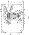
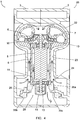
- Figures 1 to 4 shows respiratory assistance apparatus 1 comprising a fan 2 and two half-casings 3 adapted to be assembled together around this fan 2.
- the fan 2 is essentially constituted by a motor 5, an impeller 6 driven by the motor 5, and a fan scroll 7 containing this impeller 6.
- the motor 5 is of cylindrical general shape and comprises an axial shaft on which the impeller 6 is mounted. It is contained in a motor casing 8 have a first end connected to the fan scroll 7 and a second end situated on the side opposite the fan scroll 7. This first end of the casing 8 fits in an opening in the bottom of the fan scroll 7 and is connected to a mounting plate, this mounting plate and this first end comprising a plurality of first holes 10 arranged in a circle concentric with the shaft of the motor 5. Said second end of the casing 8 comprises a transverse wall comprising a plurality of second holes 11 arranged in a circle concentric with the shaft of the motor 5 and comprising a bearing 12 for guiding an extension 13 of this shaft of the motor 5.
- This extension 13 includes a balancing weight 14 and, like the bearing 12, is entirely covered by a cap 15.
- the peripheral wall of this cap is situated entirely inside the circle on which the holes 11 are disposed so that it does not cover these holes 11.
- the impeller 6 has an axial gas inlet disposed in the inlet of the fan scroll 7, gas flow conduits delimited by the impeller blades, and peripheral outlets.
- the fan scroll 7 comprises an axial gas inlet, an annular body and a gas outlet tube 16.
- the fan 2 also comprises a lug 17 for registering the fan 2 relative to a receiving casing described hereinafter, this lug 17 being rigidly fastened to the fan scroll 7.
- This lug 17 has a substantially cylindrical shape and extends radially toward the exterior of the fan scroll 7, being situated at a location diametrically opposite the tube 16.
- the two half-casings 3 each form a half-casing 20 receiving the fan 2 and a soundproofing half-casing 21, these half-casings 20 and 21 being, in the example shown, produced by moulding and in one piece.
- the two half-casings 20 After assembling the two half-casings 3 (see Figure 4 ), the two half-casings 20 form a receiving casing 22 for the fan 2 defining, around this fan, a fan cooling gas flow space 23 having a gas inlet 24 situated at said second end of the motor casing 8.
- This conduit 31 is formed of two demi-conduits moulded in one piece with the two half-casings 3.
- the structure 29 for mounting the fan 2 receives an elastomer sealing part 35 taking the form of a skirt.
- This skirt comprises a first tubular part 35a that fits around the peripheral wall of the motor casing 8, a second tubular part 35b that is a close fit in a lower groove formed by the structure 29, and an intermediate third tubular part 35c between said first and second tubular parts 35a, 35b.
- This third tubular part 35c is formed by a thin wall connected to the radially internal edge of said first tubular part 35a and to the radially internal edge of said second tubular part 35b and flexibly connects these first and second tubular parts 35a, 35b.
- the structure 30 for mounting the tube 16 also receives a sealing part 36 having a structure similar to that of the part 35, with a first portion that is a close fit around the tube 16, a second portion that is a close fit in a receiving groove formed by the structure 30, and a flexible intermediate tubular part.
- the lug 17 receives an O-ring 37 through which it bears against the receiving casing 22, which completes assembly of the fan 2.
- sealing part 35 also has the decisive advantage, in the event of overheating of the motor 5, of eliminating the risk of pollution of the gas delivered by the fan 2 to the patent during use of the apparatus 1 for respiratory assistance.
- the sealing parts 35 and 36 for their part facilitate and simplify mounting the fan 2 in the receiving casing 22 and the soundproofing casing 25, with filtering of vibration of this fan thanks to said flexible intermediate portions that these sealing parts comprise.
- the cap 15 eliminates all possibility of the cooling gas passing through the bearing 15 and thus eliminates all risk of the grease in this bearing drying out and the gas that has passed through this bearing becoming polluted.
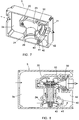
- Figures 5 and 6 show a second embodiment of a half-casing 3 in which the base of each half-casing 20 is connected to the structure 29 by a transverse wall 40.
- This wall 40 lies on the side of the half-casing 3 on which is located the structure 30 for mounting the tube 16 and is connected to the back wall 3a of this half-casing 3; it has a "C" profile and, after assembly of the half-casings 3, delimits with these back walls 3a a chamber 41 for capturing the gas aspirated via the opening 24.
- the walls 40 of the two half-casings 3 define, after assembly, with the half-casings 20, the walls 3a and the structures 30, a chamber 42 for evacuation of the hot cooling gas.
- This chamber 42 communicates via an opening 43 with the area delimited internally by the structure 29 and opens to the exterior of the half-casing 3 via an evacuation half-conduit 31.
- the conduit 31 for evacuating the hot cooling gas is integrated into the envelope of the casing formed by assembling the two half-casings 3.
- Figures 7 and 8 show a third embodiment of a half-casing 3, comprising the wall 40, the chamber 41, the chamber 42 and the opening 43 as described hereinabove.
- the chamber 42 does not open to the outside but communicates with the space 23 in which the gas for cooling the fan flows via an orifice 50.
- the hot cooling gas is recirculated in the fan scroll 7, which is suitable if the gas delivered by the apparatus 1 has a significant commercial value, in particular if that gas is oxygen (unlike the first two embodiments described, intended rather to function with air).
- This hot cooling gas is mixed, in very marginal proportions, with cool gas fed via the opening 24, although this does not impact on the degree of cooling of the motor at the gas flow rates usually employed.
- the apparatus 1 of the invention has decisive advantages over homologous apparatus of the prior art, described above.
Landscapes
- Engineering & Computer Science (AREA)
- Health & Medical Sciences (AREA)
- Mechanical Engineering (AREA)
- General Engineering & Computer Science (AREA)
- Physics & Mathematics (AREA)
- Thermal Sciences (AREA)
- Anesthesiology (AREA)
- Pulmonology (AREA)
- Emergency Medicine (AREA)
- Biomedical Technology (AREA)
- Heart & Thoracic Surgery (AREA)
- Hematology (AREA)
- Life Sciences & Earth Sciences (AREA)
- Animal Behavior & Ethology (AREA)
- General Health & Medical Sciences (AREA)
- Public Health (AREA)
- Veterinary Medicine (AREA)
- Structures Of Non-Positive Displacement Pumps (AREA)
- Respiratory Apparatuses And Protective Means (AREA)
Claims (15)
- Vorrichtung (1) für geregelte Gasabgabe, insbesondere ein Atemgerät (1), umfassend:- ein Gebläse (2), im Wesentlichen gebildet von einem Motor (5), einem Laufrad (6), das von diesem Motor (5) angetrieben wird, und einem Gebläsegehäuse (7), welches das Laufrad (6) enthält, wobei der Motor (5) in einem Motorgehäuse (8) enthalten ist, dessen erstes Ende mit dem Gebläsegehäuse (7) verbunden ist und dessen zweites Ende auf der dem Gebläsegehäuse (7) gegenüberliegenden Seite angeordnet ist; und- ein das Gebläse (2) aufnehmendes Gehäuse (22), das um dieses Gebläse (2) einen Raum (23) für Gasströmung zum Kühlen des Gebläses (2) definiert, wobei dieser Raum (23) einen Gaseinlass (24) aufweist, der an dem zweiten Ende des Motorgehäuses (8) angeordnet ist;dadurch gekennzeichnet, dass:- das erste Ende des Motorgehäuses (8) zumindest ein erstes Einlassloch (10) zum Einlassen von Kühlgas in dieses Gehäuse umfasst; und- das zweite Ende des Motorgehäuses (8) zumindest ein zweites Loch (11) zur Evakuierung des Kühlgases aus diesem Gehäuse umfasst, wobei das zweite Loch oder die Löcher (11) von dem Einlass (24) des Aufnahmegehäuses (22) auf eine solche Weise getrennt ist bzw. sind, dass Einfangen des heißen Kühlgases, welches das Motorgehäuse (8) über den Einlass (24) verlässt, um Eintreten von kaltem Kühlgas in den Raum (23) zu gestatten, verhindert wird.
- Vorrichtung (1) nach Anspruch 1, dadurch gekennzeichnet, dass das Kühlgas von einem Teil des Gases gebildet wird, das von der Vorrichtung abgegeben wird, wobei das erste Loch oder die Löcher (10) mit dem Innenraum des Gebläsegehäuses (7) in Verbindung steht bzw. stehen, so dass ein Teil des von der Vorrichtung (1) abgegebenen, unter Druck stehenden Gases durch das erste Loch oder die Löcher (10) dringt und dann durch das Motorgehäuse (8) und zur Außenseite dieses Motorgehäuses (8) über das zweite Loch bzw. die Löcher (11) fließt.
- Vorrichtung (1) nach Anspruch 2, dadurch gekennzeichnet, dass das erste Ende des Motorgehäuses (8) in eine Öffnung passt, die der Boden des Gebläsegehäuses (7) umfasst, so dass das erste Loch oder jedes erste Loch (10), das es umfasst, direkt in das Gebläsegehäuse (7) mündet und unmittelbar unter dem Laufrad (6) angeordnet ist.
- Vorrichtung (1) nach einem der Ansprüche 1 bis 3, dadurch gekennzeichnet, dass sie ein schalldämmendes Gehäuse (25) um das Aufnahmegehäuse (22) umfasst, das starr daran befestigt ist.
- Vorrichtung (1) nach Anspruch 4, dadurch gekennzeichnet, dass das schalldämmende Gehäuse (25) eine Leitung (31) zur direkten Evakuierung zur Außenseite des Kühlgases, welches das Motorgehäuse (8) passiert hat, umfasst.
- Vorrichtung (1) nach Anspruch 4, dadurch gekennzeichnet, dass das schalldämmende Gehäuse (25) eine Öffnung (50) oder Leitung zur Rezirkulation des Kühlgases, welches das Motorgehäuse (8) passiert hat, zu dem Gebläsegehäuse (7) umfasst.
- Vorrichtung (1) nach einem der Ansprüche 1 bis 6, dadurch gekennzeichnet, dass das Gebläse (2) einen Dichtungsteil (35) umfasst, der das zweite Loch oder die Löcher (11) von dem Einlass (24) zum Einlassen von Gas in den Raum (23) isoliert.
- Vorrichtung (1) nach Anspruch 7, dadurch gekennzeichnet, dass der Dichtungsteil (35) die Form einer Dichtungsschürze aufweist, von der ein erster schlauchförmiger Abschnitt (35a) um die Umfangswand des Motorgehäuses (8) passt, wobei das zweite Loch oder die Löcher (11) außerhalb des Bereichs angeordnet sind, an dem dieser erste schlauchförmige Abschnitt (35a) an dieser Umfangswand anliegt, insbesondere in einer transversalen Endwand, die dieses Gehäuse aufweist.
- Vorrichtung (1) nach Anspruch 4 und Anspruch 8, dadurch gekennzeichnet, dass die Dichtungsschürze einen zweiten schlauchförmigen Abschnitt (35b) umfasst, der an dem schalldämmenden Gehäuse (25) befestigt ist.
- Vorrichtung (1) nach Anspruch 9, dadurch gekennzeichnet, dass die Dichtungsschürze einen dritten schlauchförmigen Zwischenabschnitt (35c) zwischen den ersten und zweiten schlauchförmigen Abschnitten (35a, 35b) umfasst, der diese ersten und zweiten schlauchförmigen Abschnitte flexibel verbindet.
- Vorrichtung (1) nach Anspruch 10, dadurch gekennzeichnet, dass der dritte schlauchförmige Abschnitt (35c) von einer dünnen Wand geformt wird, die mit der radial inneren Wand des ersten schlauchförmigen Abschnitts (35a) und mit der radial inneren Wand des zweiten schlauchförmigen Abschnitts (35b) verbunden ist.
- Vorrichtung (1) nach einem der Ansprüche 1 bis 11, wobei ihr Gebläse (2) an dem zweiten Ende des Motorgehäuses (8) ein Lager (12) umfasst, das die Welle des Motors (5) führt, dadurch gekennzeichnet, dass das Motorgehäuse (8) eine Abdeckwand (15) umfasst, die dieses Lager (12) vollständig abdeckt und so jede Möglichkeit eliminiert, dass Kühlgas durch dieses Lager fließt.
- Vorrichtung (1) nach Anspruch 12, wobei die Welle des Motors (5) über eine Querwand ausgestreckt ist, die das zweite Ende des Motorgehäuses (8) aufweist, insbesondere zur Aufnahme eines Ausgleichsgewichts (14), dadurch gekennzeichnet, dass die Abdeckwand von einer Kappe (15) geformt wird, die auf dieser Querwand angebracht ist und den gesamten Abschnitt der Welle des Motors (5) abdeckt, der sich über die Querwand und das Lager hinaus erstreckt.
- Vorrichtung (1) nach einem der Ansprüche 1 bis 13, wobei das Gebläsegehäuse (7) ein Druckgas-Auslassrohr (16) umfasst, dadurch gekennzeichnet, dass es einen Dichtungsteil (36) umfasst, wobei ein erster schlauchförmiger Abschnitt davon um das Rohr (16) angeordnet ist, wobei ein zweiter schlauchförmiger Abschnitt davon in einem schalldämmenden Gehäuse (25) angeordnet ist, welches das Aufnahmegehäuse (22) enthält, und wobei ein dritter schlauchförmiger Zwischenabschnitt zwischen den ersten und zweiten schlauchförmigen Abschnitten mit den ersten und zweiten schlauchförmigen Abschnitten verbunden ist.
- Vorrichtung (1) nach einem der Ansprüche 1 bis 14, dadurch gekennzeichnet, dass das Gehäuse (22), welches das Gebläse (2) aufnimmt, eine Form aufweist, welche die Form des Motorgehäuses (8) und die Form des Gebläsegehäuses (7) unterstützt, so dass die Wand dieses Aufnahmegehäuses (22) in einem im Wesentlichen konstanten Abstand von der Wand dieses Motorgehäuses (8) und der Wand dieses Gebläsegehäuses (7) angeordnet ist.
Applications Claiming Priority (3)
| Application Number | Priority Date | Filing Date | Title |
|---|---|---|---|
| FR1153124A FR2973846B1 (fr) | 2011-04-11 | 2011-04-11 | Appareil de delivrance regulee d'un gaz, notamment appareil d'assistance respiratoire |
| US201161481454P | 2011-05-02 | 2011-05-02 | |
| PCT/EP2012/000807 WO2012139681A1 (en) | 2011-04-11 | 2012-02-24 | Apparatus for regulated delivery of a gas, notably respiratory assistance apparatus |
Publications (2)
| Publication Number | Publication Date |
|---|---|
| EP2707603A1 EP2707603A1 (de) | 2014-03-19 |
| EP2707603B1 true EP2707603B1 (de) | 2016-04-20 |
Family
ID=44119899
Family Applications (1)
| Application Number | Title | Priority Date | Filing Date |
|---|---|---|---|
| EP12710655.7A Active EP2707603B1 (de) | 2011-04-11 | 2012-02-24 | Vorrichtung für geregelte gasabgabe, im besonderen für ein atemgerät |
Country Status (5)
| Country | Link |
|---|---|
| US (1) | US9616188B2 (de) |
| EP (1) | EP2707603B1 (de) |
| CN (1) | CN103492723B (de) |
| FR (1) | FR2973846B1 (de) |
| WO (1) | WO2012139681A1 (de) |
Families Citing this family (32)
| Publication number | Priority date | Publication date | Assignee | Title |
|---|---|---|---|---|
| FR3001155B1 (fr) * | 2013-01-22 | 2015-12-25 | Air Liquide Medical Systems | Appareil d'assistance respiratoire avec turbine insonorisee |
| FR3014320B1 (fr) * | 2013-12-10 | 2017-08-25 | Air Liquide Medical Systems | Appareil d’assistance respiratoire a turbine motorisee et butees |
| FR3016294B1 (fr) * | 2014-01-14 | 2019-08-02 | Airfan | Procede d'optimisation thermique et phonique d'un moteur de production regule de gaz et appareil d'assistance respiratoire correspondant |
| FR3016795A1 (fr) * | 2014-01-29 | 2015-07-31 | Air Liquide Medical Systems | Appareil d'assistance respiratoire avec micro-soufflante a roue double |
| JP6480598B2 (ja) | 2015-04-02 | 2019-03-13 | ヒル−ロム サービシーズ プライヴェート リミテッド | 呼吸装置用マニホールド |
| FR3034819B1 (fr) | 2015-04-13 | 2017-04-28 | Air Liquide Medical Systems | Micro-soufflante pour appareil d’assistance respiratoire a refroidissement ameliore |
| FR3036143B1 (fr) | 2015-05-12 | 2019-07-05 | Air Liquide Medical Systems | Micro-soufflante a etancheite d'axe-moteur amelioree pour appareil d'assistance respiratoire |
| GB2600579B (en) * | 2015-06-24 | 2022-11-02 | Fisher & Paykel Healthcare Ltd | Breathing assistance apparatus |
| NZ773777A (en) | 2015-07-07 | 2023-12-22 | ResMed Pty Ltd | Respiratory pressure therapy device |
| WO2017039497A1 (en) | 2015-08-31 | 2017-03-09 | Maquet Critical Care Ab | Fan-driven respiratory assistance apparatus with reversed fan-motor assembly |
| DE202015009563U1 (de) * | 2015-09-24 | 2018-04-25 | Ebm-Papst St. Georgen Gmbh & Co. Kg | Lüftereinheit |
| FR3057464B1 (fr) * | 2016-10-19 | 2022-07-22 | Airfan | Appareil d'assistance respiratoire a systeme de refroidissement integre |
| JP6801774B2 (ja) * | 2017-03-21 | 2020-12-16 | 株式会社村田製作所 | 送風装置、流体制御装置 |
| FR3073421B1 (fr) * | 2017-11-10 | 2019-10-11 | Air Liquide Medical Systems | Appareil d’assistance respiratoire a micro-soufflante motorisee |
| FR3073420B1 (fr) * | 2017-11-10 | 2019-10-11 | Air Liquide Medical Systems | Appareil d'assistance respiratoire a circuit de gaz ameliore |
| CN112704788B (zh) * | 2018-10-26 | 2024-02-13 | 北京怡和嘉业医疗科技股份有限公司 | 加湿组件和呼吸通气设备 |
| WO2020121255A1 (en) | 2018-12-13 | 2020-06-18 | ResMed Pty Ltd | Pneumatic block for respiratory pressure therapy device |
| CN110145479A (zh) * | 2019-05-23 | 2019-08-20 | 大连海事大学 | 一种自带电机转子冷却系统的电动空压机 |
| FR3098121A1 (fr) | 2019-07-05 | 2021-01-08 | Air Liquide Medical Systems | Ventilateur médical avec micro-soufflante motorisée à refroidissement amélioré |
| FR3098122B1 (fr) | 2019-07-05 | 2021-06-04 | Air Liquide Medical Systems | Ventilateur médical à caisson interne incluant une micro-soufflante motorisée et des circuits de gaz |
| FR3100441A1 (fr) | 2019-09-11 | 2021-03-12 | Air Liquide Medical Systems | Ventilateur médical protégé par une structure-exosquelette |
| KR102712950B1 (ko) * | 2019-10-10 | 2024-10-08 | 한온시스템 주식회사 | 차량용 공기 압축기 |
| US11668319B2 (en) * | 2020-06-29 | 2023-06-06 | Speed to Market LTD. | Blower unit |
| FR3115465B1 (fr) | 2020-10-23 | 2025-10-10 | Eove | Système de contrôle de la micro-soufflante motorisée d’un appareil d’assistance respiratoire |
| US12290636B2 (en) | 2021-06-16 | 2025-05-06 | Northman Ip Holdco Limited | Respiratory devices |
| TW202405311A (zh) * | 2022-06-03 | 2024-02-01 | 美商博隆能源股份有限公司 | 具有罩式混流葉輪以加強冷卻之離心式鼓風機 |
| US20240426305A1 (en) * | 2023-06-23 | 2024-12-26 | Garrett Transportation I Inc. | Centrifugal-type electric refrigerant compressor having integral orifice-regulated bearing cooling arrangement |
| FR3150552A1 (fr) | 2023-06-28 | 2025-01-03 | Air Liquide Medical Systems | Roue à ailettes légère pour soufflante motorisée pour ventilateur médical |
| US20250188917A1 (en) * | 2023-12-07 | 2025-06-12 | Hill-Rom Services Pte.Ltd. | Compressor suspension system for portable gas source |
| DE102024105742A1 (de) * | 2024-02-29 | 2025-09-04 | Weinmann Emergency Medical Technology Gmbh + Co. Kg | Beatmungsgerät mit Kühlvorrichtung |
| US12434025B1 (en) * | 2024-07-26 | 2025-10-07 | Wallenberg Union Llc | Respiratory device with a containment chamber |
| US20250357819A1 (en) * | 2025-04-25 | 2025-11-20 | Dongguan Chi Drive Motors Co.,Ltd | High-efficiency and high-speed vacuum cleaner motor |
Family Cites Families (17)
| Publication number | Priority date | Publication date | Assignee | Title |
|---|---|---|---|---|
| US2272985A (en) * | 1939-10-14 | 1942-02-10 | Spencer Turbine Co | Motor mounting for vacuum cleaners |
| US2294586A (en) * | 1941-08-04 | 1942-09-01 | Del Conveyor & Mfg Company | Axial flow fan structure |
| US3026808A (en) * | 1960-02-18 | 1962-03-27 | Immovilli Silvio | Electrically operated pump assembly |
| DE2244275C3 (de) * | 1972-09-09 | 1975-09-04 | Frankl & Kirchner, Fabrik Fuer Elektromotoren U. Elektrische Apparate, 6830 Schwetzingen | Gekapselter Kollektormotor für ein Pumpenaggregat |
| GB2239491B (en) * | 1989-11-28 | 1993-09-29 | Copermill Ltd | Hot gas blower |
| GB9203766D0 (en) * | 1992-02-21 | 1992-04-08 | Priorlucky Ltd | Suction cup assemblies |
| US5350281A (en) * | 1993-01-26 | 1994-09-27 | Sundstrand Corporation | Fan with secondary air passage for motor cooling |
| ATE252403T1 (de) * | 1994-10-14 | 2003-11-15 | Bird Products Corp | Ausatmungsventil |
| US5811899A (en) * | 1997-01-28 | 1998-09-22 | General Signal Corporation | Small electric motor with airflow guide structure |
| US8517012B2 (en) * | 2001-12-10 | 2013-08-27 | Resmed Limited | Multiple stage blowers and volutes therefor |
| AU2003903139A0 (en) * | 2003-06-20 | 2003-07-03 | Resmed Limited | Breathable gas apparatus with humidifier |
| EP2032857B1 (de) * | 2006-05-24 | 2011-02-23 | ResMed Motor Technologies Inc. | Kompaktes, geräuscharmes effizientes gebläse für cpap-geräte |
| FR2908482B1 (fr) * | 2006-11-13 | 2010-04-02 | Airfan | Appareil de delivrance regulee d'un gaz notamment appareil d'assistance respiratoire |
| FR2910081B1 (fr) * | 2006-12-18 | 2010-09-03 | Airfan | Appareil de delivrance regulee d'un gaz,notamment appareil d'assistance respiratoire |
| FR2910079B1 (fr) * | 2006-12-18 | 2013-06-07 | Airfan | Appareil de delivrance de gaz,notamment d'assistance respiratoire,a chambre intermediaire de collecte de fuite d'oxygene. |
| EP2165078B1 (de) * | 2007-06-25 | 2010-10-27 | Airfan | Vorrichtung für geregelte gasabgabe, im besonderen für ein atemgerät |
| US8667962B2 (en) * | 2008-01-31 | 2014-03-11 | Resmed Limited | Respiratory apparatus |
-
2011
- 2011-04-11 FR FR1153124A patent/FR2973846B1/fr not_active Expired - Fee Related
-
2012
- 2012-02-24 US US14/007,690 patent/US9616188B2/en active Active
- 2012-02-24 CN CN201280017198.3A patent/CN103492723B/zh active Active
- 2012-02-24 WO PCT/EP2012/000807 patent/WO2012139681A1/en not_active Ceased
- 2012-02-24 EP EP12710655.7A patent/EP2707603B1/de active Active
Also Published As
| Publication number | Publication date |
|---|---|
| WO2012139681A1 (en) | 2012-10-18 |
| FR2973846B1 (fr) | 2013-05-24 |
| EP2707603A1 (de) | 2014-03-19 |
| CN103492723A (zh) | 2014-01-01 |
| CN103492723B (zh) | 2017-04-26 |
| US20140014109A1 (en) | 2014-01-16 |
| FR2973846A1 (fr) | 2012-10-12 |
| US9616188B2 (en) | 2017-04-11 |
Similar Documents
| Publication | Publication Date | Title |
|---|---|---|
| US9616188B2 (en) | Apparatus for regulated delivery of a gas, notably respiratory assistance apparatus | |
| KR101799123B1 (ko) | 원심 송풍기 조립체 | |
| JP5222594B2 (ja) | エンジン駆動発電機 | |
| CN101688539B (zh) | 调节传送气体的呼吸装置 | |
| JP5250027B2 (ja) | 質量分析計の配置 | |
| EP2122180B1 (de) | Gebläse für eine vorrichtung zur regulierten zufuhr eines gases, insbesondere sauerstoff | |
| US9044559B2 (en) | Apparatus for the regulated supply of a gas, in particular an assisted breathing apparatus | |
| US6896478B2 (en) | Dual fan blower with axial expansion | |
| US20150352477A1 (en) | Mist separator | |
| RU2014110537A (ru) | Центробежный вентилятор | |
| KR101911782B1 (ko) | 연료전지 차량용 공기 블로워 | |
| CN109672293A (zh) | 具有改进的气流和噪声减小特性的电机-风扇组件 | |
| CN109217535B (zh) | 电机端盖及具有其的电机 | |
| CN101589235A (zh) | 特别是氧气的气体调节性传送用装置的风扇 | |
| JP2012505990A (ja) | 車両用ファン装置 | |
| EP1571343B1 (de) | Motor-Verdichteraggregat für Kraftfahrzeuge | |
| JP2008045551A5 (de) | ||
| KR101230113B1 (ko) | 차량용 이중 팬 환기 조립체 | |
| CN118843739A (zh) | 用于内燃机的气缸盖罩 | |
| US20220056826A1 (en) | Blow-by gas filtration assembly | |
| US20200353398A1 (en) | Filter and vacuum food processor | |
| CN115342075B (zh) | 出风装置及无叶风扇 | |
| CN114790992B (zh) | 用于电动压缩机装置的湿气排出系统 | |
| JP6181908B2 (ja) | ブロワ | |
| KR20190083523A (ko) | 오일 분리기 |
Legal Events
| Date | Code | Title | Description |
|---|---|---|---|
| PUAI | Public reference made under article 153(3) epc to a published international application that has entered the european phase |
Free format text: ORIGINAL CODE: 0009012 |
|
| 17P | Request for examination filed |
Effective date: 20131111 |
|
| AK | Designated contracting states |
Kind code of ref document: A1 Designated state(s): AL AT BE BG CH CY CZ DE DK EE ES FI FR GB GR HR HU IE IS IT LI LT LU LV MC MK MT NL NO PL PT RO RS SE SI SK SM TR |
|
| DAX | Request for extension of the european patent (deleted) | ||
| GRAP | Despatch of communication of intention to grant a patent |
Free format text: ORIGINAL CODE: EPIDOSNIGR1 |
|
| INTG | Intention to grant announced |
Effective date: 20151106 |
|
| GRAS | Grant fee paid |
Free format text: ORIGINAL CODE: EPIDOSNIGR3 |
|
| GRAA | (expected) grant |
Free format text: ORIGINAL CODE: 0009210 |
|
| AK | Designated contracting states |
Kind code of ref document: B1 Designated state(s): AL AT BE BG CH CY CZ DE DK EE ES FI FR GB GR HR HU IE IS IT LI LT LU LV MC MK MT NL NO PL PT RO RS SE SI SK SM TR |
|
| REG | Reference to a national code |
Ref country code: GB Ref legal event code: FG4D |
|
| REG | Reference to a national code |
Ref country code: CH Ref legal event code: EP |
|
| REG | Reference to a national code |
Ref country code: AT Ref legal event code: REF Ref document number: 792766 Country of ref document: AT Kind code of ref document: T Effective date: 20160515 |
|
| REG | Reference to a national code |
Ref country code: IE Ref legal event code: FG4D |
|
| REG | Reference to a national code |
Ref country code: DE Ref legal event code: R096 Ref document number: 602012017314 Country of ref document: DE |
|
| REG | Reference to a national code |
Ref country code: NL Ref legal event code: FP |
|
| REG | Reference to a national code |
Ref country code: LT Ref legal event code: MG4D |
|
| REG | Reference to a national code |
Ref country code: AT Ref legal event code: MK05 Ref document number: 792766 Country of ref document: AT Kind code of ref document: T Effective date: 20160420 |
|
| PG25 | Lapsed in a contracting state [announced via postgrant information from national office to epo] |
Ref country code: PL Free format text: LAPSE BECAUSE OF FAILURE TO SUBMIT A TRANSLATION OF THE DESCRIPTION OR TO PAY THE FEE WITHIN THE PRESCRIBED TIME-LIMIT Effective date: 20160420 Ref country code: FI Free format text: LAPSE BECAUSE OF FAILURE TO SUBMIT A TRANSLATION OF THE DESCRIPTION OR TO PAY THE FEE WITHIN THE PRESCRIBED TIME-LIMIT Effective date: 20160420 Ref country code: LT Free format text: LAPSE BECAUSE OF FAILURE TO SUBMIT A TRANSLATION OF THE DESCRIPTION OR TO PAY THE FEE WITHIN THE PRESCRIBED TIME-LIMIT Effective date: 20160420 Ref country code: NO Free format text: LAPSE BECAUSE OF FAILURE TO SUBMIT A TRANSLATION OF THE DESCRIPTION OR TO PAY THE FEE WITHIN THE PRESCRIBED TIME-LIMIT Effective date: 20160720 |
|
| PG25 | Lapsed in a contracting state [announced via postgrant information from national office to epo] |
Ref country code: SE Free format text: LAPSE BECAUSE OF FAILURE TO SUBMIT A TRANSLATION OF THE DESCRIPTION OR TO PAY THE FEE WITHIN THE PRESCRIBED TIME-LIMIT Effective date: 20160420 Ref country code: ES Free format text: LAPSE BECAUSE OF FAILURE TO SUBMIT A TRANSLATION OF THE DESCRIPTION OR TO PAY THE FEE WITHIN THE PRESCRIBED TIME-LIMIT Effective date: 20160420 Ref country code: PT Free format text: LAPSE BECAUSE OF FAILURE TO SUBMIT A TRANSLATION OF THE DESCRIPTION OR TO PAY THE FEE WITHIN THE PRESCRIBED TIME-LIMIT Effective date: 20160822 Ref country code: GR Free format text: LAPSE BECAUSE OF FAILURE TO SUBMIT A TRANSLATION OF THE DESCRIPTION OR TO PAY THE FEE WITHIN THE PRESCRIBED TIME-LIMIT Effective date: 20160721 Ref country code: LV Free format text: LAPSE BECAUSE OF FAILURE TO SUBMIT A TRANSLATION OF THE DESCRIPTION OR TO PAY THE FEE WITHIN THE PRESCRIBED TIME-LIMIT Effective date: 20160420 Ref country code: AT Free format text: LAPSE BECAUSE OF FAILURE TO SUBMIT A TRANSLATION OF THE DESCRIPTION OR TO PAY THE FEE WITHIN THE PRESCRIBED TIME-LIMIT Effective date: 20160420 Ref country code: RS Free format text: LAPSE BECAUSE OF FAILURE TO SUBMIT A TRANSLATION OF THE DESCRIPTION OR TO PAY THE FEE WITHIN THE PRESCRIBED TIME-LIMIT Effective date: 20160420 Ref country code: HR Free format text: LAPSE BECAUSE OF FAILURE TO SUBMIT A TRANSLATION OF THE DESCRIPTION OR TO PAY THE FEE WITHIN THE PRESCRIBED TIME-LIMIT Effective date: 20160420 |
|
| PG25 | Lapsed in a contracting state [announced via postgrant information from national office to epo] |
Ref country code: BE Free format text: LAPSE BECAUSE OF FAILURE TO SUBMIT A TRANSLATION OF THE DESCRIPTION OR TO PAY THE FEE WITHIN THE PRESCRIBED TIME-LIMIT Effective date: 20160420 |
|
| REG | Reference to a national code |
Ref country code: DE Ref legal event code: R097 Ref document number: 602012017314 Country of ref document: DE |
|
| PG25 | Lapsed in a contracting state [announced via postgrant information from national office to epo] |
Ref country code: DK Free format text: LAPSE BECAUSE OF FAILURE TO SUBMIT A TRANSLATION OF THE DESCRIPTION OR TO PAY THE FEE WITHIN THE PRESCRIBED TIME-LIMIT Effective date: 20160420 Ref country code: RO Free format text: LAPSE BECAUSE OF FAILURE TO SUBMIT A TRANSLATION OF THE DESCRIPTION OR TO PAY THE FEE WITHIN THE PRESCRIBED TIME-LIMIT Effective date: 20160420 Ref country code: EE Free format text: LAPSE BECAUSE OF FAILURE TO SUBMIT A TRANSLATION OF THE DESCRIPTION OR TO PAY THE FEE WITHIN THE PRESCRIBED TIME-LIMIT Effective date: 20160420 Ref country code: SK Free format text: LAPSE BECAUSE OF FAILURE TO SUBMIT A TRANSLATION OF THE DESCRIPTION OR TO PAY THE FEE WITHIN THE PRESCRIBED TIME-LIMIT Effective date: 20160420 Ref country code: CZ Free format text: LAPSE BECAUSE OF FAILURE TO SUBMIT A TRANSLATION OF THE DESCRIPTION OR TO PAY THE FEE WITHIN THE PRESCRIBED TIME-LIMIT Effective date: 20160420 |
|
| PLBE | No opposition filed within time limit |
Free format text: ORIGINAL CODE: 0009261 |
|
| REG | Reference to a national code |
Ref country code: FR Ref legal event code: PLFP Year of fee payment: 6 |
|
| STAA | Information on the status of an ep patent application or granted ep patent |
Free format text: STATUS: NO OPPOSITION FILED WITHIN TIME LIMIT |
|
| PG25 | Lapsed in a contracting state [announced via postgrant information from national office to epo] |
Ref country code: SM Free format text: LAPSE BECAUSE OF FAILURE TO SUBMIT A TRANSLATION OF THE DESCRIPTION OR TO PAY THE FEE WITHIN THE PRESCRIBED TIME-LIMIT Effective date: 20160420 |
|
| 26N | No opposition filed |
Effective date: 20170123 |
|
| PG25 | Lapsed in a contracting state [announced via postgrant information from national office to epo] |
Ref country code: SI Free format text: LAPSE BECAUSE OF FAILURE TO SUBMIT A TRANSLATION OF THE DESCRIPTION OR TO PAY THE FEE WITHIN THE PRESCRIBED TIME-LIMIT Effective date: 20160420 |
|
| PG25 | Lapsed in a contracting state [announced via postgrant information from national office to epo] |
Ref country code: MC Free format text: LAPSE BECAUSE OF FAILURE TO SUBMIT A TRANSLATION OF THE DESCRIPTION OR TO PAY THE FEE WITHIN THE PRESCRIBED TIME-LIMIT Effective date: 20160420 |
|
| REG | Reference to a national code |
Ref country code: IE Ref legal event code: MM4A |
|
| PG25 | Lapsed in a contracting state [announced via postgrant information from national office to epo] |
Ref country code: LU Free format text: LAPSE BECAUSE OF NON-PAYMENT OF DUE FEES Effective date: 20170224 |
|
| REG | Reference to a national code |
Ref country code: FR Ref legal event code: PLFP Year of fee payment: 7 |
|
| PG25 | Lapsed in a contracting state [announced via postgrant information from national office to epo] |
Ref country code: IE Free format text: LAPSE BECAUSE OF NON-PAYMENT OF DUE FEES Effective date: 20170224 |
|
| PG25 | Lapsed in a contracting state [announced via postgrant information from national office to epo] |
Ref country code: MT Free format text: LAPSE BECAUSE OF NON-PAYMENT OF DUE FEES Effective date: 20170224 |
|
| PG25 | Lapsed in a contracting state [announced via postgrant information from national office to epo] |
Ref country code: AL Free format text: LAPSE BECAUSE OF FAILURE TO SUBMIT A TRANSLATION OF THE DESCRIPTION OR TO PAY THE FEE WITHIN THE PRESCRIBED TIME-LIMIT Effective date: 20160420 |
|
| PG25 | Lapsed in a contracting state [announced via postgrant information from national office to epo] |
Ref country code: HU Free format text: LAPSE BECAUSE OF FAILURE TO SUBMIT A TRANSLATION OF THE DESCRIPTION OR TO PAY THE FEE WITHIN THE PRESCRIBED TIME-LIMIT; INVALID AB INITIO Effective date: 20120224 |
|
| PG25 | Lapsed in a contracting state [announced via postgrant information from national office to epo] |
Ref country code: BG Free format text: LAPSE BECAUSE OF FAILURE TO SUBMIT A TRANSLATION OF THE DESCRIPTION OR TO PAY THE FEE WITHIN THE PRESCRIBED TIME-LIMIT Effective date: 20160420 |
|
| PG25 | Lapsed in a contracting state [announced via postgrant information from national office to epo] |
Ref country code: CY Free format text: LAPSE BECAUSE OF NON-PAYMENT OF DUE FEES Effective date: 20160420 |
|
| PG25 | Lapsed in a contracting state [announced via postgrant information from national office to epo] |
Ref country code: MK Free format text: LAPSE BECAUSE OF FAILURE TO SUBMIT A TRANSLATION OF THE DESCRIPTION OR TO PAY THE FEE WITHIN THE PRESCRIBED TIME-LIMIT Effective date: 20160420 |
|
| PG25 | Lapsed in a contracting state [announced via postgrant information from national office to epo] |
Ref country code: TR Free format text: LAPSE BECAUSE OF FAILURE TO SUBMIT A TRANSLATION OF THE DESCRIPTION OR TO PAY THE FEE WITHIN THE PRESCRIBED TIME-LIMIT Effective date: 20160420 |
|
| PG25 | Lapsed in a contracting state [announced via postgrant information from national office to epo] |
Ref country code: IS Free format text: LAPSE BECAUSE OF FAILURE TO SUBMIT A TRANSLATION OF THE DESCRIPTION OR TO PAY THE FEE WITHIN THE PRESCRIBED TIME-LIMIT Effective date: 20160820 |
|
| PGFP | Annual fee paid to national office [announced via postgrant information from national office to epo] |
Ref country code: NL Payment date: 20260127 Year of fee payment: 15 |
|
| REG | Reference to a national code |
Ref country code: CH Ref legal event code: U11 Free format text: ST27 STATUS EVENT CODE: U-0-0-U10-U11 (AS PROVIDED BY THE NATIONAL OFFICE) Effective date: 20260301 |
|
| PGFP | Annual fee paid to national office [announced via postgrant information from national office to epo] |
Ref country code: GB Payment date: 20260225 Year of fee payment: 15 |
|
| PGFP | Annual fee paid to national office [announced via postgrant information from national office to epo] |
Ref country code: DE Payment date: 20260206 Year of fee payment: 15 |
|
| PGFP | Annual fee paid to national office [announced via postgrant information from national office to epo] |
Ref country code: IT Payment date: 20260210 Year of fee payment: 15 |
|
| PGFP | Annual fee paid to national office [announced via postgrant information from national office to epo] |
Ref country code: FR Payment date: 20260223 Year of fee payment: 15 |
|
| PGFP | Annual fee paid to national office [announced via postgrant information from national office to epo] |
Ref country code: CH Payment date: 20260301 Year of fee payment: 15 |