EP2708100B1 - Appareil électronique flexible - Google Patents
Appareil électronique flexible Download PDFInfo
- Publication number
- EP2708100B1 EP2708100B1 EP12782245.0A EP12782245A EP2708100B1 EP 2708100 B1 EP2708100 B1 EP 2708100B1 EP 12782245 A EP12782245 A EP 12782245A EP 2708100 B1 EP2708100 B1 EP 2708100B1
- Authority
- EP
- European Patent Office
- Prior art keywords
- flexible layer
- adjustment member
- configuration
- flexible
- layer
- Prior art date
- Legal status (The legal status is an assumption and is not a legal conclusion. Google has not performed a legal analysis and makes no representation as to the accuracy of the status listed.)
- Active
Links
Images




Classifications
-
- G—PHYSICS
- G06—COMPUTING OR CALCULATING; COUNTING
- G06F—ELECTRIC DIGITAL DATA PROCESSING
- G06F1/00—Details not covered by groups G06F3/00 - G06F13/00 and G06F21/00
- G06F1/16—Constructional details or arrangements
- G06F1/1613—Constructional details or arrangements for portable computers
- G06F1/1633—Constructional details or arrangements of portable computers not specific to the type of enclosures covered by groups G06F1/1615 - G06F1/1626
- G06F1/1637—Details related to the display arrangement, including those related to the mounting of the display in the housing
- G06F1/1652—Details related to the display arrangement, including those related to the mounting of the display in the housing the display being flexible, e.g. mimicking a sheet of paper, or rollable
-
- G—PHYSICS
- G06—COMPUTING OR CALCULATING; COUNTING
- G06F—ELECTRIC DIGITAL DATA PROCESSING
- G06F1/00—Details not covered by groups G06F3/00 - G06F13/00 and G06F21/00
- G06F1/16—Constructional details or arrangements
- G06F1/1613—Constructional details or arrangements for portable computers
- G06F1/1626—Constructional details or arrangements for portable computers with a single-body enclosure integrating a flat display, e.g. Personal Digital Assistants [PDAs]
-
- G—PHYSICS
- G06—COMPUTING OR CALCULATING; COUNTING
- G06F—ELECTRIC DIGITAL DATA PROCESSING
- G06F1/00—Details not covered by groups G06F3/00 - G06F13/00 and G06F21/00
- G06F1/16—Constructional details or arrangements
- G06F1/1613—Constructional details or arrangements for portable computers
- G06F1/1633—Constructional details or arrangements of portable computers not specific to the type of enclosures covered by groups G06F1/1615 - G06F1/1626
- G06F1/1675—Miscellaneous details related to the relative movement between the different enclosures or enclosure parts
-
- G—PHYSICS
- G06—COMPUTING OR CALCULATING; COUNTING
- G06F—ELECTRIC DIGITAL DATA PROCESSING
- G06F1/00—Details not covered by groups G06F3/00 - G06F13/00 and G06F21/00
- G06F1/16—Constructional details or arrangements
- G06F1/1613—Constructional details or arrangements for portable computers
- G06F1/1633—Constructional details or arrangements of portable computers not specific to the type of enclosures covered by groups G06F1/1615 - G06F1/1626
- G06F1/1675—Miscellaneous details related to the relative movement between the different enclosures or enclosure parts
- G06F1/1677—Miscellaneous details related to the relative movement between the different enclosures or enclosure parts for detecting open or closed state or particular intermediate positions assumed by movable parts of the enclosure, e.g. detection of display lid position with respect to main body in a laptop, detection of opening of the cover of battery compartment
-
- G—PHYSICS
- G09—EDUCATION; CRYPTOGRAPHY; DISPLAY; ADVERTISING; SEALS
- G09F—DISPLAYING; ADVERTISING; SIGNS; LABELS OR NAME-PLATES; SEALS
- G09F9/00—Indicating arrangements for variable information in which the information is built-up on a support by selection or combination of individual elements
- G09F9/30—Indicating arrangements for variable information in which the information is built-up on a support by selection or combination of individual elements in which the desired character or characters are formed by combining individual elements
- G09F9/301—Indicating arrangements for variable information in which the information is built-up on a support by selection or combination of individual elements in which the desired character or characters are formed by combining individual elements flexible foldable or roll-able electronic displays, e.g. thin LCD, OLED
-
- H—ELECTRICITY
- H04—ELECTRIC COMMUNICATION TECHNIQUE
- H04M—TELEPHONIC COMMUNICATION
- H04M1/00—Substation equipment, e.g. for use by subscribers
- H04M1/02—Constructional features of telephone sets
- H04M1/0202—Portable telephone sets, e.g. cordless phones, mobile phones or bar type handsets
- H04M1/026—Details of the structure or mounting of specific components
- H04M1/0266—Details of the structure or mounting of specific components for a display module assembly
-
- Y—GENERAL TAGGING OF NEW TECHNOLOGICAL DEVELOPMENTS; GENERAL TAGGING OF CROSS-SECTIONAL TECHNOLOGIES SPANNING OVER SEVERAL SECTIONS OF THE IPC; TECHNICAL SUBJECTS COVERED BY FORMER USPC CROSS-REFERENCE ART COLLECTIONS [XRACs] AND DIGESTS
- Y10—TECHNICAL SUBJECTS COVERED BY FORMER USPC
- Y10T—TECHNICAL SUBJECTS COVERED BY FORMER US CLASSIFICATION
- Y10T428/00—Stock material or miscellaneous articles
- Y10T428/24—Structurally defined web or sheet [e.g., overall dimension, etc.]
- Y10T428/24025—Superposed movable attached layers or components
-
- Y—GENERAL TAGGING OF NEW TECHNOLOGICAL DEVELOPMENTS; GENERAL TAGGING OF CROSS-SECTIONAL TECHNOLOGIES SPANNING OVER SEVERAL SECTIONS OF THE IPC; TECHNICAL SUBJECTS COVERED BY FORMER USPC CROSS-REFERENCE ART COLLECTIONS [XRACs] AND DIGESTS
- Y10—TECHNICAL SUBJECTS COVERED BY FORMER USPC
- Y10T—TECHNICAL SUBJECTS COVERED BY FORMER US CLASSIFICATION
- Y10T428/00—Stock material or miscellaneous articles
- Y10T428/249921—Web or sheet containing structurally defined element or component
- Y10T428/249923—Including interlaminar mechanical fastener
-
- Y—GENERAL TAGGING OF NEW TECHNOLOGICAL DEVELOPMENTS; GENERAL TAGGING OF CROSS-SECTIONAL TECHNOLOGIES SPANNING OVER SEVERAL SECTIONS OF THE IPC; TECHNICAL SUBJECTS COVERED BY FORMER USPC CROSS-REFERENCE ART COLLECTIONS [XRACs] AND DIGESTS
- Y10—TECHNICAL SUBJECTS COVERED BY FORMER USPC
- Y10T—TECHNICAL SUBJECTS COVERED BY FORMER US CLASSIFICATION
- Y10T428/00—Stock material or miscellaneous articles
- Y10T428/249921—Web or sheet containing structurally defined element or component
- Y10T428/249953—Composite having voids in a component [e.g., porous, cellular, etc.]
- Y10T428/24996—With internal element bridging layers, nonplanar interface between layers, or intermediate layer of commingled adjacent foam layers
Definitions
- the present application relates generally to a flexible electronic apparatus.
- an apparatus with adjustable flexibility there is provided an apparatus with adjustable flexibility.
- the apparatus can be used in a first configuration and a second configuration.
- the apparatus In the first configuration the apparatus is flexible and in the second configuration the apparatus is rigid or the flexibility is at least restricted.
- an apparatus that comprises a first flexible layer and at least one adjustment member attached to the first flexible layer.
- the adjustment member is movable between a first configuration and a second configuration. In the first configuration, the adjustment member is configured to allow flexibility of the apparatus, and in the second configuration, the adjustment member is configured to restrict flexibility of the apparatus.
- the adjustment member in the second configuration, is configured to make at least one dimension of the first flexible layer rigid.
- the apparatus further comprises a second flexible layer and the adjustment member resides between the first flexible layer and the second flexible layer.
- the first flexible layer and the second flexible layer are at least partially connected to each other with an elastic connection.
- the apparatus comprises more than one adjustment members.
- the adjustment member is configured to bend at least one of the first and the second flexible layers in the second configuration.
- the adjustment member is configured to adjust distance between the first flexible layer and the second flexible layer.
- the adjustment member is configured to adjust distance between the first flexible layer and the second flexible layer so that the distance between the first flexible layer and the second flexible layer is larger in the second configuration than in the first configuration.
- components or layers of the apparatus are flexible. In another example embodiment, all components need not be fully flexible. In an embodiment at least one of the components of the apparatus is constructed from small rigid pieces that are connected to each other to form a flexible structure. In an embodiment the rigid parts are connected to each other with elastic material. For example battery can be constructed in this way.
- Fig. 1A shows an apparatus 101 according to an embodiment of the invention.
- the apparatus 101 can be for example a mobile phone or some other end user electronic device.
- the apparatus 101 comprises a display element 102.
- the display 102 shows items 103-105.
- the apparatus 101 is shown in a first configuration, wherein the apparatus 101 is flexible. The flexible configuration allows that the apparatus 101 has been bent to form an arc.
- Fig. 1B shows the apparatus 101 of Figure 1A in a second configuration, wherein the apparatus 101 is rigid.
- the rigid configuration prevents the apparatus from being bent the same way as in the flexible configuration.
- Fig. 2A shows an apparatus according to an embodiment of the invention in a first configuration.
- the apparatus can be the apparatus 101 of Figures 1A and 1B or some other apparatus.
- the apparatus comprises a first flexible layer 201 and a second flexible layer 202 and an adjustment member 203 between the layers 201 and 202.
- Elastic connections 206 and 207 attach the first 201 and the second 202 layers to each other at two opposite edges of the apparatus.
- elastomers can be used for providing the elastic connection.
- the elastic connection comprises electronic connections formed by means of conductive elastomers or flexible wiring.
- the first layer 201 is a display layer and the second layer 202 is a back layer.
- the adjustment member 203 is an adjustment bar. In the shown first configuration the adjustment bar 203 is flat between the first 201 and the second 202 layers. The first 201 and the second 202 layers are close to each other. The small distance between the first 201 and the second 202 layers allows flexibility of the apparatus whereby the apparatus can be bent.
- Fig. 2B shows a side view of the apparatus of Figure 2A .
- the adjustment member 203 is turnable around axle 204.
- the adjustment member 203 has a rectangular profile.
- Fig. 2C shows the apparatus of Figure 2A in a second configuration.
- the adjustment member 203 has been turned 90 degrees so that distance between the first 201 and the second 202 layers increases and the apparatus structure bloats.
- the bloated structure makes the apparatus rigid and non-bendable or at least restricts flexibility of the apparatus.
- Fig. 2D shows a side view of the apparatus of Figure 2C . Therein it is shown that the adjustment member 203 has been turned 90 degrees around the axle 204 from the position shown in Figure 2B .
- adjustment member 203 instead of rectangular form of adjustment member 203 also other forms may be used. Some examples are shown in Figure 3A-3C .
- the adjustment member in Figures 3A-3C may be an adjustment bar or an adjustment snippet, for example. It must be noted that the adjustment bar does not need to have equal length compared to the apparatus length. In an example embodiment the adjustment bar is shorter than the apparatus and in another example embodiment the adjustment bar comprises several shorter bars.
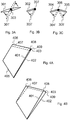
- Fig. 3A shows a side view of an adjustment member 301 according to an embodiment of the invention.
- the adjustment member 301 comprises curved edges.
- the adjustment member 301 is turnable around axle 303 into other positions 301'.
- Fig. 3B shows a side view of an adjustment member 302 according to another embodiment of the invention.
- the adjustment member 302 is turnable around axle 307 into other positions 302'. That is, the turning axle 307 is not in the middle of the adjustment member, but in one end of the adjustment member.
- the adjustment member 302 is attached to a flexible layer of an apparatus with a hinge from the turning axle 307.
- Fig. 3C shows a side view an adjustment member according to yet another embodiment of the invention.
- the adjustment member comprises two parts 304 and 305 that are foldable around axle 306 into other positions 304' and 305'.
- Fig. 4A shows an apparatus according to an embodiment of the invention in a first configuration.
- the apparatus can be the apparatus 101 of Figures 1A and 1B or some other apparatus.
- the apparatus comprises a first flexible layer 401 and a second flexible layer 402.
- Elastic connection 405 attaches the 401 and the second 402 layers to each other at one edge of the apparatus.
- the opposite edge of the apparatus comprises an adjustment member 403 between the first 401 and the second 402 layers.
- the adjustment member 403 is an adjustment bar.
- the adjustment member 403 is attached to the first 401 or the second 402 layer with a hinge. In the shown first configuration the adjustment bar 403 is flat between the first 401 and the second 402 layers and the apparatus is flexible.
- Fig. 4B shows the apparatus of Figure 4A in a second configuration.
- the adjustment member 403 has been turned so that the apparatus becomes rigid or at least flexibility of the apparatus is restricted.
- the apparatus of Figures 4A and 4B comprises sliding grips that are configured to prevent the first 401 and the second 402 layers from slipping away from each other.
- the apparatus of Figures 4A and 4B comprises elastic connections between corners 406 and 407 as well as corners 408 and 409.
- the elastic connections are made of some suitable rubber-like material, e.g. elastic band may be used. The elastic connections cause a pulling force that pulls the first 401 and the second 402 layers towards each other thereby preventing the first 401 and the second 402 layers from slipping away from each other.
- a technical effect of the embodiment of Figures 4A and 4B is that if the apparatus surface comprises a display, in the rigid configuration the display is in a suitable viewing angle (slightly tilted) when the apparatus is placed on a table.
- an adjustment bar like the adjustment bar 403 of Figures 4A and 4B could be placed on two opposite sides of the apparatus. In that case the elastic connection 405 between the layers would not be necessary. In this embodiment it is possible that the flexible layers may become slightly misaligned in the flexible (first) configuration, but the layers would be again aligned when the apparatus is set to the rigid (second) configuration.
- the adjustment member is an adjustment snippet. Such embodiment is discussed in the following.
- Fig. 5A shows an apparatus according to an embodiment of the invention in a first configuration.
- the apparatus can be the apparatus 101 of Figures 1A and 1B or some other apparatus.
- the apparatus comprises a first flexible layer 501 and a second flexible layer 502 and adjustment members 503 and 504 between the layers 501 and 502.
- Elastic connections 506 and 507 attach the first 501 and the second 502 layers to each other at two opposite edges of the apparatus.
- the adjustment members 503 and 504 are snippets of suitable material.
- the adjustment members 503 and 504 are attached to the first 501 or the second 502 layer with hinges. In the shown first configuration the adjustment snippets 503 and 504 are flat between the first 501 and the second 502 layers and the apparatus is flexible.
- Fig. 5B shows the apparatus of Figure 5A in a second configuration.
- the adjustment members 503 and 504 have been turned so that the apparatus becomes rigid or at least flexibility of the apparatus is restricted.
- the adjustment member is a pressure bag. Such embodiment is discussed in the following.
- Fig. 6A shows an apparatus according to an embodiment of the invention in a first configuration.
- the apparatus can be the apparatus 101 of Figures 1A and 1B or some other apparatus.
- the apparatus comprises a first flexible layer 601 and a second flexible layer 602 and an adjustment member 603 between the layers 601 and 602.
- Elastic connections 606 and 607 attach the first 601 and the second 602 layers to each other at two opposite edges of the apparatus.
- the adjustment member 603 is a pressure bag.
- the pressure bag 603 is attached to the first 601 and/or the second 602 layer. In the shown first configuration the pressure bag 603 is flat (empty, no pressure) between the first 601 and the second 602 layers and the apparatus is flexible.
- Fig. 6B shows the apparatus of Figure 6A in a second configuration.
- the pressure bag 603 has been bloated with pressure so that the apparatus becomes rigid or at least flexibility of the apparatus is restricted.
- the adjustment member is configured to restrict or allow movement of the first flexible layer in relation to the second flexible layer.
- the adjustment member in the first configuration, is configured to allow movement of the second flexible layer in relation to the first flexible layer, and in the second configuration, the adjustment member is configured to restrict movement of the second flexible layer in relation to the first flexible layer.
- the apparatus comprises elastic seaming between the first flexible layer and the second flexible layer, and in the first configuration, the adjustment member is configured to allow sideways or parallel movement between the first flexible layer and the second flexible layer, and in the second configuration, the adjustment member is configured to attach the first flexible layer and the second flexible layer to each other so that sideways or parallel movement between the first flexible layer and the second flexible layer is not allowed.
- the adjustment member is configured to allow sideways or parallel movement between the first flexible layer and the second flexible layer, and in the second configuration, the adjustment member is configured to attach the first flexible layer and the second flexible layer to each other so that sideways or parallel movement between the first flexible layer and the second flexible layer is not allowed.
- Fig. 7A shows an apparatus according to an embodiment of the invention in a first configuration.
- the apparatus can be the apparatus 101 of Figures 1A and 1B or some other apparatus.
- the apparatus comprises a first flexible layer 701 and a second flexible layer 702 and an elastic seaming 705 that connects the layers 701 and 702 to each other.
- the distance between the layers 701 and 702 is fixed.
- the distance between the layers 701 and 702 is relatively large, for example 5 mm.
- the apparatus comprises adjustment members 703 and 704 between the layers 701 and 702.
- the adjustment members 703 and 704 are attached to the first layer 701. In the first configuration the first layer 701 and the adjustment members 703 and 704 are configured to freely slide relative to the second layer 702. Thereby the apparatus is flexible.
- Fig. 7B shows the apparatus of Figure 7A in a second configuration.
- the adjustment members 703 and 704 are configured to forbid movement of the first layer 701 in relation to the second layer 702 thereby making the apparatus structure rigid or at least restricting flexibility of the apparatus.
- Fig. 7C shows an enlarged detail of apparatus of Figure 7A .
- the adjustment member 704 is firmly attached to the first layer 701 with a connection 707.
- the other end 708 of the adjustment member 704 is free and can freely slide relative to the second layer 702.
- Fig. 7D shows an enlarged detail of apparatus of Figure 7B .
- the adjustment member 704 is attached to the second layer 702 with a connection 709 thereby restricting movement of the layers 701 and 702 relative to each other and thus flexibility of the apparatus.
- the adjustment member 704 is a gripping mechanism that can be attached to the second layer 702.
- the adjustment member 704 is a hook that can be attached to the second layer 702.
- the adjustment member 704 comprises a moving or sliding part that can be slid to a position in which it prevents movement of the second layer 702 in relation to the first layer 701.
- the sliding part prevents the second layer 702 from sliding outwards in relation to the first layer 701.
- the structure of the apparatus of Figures 7A-7D is such that it is possible to bend the apparatus in opposite directions, e.g. upwards and downwards.
- the structure is two-sided.
- the apparatus is bendable in opposite directions relative to the same axle.
- two flexible layers of an apparatus are bind together from all edges of the layers with an elastic connection.
- the apparatus comprises an adjustment member configured to stay flat in the flexible (first) configuration and to bloat the center of the apparatus in a rigid (second) configuration.
- One of the adjustment members discussed above in connection to other embodiments may be used in this connection.
- Fig. 8 shows an apparatus according to an embodiment of the invention in a second configuration.
- the apparatus can be the apparatus 101 of Figures 1A and 1B or some other apparatus.
- the apparatus comprises a first flexible layer 801 and an adjustment member 804 behind the layer 801.
- the adjustment member 804 is positioned such that it bends the first layer 801 to make the apparatus rigid or at least to restrict flexibility of the apparatus.
- the adjustment member is a bendable strip or ribbon. I.e. the adjustment member is bent to bend the flexible layer(s) thereby making the flexible layer(s) rigid.
- Such bendable adjustment member may be a metal strip or ribbon.
- the bendable strip bends in response to electric currency being applied to the strip. Such effect may be based on heat expansion.
- a metal strip that expands and becomes longer in response to electric currency being applied to it is attached to a flexible layer of an apparatus. The flexible layer is such that it does not expand and thereby the flexible layer bends as the metal strip expands and the apparatus becomes rigid or at least flexibility of the apparatus is restricted.
- a piezoelectric element is used as the adjustment member for providing a similar effect.
- Fig. 9A shows an apparatus according to an embodiment of the invention in a first configuration.
- the apparatus can be the apparatus 101 of Figures 1A and 1B or some other apparatus
- the apparatus comprises a first flexible layer 901 and adjustment members 903 and 904 behind the layer 901.
- the adjustment members 903 and 904 are flat behind the layer 901 and the apparatus is flexible.
- the adjustment members 903 and 904 are arranged perpendicularly in relation to one another so that rigidity in two dimensions can be provided.
- Fig. 9B shows the apparatus of Figure 9A in a second configuration.
- the adjustment members 903 and 904 have been turned 90 degrees so that the apparatus becomes rigid or at least has restricted flexibility.
- the adjustment members 903 and 904 bend the first layer 901 to make it rigid.
- the first layer is not necessarily bent, but the perpendicular positioning of the adjustment members 903 and 904 makes the apparatus rigid or at least restricts flexibility of the apparatus.
- a technical effect that may be achieved with this structure is that rigidity in two directions can be provided.
- flexibility of the apparatus is manually controllable.
- a technical effect of such embodiment is that the user can make the decision to use the apparatus in flexible/rigid configuration irrespective of the operating mode of the apparatus.
- the adjustment member is manually controllable/movable.
- there is a manual handle that is operable by a user of the apparatus.
- the adjustment member is moved using an electro mechanic component, such as a servo motor.
- flexibility of the apparatus is automatically controlled responsive to operating mode of the apparatus.
- the apparatus is set to flexible configuration in a transport mode and to rigid configuration in use mode (e.g. photography, picture browsing, message typing etc).
- the apparatus is set to flexible configuration in a game mode. This suits for example games or other applications that are controlled by bending the apparatus.
- Fig. 10 shows a rough flow diagram showing a method in accordance with an embodiment of the invention.
- phase 1001 operating mode of the apparatus is observed.
- phase 1002 a first operating mode is detected and responsive to that a flexible configuration is taken into use in phase 1004.
- phase 1003 a second operating mode is detected and responsive to that a rigid configuration is taken into use in phase 1005. From phases 1004 and 1005 the process return to phase 1001.
- Fig. 11 shows a block diagram of an apparatus 1101 according to an embodiment of the invention.
- the apparatus is for example the apparatus of one of Figures 1-9 .
- the general structure of the apparatus 1101 comprises a communication interface module 1105, a processor 1102 coupled to the communication interface module 1105, and a memory 1103 coupled to the processor 1102.
- the apparatus further comprises software 1104 stored in the memory 1103 and operable to be loaded into and executed in the processor 1102.
- the software 1104 may comprise one or more software modules and can be in the form of a computer program product.
- the apparatus 1101 further comprises a user interface controller 1107 coupled to the processor 1102 and may include also a rechargeable battery for powering up the apparatus 1101.
- the communication interface module 1105 may be, e.g., a radio interface module, such as a WLAN, Bluetooth, GSM/GPRS, CDMA, WCDMA, LTE (Long Term Evolution), LPRF, or wifi radio module.
- the communication interface module 1105 may support one radio interface technology or a plurality of technologies and there may be one or more of these modules.
- the processor 1102 may be, e.g., a central processing unit (CPU), a microprocessor, a digital signal processor (DSP), a graphics processing unit, an application specific integrated circuit (ASIC), a field programmable gate array, a microcontroller or a combination of such elements.
- the apparatus 1101 may comprise a plurality of processors.
- the memory 1103 may be for example a volatile or a non-volatile memory, such as a read-only memory (ROM), a programmable read-only memory (PROM), erasable programmable read-only memory (EPROM), a random-access memory (RAM), a flash memory, a data disk, an optical storage, a magnetic storage, a smart card, or the like.
- ROM read-only memory
- PROM programmable read-only memory
- EPROM erasable programmable read-only memory
- RAM random-access memory
- flash memory a data disk
- optical storage a magnetic storage
- smart card or the like.
- the apparatus 1101 may comprise a plurality of memories.
- the user interface controller 1107 may comprise circuitry for receiving input from a user of the apparatus 1101, e.g., via a keyboard, graphical user interface, speech recognition circuitry, or an accessory device, such as a headset, and for providing output to the user via, e.g., a graphical user interface or a loudspeaker.
- the apparatus 1101 comprises a control module 1106 configured to control flexibility of the apparatus 1101.
- the control module 1106 may comprise some electro mechanical components and may operate according to instructions given by a computer program stored in memory 1103 and run by the processor 1102.
- variable stiffness screen for wearable electronic devices provides a viewable area that can be adjusted by managing the screen's physical properties.
- the screen incorporates a flexible electronic display, attached to a structural system, in which the physical properties can be changed from a flexible state to a rigid one to control the stiffness of the display.
- the reference describes a device for supporting an electronic device is disclosed and may include a wrist wrap.
- the wrist wrap may include an interior wrist wrap layer and an exterior wrist wrap layer.
- the device may also include at least one spring metal strip that may be disposed between the interior wrist wrap layer and the exterior wrist wrap layer.
- WO2004114259 entitled "Display device having an extendible screen”.
- the reference describes a display device that has an extendible screen and at least one extendible side member.
- the extendible screen is extendible in an extension direction from a relatively compact form to an extended form.
- the screen in the extended form has opposed edges that are substantially parallel to the extension direction.
- An extendible side member is provided for at least one of said opposed edges.
- the or each extendible side member is extendible to provide support to and structural rigidity to the screen when the screen is in the extended form.
- WO2010041227 entitled “Flexible devices and related methods of use”.
- the reference describes a device which included flexible display sheets or other flexible elements, whereas by physically manipulating said flexible display sheets or elements, interaction with said device may be facilitated. Flexibility features may be employed to provide methods of interaction which include manipulating flexible section.
- US2008212271 entitled “Display element, portable equipment and imaging device”. describes a flexible display element capable of being rolled up and unfurled and which comprises a back plate covering a back side of the display element, wherein the back plate comes into contact with the back side of the display element when the display element is rolled up, and at least a central portion of the back plate is separated from the display element to support the display element in a flat shape when the display element is unfurled.
- a technical effect is low cost structure. Expensive materials or complicated electro mechanics are not necessarily needed. Instead a simple mechanical structure can be used. Another technical effect is that flexible and rigid configuration are provided in single apparatus.
- the different functions discussed herein may be performed in a different order and/or concurrently with each other. Furthermore, if desired, one or more of the above-described functions may be optional.
Landscapes
- Engineering & Computer Science (AREA)
- Theoretical Computer Science (AREA)
- Computer Hardware Design (AREA)
- Physics & Mathematics (AREA)
- General Physics & Mathematics (AREA)
- Human Computer Interaction (AREA)
- General Engineering & Computer Science (AREA)
- Signal Processing (AREA)
- Electroluminescent Light Sources (AREA)
- Telephone Set Structure (AREA)
- Structure Of Printed Boards (AREA)
Claims (15)
- Appareil (101, 1101), comprenant :une première couche flexible (201, 301, 401, 501, 601, 701, 801, 901), etau moins un élément de réglage (203, 302, 403, 503, 504, 603, 703, 704, 804, 901, 903, 904) attaché à la première couche flexible (201, 301, 401, 501, 601, 701, 801, 901), l'élément de réglage (203, 302, 403, 503, 504, 603, 703, 704, 804, 901, 903, 904) étant capable de bouger entre une première configuration et une deuxième configuration, etdans la première configuration, l'élément de réglage (203, 302, 403, 503, 504, 603, 703, 704, 804, 901, 903, 904) étant configuré de façon à permettre la flexibilité de l'appareil (101, 1101), etdans la deuxième configuration, l'élément de réglage (203, 302, 403, 503, 504, 603, 703, 704, 804, 901, 903, 904) étant configuré de façon à restreindre la flexibilité de l'appareil (101, 1101), etcaractérisé en ce quel'élément de réglage (203, 302, 403, 503, 504, 603, 703, 704, 804, 901, 903, 904) est configuré de façon à augmenter de manière forcée la distance entre la première couche flexible (201, 401, 501, 601, 701, 801, 901) et la deuxième couche flexible (202, 402, 502, 602, 702) tandis que l'élément de réglage 203, 302, 403, 503, 504, 603, 703, 704, 804, 901, 903, 904) est tourné afin de passer de la première configuration à la deuxième configuration.
- Appareil selon la revendication 1, dans lequel, dans la deuxième configuration, l'élément de réglage est configuré de façon à rendre rigide au moins une dimension de la première couche flexible.
- Appareil selon la revendication 1 ou 2, cet appareil comprenant en outre une deuxième couche flexible et l'élément de réglage résidant entre la première couche flexible et la deuxième couche flexible.
- Appareil selon la revendication 3, dans lequel la première couche flexible et la deuxième couche flexible sont au moins partiellement assemblées l'une à l'autre avec un assemblage élastique (206, 207).
- Appareil selon la revendication 3 ou 4, dans lequel l'élément de réglage est configuré de façon à régler la distance entre la première couche flexible et la deuxième couche flexible.
- Appareil selon l'une quelconque des revendications 3 à 5, dans lequel
dans la première configuration, l'élément de réglage est configuré de façon à permettre le mouvement de la deuxième couche flexible par rapport à la première couche flexible, et
dans la deuxième configuration, l'élément de réglage est configuré de façon à restreindre le mouvement de la deuxième couche flexible par rapport à la première couche flexible. - Appareil selon l'une quelconque des revendications 3 à 6, cet appareil comprenant un assemblage élastique entre la première couche flexible et la deuxième couche flexible, et,
dans la première configuration, l'élément de réglage étant configuré de façon à permettre un mouvement latéral entre la première couche flexible et la deuxième couche flexible, et
dans la deuxième configuration, l'élément de réglage étant configuré de façon à attacher la première couche flexible et la deuxième couche flexible l'une à l'autre de manière à ce que le mouvement latéral entre la première couche flexible et la deuxième couche flexible soit restreint. - Appareil selon l'une quelconque des revendications précédentes, dans lequel l'élément de réglage est un élément mécanique.
- Appareil selon l'une quelconque des revendications précédentes, dans lequel l'élément de réglage est une barre de réglage (203, 403).
- Appareil selon l'une quelconque des revendications 1 à 8, dans lequel l'élément de réglage est une petite pièce de réglage (503, 504).
- Appareil selon l'une quelconque des revendications 1 à 8, dans lequel l'élément de réglage est un sac sous pression (603).
- Appareil selon l'une quelconque des revendications 1 à 8, dans lequel l'élément de réglage est une bande pouvant être courbée.
- Appareil selon l'une quelconque des revendications précédentes, cet appareil comprenant plus qu'un élément de réglage.
- Appareil selon l'une quelconque des revendications précédentes, dans lequel, dans la deuxième configuration, l'élément de réglage est configuré de façon à courber la première couche flexible.
- Appareil selon l'une quelconque des revendications précédentes, dans lequel l'élément de réglage peut être bougé manuellement.
Applications Claiming Priority (2)
| Application Number | Priority Date | Filing Date | Title |
|---|---|---|---|
| US13/106,581 US9307061B2 (en) | 2011-05-12 | 2011-05-12 | Flexible electronic apparatus |
| PCT/FI2012/050411 WO2012152990A1 (fr) | 2011-05-12 | 2012-04-26 | Appareil électronique flexible |
Publications (3)
| Publication Number | Publication Date |
|---|---|
| EP2708100A1 EP2708100A1 (fr) | 2014-03-19 |
| EP2708100A4 EP2708100A4 (fr) | 2014-10-15 |
| EP2708100B1 true EP2708100B1 (fr) | 2019-05-22 |
Family
ID=47138837
Family Applications (1)
| Application Number | Title | Priority Date | Filing Date |
|---|---|---|---|
| EP12782245.0A Active EP2708100B1 (fr) | 2011-05-12 | 2012-04-26 | Appareil électronique flexible |
Country Status (4)
| Country | Link |
|---|---|
| US (1) | US9307061B2 (fr) |
| EP (1) | EP2708100B1 (fr) |
| RU (1) | RU2580519C2 (fr) |
| WO (1) | WO2012152990A1 (fr) |
Families Citing this family (8)
| Publication number | Priority date | Publication date | Assignee | Title |
|---|---|---|---|---|
| GB2502305B (en) * | 2012-05-22 | 2015-07-29 | Plastic Logic Ltd | Electronic reading devices |
| CN104955285B (zh) * | 2014-03-26 | 2018-08-31 | 联想(北京)有限公司 | 一种控制电子设备的方法及电子设备 |
| CN105094288B (zh) * | 2014-04-16 | 2018-02-27 | 联想(北京)有限公司 | 一种控制电子设备的方法及电子设备 |
| CN105094210B (zh) * | 2014-04-18 | 2019-03-29 | 联想(北京)有限公司 | 一种控制电子设备的方法及电子设备 |
| USD813760S1 (en) * | 2014-12-22 | 2018-03-27 | Johnson Technologies Corporation | Ergonomic pedal |
| CN106254589A (zh) * | 2016-09-06 | 2016-12-21 | 深圳天珑无线科技有限公司 | 弯曲半径可控的手机 |
| TWI623952B (zh) * | 2017-03-21 | 2018-05-11 | 研能科技股份有限公司 | 可攜式電子裝置 |
| US10601968B1 (en) * | 2018-11-29 | 2020-03-24 | Wei Hu Koh | Foldable wedge-shaped mobile electronic device |
Family Cites Families (40)
| Publication number | Priority date | Publication date | Assignee | Title |
|---|---|---|---|---|
| US815458A (en) | 1904-02-18 | 1906-03-20 | John R Morris | Combined cane and whip. |
| GB191500615A (en) | 1914-07-02 | 1915-12-02 | Paul Daniel Edouard Huguenin | Improvements in Curve-drawing Instruments. |
| US2625946A (en) * | 1948-11-29 | 1953-01-20 | Kaston Henryk | Inflatable umbrella |
| US2865446A (en) * | 1955-08-11 | 1958-12-23 | Du Pont | Window covering |
| US3759277A (en) * | 1971-04-16 | 1973-09-18 | C Glade | Portable shelter |
| US4096577A (en) * | 1975-03-03 | 1978-06-20 | Ferber Leon A | Thin flexible electronic calculator |
| US5128662A (en) * | 1989-10-20 | 1992-07-07 | Failla Stephen J | Collapsibly segmented display screens for computers or the like |
| US5778915A (en) * | 1996-12-26 | 1998-07-14 | Patent Category Corporation | Collapsible structures |
| US6771237B1 (en) * | 1993-05-24 | 2004-08-03 | Display Science, Inc. | Variable configuration video displays and their manufacture |
| US5553339A (en) * | 1995-02-24 | 1996-09-10 | Thomas; Roy C. | Adjustable air mattress sleeping bag |
| US5664613A (en) * | 1996-06-03 | 1997-09-09 | Verosol Usa Inc. | Light control window covering |
| US5816954A (en) * | 1997-04-11 | 1998-10-06 | Patent Category Corp. | Collapsible structures |
| US6144550A (en) * | 1998-10-05 | 2000-11-07 | Weber; Paul J. | inflatable and collapsible screen |
| US6357510B1 (en) * | 1999-04-06 | 2002-03-19 | Patent Category Corp. | Collapsible support frames |
| US6484786B1 (en) * | 2000-04-14 | 2002-11-26 | Newell Window Furnishings, Inc. | Light control window covering and method and apparatus for its manufacture |
| RU20524U1 (ru) * | 2001-05-08 | 2001-11-10 | Кузнецов Виталий Васильевич | Складной тент для автомобиля |
| GB2378564A (en) | 2001-08-07 | 2003-02-12 | Cambridge Display Tech Ltd | Flexible light emitting device with incompressible spacers |
| US6637896B2 (en) * | 2001-10-31 | 2003-10-28 | Motorola, Inc. | Compact projection system and associated device |
| JP3816457B2 (ja) | 2003-03-18 | 2006-08-30 | 株式会社東芝 | 表示装置 |
| US7180665B2 (en) | 2003-06-23 | 2007-02-20 | Daniel Simon R | Display device having an extendible screen |
| US6839922B1 (en) | 2003-11-10 | 2005-01-11 | James A. Foggett | Heated inflatable air bed |
| US20060038745A1 (en) | 2004-08-19 | 2006-02-23 | Alex Naksen | Variable stiffness screen |
| US7319189B2 (en) * | 2004-10-27 | 2008-01-15 | Universite De Liege | Solar concentrator |
| US20060144434A1 (en) * | 2004-12-30 | 2006-07-06 | Shih-Ching Chen | Tent structure foldable |
| JP2007156125A (ja) | 2005-12-06 | 2007-06-21 | National Institute Of Advanced Industrial & Technology | 傘型残像ディスプレイ装置 |
| US20070279315A1 (en) * | 2006-06-01 | 2007-12-06 | Newsflex, Ltd. | Apparatus and method for displaying content on a portable electronic device |
| US7782274B2 (en) * | 2006-06-09 | 2010-08-24 | Cfph, Llc | Folding multimedia display device |
| TWI434119B (zh) | 2006-06-28 | 2014-04-11 | Creator Technology Bv | 用於可撓性顯示器之改良的共同接點佈局 |
| KR101279257B1 (ko) | 2006-06-29 | 2013-06-26 | 엘지디스플레이 주식회사 | 가요성 표시장치용 기판 |
| US7686060B2 (en) * | 2006-09-05 | 2010-03-30 | Hunter Douglas Inc. | Retractable covering for architectural openings having a pair of flexible parallel sheets at least partially integrally connected with vanes |
| JP5108293B2 (ja) | 2006-12-20 | 2012-12-26 | 富士フイルム株式会社 | 携帯機器及び撮像装置 |
| US7992582B2 (en) | 2007-03-12 | 2011-08-09 | Glenn Kupferman | Umbrella and umbrella canopy |
| TWI413037B (zh) | 2007-06-15 | 2013-10-21 | Creator Technology Bv | 具有可改變角度的可撓性顯示器的電子裝置 |
| US8550989B2 (en) | 2008-02-29 | 2013-10-08 | The University Of Tokyo | Flexibility/rigidity adjustable apparatus |
| US8539705B2 (en) * | 2008-08-13 | 2013-09-24 | Edward Bullister | Crossfold electronic device |
| US9459656B2 (en) | 2008-10-12 | 2016-10-04 | Samsung Electronics Co., Ltd. | Flexible devices and related methods of use |
| KR101517082B1 (ko) * | 2008-11-10 | 2015-04-30 | 엘지전자 주식회사 | 플렉서블 디스플레이를 이용하는 휴대 단말기 및 그 제어방법 |
| US20100261012A1 (en) | 2009-04-10 | 2010-10-14 | Jen-Shiun Huang | Flexible Display Panel and Method of Manufacturing the same |
| US20110031289A1 (en) | 2009-08-10 | 2011-02-10 | Robert Haskell | Wrist worn electronic device holder |
| TWM395340U (en) * | 2010-08-04 | 2010-12-21 | Micro Star Int Co Ltd | Foldable electronic apparatus |
-
2011
- 2011-05-12 US US13/106,581 patent/US9307061B2/en active Active
-
2012
- 2012-04-26 RU RU2013151097/07A patent/RU2580519C2/ru active
- 2012-04-26 EP EP12782245.0A patent/EP2708100B1/fr active Active
- 2012-04-26 WO PCT/FI2012/050411 patent/WO2012152990A1/fr not_active Ceased
Non-Patent Citations (1)
| Title |
|---|
| None * |
Also Published As
| Publication number | Publication date |
|---|---|
| RU2580519C2 (ru) | 2016-04-10 |
| EP2708100A4 (fr) | 2014-10-15 |
| EP2708100A1 (fr) | 2014-03-19 |
| WO2012152990A1 (fr) | 2012-11-15 |
| US9307061B2 (en) | 2016-04-05 |
| US20120287557A1 (en) | 2012-11-15 |
| RU2013151097A (ru) | 2015-06-20 |
Similar Documents
| Publication | Publication Date | Title |
|---|---|---|
| US9307061B2 (en) | Flexible electronic apparatus | |
| EP3832990B1 (fr) | Terminal mobile | |
| US10893622B2 (en) | Cover plate for flexible display screen and flexible display screen | |
| US11343364B2 (en) | Mobile terminal including display subjectable to bending deformation | |
| EP3175440B1 (fr) | Affichage avec panneau porteur à changement de forme | |
| US12015726B2 (en) | Mobile terminal | |
| EP3893472A1 (fr) | Terminal mobile | |
| US8971032B2 (en) | Support for a flexible display | |
| US9013864B2 (en) | Support for a flexible display | |
| US8842423B2 (en) | Cover for a portable electronic device | |
| US20170272559A1 (en) | Electronic Device with Flexible Display and Hinged Housing, and Corresponding Systems and Methods | |
| US8537542B2 (en) | Electronic device | |
| EP2728433A1 (fr) | Support pour un écran flexible | |
| US11815959B2 (en) | Roll-slide display device | |
| EP2728434A1 (fr) | Support pour affichage flexible | |
| US8082631B2 (en) | Folding mechanism for compact device | |
| EP3968617B1 (fr) | Terminal mobile | |
| EP2746894A2 (fr) | Structure d'appareil flexible | |
| KR20150138450A (ko) | 폴더블 디스플레이 장치 | |
| US20140254080A1 (en) | Electronic apparatus and keyboard thereof | |
| US20170351298A1 (en) | Detachable electronic device | |
| CA2813848C (fr) | Couvercle pour dispositif electronique portatif | |
| KR20160107939A (ko) | 단일면 폴딩장치 | |
| KR20170069625A (ko) | 종이를 이용한 각도조절 휴대폰 거치대 |
Legal Events
| Date | Code | Title | Description |
|---|---|---|---|
| PUAI | Public reference made under article 153(3) epc to a published international application that has entered the european phase |
Free format text: ORIGINAL CODE: 0009012 |
|
| 17P | Request for examination filed |
Effective date: 20131015 |
|
| AK | Designated contracting states |
Kind code of ref document: A1 Designated state(s): AL AT BE BG CH CY CZ DE DK EE ES FI FR GB GR HR HU IE IS IT LI LT LU LV MC MK MT NL NO PL PT RO RS SE SI SK SM TR |
|
| RAP1 | Party data changed (applicant data changed or rights of an application transferred) |
Owner name: NOKIA CORPORATION |
|
| DAX | Request for extension of the european patent (deleted) | ||
| A4 | Supplementary search report drawn up and despatched |
Effective date: 20140916 |
|
| RIC1 | Information provided on ipc code assigned before grant |
Ipc: H04M 1/02 20060101ALI20140910BHEP Ipc: G09F 9/30 20060101ALI20140910BHEP Ipc: G06F 1/16 20060101AFI20140910BHEP |
|
| RAP1 | Party data changed (applicant data changed or rights of an application transferred) |
Owner name: NOKIA TECHNOLOGIES OY |
|
| GRAP | Despatch of communication of intention to grant a patent |
Free format text: ORIGINAL CODE: EPIDOSNIGR1 |
|
| STAA | Information on the status of an ep patent application or granted ep patent |
Free format text: STATUS: GRANT OF PATENT IS INTENDED |
|
| INTG | Intention to grant announced |
Effective date: 20181218 |
|
| GRAS | Grant fee paid |
Free format text: ORIGINAL CODE: EPIDOSNIGR3 |
|
| GRAA | (expected) grant |
Free format text: ORIGINAL CODE: 0009210 |
|
| STAA | Information on the status of an ep patent application or granted ep patent |
Free format text: STATUS: THE PATENT HAS BEEN GRANTED |
|
| AK | Designated contracting states |
Kind code of ref document: B1 Designated state(s): AL AT BE BG CH CY CZ DE DK EE ES FI FR GB GR HR HU IE IS IT LI LT LU LV MC MK MT NL NO PL PT RO RS SE SI SK SM TR |
|
| REG | Reference to a national code |
Ref country code: GB Ref legal event code: FG4D |
|
| REG | Reference to a national code |
Ref country code: CH Ref legal event code: EP |
|
| REG | Reference to a national code |
Ref country code: IE Ref legal event code: FG4D |
|
| REG | Reference to a national code |
Ref country code: DE Ref legal event code: R096 Ref document number: 602012060398 Country of ref document: DE |
|
| REG | Reference to a national code |
Ref country code: AT Ref legal event code: REF Ref document number: 1136885 Country of ref document: AT Kind code of ref document: T Effective date: 20190615 |
|
| RAP2 | Party data changed (patent owner data changed or rights of a patent transferred) |
Owner name: NOKIA TECHNOLOGIES OY |
|
| REG | Reference to a national code |
Ref country code: NL Ref legal event code: MP Effective date: 20190522 |
|
| REG | Reference to a national code |
Ref country code: LT Ref legal event code: MG4D |
|
| PG25 | Lapsed in a contracting state [announced via postgrant information from national office to epo] |
Ref country code: ES Free format text: LAPSE BECAUSE OF FAILURE TO SUBMIT A TRANSLATION OF THE DESCRIPTION OR TO PAY THE FEE WITHIN THE PRESCRIBED TIME-LIMIT Effective date: 20190522 Ref country code: HR Free format text: LAPSE BECAUSE OF FAILURE TO SUBMIT A TRANSLATION OF THE DESCRIPTION OR TO PAY THE FEE WITHIN THE PRESCRIBED TIME-LIMIT Effective date: 20190522 Ref country code: AL Free format text: LAPSE BECAUSE OF FAILURE TO SUBMIT A TRANSLATION OF THE DESCRIPTION OR TO PAY THE FEE WITHIN THE PRESCRIBED TIME-LIMIT Effective date: 20190522 Ref country code: NO Free format text: LAPSE BECAUSE OF FAILURE TO SUBMIT A TRANSLATION OF THE DESCRIPTION OR TO PAY THE FEE WITHIN THE PRESCRIBED TIME-LIMIT Effective date: 20190822 Ref country code: SE Free format text: LAPSE BECAUSE OF FAILURE TO SUBMIT A TRANSLATION OF THE DESCRIPTION OR TO PAY THE FEE WITHIN THE PRESCRIBED TIME-LIMIT Effective date: 20190522 Ref country code: PT Free format text: LAPSE BECAUSE OF FAILURE TO SUBMIT A TRANSLATION OF THE DESCRIPTION OR TO PAY THE FEE WITHIN THE PRESCRIBED TIME-LIMIT Effective date: 20190922 Ref country code: FI Free format text: LAPSE BECAUSE OF FAILURE TO SUBMIT A TRANSLATION OF THE DESCRIPTION OR TO PAY THE FEE WITHIN THE PRESCRIBED TIME-LIMIT Effective date: 20190522 Ref country code: LT Free format text: LAPSE BECAUSE OF FAILURE TO SUBMIT A TRANSLATION OF THE DESCRIPTION OR TO PAY THE FEE WITHIN THE PRESCRIBED TIME-LIMIT Effective date: 20190522 Ref country code: NL Free format text: LAPSE BECAUSE OF FAILURE TO SUBMIT A TRANSLATION OF THE DESCRIPTION OR TO PAY THE FEE WITHIN THE PRESCRIBED TIME-LIMIT Effective date: 20190522 |
|
| PG25 | Lapsed in a contracting state [announced via postgrant information from national office to epo] |
Ref country code: BG Free format text: LAPSE BECAUSE OF FAILURE TO SUBMIT A TRANSLATION OF THE DESCRIPTION OR TO PAY THE FEE WITHIN THE PRESCRIBED TIME-LIMIT Effective date: 20190822 Ref country code: RS Free format text: LAPSE BECAUSE OF FAILURE TO SUBMIT A TRANSLATION OF THE DESCRIPTION OR TO PAY THE FEE WITHIN THE PRESCRIBED TIME-LIMIT Effective date: 20190522 Ref country code: LV Free format text: LAPSE BECAUSE OF FAILURE TO SUBMIT A TRANSLATION OF THE DESCRIPTION OR TO PAY THE FEE WITHIN THE PRESCRIBED TIME-LIMIT Effective date: 20190522 Ref country code: GR Free format text: LAPSE BECAUSE OF FAILURE TO SUBMIT A TRANSLATION OF THE DESCRIPTION OR TO PAY THE FEE WITHIN THE PRESCRIBED TIME-LIMIT Effective date: 20190823 |
|
| REG | Reference to a national code |
Ref country code: AT Ref legal event code: MK05 Ref document number: 1136885 Country of ref document: AT Kind code of ref document: T Effective date: 20190522 |
|
| PG25 | Lapsed in a contracting state [announced via postgrant information from national office to epo] |
Ref country code: AT Free format text: LAPSE BECAUSE OF FAILURE TO SUBMIT A TRANSLATION OF THE DESCRIPTION OR TO PAY THE FEE WITHIN THE PRESCRIBED TIME-LIMIT Effective date: 20190522 Ref country code: EE Free format text: LAPSE BECAUSE OF FAILURE TO SUBMIT A TRANSLATION OF THE DESCRIPTION OR TO PAY THE FEE WITHIN THE PRESCRIBED TIME-LIMIT Effective date: 20190522 Ref country code: DK Free format text: LAPSE BECAUSE OF FAILURE TO SUBMIT A TRANSLATION OF THE DESCRIPTION OR TO PAY THE FEE WITHIN THE PRESCRIBED TIME-LIMIT Effective date: 20190522 Ref country code: RO Free format text: LAPSE BECAUSE OF FAILURE TO SUBMIT A TRANSLATION OF THE DESCRIPTION OR TO PAY THE FEE WITHIN THE PRESCRIBED TIME-LIMIT Effective date: 20190522 Ref country code: CZ Free format text: LAPSE BECAUSE OF FAILURE TO SUBMIT A TRANSLATION OF THE DESCRIPTION OR TO PAY THE FEE WITHIN THE PRESCRIBED TIME-LIMIT Effective date: 20190522 Ref country code: SK Free format text: LAPSE BECAUSE OF FAILURE TO SUBMIT A TRANSLATION OF THE DESCRIPTION OR TO PAY THE FEE WITHIN THE PRESCRIBED TIME-LIMIT Effective date: 20190522 |
|
| REG | Reference to a national code |
Ref country code: DE Ref legal event code: R097 Ref document number: 602012060398 Country of ref document: DE |
|
| PG25 | Lapsed in a contracting state [announced via postgrant information from national office to epo] |
Ref country code: IT Free format text: LAPSE BECAUSE OF FAILURE TO SUBMIT A TRANSLATION OF THE DESCRIPTION OR TO PAY THE FEE WITHIN THE PRESCRIBED TIME-LIMIT Effective date: 20190522 Ref country code: SM Free format text: LAPSE BECAUSE OF FAILURE TO SUBMIT A TRANSLATION OF THE DESCRIPTION OR TO PAY THE FEE WITHIN THE PRESCRIBED TIME-LIMIT Effective date: 20190522 |
|
| PLBE | No opposition filed within time limit |
Free format text: ORIGINAL CODE: 0009261 |
|
| STAA | Information on the status of an ep patent application or granted ep patent |
Free format text: STATUS: NO OPPOSITION FILED WITHIN TIME LIMIT |
|
| PG25 | Lapsed in a contracting state [announced via postgrant information from national office to epo] |
Ref country code: TR Free format text: LAPSE BECAUSE OF FAILURE TO SUBMIT A TRANSLATION OF THE DESCRIPTION OR TO PAY THE FEE WITHIN THE PRESCRIBED TIME-LIMIT Effective date: 20190522 |
|
| 26N | No opposition filed |
Effective date: 20200225 |
|
| PG25 | Lapsed in a contracting state [announced via postgrant information from national office to epo] |
Ref country code: PL Free format text: LAPSE BECAUSE OF FAILURE TO SUBMIT A TRANSLATION OF THE DESCRIPTION OR TO PAY THE FEE WITHIN THE PRESCRIBED TIME-LIMIT Effective date: 20190522 |
|
| PG25 | Lapsed in a contracting state [announced via postgrant information from national office to epo] |
Ref country code: SI Free format text: LAPSE BECAUSE OF FAILURE TO SUBMIT A TRANSLATION OF THE DESCRIPTION OR TO PAY THE FEE WITHIN THE PRESCRIBED TIME-LIMIT Effective date: 20190522 |
|
| PG25 | Lapsed in a contracting state [announced via postgrant information from national office to epo] |
Ref country code: MC Free format text: LAPSE BECAUSE OF FAILURE TO SUBMIT A TRANSLATION OF THE DESCRIPTION OR TO PAY THE FEE WITHIN THE PRESCRIBED TIME-LIMIT Effective date: 20190522 |
|
| REG | Reference to a national code |
Ref country code: CH Ref legal event code: PL |
|
| PG25 | Lapsed in a contracting state [announced via postgrant information from national office to epo] |
Ref country code: LI Free format text: LAPSE BECAUSE OF NON-PAYMENT OF DUE FEES Effective date: 20200430 Ref country code: LU Free format text: LAPSE BECAUSE OF NON-PAYMENT OF DUE FEES Effective date: 20200426 Ref country code: FR Free format text: LAPSE BECAUSE OF NON-PAYMENT OF DUE FEES Effective date: 20200430 Ref country code: CH Free format text: LAPSE BECAUSE OF NON-PAYMENT OF DUE FEES Effective date: 20200430 |
|
| REG | Reference to a national code |
Ref country code: BE Ref legal event code: MM Effective date: 20200430 |
|
| PG25 | Lapsed in a contracting state [announced via postgrant information from national office to epo] |
Ref country code: BE Free format text: LAPSE BECAUSE OF NON-PAYMENT OF DUE FEES Effective date: 20200430 |
|
| GBPC | Gb: european patent ceased through non-payment of renewal fee |
Effective date: 20200426 |
|
| PG25 | Lapsed in a contracting state [announced via postgrant information from national office to epo] |
Ref country code: GB Free format text: LAPSE BECAUSE OF NON-PAYMENT OF DUE FEES Effective date: 20200426 Ref country code: IE Free format text: LAPSE BECAUSE OF NON-PAYMENT OF DUE FEES Effective date: 20200426 |
|
| PG25 | Lapsed in a contracting state [announced via postgrant information from national office to epo] |
Ref country code: MT Free format text: LAPSE BECAUSE OF FAILURE TO SUBMIT A TRANSLATION OF THE DESCRIPTION OR TO PAY THE FEE WITHIN THE PRESCRIBED TIME-LIMIT Effective date: 20190522 Ref country code: CY Free format text: LAPSE BECAUSE OF FAILURE TO SUBMIT A TRANSLATION OF THE DESCRIPTION OR TO PAY THE FEE WITHIN THE PRESCRIBED TIME-LIMIT Effective date: 20190522 |
|
| PG25 | Lapsed in a contracting state [announced via postgrant information from national office to epo] |
Ref country code: MK Free format text: LAPSE BECAUSE OF FAILURE TO SUBMIT A TRANSLATION OF THE DESCRIPTION OR TO PAY THE FEE WITHIN THE PRESCRIBED TIME-LIMIT Effective date: 20190522 Ref country code: IS Free format text: LAPSE BECAUSE OF FAILURE TO SUBMIT A TRANSLATION OF THE DESCRIPTION OR TO PAY THE FEE WITHIN THE PRESCRIBED TIME-LIMIT Effective date: 20190922 |
|
| PGFP | Annual fee paid to national office [announced via postgrant information from national office to epo] |
Ref country code: DE Payment date: 20250305 Year of fee payment: 14 |