EP2708111A1 - Mähdrescher-Siebanordnung mit integriertem Luftreinigungssystem - Google Patents
Mähdrescher-Siebanordnung mit integriertem Luftreinigungssystem Download PDFInfo
- Publication number
- EP2708111A1 EP2708111A1 EP13184468.0A EP13184468A EP2708111A1 EP 2708111 A1 EP2708111 A1 EP 2708111A1 EP 13184468 A EP13184468 A EP 13184468A EP 2708111 A1 EP2708111 A1 EP 2708111A1
- Authority
- EP
- European Patent Office
- Prior art keywords
- air
- cleaning system
- frame structure
- grain cleaning
- sieve
- Prior art date
- Legal status (The legal status is an assumption and is not a legal conclusion. Google has not performed a legal analysis and makes no representation as to the accuracy of the status listed.)
- Granted
Links
Images




Classifications
-
- A—HUMAN NECESSITIES
- A01—AGRICULTURE; FORESTRY; ANIMAL HUSBANDRY; HUNTING; TRAPPING; FISHING
- A01F—PROCESSING OF HARVESTED PRODUCE; HAY OR STRAW PRESSES; DEVICES FOR STORING AGRICULTURAL OR HORTICULTURAL PRODUCE
- A01F12/00—Parts or details of threshing apparatus
- A01F12/44—Grain cleaners; Grain separators
- A01F12/444—Fanning means
Definitions
- the present invention relates generally to agricultural combine harvesters, and more particularly to a sieve assembly in a combine cleaning unit.
- the crops that are severed by the header are conveyed to a threshing and separating assembly where a rotor is rotated within a generally cylindrical chamber to thresh the crops.
- Grain, seed, or the like is loosened and separated from the other crop material and falls onto a grain pan of a cleaning assembly, which typically includes a pre-cleaning sieve disposed above a second grain pan.
- the grain is then conveyed to a pair of stacked sieves disposed one above the other.
- the grain pans and sieves are generally oscillated in a back-and-forth motion for transporting and spreading the grain across the sieves, which separate or sift the grain from tailings and "material other than grain” (MOG).
- MOG material other than grain
- a cleaning fan is typically used to blow air upwardly and rearwardly through the sieves to carry lighter elements of the MOG, or chaff, away.
- the heavier elements and tailings that are too large to fall through the sieves and too heavy to be blown away are moved by the vibrations of the sieves generally rearwardly along the top surface of the sieves, and towards and over the edges of the sieves to fall onto a tailings pan, which is typically a plurality of tailings collecting troughs that convey the tailings to a tailings auger trough. This trough delivers the tailings to a return conveyor that carries the tailings back to the cleaning and separating system for reprocessing.
- a grain cleaning system for a combine harvester.
- the system comprises a sieve assembly that includes any manner of frame structure on which a plurality of sieve elements are supported.
- the sieve elements may be, for example, fixed or adjustable louvers, as is known in the art.
- a plurality of air ports are operably disposed along the frame structure and are oriented at an angle so as to direct pressurized air upwardly through the sieve elements.
- the air ports are in flow communication with a pressurized air supply and direct a continuous or pulsed air jet through the sieve elements to aid in agitating and separating the MOG from the grain.
- either or both of the sieve elements may be configured with the pressurized air ports, as set forth herein.
- the frame structure may include any number and configuration of generally hollow members that define internal air conduits in communication with the air ports.
- the frame structure is connected to a pressurized air supply such that pressurized air flows through the internal conduits and discharges from the air ports.
- the internal conduits may be defined in any pattern of longitudinal and transverse components of the frame structure so as to define an internal air conduit grid.
- the internal conduits may be defined in only select members of the frame structure, such as the transverse members that extend generally perpendicular to the direction of grain flow along the sieve element.
- the air ports may be variously configured.
- the air ports may simply be holes in the frame structure (or other type of air conduits) that are defined at an angular orientation to direct pressurized air upwards and through the sieve elements.
- the air ports may be defined by adjustable or fixed nozzles that are attached to the frame structure.
- a plurality of external air conduits may be attached to the frame structure, with the air ports defined as holes or nozzles in the external air conduits.
- a tubular grid conduit may be separately formed and attached to the frame structure and pressurized air supply. This embodiment provides any desired number and location of air ports relative to the surface area of the sieve regardless of the existing frame structure.
- the sieve elements have internal air passages that are in communication with the internal air conduits of the frame structure. Air ports are defined at suitable locations in at least a plurality of the sieve elements to direct the pressurized air from the individual sieve elements at an angle to effect cleaning of the sieve elements.
- the sieve elements may have a generally hollow interior that is in communication with the internal air conduits of the frame structure. Alternately, external air passage structure may be affixed to the sieve elements, for example along the edge of the sieve elements.
- Pressurized air may be provided from various sources in the combine harvester.
- the combine includes an onboard air compressor that may be a dedicated source for the sieve assembly, or may serve any number of other engine or systems functions.
- This compressor may charge an accumulator (e.g., air tank), wherein discharge from the accumulator is controlled by a controller so as to direct pulsed or continuous air jets from the air ports.
- the controller may cycle a solenoid valve that is operably disposed between the accumulator and air ports for this purpose.
- the frame structure is driven in a traversing motion by any suitable reciprocating drive.
- This motion causes the grain/MOG to be conveyed along the sieve.
- the reciprocating drive may also be connected to a compressor mechanism, such as an air piston, to generate the pressurized air.
- the piston may be actively driven by the reciprocating drive in a power stroke that also drives the frame structure, which may require a larger or more powerful drive mechanism.
- the frame structure typically returns to a home position under its own weight and inertia after the power stroke, which in turn causes the crank arm of the drive to return to a corresponding home position.
- this passive return stroke of the drive mechanism is used as an energy source to power a compressor mechanism.
- a crank attached to the reciprocating drive may be connected to an air piston that generates pressurized air on the return stroke of the drive.
- This piston may be connected directly in line with the conduits and air ports such pulsating air jets are produced from the air ports at a frequency corresponding to a drive frequency of the reciprocating drive.
- the piston may charge an accumulator, as discussed above.
- FIG. 1 depicts a conventional combine harvester 10 having a feeder house 14 on a front end thereof, to which is connectable a header (not shown), operable to sever a swath of crops from a field as the combine 10 moves forward and to convey the severed crops to feeder house 14.
- Feeder house 14 includes an internal conveying system (not shown), for conveying the crops upwardly and rearwardly into the body of the combine 10 and into an inlet of a separating or threshing system 16.
- Threshing system 16 generally includes a rotor at least partially enclosed in a concave defining an arcuate space therebetween, and in which space the crop material is processed for separating grain and material other than grain (MOG) from straw, with the straw being ejected rearwardly from the threshing system 16 through the rear end of the combine 10 for deposit on the field, as is well-known.
- MOG grain and material other than grain
- threshing system 16 As threshing system 16 operates, crop material will fall and/or be conveyed therefrom, as denoted generally by arrows "A" in Fig. 1 , onto an upper sieve 18 of a cleaning system 20 located below threshing system 16 within the body of combine 10.
- Such cleaning system 20 also includes a lower sieve 22 positioned below upper sieve 18 in a stacked relationship therewith.
- the sieves 18 and 22 are configured to be reciprocally moved or vibrated relative to one another to effect a sifting of material falling onto the upper sieve 18, as indicated by arrow "B" in Fig. 1 .
- Such chaff is typically blown into an optional chaff spreader (not shown), operable for distributing the chaff over a desired swath of the field from which the crop is cut, or directed into an optional chopper (also not shown), operable for mixing the chaff with straw for chopping and distributing such mix, or simply directed downwardly onto the field through a rear opening of the combine, all of which operations are well-known in the art.
- the upper sieve 18 includes openings therethrough that are sized to allow separated grain as well as some smaller, unthreshed elements of MOG, sometimes referred to as tailings, to pass therethrough and to fall onto lower sieve 22 of the cleaning system 20, thus sifting the separated grain and tailings from larger elements of MOG.
- the larger elements of MOG that are unable to pass through upper sieve 18 are moved to the rear peripheral edge portion of the sieve by the vibratory movements of such sieve and fall either directly onto the underlying field or onto or into other apparatus for further processing, including chopping and/or spreading. Such further processing of the larger elements of MOG may be accomplished in various well-known manners.
- the lower sieve 22 has smaller openings than upper sieve 18, such that the sieves 18 and 22 will act as a progressive sifting or cleaning mechanism for separating and cleaning grain from the tailings that were also able to pass through sieve 18.
- the sieves are vibrated or reciprocally moved, typically in a fore and aft direction, as denoted by arrow B.
- the grain that falls through lower sieve 22 into clean grain and tailings conveying system 12 of the combine 10 is considered to be clean grain that is desired to be collected and ultimately conveyed to a grain tank 24.
- the tailings that are allowed to pass through the upper sieve 18 often still contain some un-separated grain, and retention of such tailings for further processing to effect separation of the grain is generally desired.
- the tailings that are unable to pass through the smaller openings on lower sieve 22 are caused to move towards a rear peripheral edge portion 28 of sieve 22, and to fall by the vibratory movement of lower sieve 22 into clean grain and tailings system 12 for further processing.
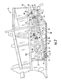
- FIG. 2 illustrates the manner in which sieves 18 and 22 may be suspended from a structural frame 30 of combine 10 by pivoting support arms 32 and 34, respectively, for reciprocal fore and aft movement denoted by arrow B.
- Such movement may be readily effected by various suitable and well known reciprocating drive mechanisms (not shown) that operate in well-known manners.
- Clean grain and tailings conveying system 12 is depicted as being fixedly connected or mounted below lower sieve 22 of cleaning system 20 to structural frame 30 by brackets 36 and 38, so as to be immovable relative to structural frame 30.
- the sieves 18 and 22 may be configured with an assembly 100 for directing pressurized jets air via ports 110 in a pulsating or continuous manner through the sieve elements 18, 22 to enhance the separating action.
- the clean grain and tailings conveying system 12 of Figs. 1 and 2 generally includes a pan 40 that is fixedly mounted to structural frame 30 by brackets 36 and 38 so as to be located directly beneath lower sieve 22.
- This pan 40 may include an array of elongated, longitudinally extending collecting troughs 42 positioned side-by-side across the width of pan 40.
- Such collecting troughs 42 generally extend in the fore and aft direction, between a forward edge 48 and a rear edge 50 of trough 42.
- Each collecting trough 42 has a clean grain receiving portion 52 located beneath those regions of lower sieve 22 through which clean grain is expected to fall, and a tailings receiving portion 54 positioned beneath peripheral edge portion 28 of lower sieve 22.
- a deflector shield 56 is preferably disposed beneath the rear end portion of lower sieve 22 to deflect clean grain onto clean grain receiving portion 52 of pan 40, as opposed to tailings receiving portion 54 located below the rear end.
- a clean grain auger trough 58 is disposed generally cross-wise to and in communication with the clean grain collecting troughs 42 of clean grain receiving portion 52 such that clean grain can be conveyed through the clean grain collecting troughs to the clean grain auger trough.
- a tailings auger trough 60 is disposed generally cross-wise to and in communication with the tailings collector troughs 42 of tailings receiving portion 54.
- An elongated, helical auger 62 is supported in each collecting trough 42, with each auger 62 including a first helical auger flight 64 extending in a first predetermined rotational direction and a second helical auger flight 66 and third auger flight 68 extending in a second rotational direction opposite the first rotational direction.
- Each auger 62 is connected to a drive mechanism, which may include a bevel gear 70 on the rear end of auger 62 that meshes with a drive gear (not shown) rotated by any suitable drive, such as a belt, chain or shaft, in connection with a power plant of combine 10 (not shown).
- flights 64, 66, and 68 will convey clean grain and tailings separately and simultaneously along collecting troughs 42, with clean grain from the clean grain collecting troughs being moved into clean grain auger trough 58 and tailings from the tailings collector troughs being moved into tailings auger trough 60.
- Clean grain auger trough 58 preferably has a helical auger 76 associated therewith and tailings auger trough 60 preferably has a similar auger 78 associated therewith, which augers are rotatable in the conventional manner using suitable drives (not shown) for conveying the clean grain and tailings, respectively, to a clean grain elevator (not shown) and a tailings return system (also not shown), in well-known manners.
- a sieve assembly 100 incorporating aspects of the present invention is depicted.
- Either or both of the upper sieve 18 and lower sieve 22 are configured with a plurality of air ports 110 disposed along the respective frame structure 102 ( Fig. 3 ) of the sieve elements.
- the air ports 110 are distributed in a pattern and are oriented at an angle so as to direct pressurized air upwardly through the sieve elements, as graphically depicted in Fig. 2 .
- the air ports 110 are in communication with a source of pressurized air, as discussed in greater detail below.
- the air ports 110 are preferably provided in a number and arranged in a pattern so as to provide generally uniform coverage over the surface area of the respective sieves 18, 22.
- the pressurized air discharged from the ports 110 may be continuous in one embodiment, or may be pulsed in another embodiment.
- the air may be in addition to the air provided by the fan 26 ( Fig. 1 ) or, in certain embodiments, the assembly 100 may replace the fan 26.
- the air jets from the ports 110 serve to break up the clusters of grain and MOG that may accumulate and roll on the sieve, as discussed above.
- the sieve assembly 100 includes a frame structure 102 typically comprised of longitudinal members 106 and transverse members 104 that define a grid-type configuration.
- Sieve elements 108 are supported by the frame structure 102.
- the invention is not limited by any particular type of sieve element 108 or frame structure 102.
- Typical sieve elements 102 may be louver elements, as is generally well-known in the art and need not be described in detail herein.
- the frame structure 112 may be defined by internal air conduits 114 within the frame structure elements 104, 106.
- the structural elements 104, 106 may be generally hollow tubular elements that are in communication with a pressurized air source via a connection 105.
- Fig. 4 is a bottom view of this particular embodiment and illustrates that the frame member elements 104, 106 define an internal conduit grid 116 below the sieve elements 108.
- Air ports (not visible in Fig. 4 ) are in communication with the internal air conduits 114 for directing the pressurized air from the internal air conduit grid 116 at the desired angular orientation relative to the sieve elements 108.
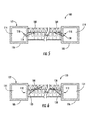
- FIG. 5 an end cross-sectional view of a particular embodiment of a sieve assembly 100 is depicted wherein the air ports 110 that direct the pressurized air from the internal air conduits 114 are defined simply as holes 118 in the structural frame members 106.
- the holes 118 are defined at a desired angular orientation so as to direct the pressurized air upwards and through the respective sieve elements 108, as generally depicted by the flow arrows in Fig. 5 .
- the air ports 110 are defined by nozzles 120 that are mounted onto the structural frame members 106. These nozzles 120 may be fixed in position or adjustable and serve to direct the pressurized air upwards through the sieve elements 108.
- Fig. 7 depicts an embodiment wherein a grid configuration 124 of external conduit members 122 is provided for attachment to the structural members 104, 106 of the frame structure 102 by any suitable means.
- the external conduits 122 may be, for example, tubular members that are also defined into a grid 124 that may essentially compliment or match the grid configuration of the frame structure 102 so as to be securely mounted to the underside of the frame structure elements 104, 106.
- the external conduits 122 may be spaced between the structural members 106, 104 of the frame structure 102.
- the external conduits are provided with a plurality of air ports 110 in a number and pattern so as to define a desired degree of coverage below the surface area of the sieve elements 108.
- the invention is not limited to any particular number of air ports 110 or pattern.
- the air ports 110 are nozzles 120, which may be fixed or adjustable.
- the air ports 110 may, in an alternate embodiment, be defined simply as holes 118 ( Fig. 5 ) defined in the external conduits 122.
- the sieve assembly 100 may be provided with a source of pressurized air via any suitable existing system on the combine 10 ( Fig. 1 ).
- the combine 10 may include an air compressor 126 that serves various engine and/or other operational functions.
- This compressor 126 may be used to charge an accumulator or tank 128 that supplies pressurized air to the frame structure 102 (or external conduit grid 124).
- Discharge from the air tank 128 may be controlled by a controllable valve 130, such as a solenoid valve, that is cycled by a system controller 132 to provide either continuous or pulsed air through the sieve assembly 100, as discussed above.
- a dedicated air compressor or other pressurized air source may be provided within the combine 10 for supplying the sieve assembly 100.
- Fig. 9 depicts an embodiment of a sieve assembly 100 in accordance with aspects of the invention wherein the pressurized air source 112 is functionally provided by the reciprocating drive 134 used to drive the sieve frame structure 102 in its vibratory to-and-fro motion, as discussed above.
- the reciprocating drive 134 utilizes a cam to drive a crank arm 136 connected to the frame structure 102.
- the frame structure 102 typically returns to a home position under its own weight and inertia after the power stroke of the crank arm 136, which in turn causes the crank arm 136 or cam to return to a corresponding home position.
- this return stroke must be buffered or dampened.
- the energy of the return stroke of the drive mechanism 134 is harnessed to drive a compressor mechanism 140, such as an air piston.
- the drive mechanism 134 is mechanically connected to the compressor mechanism 140 through any manner of suitable linkage in order to drive the mechanism 140.
- a second crank arm 138 may be operably connected to the drive mechanism 134 so that on the return stroke of the drive mechanism, the crank arm drives piston within an air piston embodiment of the compressor mechanism 140.
- the output of this mechanism 140 may be used to charge an accumulator or tank 128, which then supplies the pressurized air via a control valve 130 to the frame structure 102 under the control of a controller 132.
- an embodiment similar to that depicted in Fig. 9 may be provided within the drive mechanism 134 also charges the air tank 128 via a compressor mechanism 140 on the positive drive stroke of the drive mechanism 134, instead of on the passive return stroke as discussed above.
- Fig. 10 depicts an embodiment of a sieve assembly 100 wherein the air ports 110 are defined on the individual sieve elements 108 instead of or in combination with ports defined on the frame structure 102.
- the frame structure 102 may define internal air conduits 114 in the transverse members 104 and longitudinal members 106 that are supplied with pressurized air via any suitable air supply 112 (including those discussed above).
- the individual sieve elements 108 include internal air passages 115 that are in flow communication with the internal air conduits 114 such that pressurized air is conducted from the frame members 102 to the sieve elements 108.
- the sieve elements 108 may be defined by shell members that define a generally hollow interior volume that is in flow communication with the internal conduits 114 such that pressurized air is introduced directly into the individual louvers of the sieve elements 108.
- any manner of external or internal conduit members, such as tubing or piping, may be configured within or external to the sieve elements, with such conduit members being in flow communication with the internal conduits 114 of the frame members 102.
- any pattern of ports 110 may be defined along any one or combination of the sieve elements 108. It is not necessary that every louver of the sieve elements have a port 110.
- the ports 110 are supplied in a number and pattern to provide an effective cleaning of the sieve elements 108.
- Fig. 11 depicts an embodiment of a sieve assembly 100 similar to the embodiment of Fig. 8 discussed above wherein an air compressor 126 that serves various engine and/or other operational functions is used to charge an accumulator or tank 128 that supplies pressurized air to the frame structure 102 (or external conduit grid 124) via connections 105. Discharge from the air tank 128 may be controlled by multiple controllable valves 130, such as solenoid valves, that are cycled by a system controller 132 to provide either continuous or pulsed air through the sieve assembly 100.
- the use of multiple valves 130 allows for different control parameters for different parts or sections of the sieve assembly 100. For example a front blast pattern may be generated that is different from a rear blast pattern, and so forth. It should be appreciated that various configurations of valves 130 and different control patterns are within the scope of the invention.
- Figs. 12A through 12C depict various air blast frequency and period patterns that may be utilized in any one of the sieve assemblies 100 in accordance with aspects of the invention.
- the nozzles may blow air jets at any designed frequency or period (e.g., by appropriate control of valves 130) depending on any number of factors, such as type of crop being harvested, and the like.
- Fig. 12A depicts a relatively long air blast period relative to sieve motion as compared, for example, to Fig. 12B.
- Fig. 12C depicts a random air blast period relative to sieve motion.
Landscapes
- Life Sciences & Earth Sciences (AREA)
- Environmental Sciences (AREA)
- Combined Means For Separation Of Solids (AREA)
- Combines (AREA)
Applications Claiming Priority (1)
| Application Number | Priority Date | Filing Date | Title |
|---|---|---|---|
| US13/614,045 US8651927B1 (en) | 2012-09-13 | 2012-09-13 | Combine harvester sieve assembly with an integrated air cleaning system |
Publications (2)
| Publication Number | Publication Date |
|---|---|
| EP2708111A1 true EP2708111A1 (de) | 2014-03-19 |
| EP2708111B1 EP2708111B1 (de) | 2018-11-14 |
Family
ID=49230506
Family Applications (1)
| Application Number | Title | Priority Date | Filing Date |
|---|---|---|---|
| EP13184468.0A Active EP2708111B1 (de) | 2012-09-13 | 2013-09-13 | Mähdrescher-Siebanordnung mit integriertem Luftreinigungssystem |
Country Status (3)
| Country | Link |
|---|---|
| US (1) | US8651927B1 (de) |
| EP (1) | EP2708111B1 (de) |
| BR (1) | BR102013023432B1 (de) |
Cited By (2)
| Publication number | Priority date | Publication date | Assignee | Title |
|---|---|---|---|---|
| DE102016103234A1 (de) | 2016-02-24 | 2017-08-24 | Claas Selbstfahrende Erntemaschinen Gmbh | Verfahren zum Betreiben einer Reinigungseinrichtung für einen Mähdrescher |
| RU2690480C1 (ru) * | 2018-03-12 | 2019-06-03 | федеральное государственное бюджетное образовательное учреждение высшего образования "Марийский государственный университет" | Жалюзийное решето |
Families Citing this family (17)
| Publication number | Priority date | Publication date | Assignee | Title |
|---|---|---|---|---|
| BE1021154B1 (nl) * | 2013-07-02 | 2016-10-26 | Cnh Industrial Belgium Nv | Maaidorser met meertrapsgraanvoorbereiding |
| GB2526248A (en) * | 2014-03-17 | 2015-11-25 | Caterpillar Inc | Grill Assembly |
| US10123524B2 (en) | 2014-06-19 | 2018-11-13 | Cnh Industrial Canada, Ltd. | Active system for optimization and plugging avoidance of seed/fertilizer in transport conducts |
| US9295197B1 (en) | 2014-10-14 | 2016-03-29 | Cnh Industrial America Llc | Combine harvester with blower equipped elevator |
| US10257983B2 (en) * | 2014-12-17 | 2019-04-16 | Agco International Gmbh | Crop processing apparatus in a combine harvester |
| BE1022661B1 (nl) * | 2015-03-31 | 2016-06-29 | Cnh Industrial Belgium Nv | Verbeteringen van of betreffende graanreinigers voor maaidorsers |
| US10827682B2 (en) * | 2018-10-02 | 2020-11-10 | Deere & Company | Independent air controlled sieve |
| US11395984B2 (en) | 2019-05-24 | 2022-07-26 | Flory Industries | Dust control system and related methods |
| US12114606B2 (en) * | 2019-05-31 | 2024-10-15 | Rocky Ford Harvesting, Llc | Automated hemp flower harvester machinery and apparatuses, methods relating to same |
| GB201915852D0 (en) | 2019-10-31 | 2019-12-18 | Agco Int Gmbh | Longitudinal sieve compensation |
| US11266053B2 (en) | 2019-11-07 | 2022-03-08 | Cnh Industrial Canada, Ltd. | Fluid nozzle system and method for de-plugging ground engaging tools of an agricultural implement |
| US11877538B1 (en) | 2022-08-30 | 2024-01-23 | Calmer Holding Company, Llc | Threshing grains and legumes utilizing concaves with adjustable openings |
| USD1031793S1 (en) | 2022-08-30 | 2024-06-18 | Calmer Holding Company, Llc | Separating grate |
| USD1031792S1 (en) | 2022-08-30 | 2024-06-18 | Calmer Holding Company, Llc | Round bar concave |
| USD1032666S1 (en) | 2022-08-30 | 2024-06-25 | Calmer Holding Company, Llc | MOG limiting subassembly for combine concave |
| USD1031791S1 (en) | 2022-08-30 | 2024-06-18 | Calmer Holding Company, Llc | Straight bar concave |
| USD1058613S1 (en) | 2022-11-29 | 2025-01-21 | Calmer Holding Company, Llc | Limiter plates |
Citations (3)
| Publication number | Priority date | Publication date | Assignee | Title |
|---|---|---|---|---|
| DE1115508B (de) * | 1960-08-01 | 1961-10-19 | Helmut Claas Dipl Ing | Windverteiler unter den Sieben der Druckwindreinigung eines Maehdreschers |
| GB2025746A (en) * | 1978-07-08 | 1980-01-30 | Deere & Co | Axial Flow Combine Harvester |
| EP0475453A2 (de) * | 1990-09-13 | 1992-03-18 | SAME S.p.A. | Vorrichtung für Getreidereinigung in einem Mähdrescher |
Family Cites Families (36)
| Publication number | Priority date | Publication date | Assignee | Title |
|---|---|---|---|---|
| US2240779A (en) * | 1939-04-29 | 1941-05-06 | Wood Brothers Thresher Company | Grain separator |
| US2250383A (en) * | 1939-10-12 | 1941-07-22 | Henry D Koester | Air controlled sieve for threshing machines |
| US2692679A (en) * | 1950-07-21 | 1954-10-26 | John R Lindberg | Grain leveling device |
| US2694493A (en) * | 1952-02-08 | 1954-11-16 | Carl O Odegarden | Blower attachment for combines |
| US3116236A (en) * | 1960-08-01 | 1963-12-31 | Claas Helmut | Grills of combine harvesters |
| US3334739A (en) * | 1964-04-22 | 1967-08-08 | Ransomes Sims & Jefferies | Dressing shoes for grain threshing mechanisms |
| US3374886A (en) * | 1966-05-02 | 1968-03-26 | Arthur S. Lightsey | Grain separator chaffer assembly |
| US4017206A (en) | 1975-09-03 | 1977-04-12 | Veb Kombinat Fortschritt Landmaschinen | Winnowing blower for combine harvester-thresher |
| LU77527A1 (de) | 1976-06-18 | 1977-09-26 | ||
| DE2842702C2 (de) * | 1978-09-30 | 1982-07-01 | Deere & Co., Moline, Ill., US, Niederlassung Deere & Co. European Office, 6800 Mannheim | Reinigungsvorrichtung für Mähdrescher |
| DE3173652D1 (en) * | 1981-10-21 | 1986-03-13 | Deere & Co | Grain pan for harvesters |
| US5176574A (en) * | 1991-06-24 | 1993-01-05 | Case Corporation | Combine cleaning system |
| DE4222364A1 (de) | 1992-07-08 | 1994-01-13 | Claas Ohg | Vorrichtung zum Sichten und Sieben von Schüttgütern und selbstfahrender Mähdrescher mit einer derartigen Vorrichtung |
| JP3151355B2 (ja) * | 1994-05-09 | 2001-04-03 | 株式会社クボタ | 脱穀装置の選別部構造 |
| GB2293080A (en) * | 1994-09-17 | 1996-03-20 | New Holland Belguim Nv | Grain cleaner for combine harvester |
| US6053812A (en) * | 1997-11-24 | 2000-04-25 | Loewen Manufacturing Co. | Sieve construction for a combine harvester |
| AUPP111997A0 (en) * | 1997-12-24 | 1998-01-22 | M E Mckay & Associates Pty Ltd | Separation using air flows of different velocities |
| DE19807145C2 (de) * | 1998-02-20 | 1999-12-09 | Claas Selbstfahr Erntemasch | Mähdrescher mit Vorrichtung zur automatischen Reinigungseinstellung |
| US6475082B2 (en) * | 1998-08-18 | 2002-11-05 | Claas Selbstfahrende Erntemaschinen Gmbh | Flap openings in a grain harvesting threshing and separation unit |
| GB2365312A (en) * | 2000-08-01 | 2002-02-20 | Claas Selbstfahr Erntemasch | Grain cleaning apparatus for combines |
| US6790137B2 (en) * | 2002-01-25 | 2004-09-14 | Marvin James Gorden | High capacity air jet chaffer |
| DE10225090A1 (de) | 2002-06-05 | 2003-12-18 | Claas Selbstfahr Erntemasch | Kühlluft-Reinigungseinrichtung |
| US6773343B2 (en) * | 2002-07-31 | 2004-08-10 | Deere & Company | Front chaffer and cleaning fan |
| US7028844B2 (en) | 2003-07-17 | 2006-04-18 | Nelson Robert D | Dried lavender flower separator system and method |
| DE10360597A1 (de) * | 2003-12-19 | 2005-07-28 | Claas Selbstfahrende Erntemaschinen Gmbh | Verfahren und Vorrichtung zur Regelung von Arbeitsorganen eines Mähdreschers |
| US7022013B1 (en) | 2004-11-17 | 2006-04-04 | Cnh America Llc | Axial flow combine harvester with adaptable separating unit |
| ATE531440T1 (de) | 2005-03-31 | 2011-11-15 | Donaldson Co Inc | Luftreiniger-anordnung |
| DE102005056115A1 (de) | 2005-11-23 | 2007-05-24 | Claas Selbstfahrende Erntemaschinen Gmbh | Mähdrescher mit Sauggebläse |
| US8434624B2 (en) * | 2007-10-15 | 2013-05-07 | Redekop Enterprises Inc | Harvesting corn cobs |
| CA2692568C (en) * | 2007-10-15 | 2011-05-31 | Redekop Enterprises Inc. | Harvesting corn cobs |
| US8591301B2 (en) * | 2007-10-19 | 2013-11-26 | Redekop Enterprises Inc. | Collecting corn cobs in a cart towed behind a combine harvester |
| US7927198B2 (en) * | 2007-11-08 | 2011-04-19 | Redekop Enterprises Inc. | Harvester corn cobs separating |
| US7585213B2 (en) | 2008-01-18 | 2009-09-08 | Cnh America Llc | Auger trough clean-out door |
| GB0812966D0 (en) | 2008-07-16 | 2008-08-20 | Cnh Belgium Nv | Cleaning of an air filter screen of an agricultural vehicle |
| US7896731B2 (en) * | 2008-12-08 | 2011-03-01 | Cnh America Llc | Combine grain cleaning system including a grain cleaning sieve having a region of increased grain throughput |
| DE102010016670A1 (de) | 2010-04-28 | 2011-11-03 | Claas Selbstfahrende Erntemaschinen Gmbh | Drescheinrichtung für Mähdrescher |
-
2012
- 2012-09-13 US US13/614,045 patent/US8651927B1/en active Active
-
2013
- 2013-09-12 BR BR102013023432-0A patent/BR102013023432B1/pt not_active IP Right Cessation
- 2013-09-13 EP EP13184468.0A patent/EP2708111B1/de active Active
Patent Citations (3)
| Publication number | Priority date | Publication date | Assignee | Title |
|---|---|---|---|---|
| DE1115508B (de) * | 1960-08-01 | 1961-10-19 | Helmut Claas Dipl Ing | Windverteiler unter den Sieben der Druckwindreinigung eines Maehdreschers |
| GB2025746A (en) * | 1978-07-08 | 1980-01-30 | Deere & Co | Axial Flow Combine Harvester |
| EP0475453A2 (de) * | 1990-09-13 | 1992-03-18 | SAME S.p.A. | Vorrichtung für Getreidereinigung in einem Mähdrescher |
Cited By (3)
| Publication number | Priority date | Publication date | Assignee | Title |
|---|---|---|---|---|
| DE102016103234A1 (de) | 2016-02-24 | 2017-08-24 | Claas Selbstfahrende Erntemaschinen Gmbh | Verfahren zum Betreiben einer Reinigungseinrichtung für einen Mähdrescher |
| EP3210461A1 (de) | 2016-02-24 | 2017-08-30 | CLAAS Selbstfahrende Erntemaschinen GmbH | Verfahren zum betreiben einer reinigungseinrichtung für einen mähdrescher |
| RU2690480C1 (ru) * | 2018-03-12 | 2019-06-03 | федеральное государственное бюджетное образовательное учреждение высшего образования "Марийский государственный университет" | Жалюзийное решето |
Also Published As
| Publication number | Publication date |
|---|---|
| BR102013023432B1 (pt) | 2019-09-17 |
| BR102013023432A8 (pt) | 2016-12-06 |
| EP2708111B1 (de) | 2018-11-14 |
| US20140073380A1 (en) | 2014-03-13 |
| US8651927B1 (en) | 2014-02-18 |
| BR102013023432A2 (pt) | 2014-12-09 |
Similar Documents
| Publication | Publication Date | Title |
|---|---|---|
| EP2708111B1 (de) | Mähdrescher-Siebanordnung mit integriertem Luftreinigungssystem | |
| US6672957B2 (en) | Combine harvester cleaning apparatus | |
| US7427232B2 (en) | Clean grain and tailings conveying system for an agricultural combine | |
| EP3563661B1 (de) | Siebanordnung für ein erntegutbearbeitungssystem einer landwirtschaftlichen erntemaschine | |
| EP3071013A1 (de) | Konkaves system und verfahren für eine landwirtschaftliche erntemaschine | |
| CN103313593A (zh) | 联合收割机谷粒清洁装置 | |
| US11259466B2 (en) | Agricultural elevator supplied by multiple cross augers | |
| EP2695507B1 (de) | Mähdreschersiebanordnung mit Schneckentrog-Reinigungsanordnung | |
| EP3087825B1 (de) | Schneckenanordnung für landwirtschaftliche erntemaschine | |
| EP1849350B1 (de) | Fördersystem für Korn und Überkehr für einen Mähdrescher | |
| JP2019208390A (ja) | コンバイン | |
| EP4640036A1 (de) | Kraftoptimierung auf ein kornreinigungsantriebssystem eines mähdreschers | |
| WO2016176587A1 (en) | Agricultural harvester auger assembly | |
| BR102019010154A2 (pt) | crivo para uma colheitadeira, crivo estacionário para uma colheitadeira, e, colheitadeira para colher e limpar uma safra. |
Legal Events
| Date | Code | Title | Description |
|---|---|---|---|
| PUAI | Public reference made under article 153(3) epc to a published international application that has entered the european phase |
Free format text: ORIGINAL CODE: 0009012 |
|
| AK | Designated contracting states |
Kind code of ref document: A1 Designated state(s): AL AT BE BG CH CY CZ DE DK EE ES FI FR GB GR HR HU IE IS IT LI LT LU LV MC MK MT NL NO PL PT RO RS SE SI SK SM TR |
|
| AX | Request for extension of the european patent |
Extension state: BA ME |
|
| RAP1 | Party data changed (applicant data changed or rights of an application transferred) |
Owner name: CNH INDUSTRIAL BELGIUM NV |
|
| 17P | Request for examination filed |
Effective date: 20140919 |
|
| RBV | Designated contracting states (corrected) |
Designated state(s): AL AT BE BG CH CY CZ DE DK EE ES FI FR GB GR HR HU IE IS IT LI LT LU LV MC MK MT NL NO PL PT RO RS SE SI SK SM TR |
|
| STAA | Information on the status of an ep patent application or granted ep patent |
Free format text: STATUS: EXAMINATION IS IN PROGRESS |
|
| 17Q | First examination report despatched |
Effective date: 20170901 |
|
| GRAP | Despatch of communication of intention to grant a patent |
Free format text: ORIGINAL CODE: EPIDOSNIGR1 |
|
| STAA | Information on the status of an ep patent application or granted ep patent |
Free format text: STATUS: GRANT OF PATENT IS INTENDED |
|
| INTG | Intention to grant announced |
Effective date: 20180607 |
|
| RIN1 | Information on inventor provided before grant (corrected) |
Inventor name: ROBERGE, MARTIN Inventor name: FARLEY, HERBERT M. Inventor name: RICKETTS, JONATHAN E. |
|
| GRAS | Grant fee paid |
Free format text: ORIGINAL CODE: EPIDOSNIGR3 |
|
| GRAA | (expected) grant |
Free format text: ORIGINAL CODE: 0009210 |
|
| STAA | Information on the status of an ep patent application or granted ep patent |
Free format text: STATUS: THE PATENT HAS BEEN GRANTED |
|
| AK | Designated contracting states |
Kind code of ref document: B1 Designated state(s): AL AT BE BG CH CY CZ DE DK EE ES FI FR GB GR HR HU IE IS IT LI LT LU LV MC MK MT NL NO PL PT RO RS SE SI SK SM TR |
|
| REG | Reference to a national code |
Ref country code: CH Ref legal event code: EP Ref country code: AT Ref legal event code: REF Ref document number: 1063703 Country of ref document: AT Kind code of ref document: T Effective date: 20181115 |
|
| REG | Reference to a national code |
Ref country code: DE Ref legal event code: R096 Ref document number: 602013046590 Country of ref document: DE |
|
| REG | Reference to a national code |
Ref country code: IE Ref legal event code: FG4D |
|
| REG | Reference to a national code |
Ref country code: NL Ref legal event code: MP Effective date: 20181114 |
|
| REG | Reference to a national code |
Ref country code: LT Ref legal event code: MG4D |
|
| REG | Reference to a national code |
Ref country code: AT Ref legal event code: MK05 Ref document number: 1063703 Country of ref document: AT Kind code of ref document: T Effective date: 20181114 |
|
| PG25 | Lapsed in a contracting state [announced via postgrant information from national office to epo] |
Ref country code: AT Free format text: LAPSE BECAUSE OF FAILURE TO SUBMIT A TRANSLATION OF THE DESCRIPTION OR TO PAY THE FEE WITHIN THE PRESCRIBED TIME-LIMIT Effective date: 20181114 Ref country code: HR Free format text: LAPSE BECAUSE OF FAILURE TO SUBMIT A TRANSLATION OF THE DESCRIPTION OR TO PAY THE FEE WITHIN THE PRESCRIBED TIME-LIMIT Effective date: 20181114 Ref country code: LT Free format text: LAPSE BECAUSE OF FAILURE TO SUBMIT A TRANSLATION OF THE DESCRIPTION OR TO PAY THE FEE WITHIN THE PRESCRIBED TIME-LIMIT Effective date: 20181114 Ref country code: ES Free format text: LAPSE BECAUSE OF FAILURE TO SUBMIT A TRANSLATION OF THE DESCRIPTION OR TO PAY THE FEE WITHIN THE PRESCRIBED TIME-LIMIT Effective date: 20181114 Ref country code: BG Free format text: LAPSE BECAUSE OF FAILURE TO SUBMIT A TRANSLATION OF THE DESCRIPTION OR TO PAY THE FEE WITHIN THE PRESCRIBED TIME-LIMIT Effective date: 20190214 Ref country code: LV Free format text: LAPSE BECAUSE OF FAILURE TO SUBMIT A TRANSLATION OF THE DESCRIPTION OR TO PAY THE FEE WITHIN THE PRESCRIBED TIME-LIMIT Effective date: 20181114 Ref country code: FI Free format text: LAPSE BECAUSE OF FAILURE TO SUBMIT A TRANSLATION OF THE DESCRIPTION OR TO PAY THE FEE WITHIN THE PRESCRIBED TIME-LIMIT Effective date: 20181114 Ref country code: IS Free format text: LAPSE BECAUSE OF FAILURE TO SUBMIT A TRANSLATION OF THE DESCRIPTION OR TO PAY THE FEE WITHIN THE PRESCRIBED TIME-LIMIT Effective date: 20190314 Ref country code: NO Free format text: LAPSE BECAUSE OF FAILURE TO SUBMIT A TRANSLATION OF THE DESCRIPTION OR TO PAY THE FEE WITHIN THE PRESCRIBED TIME-LIMIT Effective date: 20190214 |
|
| PG25 | Lapsed in a contracting state [announced via postgrant information from national office to epo] |
Ref country code: RS Free format text: LAPSE BECAUSE OF FAILURE TO SUBMIT A TRANSLATION OF THE DESCRIPTION OR TO PAY THE FEE WITHIN THE PRESCRIBED TIME-LIMIT Effective date: 20181114 Ref country code: NL Free format text: LAPSE BECAUSE OF FAILURE TO SUBMIT A TRANSLATION OF THE DESCRIPTION OR TO PAY THE FEE WITHIN THE PRESCRIBED TIME-LIMIT Effective date: 20181114 Ref country code: GR Free format text: LAPSE BECAUSE OF FAILURE TO SUBMIT A TRANSLATION OF THE DESCRIPTION OR TO PAY THE FEE WITHIN THE PRESCRIBED TIME-LIMIT Effective date: 20190215 Ref country code: PT Free format text: LAPSE BECAUSE OF FAILURE TO SUBMIT A TRANSLATION OF THE DESCRIPTION OR TO PAY THE FEE WITHIN THE PRESCRIBED TIME-LIMIT Effective date: 20190314 Ref country code: AL Free format text: LAPSE BECAUSE OF FAILURE TO SUBMIT A TRANSLATION OF THE DESCRIPTION OR TO PAY THE FEE WITHIN THE PRESCRIBED TIME-LIMIT Effective date: 20181114 Ref country code: SE Free format text: LAPSE BECAUSE OF FAILURE TO SUBMIT A TRANSLATION OF THE DESCRIPTION OR TO PAY THE FEE WITHIN THE PRESCRIBED TIME-LIMIT Effective date: 20181114 |
|
| PG25 | Lapsed in a contracting state [announced via postgrant information from national office to epo] |
Ref country code: PL Free format text: LAPSE BECAUSE OF FAILURE TO SUBMIT A TRANSLATION OF THE DESCRIPTION OR TO PAY THE FEE WITHIN THE PRESCRIBED TIME-LIMIT Effective date: 20181114 Ref country code: DK Free format text: LAPSE BECAUSE OF FAILURE TO SUBMIT A TRANSLATION OF THE DESCRIPTION OR TO PAY THE FEE WITHIN THE PRESCRIBED TIME-LIMIT Effective date: 20181114 Ref country code: IT Free format text: LAPSE BECAUSE OF FAILURE TO SUBMIT A TRANSLATION OF THE DESCRIPTION OR TO PAY THE FEE WITHIN THE PRESCRIBED TIME-LIMIT Effective date: 20181114 Ref country code: CZ Free format text: LAPSE BECAUSE OF FAILURE TO SUBMIT A TRANSLATION OF THE DESCRIPTION OR TO PAY THE FEE WITHIN THE PRESCRIBED TIME-LIMIT Effective date: 20181114 |
|
| REG | Reference to a national code |
Ref country code: DE Ref legal event code: R097 Ref document number: 602013046590 Country of ref document: DE |
|
| PG25 | Lapsed in a contracting state [announced via postgrant information from national office to epo] |
Ref country code: SK Free format text: LAPSE BECAUSE OF FAILURE TO SUBMIT A TRANSLATION OF THE DESCRIPTION OR TO PAY THE FEE WITHIN THE PRESCRIBED TIME-LIMIT Effective date: 20181114 Ref country code: EE Free format text: LAPSE BECAUSE OF FAILURE TO SUBMIT A TRANSLATION OF THE DESCRIPTION OR TO PAY THE FEE WITHIN THE PRESCRIBED TIME-LIMIT Effective date: 20181114 Ref country code: SM Free format text: LAPSE BECAUSE OF FAILURE TO SUBMIT A TRANSLATION OF THE DESCRIPTION OR TO PAY THE FEE WITHIN THE PRESCRIBED TIME-LIMIT Effective date: 20181114 Ref country code: RO Free format text: LAPSE BECAUSE OF FAILURE TO SUBMIT A TRANSLATION OF THE DESCRIPTION OR TO PAY THE FEE WITHIN THE PRESCRIBED TIME-LIMIT Effective date: 20181114 |
|
| PLBE | No opposition filed within time limit |
Free format text: ORIGINAL CODE: 0009261 |
|
| STAA | Information on the status of an ep patent application or granted ep patent |
Free format text: STATUS: NO OPPOSITION FILED WITHIN TIME LIMIT |
|
| 26N | No opposition filed |
Effective date: 20190815 |
|
| PG25 | Lapsed in a contracting state [announced via postgrant information from national office to epo] |
Ref country code: SI Free format text: LAPSE BECAUSE OF FAILURE TO SUBMIT A TRANSLATION OF THE DESCRIPTION OR TO PAY THE FEE WITHIN THE PRESCRIBED TIME-LIMIT Effective date: 20181114 |
|
| PG25 | Lapsed in a contracting state [announced via postgrant information from national office to epo] |
Ref country code: TR Free format text: LAPSE BECAUSE OF FAILURE TO SUBMIT A TRANSLATION OF THE DESCRIPTION OR TO PAY THE FEE WITHIN THE PRESCRIBED TIME-LIMIT Effective date: 20181114 |
|
| PG25 | Lapsed in a contracting state [announced via postgrant information from national office to epo] |
Ref country code: MC Free format text: LAPSE BECAUSE OF FAILURE TO SUBMIT A TRANSLATION OF THE DESCRIPTION OR TO PAY THE FEE WITHIN THE PRESCRIBED TIME-LIMIT Effective date: 20181114 |
|
| REG | Reference to a national code |
Ref country code: CH Ref legal event code: PL |
|
| PG25 | Lapsed in a contracting state [announced via postgrant information from national office to epo] |
Ref country code: LU Free format text: LAPSE BECAUSE OF NON-PAYMENT OF DUE FEES Effective date: 20190913 Ref country code: CH Free format text: LAPSE BECAUSE OF NON-PAYMENT OF DUE FEES Effective date: 20190930 Ref country code: LI Free format text: LAPSE BECAUSE OF NON-PAYMENT OF DUE FEES Effective date: 20190930 Ref country code: IE Free format text: LAPSE BECAUSE OF NON-PAYMENT OF DUE FEES Effective date: 20190913 |
|
| REG | Reference to a national code |
Ref country code: BE Ref legal event code: MM Effective date: 20190930 |
|
| PG25 | Lapsed in a contracting state [announced via postgrant information from national office to epo] |
Ref country code: BE Free format text: LAPSE BECAUSE OF NON-PAYMENT OF DUE FEES Effective date: 20190930 |
|
| GBPC | Gb: european patent ceased through non-payment of renewal fee |
Effective date: 20190913 |
|
| PG25 | Lapsed in a contracting state [announced via postgrant information from national office to epo] |
Ref country code: GB Free format text: LAPSE BECAUSE OF NON-PAYMENT OF DUE FEES Effective date: 20190913 |
|
| PG25 | Lapsed in a contracting state [announced via postgrant information from national office to epo] |
Ref country code: CY Free format text: LAPSE BECAUSE OF FAILURE TO SUBMIT A TRANSLATION OF THE DESCRIPTION OR TO PAY THE FEE WITHIN THE PRESCRIBED TIME-LIMIT Effective date: 20181114 |
|
| PG25 | Lapsed in a contracting state [announced via postgrant information from national office to epo] |
Ref country code: MT Free format text: LAPSE BECAUSE OF FAILURE TO SUBMIT A TRANSLATION OF THE DESCRIPTION OR TO PAY THE FEE WITHIN THE PRESCRIBED TIME-LIMIT Effective date: 20181114 Ref country code: HU Free format text: LAPSE BECAUSE OF FAILURE TO SUBMIT A TRANSLATION OF THE DESCRIPTION OR TO PAY THE FEE WITHIN THE PRESCRIBED TIME-LIMIT; INVALID AB INITIO Effective date: 20130913 |
|
| PG25 | Lapsed in a contracting state [announced via postgrant information from national office to epo] |
Ref country code: MK Free format text: LAPSE BECAUSE OF FAILURE TO SUBMIT A TRANSLATION OF THE DESCRIPTION OR TO PAY THE FEE WITHIN THE PRESCRIBED TIME-LIMIT Effective date: 20181114 |
|
| PGFP | Annual fee paid to national office [announced via postgrant information from national office to epo] |
Ref country code: DE Payment date: 20250926 Year of fee payment: 13 |
|
| PGFP | Annual fee paid to national office [announced via postgrant information from national office to epo] |
Ref country code: FR Payment date: 20250925 Year of fee payment: 13 |