EP2708333A2 - Appareil de robot pour transférer des objets à traiter - Google Patents
Appareil de robot pour transférer des objets à traiter Download PDFInfo
- Publication number
- EP2708333A2 EP2708333A2 EP13178340.9A EP13178340A EP2708333A2 EP 2708333 A2 EP2708333 A2 EP 2708333A2 EP 13178340 A EP13178340 A EP 13178340A EP 2708333 A2 EP2708333 A2 EP 2708333A2
- Authority
- EP
- European Patent Office
- Prior art keywords
- transfer
- processed objects
- distance
- determining section
- robot
- Prior art date
- Legal status (The legal status is an assumption and is not a legal conclusion. Google has not performed a legal analysis and makes no representation as to the accuracy of the status listed.)
- Withdrawn
Links
Images







Classifications
-
- B—PERFORMING OPERATIONS; TRANSPORTING
- B25—HAND TOOLS; PORTABLE POWER-DRIVEN TOOLS; MANIPULATORS
- B25J—MANIPULATORS; CHAMBERS PROVIDED WITH MANIPULATION DEVICES
- B25J9/00—Program-controlled manipulators
- B25J9/16—Program controls
- B25J9/1656—Program controls characterised by programming, planning systems for manipulators
- B25J9/1669—Program controls characterised by programming, planning systems for manipulators characterised by special application, e.g. multi-arm co-operation, assembly, grasping
-
- B—PERFORMING OPERATIONS; TRANSPORTING
- B25—HAND TOOLS; PORTABLE POWER-DRIVEN TOOLS; MANIPULATORS
- B25J—MANIPULATORS; CHAMBERS PROVIDED WITH MANIPULATION DEVICES
- B25J9/00—Program-controlled manipulators
- B25J9/16—Program controls
- B25J9/1679—Program controls characterised by the tasks executed
-
- G—PHYSICS
- G05—CONTROLLING; REGULATING
- G05B—CONTROL OR REGULATING SYSTEMS IN GENERAL; FUNCTIONAL ELEMENTS OF SUCH SYSTEMS; MONITORING OR TESTING ARRANGEMENTS FOR SUCH SYSTEMS OR ELEMENTS
- G05B2219/00—Program-control systems
- G05B2219/30—Nc systems
- G05B2219/40—Robotics, robotics mapping to robotics vision
- G05B2219/40053—Pick 3-D object from pile of objects
Definitions
- the present invention relates to a robot apparatus.
- Japanese Unexamined Patent Application Publication No. 2001-300878 discloses a robot main body disposed in a robot apparatus.
- the robot main body (multi-articular robot) includes a robot arm (arm) and a robot hand (magnet hand) mounted to a distal end of the robot arm.
- a pallet is placed on which a plurality of to-be-processed objects (iron workpieces) are randomly stacked. Then, the robot main body makes the robot hand suck one to-be-processed object after another out of the pallet.
- the robot hand transfers the to-be-processed objects in random order, or, simply, transfers the to-be-processed objects in distance ascending order relative to the robot main body.
- the transfer work makes uneven progress in time, which can make it difficult to perform smooth transfer work.
- the present invention has been made in view of the above-described circumstances, and it is an object of the present invention to provide a robot apparatus that ensures smooth transfer work.
- a robot apparatus includes a robot main body, a distance determining section, an order determining section, and an operation controlling section.
- the robot main body is configured to transfer a plurality of to-be-processed objects in order so as to subject every predetermined number of to-be-processed objects among the plurality of to-be-processed objects to processing, and includes a robot arm and a robot hand.
- the robot hand is configured to hold a to-be-processed object among the plurality of to-be-processed objects by at least one of gripping and suction.
- the distance determining section is configured to determine an entire transfer distance of each of the plurality of to-be-processed objects.
- the entire transfer distance is from a location of each of the plurality of to-be-processed objects to a transfer destination of each of the plurality of to-be-processed objects.
- the order determining section is configured to determine a transfer order of the plurality of to-be-processed objects based on a determination result of the distance determining section so that every predetermined number of the to-be-processed objects has uniform transfer time.
- the operation controlling section is configured to control an operation of the robot arm and an operation of the robot hand so as to transfer the plurality of to-be-processed objects in accordance with the transfer order determined by the order determining section.
- the present invention ensures smooth transfer work.
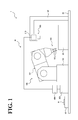
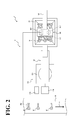
- a robot system 1 includes a stocker 20, a robot apparatus 10, and a conveyor 30.
- the stocker 20 is a box formed of, for example, reinforced resin, metal, or other material, and is disposed on a floor 40 in the vicinity (in the operable range) of a robot main body 100, described later, of the robot apparatus 10.
- the stocker 20 may not necessarily be disposed on the floor 40, but may be disposed on a pedestal or a like support disposed on the floor 40.
- a plurality of workpieces W (to-be-processed objects) are in stock in a random (scattered) manner.
- Each workpiece W has a head 61 and an arm 62.
- the head 61 has a through hole 61a.
- the arm 62 has a bar shape extending from the head 61.
- the workpiece W will not be limited to this shape, but may have any other shape.
- the robot apparatus 10 includes the robot main body 100, a robot controller 200, a sensor unit 300, and an image processing apparatus 400.
- the robot main body 100 and the robot controller 200 are communicatively coupled to one another through a wire or wirelessly.
- the robot controller may be disposed inside the robot main body 100.
- the robot controller 200 and the image processing apparatus 400 are communicatively coupled to one another through a wire or wirelessly.
- a sensor controller 310, described later, of the sensor unit 300 and the image processing apparatus 400 are communicatively coupled to one another through a wire or wirelessly.
- the image processing apparatus may be disposed inside the sensor unit 300.
- the robot main body 100 is what is called a multi-articular robot, and includes a base 101 and an arm 102 (robot arm).
- the base 101 is secured to the floor 40.
- the arm 102 is rotatably disposed on the base 101.
- the base 101 may not necessarily be secured to the floor 40, but may be secured to a pedestal or a like support disposed on the floor 40.
- the arm 102 has a plurality of joints (rotary joints) from the end of the arm 102 on the base 101 side to the opposite, distal end of the arm 102.
- the arm 102 has a plurality of built-in servo motors (not shown) to drive the plurality of joints.
- a hand 103 (robot hand) is disposed capable of holding a workpiece W by gripping or suction.
- the hand may be disposed at a portion of the arm 102 other than its distal end.
- the hand 103 is capable of holding the workpiece W by gripping or suction.
- examples include, but not limited to, a gripper with fingers capable of gripping the workpiece W, and a suction device driven pneumatically, electromagnetically, or by some other force to suck the workpiece W.
- the above-described gripper is employed as the hand 103, and hence, the hand device 103 will be also referred to as a gripper 103.
- the gripper 103 includes a pair of fingers 103a capable of gripping the workpiece W.
- the pair of fingers 103a are driven by a suitable actuator (not shown) built in the gripper 103 to make an open-close operation of expanding or diminishing the spacing between the pair of fingers 103a.
- the gripper 103 will not be limited to this structure, and other examples include, but not limited to, a gripper with a plurality of fingers that make a swinging movement to grip the workpiece W.
- the robot main body 100 performs transfer work (what is called Random Bin Picking) of the plurality of workpieces W disposed in the stocker 20. Specifically, the robot main body 100 grips the plurality of workpieces W disposed in the stocker 20 in order on a one-by-one basis using the fingers 103a of the gripper 103, and places the workpieces W on their transfer destination on the conveyor 30, namely, a predetermined workpiece placement position 30a, described later.
- the transfer destination of the workpieces W will not be limited to the workpiece placement position 30a on the conveyor 30, but may be elsewhere (examples include a part of the equipment associated with a post-processing step, described later).
- the transfer work by the robot main body 100 will be described in more detail later.
- the robot controller 200 is made up of a computer that includes, for example, an operator, a memory, and an input device.
- the robot controller 200 controls the operations of the robot main body 100 as a whole, which includes the arm 102 and the gripper 103 (for example, controls driving of the joints of the arm 102, and the open-close operation of the fingers 103a of the gripper 103).
- the robot controller 200 will be described in more detail later.
- the sensor unit 300 includes a laser scanner 301 and a camera 302.
- the sensor unit 300 is positioned over the stocker 20 while being supported by a suitable support 50 with the laser scanner 301 and the camera 302 facing downward.
- the support 50 is secured to the floor 40.
- the sensor unit 300 may be disposed at a suitable portion of the robot main body 100 (for example, the distal end of the arm 102).
- the laser scanner 301 includes a laser light source that generates slit-shaped laser light (hereinafter referred to as laser slit light), a mirror that reflects laser slit light, and a motor that rotates the mirror (all of which are not shown).
- the laser scanner 301 has its mirror reflect the laser slit light generated by the laser light source and has the motor rotate the mirror, thereby radiating, from above, the laser slit light to the entire region in which the workpieces W in the stocker 20 are possibly disposed (that is, the region in which all the workpieces W are disposed, which will be hereinafter also referred to as an inner-stocker 20 entire region).
- the laser scanner 301 collectively scans the workpieces W located in the inner-stocker 20 entire region.
- the camera 302 includes an image pick-up device (not shown) and other elements.
- the reflected objects for example, the workpieces W and the stocker 20 itself located in the inner-stocker 20 entire region reflect the laser slit light, which results in reflection light of the laser slit light.
- the camera 302 has its image pick-up device pick up an image of (receive) the reflection light of the laser slit light.
- the camera 302 has its image pick-up device pick up an image (grayscale image) from above the inner-stocker 20 entire region, and an image of the reflection light of the laser slit light reflected by the reflected objects located in the inner-stocker 20 entire region.
- the sensor controller 310 is built in.
- the sensor controller 310 is made up of a computer that includes, for example, an operator and a memory, and controls the operations of the sensor unit 300 as a whole, which includes the laser scanner 301 and the camera 302.
- the sensor controller 310 detects the distance to the reflected objects located in the inner-stocker 20 entire region using a known principle of triangulation based on the rotational angle of the motor (mirror), the position of the image pick-up device of the camera 302 at the time when the image pick-up device received light, and a positional relationship among the laser light source, the mirror, and the camera 302.
- the sensor controller 310 outputs to the image processing apparatus 400 a detection signal as a detection result of the sensor unit 300.
- the detection signal includes the image picked up from above the inner-stocker 20 entire region, and distance information that is indicated on this image and that corresponds to the detected distance to the reflected objects located in the inner-stocker 20 entire region.
- the image processing apparatus 400 is made up of a computer that includes, for example, an operator and a memory. Based on the detection signal from the sensor controller 310 and other information, the image processing apparatus 400 individually recognizes (measures three-dimensionally) the workpieces W located in the inner-stocker 20 entire region that has been scanned by the sensor unit 300. The image processing apparatus 400 will be described in more detail later.
- the conveyor 30 has the workpiece placement position 30a disposed in the operable range of the robot main body 100.
- a predetermined transfer direction (the direction indicated by the arrow A in FIG. 2 )
- the conveyor 30 conveys the workpieces W that have been transferred by the robot main body 100 in the manner described above.
- predetermined equipment (not shown) associated with a post-processing step is disposed on the downstream side of the conveyor 30 in the transfer direction.
- the post-processing step is a processing step next to be performed with respect to the transferred workpieces W. That is, the conveyor 30 forwards the transferred workpieces W to the equipment associated with the post-processing step.
- a predetermined number of the workpieces W conveyed by the conveyor 30 are subjected to processing (for example, treatment and assembly processing). Specifically, in the post-processing step, a predetermined number of the workpieces W conveyed by the conveyor 30 are grouped into one set, and the post-processing is performed on a one-set basis. In the post-processing step, there is no particular limitation to the number of workpieces W to be processed at a time. In this embodiment, the number of the workpieces W is illustrated as four. In the post-processing step, four workpieces W conveyed by the conveyor 30 are grouped into one set, and the post-processing is performed on a one-set basis.
- the image processing apparatus 400 includes a signal acquisition section 401, a workpiece shape storage section 402, and an image processing section 403.
- the signal acquisition section 401 acquires the detection signal output from the sensor controller 310 of the sensor unit 300.
- the workpiece shape storage section 402 stores three-dimensional shape information of the workpieces W acquired by measurement or other method performed in advance.
- the image processing section 403 performs known, suitable image processing (for example, feature extraction processing and pattern matching processing) based on the three-dimensional shape information of the workpieces W stored in the workpiece shape storage section 402 and based on the detection signal acquired by the signal acquisition section 401. In this manner, the image processing section 403 individually recognizes the workpieces W located in the inner-stocker 20 entire region scanned by the sensor unit 300. At the same time, the image processing section 403 detects the locations and postures of each of the recognized workpieces W in the horizontal direction and the vertical direction (upward and downward directions). In the following description, the locations of each of the workpieces W in the horizontal direction and the vertical direction will be simply referred to as the location of each workpiece W. Then, the image processing section 403 outputs information indicating the detected location and posture of each workpiece W to the robot controller 200. The function of the image processing section 403 to detect the posture of each workpiece W corresponds to the posture determining section.
- suitable image processing for example, feature extraction processing and pattern matching processing
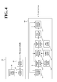
- the robot controller 200 includes an information acquisition section 201, a holding information storage section 202, an operation form determining section 203, a position storage section 204, a distance determining section 205, a time storage section 206, a transfer time calculating section 207, an order determining section 208, and an operation controlling section 209.
- the information acquisition section 201 acquires information indicating the location and posture of each workpiece W output from the image processing section 403 of the image processing apparatus 400.
- the holding information storage section 202 stores information indicating holding operation forms of different kinds of workpieces W of mutually different transfer speeds, and stores, in relation to this information, execution conditions for the holding operation forms.
- the information indicating the holding operation forms of the workpieces W stored in the holding information storage section 202 may not necessarily include a plurality of kinds of forms. It is also possible to include only one kind of form.
- the holding operation form of a workpiece W specifies which position (portion) of the workpiece W to hold and which method (form) to use to hold the workpiece W.
- the holding operation forms are prioritized.
- the holding operation form of highest priority (for example, of highest transfer speed) is as shown in FIG. 5 .
- the operation form specified here is that the fingers 103a of the gripper 103 in closed state are inserted through the through hole 61a of a workpiece W, and then the fingers 103a are turned into open state to grip the workpiece W.
- This holding operation form is specified under such execution conditions that the through hole 61a be detected, and that when the fingers 103a enter the through hole 61a, the gripper 103 including the fingers 103a and the robot main body 100 meet with no interference other than the workpiece W to be gripped.
- the holding operation form of second highest priority (for example, of second highest transfer speed) is as shown in FIG. 6 .
- the operation form specified here is that the fingers 103a of the gripper 103 grip the head 61 of the workpiece W.
- This holding operation form is specified under such an execution condition that the posture of the grippable position of the head 61 cause no interference with the gripper 103 including the fingers 103a and the robot main body 100.
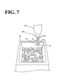
- the holding operation form of third highest priority (for example, of third highest transfer speed) is as shown in FIG. 7 .
- the operation form specified here is that the fingers 103a of the gripper 103 grip the arm 62 of the workpiece W.
- This holding operation form is specified under such an execution condition that the posture of the grippable position of the arm 62 cause no interference with the gripper 103 including the fingers 103a and the robot main body 100.
- holding operation forms and execution conditions are presented for exemplary purposes only; it is also possible to cancel or change at least one of the above-described holding operation forms and execution conditions, or to add some other holding operation form or execution condition to the above-described holding operation forms and execution conditions.
- the operation form determining section 203 acquires information indicating the location and posture of each workpiece W acquired by the information acquisition section 201, and acquires information stored in the holding information storage section 202, namely, the holding operation forms of the plurality of kinds of workpieces W and the execution conditions for the holding operation forms. Then, based on these acquired pieces of information, the operation form determining section 203 determines whether any of the execution conditions for the holding operation forms are satisfied individually for each of the workpieces W. Then, when a workpiece W satisfies any of the execution conditions for the holding operation forms, the operation form determining section 203 determines a holding operation form individually for the workpiece W from among the holding operation forms associated with the satisfied execution condition.
- the determined holding operation form is a highest priority holding operation form among the holding operation forms. When no workpiece W satisfies any of the execution conditions for the holding operation forms, no determination is made as to the holding operation form.
- the position storage section 204 stores position information of the workpiece placement position 30a on the conveyor 30.
- the distance determining section 205 acquires, from among the information acquired by the information acquisition section 201, the information indicating the locations of the workpieces W, and the position information that indicates the workpiece placement position 30a on the conveyor 30 and that is stored in the position storage section 204. Then, based on these acquired pieces of information, the distance determining section 205 calculates an entire transfer distance individually for each of the workpieces W. The entire transfer distance is from the location of each workpiece W to the workpiece placement position 30a. That is, in this embodiment, the sensor unit 300 collectively scans the inner-stocker 20 entire region, and then the distance determining section 205 calculates the entire transfer distances of the workpieces W located in the inner-stocker 20 entire region at a time.
- the time storage section 206 stores information indicating, for each of the holding operation forms, transfer time per predetermined unit transfer distance over which the workpiece W is transferred by the robot main body 100.
- the transfer time calculating section 207 acquires: information indicating the entire transfer distances of the workpieces W calculated by the distance determining section 205; information indicating the holding operation forms of the workpieces W determined by the operation form determining section 203; and information stored in the time storage section 206 for each of the holding operation forms, namely, the transfer time per predetermined unit transfer distance over which the workpiece W is transferred. Then, based on these acquired pieces of information, the transfer time calculating section 207 calculates (estimates) the transfer time individually for each of the workpieces W transferred by the robot main body 100.
- the order determining section 208 determines the transfer order of the workpieces W. More specifically, the order determining section 208 determines the transfer order so that every one set of (four) workpieces W, which is collectively processed in the post-processing step, has approximately uniform transfer time. There is no particular limitation to the method by which the order determining section 208 determines the transfer order. Examples include the following methods.
- the order determining section 208 calculates average transfer time of one workpiece W. Then, based on the calculated average transfer time of one workpiece W, the order determining section 208 calculates average transfer time of one set (four workpieces W). Then, the order determining section 208 combines the workpieces W into sets (a first set, a second set, a third set, and so forth) of four workpieces W each so as to make the transfer time of each of the sets approximately equal to the above-calculated average transfer time of the one set, so that every set has approximately uniform transfer time. Then, the order determining section 208 determines the transfer order of the sets.
- each set is a mixture of a workpiece W with short transfer time and a workpiece W with long transfer time, or a mixture of workpieces W each with approximately average transfer time.
- the transfer time when viewed on a one-set basis is approximately uniform among the sets.
- FIG. 8 shows an example of the transfer order determined by the above-described method.
- the example in FIG. 8 shows that in the first set, the first and fourth workpieces W have short transfer times, that the second workpiece W has long transfer time, and that the third workpiece W has approximately average transfer time.
- Such first set has transfer time approximately equal to the average transfer time of the one set.
- the second set the first (fifth in total) and fourth (eighth in total) workpieces W have long transfer times, and the second (sixth in total) and third (seventh in total) workpieces W have short transfer times.
- Such second set has transfer time that is slightly shorter than the transfer time of the first set; nevertheless, the transfer time is still approximately equal to the average transfer time of the one set.
- the first to fourth (ninth to twelfth in total) workpieces W have approximately average transfer times.
- Such third set have transfer time that is slightly longer than the transfer time of the first set; nevertheless, the transfer time is still approximately equal to the average transfer time of the one set.
- the forth and later sets, which are not shown and not elaborated, each have transfer time approximately equal to the average transfer time of the one set, similarly to the first to third sets.
- the transfer time when viewed on a one-set basis is approximately uniform among the sets.
- the operation controlling section 209 acquires information indicating the location and posture of each workpiece W acquired by the information acquisition section 201, information indicating the holding operation form of each workpiece W determined by the operation form determining section 203, and information indicating the transfer order determined by the order determining section 208. Then, based on these acquired pieces of information, the operation controlling section 209 generates an operation signal for the servo motors of the arm 102 and the actuator of the gripper 103 so as to transfer each workpiece W in accordance with the transfer order determined by the order determining section 208 while gripping the workpiece W in the holding operation form determined by the operation form determining section 203. Then, the operation controlling section 209 outputs the generated operation signal to the servo motors of the arm 102 and to the actuator of the gripper 103, thereby controlling the operations of the arm 102 and the gripper 103 of the robot main body 100.
- the image processing apparatus 400 has its signal acquisition section 401 acquire the detection signal.
- the image processing apparatus 400 has its image processing section 403 individually recognize the workpieces W located in the inner-stocker 20 entire region scanned by the sensor unit 300 based on the three-dimensional shape information of the workpieces W stored in the workpiece shape storage section 402 and based on the detection signal acquired at step S10, while at the same time detecting the locations and postures of the recognized workpieces W. Then, the image processing apparatus 400 has its image processing section 403 output information indicating the detected location and posture of each workpiece W to the robot controller 200.
- the robot controller 200 has its information acquisition section 201 acquire the information that indicates the location and posture of each workpiece W and that has been output from the image processing section 403 at step S20.
- the robot controller 200 has its operation form determining section 203 acquire the information that indicates the location and posture of each workpiece W and that has been acquired at step S30, and acquire information stored in the holding information storage section 202, namely, the holding operation forms of the plurality of kinds of workpieces W and the execution conditions for the holding operation forms. Then, based on these acquired pieces of information, the robot controller 200 has its operation form determining section 203 determine whether any of the execution conditions for the holding operation forms are satisfied individually for each of the workpieces recognized at step S20.
- the robot controller 200 has its operation form determining section 203 determine a holding operation form individually for the workpiece W from among the holding operation forms associated with the satisfied execution condition.
- the determined holding operation form is a highest priority holding operation form among the holding operation forms.
- step S50 the robot controller 200 determines whether a holding operation form has been determined at step S40.
- the determination at step S50 is not in the affirmative, and the processings illustrated on this flow end. It should be noted, however, that when there are still some workpieces W left, the robot main body 100 may perform a derangement operation with respect to these workpieces W as necessary, after which similar processings may be executed again back at step S10.
- the derangement operation which is described in detail in, for example, Japanese Unexamined Patent Application Publication No. 2011- 183537 , will not be elaborated here.
- the determination at step S50 is in the affirmative, and the flow proceeds to step S60.
- the robot controller 200 has its distance determining section 205 acquire, from among the information acquired at step S30, the information indicating the locations of the workpieces W, and the position information that indicates the workpiece placement position 30a on the conveyor 30 and that is stored in the position storage section 204. Then, based on these acquired pieces of information, the robot controller 200 has its distance determining section 205 calculate an entire transfer distance individually for each of the workpieces W. The entire transfer distance is from the location of each workpiece W to the workpiece placement position 30a.
- the robot controller 200 has its transfer time calculating section 207 acquire: information indicating the entire transfer distance of each workpiece W calculated at step S60; information indicating the holding operation form of each workpiece W determined at step S40; and information stored in the time storage section 206 for each of the holding operation forms, namely, the transfer time per predetermined unit transfer distance over which the workpiece W is transferred. Then, based on these acquired pieces of information, the robot controller 200 has its transfer time calculating section 207 calculate the transfer time individually for each of the workpieces W transferred by the robot main body 100.
- the robot controller 200 has its order determining section 208 determine, based on the transfer time of each of the workpieces W calculated at step S70, the transfer order so that every one set of (four) workpieces W, which is collectively processed in the post-processing step, has approximately uniform transfer time.
- the robot controller 200 has its operation controlling section 209 acquire the information that indicates the location and posture of each workpiece W and that has been acquired at step S30, information indicating the holding operation form of each workpiece W determined at step S40, and information indicating the transfer order determined at step S80. Then, based on these acquired pieces of information, the robot controller 200 has its operation controlling section 209 control operations of the arm 102 and the gripper 103 of the robot main body 100 so as to transfer each workpiece W in accordance with the transfer order determined at step S80 while gripping the workpiece W in the holding operation form determined at step S40. Then, similar processings are executed again back at step S10.
- the robot main body 100 includes the arm 102 and the gripper 103, and the arm 102 and the gripper 103 transfer, in order, a plurality of workpieces W to be processed on a four-workpieces W basis.
- the plurality of workpieces W are arranged at positions of a variety of different distances from the robot main body 100.
- the distances vary from the locations of the workpieces W to their transfer destination, namely, the workpiece placement position 30a on the conveyor 30.
- the distance determining section 205 calculates, for each of the plurality of workpieces W, the entire transfer distance from the location of each workpiece W to the workpiece placement position 30a. Then, based on the calculation result, the order determining section 208 determines the transfer order of the workpieces W so that every set of four workpieces W has uniform transfer time. Then, the arm 102 and the gripper 103 perform transfer work in the order determined by the control performed by the operation controlling section 209. Thus, the transfer time when viewed on a four-workpieces W basis is approximately uniform among the sets. This ensures smooth transfer work as opposed to the above-described situation in which the transfer work makes uneven progress in time.
- the transfer time calculating section 207 calculates the transfer time of each workpiece W. Then, based on the transfer time of each workpiece W calculated by the transfer time calculating section 207, the order determining section 208 determines the transfer order of the workpieces W so that every set of four workpieces W has uniform transfer time. Calculating the transfer time of each of the workpieces W and determining their order using the calculated transfer time in the above-described manner ensure reliable, smooth transfer work with improved accuracy.
- the distance determining section 205 collectively calculates the entire transfer distances of the workpieces W. Collectively calculating the entire transfer distances of the workpieces W in this manner shortens the time necessary for the distance calculation processing, which in turn shortens the entire transfer time.
- this embodiment provides the following advantageous effects.
- the image processing section 403 detects the posture of each of the workpieces W.
- the transfer time calculating section 207 calculates the transfer time of each of the workpieces W not only in accordance with the entire transfer distance but also in accordance with the posture of each workpiece W. This provides a correction to the elongated transfer time caused by posture, ensuring smooth transfer work with improved accuracy.
- the order determining section 208 determines the transfer order of the workpieces W so that uniform transfer time is ensured for every set of four workpieces W, which is collectively processed in the predetermined post-processing step after the workpieces W have been transferred. This ensures efficient processing performed after the transfer work of the workpieces W has been done, with no or minimal congestion and time loss associated with forwarding the workpieces W to the post-processing step.
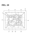
- the laser scanner 301 of the sensor unit 300 uses a mirror to reflect laser slit light generated by the laser light source, and uses a motor to rotate the mirror, thereby radiating from above laser slit light to the sub-regions Ar1 to Ar9 as a unit of radiation. In this manner, the laser scanner 301 scans the workpieces W located in the sub-regions Ar1 to Ar9 as a unit of scanning.
- the reflected objects located in one sub-region reflect the laser slit light, which results in reflection light of the laser slit light.
- the camera 302 of the sensor unit 300 uses an image pick-up device to pick up an image of the reflection light of the laser slit light. That is, the camera 302 has its image pick-up device pick up an image (grayscale image) from above the one sub-region, and an image of the reflection light of the laser slit light reflected by the reflected objects located in the sub-region.
- the sensor controller 310 of the sensor unit 300 detects the distance to the reflected objects located in the one sub-region. Then, the sensor controller 310 outputs to the image processing apparatus 400 a detection signal as a detection result of the sensor unit 300.
- the detection signal includes the image picked up from above the one sub-region, and distance information that is indicated on this image and that corresponds to the detected distance to the reflected objects located in the one sub-region.
- the image processing apparatus 400 individually recognizes (measures three-dimensionally) the workpieces W located in the sub-region that has been scanned by the sensor unit 300.
- FIG. 11 corresponds to FIG. 4 .
- the elements equivalent to those in FIG. 4 are designated the same reference numerals as in FIG. 4 , and description of these elements will be omitted.
- a robot controller 200 includes the information acquisition section 201, the holding information storage section 202, the operation form determining section 203, the position storage section 204, a range information storage section 210, a distance determining section 205', an order determining section 208', and an operation controlling section 209'.
- the range information storage section 210 stores range information (position information) of the sub-regions Ar1 to Ar9 of the inner-stocker 20 entire region.
- the distance determining section 205' acquires the range information of the sub-regions Ar1 to Ar9 stored in the range information storage section 210, and the position information that indicates the workpiece placement position 30a on the conveyor 30 and that is stored in the position storage section 204. Then, based on these acquired pieces of information, the distance determining section 205' assumes the entire transfer distance of each workpiece W located in each of the sub-regions Ar1 to Ar9 as the distance from a predetermined position (for example, center position) of each of the sub-regions Ar1 to Ar9 to the workpiece placement position 30a (the distance being hereinafter referred to as assumed entire transfer distance), and calculates the assumed entire transfer distance.
- assumed entire transfer distance the distance being hereinafter referred to as assumed entire transfer distance
- the order determining section 208' determines the order of the sub-regions Ar1 to Ar9 from which to transfer the workpieces W. More specifically, the order determining section 208' determines the order of the sub-regions Ar1 to Ar9 from which to transfer the workpieces W so that every set of (four) workpieces W, which is collectively processed in the above-described post-processing step, has approximately uniform transfer time.
- the phrase "determining the order of the sub-regions Ar1 to Ar9 from which to transfer the workpieces W" can be rephrased as "determining the transfer order of the workpieces W".
- the operation controlling section 209' acquires information indicating the order that is associated with the plurality of sub-regions Ar1 to Ar9 from which to transfer the workpieces W and that has been determined by the order determining section 208'. Then, based on the acquired information, the operation controlling section 209' generates an operation signal for the sensor controller 310 so as to cause the sensor unit 300 to scan the plurality of sub-regions Ar1 to Ar9 in accordance with the order determined by the order determining section 208'. Then, the operation controlling section 209' outputs the generated operation signal to the sensor controller 310, thereby controlling an operation of the sensor unit 300.
- the operation controlling section 209' also acquires information indicating the location and posture of each workpiece W acquired by the information acquisition section 201, and information indicating the holding operation form of each workpiece W determined by the operation form determining section 203. Then, the operation controlling section 209' generates an operation signal for the servo motors of the arm 102 and the actuator of the gripper 103 so as to transfer the workpieces W located in the sub-regions scanned by the sensor unit 300 in accordance with the order determined by the order determining section 208' and in the holding operation forms determined by the operation form determining section 203.
- the operation controlling section 209' outputs the generated operation signal to the servo motors of the arm 102 and to the actuator of the gripper 103, thereby controlling the operations of the arm 102 and the gripper 103 of the robot main body 100.
- the phrase “controlling the operations of the arm 102 and the gripper 103 so as to transfer the workpieces W located in the scanned sub-regions in accordance with the order determined by the order determining section 208'" can be rephrased as "controlling the operations of the arm 102 and the gripper 103 so as to transfer the workpieces W in accordance with the order determined by the order determining section 208'".
- An image processing apparatus 400 includes the signal acquisition section 401, the workpiece shape storage section 402, and an image processing section 403'.
- the image processing section 403' performs the above-described image processing based on the three-dimensional shape information of the workpieces W stored in the workpiece shape storage section 402 and based on the detection signal acquired by the signal acquisition section 401. In this manner, the image processing section 403' individually recognizes the workpieces W located in the sub-regions scanned by the sensor unit 300. At the same time, the image processing section 403' detects the location and posture of each of the recognized workpieces W. Then, the image processing section 403' outputs information indicating the location and posture of each detected workpiece W to the robot controller 200.
- the robot controller 200 has its distance determining section 205' acquire the range information of the sub-regions Ar1 to Ar9 stored in the range information storage section 210, and the position information that indicates the workpiece placement position 30a on the conveyor 30 and that is stored in the position storage section 204. Then, based on these acquired pieces of information, the robot controller 200 has its distance determining section 205' assume the assumed entire transfer distance of each of the sub-regions Ar1 to Ar9 as the entire transfer distance of each workpiece W located in each of the sub-regions Ar1 to Ar9, and calculate the assumed entire transfer distance.
- the robot controller 200 has its order determining section 208' acquire information indicating the assumed entire transfer distance of each of the sub-regions Ar1 to Ar9 calculated at step S110 under the assumption of the entire transfer distance of each workpiece W located in each of the sub-regions Ar1 to Ar9. Then, based on the acquired information, the robot controller 200 has its order determining section 208' determine the order of the sub-regions Ar1 to Ar9 from which to transfer the workpieces W so that every set of (four) workpieces W, which is collectively processed in the post-processing step, has approximately uniform transfer time.
- the robot controller 200 has its operation controlling section 209' acquire information that indicates the order of the sub-regions from which to transfer the workpieces W and that has been determined at step S120. Then, based on the acquired information, the robot controller 200 has its operation controlling section 209' output an operation signal to the sensor controller 310 so as to cause the sensor unit 300 to scan the sub-regions Ar1 to Ar9 in accordance with the order determined at step S120.
- the sensor controller 310 outputs a detection signal to the image processing apparatus 400, and at step S 140, the image processing apparatus 400 has its signal acquisition section 401 acquire the detection signal.
- the image processing apparatus 400 has its image processing section 403' individually recognize the workpieces W located in the sub-regions scanned by the sensor unit 300 based on the three-dimensional shape information of the workpieces W stored in the workpiece shape storage section 402 and based on the detection signal acquired at step S140, while at the same time detecting the locations and postures of the recognized workpieces W. Then, the image processing apparatus 400 has its image processing section 403 output to the robot controller 200 information indicating the detected location and posture of each workpiece W.
- the robot controller 200 has its information acquisition section 201 acquire the information indicating the location and posture of each workpiece W output from the image processing section 403 at step S150.
- the robot controller 200 has its operation form determining section 203 acquire the information that indicates the location and posture of each workpiece W and that has been acquired at step S160, and acquire information stored in the holding information storage section 202, namely, information indicating the holding operation forms of the plurality of kinds of workpieces W and the execution conditions for the holding operation forms. Then, based on these acquired pieces of information, the robot controller 200 has its operation form determining section 203 determine a particular workpiece W, among the workpieces recognized at step S 150, as a workpiece W to be transferred when the particular workpiece W satisfies any of the execution conditions for the holding operation forms (for example, easiest workpiece W to grip), and determine the holding operation form of the workpiece W. When no workpiece W satisfies any of the execution conditions for the holding operation forms, no determination is made as to the workpiece W to be transferred.
- step S 180 the robot controller 200 determines whether the workpiece W to be transferred has been determined at step S 170.
- the determination at step S 180 is not in the affirmative, and the processings illustrated on this flow end. It should be noted, however, that when there are still some workpieces W left, the robot main body 100 may perform a derangement operation with respect to these workpieces W as necessary, after which similar processings may be executed again back at step S 140.
- the determination at step S 180 is in the affirmative, and the flow proceeds to step S 190.
- the robot controller 200 has its operation controlling section 209' acquire the workpiece W that is to be transferred and has been determined at step S 180 and information indicating the holding operation form of the workpiece W. Then, based on these acquired pieces of information, the robot controller 200 has its operation controlling section 209' control operations of the arm 102 and the gripper 103 of the robot main body 100 so as to transfer the workpiece W determined to be transferred at step S 180 while gripping the workpiece W in the holding operation form determined simultaneously with the workpiece W. Then, similar processings are executed again back at step S 140.
- the workpieces W transferred at step S 190 are the workpieces W located in the sub-regions scanned in accordance with the order determined at step S120.
- the operation controlling section 209' can be viewed as controlling the operations of the arm 102 and the gripper 103 so as to transfer the workpieces W located in the sub-regions Ar1 to Ar9 in accordance with the order determined at step S120.
- the distance determining section 205' divides the region in which all the workpieces W are disposed into nine sub-regions Ar1 to Ar9, assumes the entire transfer distance of each workpiece W located in each of the sub-regions Ar1 to Ar9 as the distance from a predetermined position in each of the sub-regions Ar1 to Ar9 to the workpiece placement position 30a, and calculates this distance. This ensures a simpler method of calculating the entire transfer distance of each workpiece W.
- the sensor unit 300 is provided to detect the locations of each of the workpieces W in the horizontal direction and the vertical direction, and based on a detection result of the sensor unit 300, the distance determining section 205 of the robot controller 200 calculates the entire transfer distance of each of the workpieces W from the location of each workpiece W to the workpiece placement position 30a on the conveyor 30.
- This example should not be construed as limiting the present invention.
- Other examples include the case of a constant vertical height from the installation position of the robot main body 100 to the disposed surfaces of all the workpieces W.
- a sensor is provided to detect the location of each workpiece W in the horizontal direction. Then, based on a detection result of the sensor, the distance determining section of the robot controller 200 calculates the horizontal distance from the location of each workpiece W to the workpiece placement position 30a. Then, the distance determining section may determine the entire transfer distance by adding the above-described vertical height to the calculated horizontal distance from the location of each workpiece W to the workpiece placement position 30a.
- the vertical height corresponds to the vertical transfer distance from the location of each workpiece W to the workpiece placement position 30a, and is fixed in advance.
- the image processing section 403 detects both the location and posture of each workpiece W, and outputs information indicating both the location and posture of each workpiece W.
- the image processing section may detect the location of each workpiece W alone and output information indicating the location of the workpiece W alone.
- the transfer time calculating section 207 calculates the transfer time of each workpiece W based on the entire transfer distance of the workpiece W determined based on the location of the workpiece W.
- the order determining section 208 determines the transfer order of the workpieces W based on the transfer time of each of the workpieces W calculated by the transfer time calculating section 207.
- the transfer time calculating section 207 may be omitted, and the order determining section may determine the transfer order of the workpieces W based on the calculation result of the distance determining section 205.
- the sensor unit 300 includes the laser scanner 301 and the camera 302 to detect the location of each workpiece W and other parameters.
- This example should not be construed as limiting the present invention. It is also possible to use a sensor of a format different from the above-described format to detect the location of each workpiece W and other parameters.
- the image processing apparatus 400 detects the location of each workpiece W and other parameters.
- This example should not be construed as limiting the present invention.
- the robot apparatus 10 is applied to transfer of a plurality of workpieces W in order.
- This example should not be construed as limiting the present invention.
- the robot apparatus 10 may be applied to collection processing involving transfer of a plurality of workpieces W in order.
- FIGs. 4 and 11 indicate exemplary signal flows and should not be construed as limiting the signal flow directions.
Landscapes
- Engineering & Computer Science (AREA)
- Robotics (AREA)
- Mechanical Engineering (AREA)
- Manipulator (AREA)
Applications Claiming Priority (1)
| Application Number | Priority Date | Filing Date | Title |
|---|---|---|---|
| JP2012202920A JP5614553B2 (ja) | 2012-09-14 | 2012-09-14 | ロボット装置 |
Publications (1)
| Publication Number | Publication Date |
|---|---|
| EP2708333A2 true EP2708333A2 (fr) | 2014-03-19 |
Family
ID=48915852
Family Applications (1)
| Application Number | Title | Priority Date | Filing Date |
|---|---|---|---|
| EP13178340.9A Withdrawn EP2708333A2 (fr) | 2012-09-14 | 2013-07-29 | Appareil de robot pour transférer des objets à traiter |
Country Status (4)
| Country | Link |
|---|---|
| US (1) | US9102063B2 (fr) |
| EP (1) | EP2708333A2 (fr) |
| JP (1) | JP5614553B2 (fr) |
| CN (1) | CN103659822B (fr) |
Cited By (3)
| Publication number | Priority date | Publication date | Assignee | Title |
|---|---|---|---|---|
| CN105666494A (zh) * | 2016-04-09 | 2016-06-15 | 王玮 | 机器人控制方法以及机器人系统 |
| EP3258762A4 (fr) * | 2015-02-12 | 2018-02-21 | Fuji Machine Mfg. Co., Ltd. | Dispositif d'introduction de composants |
| US10434652B2 (en) | 2017-05-19 | 2019-10-08 | Fanuc Corporation | Workpiece picking system |
Families Citing this family (19)
| Publication number | Priority date | Publication date | Assignee | Title |
|---|---|---|---|---|
| JPWO2016046897A1 (ja) * | 2014-09-23 | 2017-06-29 | 富士機械製造株式会社 | 部品供給システム |
| JP6728647B2 (ja) * | 2015-11-25 | 2020-07-22 | 株式会社ジェイテクト | 搬送装置 |
| JP6744709B2 (ja) * | 2015-11-30 | 2020-08-19 | キヤノン株式会社 | 情報処理装置、情報処理方法 |
| CN106269548A (zh) * | 2016-09-27 | 2017-01-04 | 深圳市创科智能技术有限公司 | 一种物体自动分拣方法及其装置 |
| DE112017007397B4 (de) | 2017-04-04 | 2021-09-30 | Mujin, Inc. | Steuervorrichtung, Greifsystem, Verteilersystem, Programm, Steuerverfahren und Herstellungsverfahren |
| DE112017007392B4 (de) | 2017-04-04 | 2021-11-04 | Mujin, Inc. | Steuervorrichtung, Greifsystem, Verteilersystem, Programm, Steuerverfahren und Herstellungsverfahren |
| CN115385039A (zh) | 2017-04-04 | 2022-11-25 | 牧今科技 | 控制装置、信息处理装置、控制方法以及信息处理方法 |
| DE112017007394B4 (de) | 2017-04-04 | 2020-12-03 | Mujin, Inc. | Informationsverarbeitungsvorrichtung, Greifsystem, Verteilersystem, Programm und Informationsverarbeitungsverfahren |
| JP6444499B1 (ja) | 2017-04-04 | 2018-12-26 | 株式会社Mujin | 制御装置、ピッキングシステム、物流システム、プログラム、及び、制御方法 |
| JP6931457B2 (ja) * | 2017-07-14 | 2021-09-08 | オムロン株式会社 | モーション生成方法、モーション生成装置、システム及びコンピュータプログラム |
| JP7062406B2 (ja) * | 2017-10-30 | 2022-05-16 | 株式会社東芝 | 情報処理装置及びロボットアーム制御システム |
| JP2019084601A (ja) * | 2017-11-02 | 2019-06-06 | キヤノン株式会社 | 情報処理装置、把持システムおよび情報処理方法 |
| JP7035467B2 (ja) * | 2017-11-13 | 2022-03-15 | 株式会社Ihi | 加工装置 |
| JP7065886B2 (ja) * | 2017-12-28 | 2022-05-12 | 株式会社Fuji | 情報提供装置、情報提供方法及びプログラム |
| JP7418743B2 (ja) * | 2019-05-21 | 2024-01-22 | 株式会社別川製作所 | 対象ワークの識別移載装置及び識別移載方法 |
| US10906188B1 (en) * | 2019-10-25 | 2021-02-02 | Dexterity, Inc. | Singulation of arbitrary mixed items |
| JP7612193B2 (ja) * | 2020-12-28 | 2025-01-14 | 東京ロボティクス株式会社 | 動作スケジュール生成装置、方法、プログラム及びシステム |
| US12319517B2 (en) | 2021-03-15 | 2025-06-03 | Dexterity, Inc. | Adaptive robotic singulation system |
| US12129132B2 (en) | 2021-03-15 | 2024-10-29 | Dexterity, Inc. | Singulation of arbitrary mixed items |
Citations (2)
| Publication number | Priority date | Publication date | Assignee | Title |
|---|---|---|---|---|
| JP2001300878A (ja) | 2000-04-19 | 2001-10-30 | Daihatsu Motor Co Ltd | パレット内バラ積みワークの取出方法 |
| JP2011183537A (ja) | 2010-03-11 | 2011-09-22 | Yaskawa Electric Corp | ロボットシステム及びロボット装置並びにワーク取り出し方法 |
Family Cites Families (15)
| Publication number | Priority date | Publication date | Assignee | Title |
|---|---|---|---|---|
| US4437114A (en) * | 1982-06-07 | 1984-03-13 | Farrand Optical Co., Inc. | Robotic vision system |
| US5041907A (en) * | 1990-01-29 | 1991-08-20 | Technistar Corporation | Automated assembly and packaging system |
| US5040056A (en) * | 1990-01-29 | 1991-08-13 | Technistar Corporation | Automated system for locating and transferring objects on a conveyor belt |
| JPH04183583A (ja) * | 1990-11-19 | 1992-06-30 | Nippon Telegr & Teleph Corp <Ntt> | 製品製造方式 |
| JP4303411B2 (ja) * | 2000-10-06 | 2009-07-29 | セイコーインスツル株式会社 | トラッキング方法、及びトラッキングシステム |
| JP2005052941A (ja) * | 2003-08-05 | 2005-03-03 | Fanuc Ltd | ワーク載置装置 |
| JP2005111607A (ja) * | 2003-10-07 | 2005-04-28 | Fanuc Ltd | ロボット物流トラッキング装置 |
| JP4864363B2 (ja) * | 2005-07-07 | 2012-02-01 | 東芝機械株式会社 | ハンドリング装置、作業装置及びプログラム |
| JP4199264B2 (ja) * | 2006-05-29 | 2008-12-17 | ファナック株式会社 | ワーク取り出し装置及び方法 |
| JP2010115723A (ja) * | 2008-11-11 | 2010-05-27 | Seiko Epson Corp | ロボット及びロボットシステム |
| JP5402697B2 (ja) * | 2009-10-26 | 2014-01-29 | 株式会社安川電機 | ロボット装置及びワーク取り出しシステム並びにワーク取り出し方法 |
| JP5606145B2 (ja) * | 2010-05-12 | 2014-10-15 | キヤノン株式会社 | ワーク搬送システム |
| JP5382621B2 (ja) * | 2010-06-03 | 2014-01-08 | 株式会社安川電機 | 移載装置 |
| JP4938115B2 (ja) * | 2010-07-27 | 2012-05-23 | ファナック株式会社 | ワーク取出し装置およびワーク取出し方法 |
| DE112011103794B4 (de) * | 2010-11-17 | 2019-01-24 | Mitsubishi Electric Corporation | Aufnehmervorrichtung für Werkstücke |
-
2012
- 2012-09-14 JP JP2012202920A patent/JP5614553B2/ja not_active Expired - Fee Related
-
2013
- 2013-07-29 EP EP13178340.9A patent/EP2708333A2/fr not_active Withdrawn
- 2013-08-01 US US13/956,361 patent/US9102063B2/en not_active Expired - Fee Related
- 2013-09-13 CN CN201310418258.9A patent/CN103659822B/zh not_active Expired - Fee Related
Patent Citations (2)
| Publication number | Priority date | Publication date | Assignee | Title |
|---|---|---|---|---|
| JP2001300878A (ja) | 2000-04-19 | 2001-10-30 | Daihatsu Motor Co Ltd | パレット内バラ積みワークの取出方法 |
| JP2011183537A (ja) | 2010-03-11 | 2011-09-22 | Yaskawa Electric Corp | ロボットシステム及びロボット装置並びにワーク取り出し方法 |
Cited By (5)
| Publication number | Priority date | Publication date | Assignee | Title |
|---|---|---|---|---|
| EP3258762A4 (fr) * | 2015-02-12 | 2018-02-21 | Fuji Machine Mfg. Co., Ltd. | Dispositif d'introduction de composants |
| US11219149B2 (en) | 2015-02-12 | 2022-01-04 | Fuji Corporation | Component supply device |
| CN105666494A (zh) * | 2016-04-09 | 2016-06-15 | 王玮 | 机器人控制方法以及机器人系统 |
| CN105666494B (zh) * | 2016-04-09 | 2017-07-14 | 福州环亚众志计算机有限公司 | 机器人控制方法以及机器人系统 |
| US10434652B2 (en) | 2017-05-19 | 2019-10-08 | Fanuc Corporation | Workpiece picking system |
Also Published As
| Publication number | Publication date |
|---|---|
| US20140081452A1 (en) | 2014-03-20 |
| JP2014058004A (ja) | 2014-04-03 |
| CN103659822A (zh) | 2014-03-26 |
| CN103659822B (zh) | 2015-08-19 |
| JP5614553B2 (ja) | 2014-10-29 |
| US9102063B2 (en) | 2015-08-11 |
Similar Documents
| Publication | Publication Date | Title |
|---|---|---|
| EP2708333A2 (fr) | Appareil de robot pour transférer des objets à traiter | |
| JP7604052B2 (ja) | 箱の開封装置及び箱の開封方法 | |
| CN101291784B (zh) | 用于定位和从载体拾取物体的方法和设备 | |
| US10377581B2 (en) | Article conveying device using at least one sensor | |
| US9415511B2 (en) | Apparatus and method for picking up article randomly piled using robot | |
| JP6273084B2 (ja) | ロボットシステムおよびワークの搬送方法 | |
| EP2783810A2 (fr) | Système de robot et procédé de production d'une pièce à traiter | |
| EP2345515B1 (fr) | Procédé de relever de pièces | |
| EP2899148B1 (fr) | Robot de liaison parallèle, main de robot à liaison parallèle et système de robot de liaison parallèle | |
| EP1816604B1 (fr) | Dispositif de préhension d'une pièce | |
| US20130085604A1 (en) | Robot apparatus, robot system, and method for producing a to-be-processed material | |
| AU2019336263A1 (en) | Vision system for a robotic machine | |
| Nakamoto et al. | High-speed and compact depalletizing robot capable of handling packages stacked complicatedly | |
| JP2013078830A (ja) | ロボットシステムおよび被加工物の製造方法 | |
| EP2711143A2 (fr) | Système de robot et procédé de fabrication d'article | |
| CN108453730B (zh) | 工件取出系统 | |
| EP3260245A1 (fr) | Robot de pliage et procédé de détection de pièce | |
| EP3630417A1 (fr) | Procédé d'étalonnage de transporteur-robot, système de robot et système de commande | |
| US12459131B2 (en) | Picking system | |
| JP4390758B2 (ja) | ワーク取出し装置 | |
| CN110871443B (zh) | 物品取出系统 | |
| JP7436170B2 (ja) | ロボットシステム | |
| CN115003613A (zh) | 用于分离计件货物的设备和方法 | |
| KR20240129578A (ko) | 로봇 시스템, 캘리브레이션 툴 및 캘리브레이션 방법 | |
| JP7362776B2 (ja) | 部品供給装置および部品搬送システム |
Legal Events
| Date | Code | Title | Description |
|---|---|---|---|
| PUAI | Public reference made under article 153(3) epc to a published international application that has entered the european phase |
Free format text: ORIGINAL CODE: 0009012 |
|
| AK | Designated contracting states |
Kind code of ref document: A2 Designated state(s): AL AT BE BG CH CY CZ DE DK EE ES FI FR GB GR HR HU IE IS IT LI LT LU LV MC MK MT NL NO PL PT RO RS SE SI SK SM TR |
|
| AX | Request for extension of the european patent |
Extension state: BA ME |
|
| STAA | Information on the status of an ep patent application or granted ep patent |
Free format text: STATUS: THE APPLICATION HAS BEEN WITHDRAWN |
|
| 18W | Application withdrawn |
Effective date: 20160725 |