EP2708366A2 - Förderungsvorrichtung und Verfahren zur Berechnung des Förderungskorrekturwertes - Google Patents
Förderungsvorrichtung und Verfahren zur Berechnung des Förderungskorrekturwertes Download PDFInfo
- Publication number
- EP2708366A2 EP2708366A2 EP13004447.2A EP13004447A EP2708366A2 EP 2708366 A2 EP2708366 A2 EP 2708366A2 EP 13004447 A EP13004447 A EP 13004447A EP 2708366 A2 EP2708366 A2 EP 2708366A2
- Authority
- EP
- European Patent Office
- Prior art keywords
- conveyance
- sheet
- amount
- state
- roller
- Prior art date
- Legal status (The legal status is an assumption and is not a legal conclusion. Google has not performed a legal analysis and makes no representation as to the accuracy of the status listed.)
- Withdrawn
Links
- 238000012937 correction Methods 0.000 title claims abstract description 114
- 238000000034 method Methods 0.000 title claims description 28
- 238000005259 measurement Methods 0.000 claims description 35
- 238000012360 testing method Methods 0.000 description 39
- 238000011144 upstream manufacturing Methods 0.000 description 13
- 230000007246 mechanism Effects 0.000 description 10
- 230000005540 biological transmission Effects 0.000 description 5
- 229910052751 metal Inorganic materials 0.000 description 5
- 239000002184 metal Substances 0.000 description 5
- 238000012545 processing Methods 0.000 description 5
- WNUUWQUNTSGWGN-UHFFFAOYSA-N 2-(cyclohexylcarbamoyloxy)ethyl 3-acetamido-2,4,6-triiodobenzoate Chemical compound CC(=O)NC1=C(I)C=C(I)C(C(=O)OCCOC(=O)NC2CCCCC2)=C1I WNUUWQUNTSGWGN-UHFFFAOYSA-N 0.000 description 4
- 238000006243 chemical reaction Methods 0.000 description 4
- 238000004519 manufacturing process Methods 0.000 description 4
- 238000004904 shortening Methods 0.000 description 4
- 238000002474 experimental method Methods 0.000 description 3
- 101100438536 Nicotiana plumbaginifolia CABC gene Proteins 0.000 description 2
- 230000009471 action Effects 0.000 description 2
- 230000008859 change Effects 0.000 description 2
- 230000007423 decrease Effects 0.000 description 2
- 230000003247 decreasing effect Effects 0.000 description 2
- 238000001514 detection method Methods 0.000 description 2
- 238000010586 diagram Methods 0.000 description 2
- 230000000694 effects Effects 0.000 description 2
- 230000006870 function Effects 0.000 description 2
- 230000008569 process Effects 0.000 description 2
- 230000009467 reduction Effects 0.000 description 2
- 238000007630 basic procedure Methods 0.000 description 1
- 238000005452 bending Methods 0.000 description 1
- 239000000919 ceramic Substances 0.000 description 1
- 239000011248 coating agent Substances 0.000 description 1
- 238000000576 coating method Methods 0.000 description 1
- 238000007796 conventional method Methods 0.000 description 1
- 238000013461 design Methods 0.000 description 1
- 238000011161 development Methods 0.000 description 1
- 230000018109 developmental process Effects 0.000 description 1
- 230000006872 improvement Effects 0.000 description 1
- 239000007788 liquid Substances 0.000 description 1
- 239000011859 microparticle Substances 0.000 description 1
- 238000012986 modification Methods 0.000 description 1
- 230000004048 modification Effects 0.000 description 1
- 238000000465 moulding Methods 0.000 description 1
- 230000003287 optical effect Effects 0.000 description 1
- 230000000737 periodic effect Effects 0.000 description 1
- 238000003825 pressing Methods 0.000 description 1
- 238000001454 recorded image Methods 0.000 description 1
- 229910052709 silver Inorganic materials 0.000 description 1
- 239000004332 silver Substances 0.000 description 1
- -1 silver halide Chemical class 0.000 description 1
Images





Classifications
-
- B—PERFORMING OPERATIONS; TRANSPORTING
- B41—PRINTING; LINING MACHINES; TYPEWRITERS; STAMPS
- B41J—TYPEWRITERS; SELECTIVE PRINTING MECHANISMS, i.e. MECHANISMS PRINTING OTHERWISE THAN FROM A FORME; CORRECTION OF TYPOGRAPHICAL ERRORS
- B41J13/00—Devices or arrangements of selective printing mechanisms, e.g. ink-jet printers or thermal printers, specially adapted for supporting or handling copy material in short lengths, e.g. sheets
- B41J13/0009—Devices or arrangements of selective printing mechanisms, e.g. ink-jet printers or thermal printers, specially adapted for supporting or handling copy material in short lengths, e.g. sheets control of the transport of the copy material
-
- B—PERFORMING OPERATIONS; TRANSPORTING
- B41—PRINTING; LINING MACHINES; TYPEWRITERS; STAMPS
- B41J—TYPEWRITERS; SELECTIVE PRINTING MECHANISMS, i.e. MECHANISMS PRINTING OTHERWISE THAN FROM A FORME; CORRECTION OF TYPOGRAPHICAL ERRORS
- B41J11/00—Devices or arrangements of selective printing mechanisms, e.g. ink-jet printers or thermal printers, for supporting or handling copy material in sheet or web form
- B41J11/36—Blanking or long feeds; Feeding to a particular line, e.g. by rotation of platen or feed roller
- B41J11/42—Controlling printing material conveyance for accurate alignment of the printing material with the printhead; Print registering
- B41J11/46—Controlling printing material conveyance for accurate alignment of the printing material with the printhead; Print registering by marks or formations on the paper being fed
-
- B—PERFORMING OPERATIONS; TRANSPORTING
- B41—PRINTING; LINING MACHINES; TYPEWRITERS; STAMPS
- B41J—TYPEWRITERS; SELECTIVE PRINTING MECHANISMS, i.e. MECHANISMS PRINTING OTHERWISE THAN FROM A FORME; CORRECTION OF TYPOGRAPHICAL ERRORS
- B41J13/00—Devices or arrangements of selective printing mechanisms, e.g. ink-jet printers or thermal printers, specially adapted for supporting or handling copy material in short lengths, e.g. sheets
- B41J13/0009—Devices or arrangements of selective printing mechanisms, e.g. ink-jet printers or thermal printers, specially adapted for supporting or handling copy material in short lengths, e.g. sheets control of the transport of the copy material
- B41J13/0027—Devices or arrangements of selective printing mechanisms, e.g. ink-jet printers or thermal printers, specially adapted for supporting or handling copy material in short lengths, e.g. sheets control of the transport of the copy material in the printing section of automatic paper handling systems
Definitions
- aspects of the present invention generally relate to a configuration and control of a conveyance apparatus in a recording apparatus which causes a conveyance unit to pinch and convey a recording medium to perform a recording operation.
- an image forming apparatus such as a copying machine or a printer has many opportunities to print a photographic image.
- an image can be formed in a quality equal to that of a silver halide photograph because of smaller liquid droplets of ink or an improvement in an image processing technique.
- the demand accuracy of a mechanism part in a recording apparatus is very high in the context of the demand for the high image quality.
- a conveyance amount of the recording medium is approximately proportional to an outer diameter of the roller which conveys the recording medium. Very high accuracy is thus demanded for the roller.
- the processing accuracy of the part has its limit, and the accuracy enhancement of the part causes an increase in a manufacturing cost, there is need for a technique for executing high-quality image recording without depending on the accuracy of the part.
- a main recording unit of a recording apparatus includes a recording head, and a plurality of conveyance rollers provided on an upstream side or a downstream side of the recording head. While the recording medium is held and conveyed by the plurality of conveyance rollers, recording is performed on the recording medium by the recording head. A conveyance amount of a recording medium is changed according to a conveyance condition such as switching of a roller which conveys the recording medium in the conveyance of the recording medium in the recording apparatus. Consequently, it is necessary to correct the conveyance amount according to each conveyance condition to execute the high-quality image recording over the entire region of the recording medium.
- Japanese Patent Application Laid-Open No. 2008-30455 discusses a method for correcting conveyance of a recording medium in order to correspond to the above-described issue.
- the method records a pattern on a sheet, reads the recorded pattern to actually measure a conveyance amount, and performs correction using a correction value calculated from the actual measured value.
- a technique is discussed which shifts a nozzle to be used to a conveyance downstream side at the timing at which a trailing edge of a recording medium comes off from a conveyance roller located on an upstream side of a conveyance direction to a recording head in order to record as many patterns as possible over the entire region of the recording medium.
- the technique for correcting the conveyance of the recording medium, involving the reading of the pattern it is also necessary to consider shortening of a measurement time involving the actual measurement of the conveyance amount in addition to highly accurate correction of each conveyance condition. If the measurement time is longer, for example, when actual measurement is performed at the site where an apparatus is manufactured, such as in a factory, a time related to the manufacture of the apparatus is longer, which accordingly leads to an increase in a manufacturing cost. Even when actual measurement is performed in a user's site, the user may feel stress about the length of the measurement time. Therefore, it is important that the correction can be performed with high accuracy in a measurement time which is as short as possible.
- aspects of the present invention are generally directed to a reduction in labor and time for actual measurement of a conveyance amount for obtaining a correction value for conveyance.
- a conveyance apparatus as specified in claim 1.
- a conveyance apparatus as specified in claim 2.
- a conveyance apparatus as specified in claim 3.
- a recording apparatus as specified in claim 9.
- a method for calculating a correction for conveyance of a conveyance apparatus as specified in claim 10.
- the labor and time for actual measurement of the conveyance amount for obtaining the correction value for conveyance can be reduced.
- Fig. 1 is a perspective view of a mechanism unit in a recording apparatus according to a first exemplary embodiment.
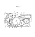
- Fig. 2 is a side view particularly illustrating a conveyance mechanism including a sheet conveyance unit in the recording apparatus according to the first exemplary embodiment.
- Fig. 3 is a perspective view particularly illustrating the conveyance mechanism including the sheet conveyance unit in the recording apparatus according to the first exemplary embodiment.
- Figs. 4A to 4C are schematic cross-sectional views illustrating a change in a state of a conveyance operation when an image is recorded in the recording apparatus according to the first exemplary embodiment.
- Fig. 5 is a control block diagram of the recording apparatus according to the first exemplary embodiment.
- Fig. 6 illustrates an example of test patterns for actually measuring a conveyance amount in each conveyance state in the recording apparatus according to the first exemplary embodiment.
- Fig. 7 illustrates a control flowchart for correcting a conveyance amount at the time of a recording operation in the recording apparatus according to the first exemplary embodiment.
- Fig. 8 is a schematic sectional view particularly illustrating a conveyance mechanism including a sheet conveyance unit in a recording apparatus according to a second exemplary embodiment.
- Fig. 9 illustrates a relationship between a load and a conveyance amount when a recording medium is conveyed.
- Fig. 10 is a table which stores conveyance-amount correction values and values required for calculating the conveyance-amount correction values in respective conveyance states according to the first exemplary embodiment.
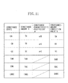
- Fig. 11 is a table which stores conveyance-amount correction values and values required for calculating the conveyance-amount correction values in respective conveyance states according to the second exemplary embodiment.
- Fig. 1 is a perspective view of a mechanism unit of a recording apparatus according to a first exemplary embodiment.
- a recording unit records an image on a recording medium, which is a sheet, by a recording head 7 mounted on a carriage 50.
- An image based on recording image information is recorded by ink discharged from the recording head 7 located above the recording medium.
- the carriage 50 on which the recording head 7 and an ink tank 71 for supplying ink to the recording head 7 are mounted is movable in a scanning direction which intersects a conveyance direction indicated by X in Fig. 1 .
- the carriage 50 performs image recording in a width direction of the recording medium while moving in the scanning direction.
- the sheet conveyance unit is disposed on a downstream side in the conveyance direction of a sheet feeding unit 21, and conveys recording media separated one by one and fed, with high accuracy.
- the main mechanism of the sheet conveyance unit is attached to a chassis 11 formed by bending a sheet metal and chassis 97 and 98 formed by molding.
- the recording medium is conveyed by a conveyance roller 36 and a discharge roller 40, which is described below.
- the conveyance roller 36 and the discharge roller 40 respectively correspond to a first conveyance roller and a second conveyance roller according to the present embodiment.
- the conveyance roller 36 is formed by coating a surface of a metal shaft with ceramic micro-particles, and includes metal portions at the ends thereof.
- the metal portions of the conveyance roller 36 are supported by bearing portions attached to the chassis 97 and 98.
- a plurality of pinch rollers 37 are held by a pinch roller holder 30 and are urged against a surface of the conveyance roller 36 by a pinch roller spring 31.
- the pinch rollers 37 are in contact with the surface of the conveyance roller 36, and are rotated by the rotation of the conveyance roller 36.
- Figs. 2 and 3 are a side view and a perspective view particularly illustrating a conveyance mechanism including the sheet conveyance unit in the recording apparatus according to the present exemplary embodiment.
- the conveyance roller 36 receives a rotational force when a driving force of a conveyance motor 35, which is a direct current (DC) motor, is transmitted to a pulley gear 361 provided on a shaft of the conveyance roller 36 via a timing belt 39.
- a code wheel 362 in which slits are formed at a pitch of 150 lpi to 360 lpi is directly connected to the conveyance roller 36 such that the code wheel 362 is coaxial with the conveyance roller 36.
- a conveyance-roller encoder sensor 363 is fixed to the chassis 98 at a position illustrated in Fig.
- the conveyance-roller encoder sensor 363 counts the number of the slits on the code wheel 362 to manage rotation amounts of the conveyance roller 36 and the discharge roller 40, which is described below, in common.
- the pulley gear 361 includes a pulley unit and a gear unit. A driving force is transmitted from the gear unit to a discharge roller gear 404 via an idler gear 45, and thus the discharge roller 40 is driven.
- the discharge roller 40 includes a rubber roller provided on the metal shaft. A plurality of spurs are attached to a spur holder 43 provided at a position facing to the discharge roller 40, and are pressed toward the discharge roller 40 by a spur spring which is a rod-like coil spring.
- a rotational speed ratio between the conveyance roller 36 and the discharge roller 40 is 1:1.
- the rotational speed ratio is also 1:1 for each of the pulley gear 361, the idler gear 45, and the discharge roller gear 404 which function as a transmitting unit for transmitting a driving force to the conveyance roller 36 and the discharge roller 40.
- a period of an error in a conveyance amount which is generated by eccentricity of the roller, a transmission error of the gear, and the like and varied in accordance with the rotational phase of each roller and gear takes a round for one rotation of the conveyance roller 36.
- a conveyance operation when an image is recorded will be described with reference to Figs. 4A to 4C while focusing on a change in a conveyance state.
- a recording medium is conveyed to record an image while the rollers conveying the recording medium take a turn.
- a fed recording medium P is guided to a paper guide 38 and the pinch roller holder 30, and a leading edge of the recording medium P enters the conveyance roller 36.
- the recording medium P When an image is recorded on a leading edge region of the recording medium P, as illustrated in Fig. 4A , the recording medium P is conveyed only by the conveyance roller 36.
- the leading edge of the recording medium P enters the discharge roller 40, and the recording medium P is conveyed by both the conveyance roller 36 and the discharge roller 40.
- the trailing edge of the recording medium P passes through the conveyance roller 36, and the recording medium P is conveyed only by the discharge roller 40.
- first conveyance state only the conveyance roller 36 is rotated
- second conveyance state both the conveyance roller 36 and the discharge roller 40 are rotated
- third conveyance state only the discharge roller 40 is rotated
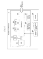
- Fig. 5 is a block diagram illustrating a configuration of a control unit 91 in the recording apparatus according to the present exemplary embodiment.
- a central processing unit (CPU) 501 controls various mechanisms in the apparatus via a controller 502 based on various programs stored in a read-only memory (ROM) 504.
- ROM read-only memory
- RAM random access memory
- Image data is transmitted from an external host apparatus which is connected to the recording apparatus, and the CPU 501 performs image processing for converting the image data into a recording signal with which the recording apparatus can perform the recording operation.
- Various motors 506 are driven by a motor driver 507, and the recording head 7 is driven by a recording head driver 509, so that an image is recorded on a recording medium.
- the motor 506 collectively represents a plurality of motors such as the conveyance motor 35 and a motor for driving the carriage 50, and the motor driver 507 collectively represents the motor drivers thereof.
- An electrically erasable programmable read-only memory (EEPROM) 508 stores setting values set in a factory or on a user site and data to be updated, and these data pieces are used by the controller 502 and the CPU 501 as control parameters.
- a sensor 505 collectively represents temperature sensors and encoder sensors disposed at various positions in the apparatus, and the above-described conveyance-roller encoder sensor 363 is also included in the sensor 505.
- the CPU 501 increments counter information in a ring buffer in the RAM 503 each time a slit is detected by the conveyance-roller encoder sensor 363.
- Calculation formulae for calculating the one remaining conveyance amount from two conveyance amounts, which are described below, are stored in the ROM 504.
- the conveyance amount, a conveyance-amount correction value, and the like which are obtained by actual measurement or calculation are stored in the EEPROM 508.
- the conveyance amount is corrected while these formulae and values are suitably referred to or calculated.
- a conveyance amount when the conveyance roller 36 and the discharge roller 40 cooperatively convey the recording medium is calculated on the assumption that the respective conveyance amounts of the conveyance roller 36 and the discharge roller 40 are known when the conveyance roller 36 and the discharge roller 40 are respectively rotated by the same predetermined rotation amount. More specifically, the case of calculating the conveyance amount in the second conveyance state from the respective conveyance amounts in the first and third conveyance states will be described.
- a conveyance amount (conveyance distance) with respect to a predetermined rotation amount (predetermined rotation angle) of the conveyance roller (i.e. LF roller) is defined as ⁇ LF
- a conveyance amount (conveyance distance) with respect to a predetermined rotation amount predetermined rotation angle) of the discharge roller (i.e., EJ roller) is defined as ⁇ EJ.
- These two conveyance amounts ⁇ LF and ⁇ EJ are respectively actually measured and calculated in advance using techniques for actually measuring the conveyance amount, which are described below.
- the conveyance amounts ⁇ LF and ⁇ EJ meet a relationship of ⁇ LF > ⁇ EJ (this situation can be easily realized if the diameter of the LF roller is made larger than that of the EJ roller).
- a conveyance amount when the conveyance roller 36 and the discharge roller 40 cooperatively convey the recording medium is defined as the conveyance amount ⁇ LFEJ.
- the conveyance amount ⁇ LFEJ is calculated from the known conveyance amounts ⁇ LF and ⁇ EJ.
- the conveyance amount of the recording medium conveyed by both the conveyance roller 36 and the discharge roller 40 is between the two conveyance amounts.
- the conveyance roller 36 conveying a sheet for a greater amount with respect to the predetermined rotation amount causes a force (forward tension) pressing an outer circumferential surface of the discharge roller 40 conveying the sheet for a less amount in the downstream direction of the conveyance direction via the recording medium to act on the outer circumferential surface of the discharge roller 40.
- a force for assisting the recording medium in conveyance is applied to the discharge roller 40 from the conveyance roller 36 by the force (forward tension).
- the conveyance distance of the recording medium per the predetermined rotation angle (for example, a unit rotation angle) of the discharge roller 40 is apparently increased.
- a force equal to the force applied to the discharge roller 40 occurs in an opposite direction (an upstream direction with respect to the conveyance direction) on an outer circumferential surface of the conveyance roller 36 from the law of action and reaction (back tension).
- the conveyance distance of the recording medium per the predetermined rotation angle of the conveyance roller 36 (for example, the unit rotation angle) is apparently decreased by the back tension.
- the forces are applied and received between the rollers via the recording medium so that the conveyance amounts of both the rollers per the unit rotation angle are apparently equal to each other. Consequently, the conveyance amount ⁇ LFEJ is between the conveyance amounts ⁇ LF and ⁇ EJ. Because the force is made to interact between the rollers, the conveyance amount ⁇ LFEJ is influenced by a conveyance characteristic to an external force (load) of each roller.
- the conveyance characteristic to the load will be described.
- the conveyance amount of the recording medium it is known that if a load is generated via the recording medium, the recording medium slips to decrease a feed amount. How much slip is generated to a load of a weight can be easily obtained in an experiment by actually measuring the conveyance amount of the recording medium when hanging a weight having a known weight and rotating the roller by the predetermined rotation angle while applying the load to the recording medium. For example, a graph illustrated in Fig. 9 can be obtained in the experiment.
- the conveyance characteristic coefficient ⁇ is a value indicating a slip amount to the load.
- the conveyance characteristic coefficient ⁇ is calculated according to ⁇ (conveyance amount when load is applied) - (conveyance amount when load is not applied) ⁇ /(magnitude of load). Consequently, the conveyance characteristic coefficient ⁇ is expressed in the unit of (mm/N), and has a negative value.
- the conveyance characteristic coefficient ⁇ can be obtained in the experiment for the conveyance roller 36 and the discharge roller 40, respectively. The values are defined as ⁇ LF and ⁇ EJ.
- the conveyance amount ⁇ LFEJ in the two shafts is the conveyance amount when the load is applied to each roller
- the conveyance amount ⁇ LFEJ can be expressed by the formula using the conveyance characteristic coefficient ⁇ for each roller. Consequently, when, for the force made to interact between the rollers, a load applied to the conveyance roller 36 is defined as FLF, and a load applied to the discharge roller 40 is defined as FEJ, the conveyance amount ⁇ LFEJ can be described in the forms of a formula 1 and a formula 2 for each roller.
- FLF -FEJ is set from the law of action and reaction.
- the conveyance amount ⁇ LFEJ can be expressed by the form of a formula 3 using the conveyance amounts ⁇ LF and ⁇ EJ, and the conveyance characteristic coefficients ⁇ LF and ⁇ EJ.
- ⁇ LFEJ 1 / ⁇ LF / 1 / ⁇ LF + 1 / ⁇ EJ ⁇ ⁇ LF + 1 / ⁇ LF / 1 / ⁇ LF + 1 / ⁇ EJ ⁇ ⁇ EJ
- the conveyance amount ⁇ LFEJ is obtained by subjecting the conveyance amounts ⁇ LF and ⁇ EJ to weighted average using 1/ ⁇ LF and 1/ ⁇ EJ.
- ⁇ LFEJ ⁇ LF / ⁇ LF + ⁇ EJ ⁇ ⁇ LF + ⁇ EJ / ⁇ LF + ⁇ EJ ⁇ ⁇ EJ
- the conveyance-amount correction value is calculated in the factory or the user's site before actual printing is performed.
- a recording medium is conveyed in a state where the rotation amount of the roller is managed.
- the conveyance amount of the recording medium in any two conveyance states among the three conveyance states is actually measured.
- the conveyance amount for the predetermined rotation amount is converted from the actually measured result.
- a conveyance amount in the one remaining conveyance state is calculated from the conveyance amounts in the obtained two conveyance states using the formula 3 or the formula 4.
- conveyance-amount correction values in the three conveyance states are calculated based on the three conveyance amounts.
- the conveyance amount in only the conveyance roller 36 which is in the first conveyance state is actually measured, and the conveyance amount in only the discharge roller 40 which is in the third conveyance state are actually measured will be described.
- a conveyance amount in the two shafts, namely the conveyance roller 36 and the discharge roller 40 which are in the second conveyance state is calculated by these two actually measured results.
- Fig. 10 is a table which stores conveyance-amount correction values and values required for calculating these conveyance-amount correction values in the respective conveyance states according to the first exemplary embodiment.
- conveyance amounts TLF, TLFEJ, and TEJ indicate conveyance amounts for the predetermined rotation amount.
- the conveyance amounts TLF, TLFEJ, and TEJ are stored as the conveyance amount for one rotation of the roller.
- the conveyance characteristic coefficients ⁇ LF and ⁇ EJ indicate the slip amount to the load, and are stored in advance.
- Conveyance-amount correction values SLF, SLFEJ, and SEJ are stored correction values, which are described below.
- Fig. 6 illustrates an example of test patterns for acquiring the conveyance amounts TLF and TEJ related to the first and third conveyance states among the three conveyance amounts.
- test pattern is recorded in the conveyance of only the conveyance roller 36 which is in the first conveyance state. After the sheet passes through the conveyance roller 36, and is conveyed to a test pattern recording position, a first test pattern 0701 is recorded. After the pattern recording is ended, the roller is slightly rotated in a state where the roller rotation amount is managed, and a second test pattern 0702 is recorded. Similarly, the roller is slightly rotated, and a third test pattern 0703 is recorded.
- the sheet is conveyed to a position corresponding to one rotation of the roller from the recording position of the first test pattern 0701, and a fourth test pattern 0711 is recorded. Then, while the roller is rotated as needed to convey the sheet, fifth and sixth test patterns 0712 and 0713 are recorded at positions corresponding to one rotation of the roller from the recording positions of the second and third test patterns 0702 and 0703. Due to the above-described operation, the test pattern recording in the first conveyance state is completed.
- An interval between the first test pattern 0701 and the fourth test pattern 0711 corresponds to the conveyance amount for one rotation of the conveyance roller 36.
- an interval between the second and fifth test patterns 0702 and 0712 and an interval between the third and sixth test patterns 0703 and 0713 also correspond to the conveyance amount for one rotation of the conveyance roller 36.
- the test pattern recording is performed in the conveyance of only the discharge roller 40 which is in the third conveyance state.
- a first test pattern 0721 is recorded.
- five test patterns 0722 to 0733 are recorded while the roller rotation amount is controlled by the similar method as that of the test pattern recording in the first conveyance state described above. Accordingly, intervals between the test patterns 0721 and 0731, the test patterns 0722 and 0732, and the test patterns 0723 and 0733 correspond to the conveyance amount for one rotation of the discharge roller 40.
- the sheet on which the patterns are recorded is fed again.
- the intervals between the test patterns 0701 and 0711, the test patterns 0702 and 0712, and the test patterns 0703 and 0713 are measured by an optical sensor 511 (illustrated in Fig. 4 ) installed in the carriage 50.
- the intervals between the test patterns 0721 and 0731, the test patterns 0722 and 0732, and the test patterns 0723 and 0733 are measured by the similar measuring method.
- the conveyance amounts for one rotation of the conveyance roller 36 and the discharge roller 40 can be acquired by measuring these intervals.
- An average value of the three intervals measured in the region of each of the first and third conveyance states is stored in the respective conveyance amounts TLF and TEJ in the first and third conveyance states.
- the three measured intervals are averaged, and stored as the conveyance amount T to reduce an error such as stop variation of the roller assumed during the test pattern recording, or measurement variation assumed during measurement.
- the conveyance amount is periodically varied according to the rotation phase of the roller by the eccentricity of the roller or the like. Because the correction of a center value in a periodic variation of the unit conveyance amount (conveyance speed) of the roller is considered in the present exemplary embodiment, one period of the rotation of the roller, that is the conveyance amount for one rotation is actually measured and calculated.
- the conveyance amount TLFEJ in the second conveyance state where the conveyance amount is not actually measured is calculated and stored.
- the conveyance amount TLFEJ is calculated according to the formula 3 using the previously stored conveyance characteristic coefficients ⁇ LF and ⁇ EJ, or the stored conveyance amounts TLF and TEJ. Because the conveyance amounts TLF and TEJ express the conveyance amount per the predetermined rotation amount, the conveyance amount can be calculated by respectively substituting the conveyance amounts TLF and TEJ for the conveyance amounts ⁇ LF and ⁇ EJ of the formula 3. The conveyance amount thus calculated is stored in TLFEJ. Consequently, the conveyance amounts T in the three conveyance states can be obtained.
- a conveyance-amount correction value S is stored for each of the conveyance states. More specifically, values obtained by subtracting the measured actual conveyance amounts TLF, TLFEJ, and TEJ of the respective conveyance states from ideal conveyance amounts ITLF, ITLFEJ, and ITEJ for one rotation of the roller at the time of image recording are stored as correction values SLF, SLFEJ, and SEJ.
- SLF ITLF - TLF
- SLFEJ ITLFEJ - TLFEJ
- SEJ ITEJ - TEJ
- the conveyance-amount correction values S in all the three conveyance states can be obtained from the actual measurement of the conveyance amounts in the two conveyance states. Because a conveyance deviation corresponding to the conveyance-amount correction value occurs when the recording medium is actually conveyed for one rotation of the roller, the recording medium can be conveyed by the ideal conveyance amount by adding the rotation amount corresponding to the conveyance-amount correction value.
- the conveyance amounts in the first and third conveyance states are actually measured.
- the conveyance amounts in the second and third conveyance states can be actually measured, and the conveyance amount ⁇ LF can be calculated and obtained based on the stored conveyance amounts ⁇ LFEJ and ⁇ EJ.
- the conveyance amount in the one remaining conveyance state can be calculated according to the formula 3 by actually measuring the conveyance amounts in any two conveyance states among the three conveyance states.
- the test pattern is not limited to the pattern illustrated in Fig. 6 .
- the two conveyance states may be arbitrarily selected, and the conveyance amounts may be actually measured by patterns corresponding to the selected conveyance states.
- the intervals between the test patterns for example, one rotation of the roller may be divided, and the conveyance amount may be actually measured by the sum of the intervals.
- the predetermined rotation amount which defines the conveyance amount T is different from the rotation amount of the interval between the test patterns, it is necessary to convert the actually measured result into the predetermined rotation amount, and to store the actually measured result.
- Fig. 7 illustrates a control flowchart for conveyance amount correction in each conveyance state during the actual recording operation.
- a sheet is fed from the sheet feeding unit 21, and the sheet enters the edge sensor 321 located on the upstream side of the conveyance roller 36.
- the position of the leading edge of the sheet is detected by the edge sensor 321 to calculate a roller rotation amount to an actual record starting position.
- the sheet is conveyed based on the calculated roller rotation amount, and the sheet is positioned to the record starting position. In this case, because the leading edge of the sheet passes through the conveyance roller 36, the conveyance of the sheet proceeds to the first conveyance state.
- step S0803 the recording operation is performed on the leading edge region of the sheet.
- the recording operation is executed by repeating the movement of the recording head 7 by the carriage 50 and the conveyance by the conveyance roller 36.
- the conveyance-amount correction value SLF is applied in the conveyance of the conveyance roller 36 to adjust the roller rotation amount, and accordingly the conveyance amount correction in the first conveyance state is executed.
- the conveyance-amount correction value SLF is the correction value indicating the conveyance deviation from the ideal conveyance amount for one rotation of the roller
- the conveyance amount correction is performed by adding the rotation amount corresponding to the conveyance deviation amount using the conveyance-amount correction value SLF to the actual roller rotation amount.
- the ideal conveyance amount for one rotation of the roller is defined as L
- the actual roller rotation amount is defined as ⁇
- the rotation amount is calculated by ⁇ (SLF/L) ⁇ . Consequently, the conveyance of the ideal conveyance amount for the rotation amount q of the roller can be realized by driving the roller by the rotation amount ⁇ (1+SLF/L) ⁇ corrected by adding the rotation amount.
- the actual conveyance amount can be brought close to the ideal conveyance amount by correcting the rotation amount (driving amount).
- the rotation amount is managed by counting the number of slits on the code wheel 362 by the conveyance-roller encoder sensor 363.
- the above-described conveyance amount correction by the correction value SLF is continuously performed until the conveyance just before the leading edge of the sheet enters the discharge roller 40.
- step S0804 then, the leading edge of the sheet enters the discharge roller 40, and the state proceeds to the second conveyance state.
- step S0805 the conveyance-amount correction value applied up to here is switched to the conveyance-amount correction value SLFEJ.
- the recording operation of the intermediate region of the sheet is executed while the roller rotation amount is adjusted by the correction value SLFEJ.
- the conveyance amount correction to which the correction value SLFEJ is applied is performed in the similar manner to the correction method by the conversion of the correction value SLF described in step S0803.
- the conveyance amount correction by the correction value SLFEJ is continuously performed until the conveyance just before the trailing edge of the sheet passes through the conveyance roller 36.
- the timing at which the trailing edge of the sheet passes through the conveyance roller 36 may be calculated based on a detection position of the leading edge of the sheet and a sheet length input by recorded image information.
- the timing may be also calculated by newly detecting a position of the trailing edge of the sheet by the edge sensor 321.
- step S0807 the conveyance-amount correction value applied is switched to the correction value SEJ. Then, the recording operation of the trailing edge region of the sheet is executed while the conveyance amount is corrected by the correction value SEJ in the similar manner to the above-described correction method. After the recording operation is ended, the image recording of the entire region of the sheet is completed. Then, the sheet on which the image is recorded is discharged on a discharge tray by the discharge roller 40, and the image recording operation is completed.
- the conveyance amount correction in all the three conveyance states can be performed only by actually measuring the conveyance amounts of the two conveyance states among the three conveyance states having different conveyance amounts during the recording operation to the recording medium. Therefore, a measurement time can be shortened without impairing conveyance accuracy as compared with the case where all the three conveyance states are actually measured. As this effect, manufacturing cost reduction can be expected by shortening a tact time when the conveyance amount is actually measured in the factory or the like, for example.
- the conveyance-amount correction value can be acquired without stress by time shortening.
- the rotational speed ratio between the conveyance roller 36 and the transmission gear is 1:1 in the configuration according to the present exemplary embodiment.
- the rotational speed ratio between the conveyance roller 36 and the transmission gear is not limited to 1:1.
- the rotational speed ratio between one rotation of the conveyance roller 36 and the idler gear 45 or the discharge roller 40 may be an integral multiple or a fraction of an integer.
- the conveyance amount for one rotation of the conveyance roller 36 may be actually measured regardless of the rotational speed ratio in the first conveyance state (m and n are integers). However, in the second conveyance state, it is necessary to actually measure the conveyance amount for m ⁇ n rotations of the conveyance roller 36. The actually measured conveyance amount is converted into the predetermined rotation amount, and is stored in the conveyance amount T, so that the conveyance-amount correction value S can be obtained.
- the conveyance amount can be presumed from the magnitude of the load using the conveyance characteristic coefficient ⁇ which indicates the slip amount to the load. Accordingly, if the load is applied to the sheet, the conveyance amount T can be obtained, and the conveyance amount correction in each conveyance state can be executed.
- the calculation of the conveyance amount in a different conveyance state using the conveyance amount based on the actually measured result is described.
- the value to be used for the calculation is not limited to the conveyance amount.
- the conveyance-amount correction value is previously obtained by actual measurement, and a conveyance-amount correction value in the different conveyance state can also be obtained using the previously obtained conveyance-amount correction value.
- the concept of the correction value may be added to the calculation formula described in the present exemplary embodiment to convert the calculation formula.
- ITLFEJ - SLFEJ ⁇ LF / ⁇ LF + ⁇ EJ ⁇ ITLF - SLF + ⁇ EJ / ⁇ LF + ⁇ EJ ⁇ ITEJ - SEJ
- the ideal conveyance amounts ITLF and ITEJ can be obtained from the diameter of the roller and the rotation angle of the roller.
- the ideal conveyance amounts ITLF, ITEJ, and ITLFEJ meet the relationship of a formula 12.
- ITLFEJ ⁇ LF / ⁇ LF + ⁇ EJ ⁇ ITLF + ⁇ EJ / ⁇ LF + ⁇ EJ ⁇ ITEJ
- the remaining correction value can be calculated using the formula 11 or 13.
- the control illustrated in Fig. 7 is performed using the correction value thus obtained.
- the first exemplary embodiment calculates the conveyance amount in the one remaining conveyance state from the actual measurement of the conveyance amounts in the two conveyance states when the two rollers are used to convey a recording medium, and performs the conveyance amount correction in each conveyance state.
- the concept of calculating the conveyance amount described in the first exemplary embodiment can be applied in not only the case where two rollers are used but also the case where a plurality of rollers are used. Consequently, in a second exemplary embodiment, the case where three rollers are used to convey a recording medium and a conveyance amount in each conveyance state is obtained by actual measurement or calculation will be described.
- Fig. 8 is a schematic sectional view particularly illustrating a conveyance mechanism including a sheet conveyance unit in a recording apparatus according to the second exemplary embodiment.
- a recording medium is conveyed using three rollers, i.e., an upstream roller 60, an intermediate roller 70, and a downstream roller 80.
- a fed recording medium is guided by a guide member (not illustrated), and enters an upstream roller pair including the upstream roller 60 and a pinch roller 62 and is conveyed.
- the recording medium conveyed by the upstream roller pair enters an intermediate roller pair including the intermediate roller 70 and an intermediate spur 72 and is further conveyed.
- the recording medium enters a downstream roller including the downstream roller 80 and a downstream spur 82.
- image recording is suitably performed by recording heads 67 and 68, and an image is recorded on the recording medium.
- the recording medium is finally discharged to a discharge tray (not illustrated) by the downstream roller 80.
- a recording medium is conveyed while a conveyance state is changed.
- a conveyance state of the recording medium a conveyance state where the recording medium is conveyed only by the upstream roller 60 is defined as a conveyance state CA; a conveyance state where the recording medium is conveyed only by the intermediate roller 70 is defined as a conveyance state CB; and a conveyance state where the recording medium is conveyed only by the downstream roller 80 is defined as a conveyance state CC.
- a conveyance state where the recording medium is conveyed by the two shafts i.e., the upstream roller 60 and the intermediate roller 70 is defined as a conveyance state CAB.
- a conveyance state where the recording medium is conveyed by the two shafts, i.e., the intermediate roller 70 and the downstream roller 80 is defined as a conveyance state CBC. Furthermore, for a conveyance state in three shafts, a conveyance state where the recording medium is conveyed by the three shafts, i.e., the upstream roller 60, the intermediate roller 70, and the downstream roller 80 is defined as a conveyance state CABC. Depending on a length of the recording medium in the conveyance direction, the conveyance according to the present exemplary embodiment is executed by a maximum of the six conveyance states.
- Fig. 11 illustrates a table which stores conveyance-amount correction values and values required for calculating these correction values in the respective conveyance states according to the present exemplary embodiment.
- a conveyance amount T for a predetermined rotation amount, a conveyance characteristic coefficient ⁇ , and a conveyance-amount correction value S are provided for each conveyance state.
- the conveyance characteristic coefficient ⁇ is a value which indicates a slip amount to a load for each individual roller as described above
- the conveyance characteristic coefficient ⁇ is set only in the conveyance states CA, CB, and CC which are conveyance states due to only one roller.
- the conveyance amount T in the remaining conveyance state is calculated from the conveyance amounts T which are stored based on the actually measured results of the plurality of conveyance states, and the conveyance-amount correction value S in each conveyance state is obtained.
- roller rotation control for the conveyance amount correction is performed using the conveyance-amount correction value S according to the conveyance state.
- a method for calculating a conveyance amount in each conveyance state will be described.
- a basic concept of calculation of the conveyance amount is similar to that described above. More specifically, the concept is based on the relationship "the cooperative conveyance amount of a plurality of conveyance units is a conveyance amount obtained by subjecting the conveyance amount of each conveyance unit to weighted average with difficulty of slipping of each conveyance unit to a load as a weighting coefficient".
- the first exemplary embodiment describes the case where the two rollers are related to the conveyance. However, the concept can be applied even when not only the two rollers but also more rollers are related to the conveyance.
- TAB 1 / ⁇ A / 1 / ⁇ A + 1 / ⁇ B ⁇ TA + 1 / ⁇ B / 1 / ⁇ A + 1 / ⁇ B ⁇ TB
- TBC 1 / ⁇ B / 1 / ⁇ B + 1 / ⁇ C ⁇ TB + ( 1 / ⁇ C / ( 1 / ⁇ B + 1 / ⁇ C ) ) ⁇ TC
- the conveyance amount in the conveyance state to which the three rollers are related i.e., the conveyance amount TABC in the conveyance state CABC can be described in the form of the following formula 14 based on the same concept. More specifically, the conveyance amount TABC is expressed by subjecting conveyance amounts TA, TB, and TC to weighted average according to conveyance strengths 1/ ⁇ A, 1/ ⁇ B, and 1/ ⁇ C.
- TABC 1 / ⁇ A ⁇ TA + 1 / ⁇ B ⁇ TB + 1 / ⁇ C ⁇ TC / 1 / ⁇ A + 1 / ⁇ B + 1 / ⁇ C
- the conveyance amounts in all the conveyance states related to the image recording can be calculated by actually measuring the conveyance amounts in the suitable number of the conveyance states according to the formulae 14, 15, and 16.
- the conveyance characteristic coefficients ⁇ A, ⁇ B, and ⁇ C are stored in advance as in the first exemplary embodiment. Therefore, if the conveyance amounts TA, TB, and TC are obtained by actual measurement, all the right sides of the three calculation formulae: the formulae 4 and 5; the formulae 6 and 7; and the formulae 8, 9, and 10 are known. Consequently, the conveyance amounts in all the conveyance states can be obtained. More specifically, the conveyance-amount correction values S in all the six conveyance states can be obtained by actually measuring the conveyance amounts in the three conveyance states, and the conveyance amount correction in all the conveyance states can be performed.
- the conveyance state CB where the sheet is conveyed only by the intermediate roller 70 does not exist.
- the conveyance amounts in all the conveyance states can be obtained from the actual measurement of the conveyance amounts in the three conveyance states of the following combinations. For example, if the conveyance amounts TA and TC as well as the conveyance amount TAB are obtained by the actual measurement, the conveyance amount TB can be calculated according to the formula 14. Then, if the formulae 15 and 16 are solved using the calculated conveyance amount TB, the conveyance amounts in all the conveyance states can be obtained.
- the conveyance amounts TA, TAB, and TABC are obtained by the actual measurement, all the conveyance amounts can be obtained by the similar method. Therefore, when the three rollers are used to convey the recording medium, the conveyance amounts in all the remaining conveyance states can be obtained from the actual measurement of the conveyance amounts in the appropriately selected three conveyance states.
- the present exemplary embodiment describes the case where the three rollers are used.
- the conveyance amounts in all the conveyance states can be obtained by actually measuring the conveyance amounts in the conveyance states of the number of the used rollers.
- the conveyance states of the maximum number of ⁇ n ⁇ (n+1)/2 ⁇ exist.
- the "n" conveyance states may be actually measured. This is because the calculation formula of the conveyance amount in the conveyance state where the other plurality of rollers cooperatively convey the recording medium can be written by the conveyance amount and the conveyance characteristic coefficient in each roller, and if the conveyance amount in each roller is obtained, all the conveyance amounts can be obtained. Further, if the conveyance amount in an arbitrary roller is not actually measured, conversion can be performed by the conveyance amount in the conveyance state to which the roller is related.
- the value to be used for calculation is not limited to the conveyance amount, and calculation may be performed based on the conveyance-amount correction value. More specifically, the effect of the present embodiment can be exhibited without being limited to the calculation process based on the relationship "the cooperative conveyance amount of a plurality of conveyance units is a conveyance amount obtained by subjecting the conveyance amount of each conveyance unit to weighted average with difficulty of slipping of each conveyance unit to a load as a weighting coefficient".
- the conveyance roller 36 When a recording medium is conveyed only by the conveyance roller 36, the conveyance roller 36 is designed so that the recording medium is conveyed by a predetermined distance ILLF by rotating the conveyance roller 36 by ⁇ LF. More specifically, the radius of the conveyance roller 36 is determined.
- the conveyance roller 36 is rotated by ⁇ LF, the rotational speed ratio in design between the conveyance roller 36 and the discharge roller 40 is set so that the discharge roller 40 is rotated by ⁇ EJ.
- the discharge roller 40 is designed so that the recording medium is conveyed by the conveyance amount ILLF by rotating the discharge roller 40 by ⁇ EJ when the recording medium is conveyed only by the discharge roller 40.
- the recording medium is conveyed by the conveyance amount ILLFEJ in the case where the conveyance roller 36 is rotated by ⁇ LF and the discharge roller 40 is rotated by ⁇ EJ.
- the actual measured value of the conveyance amount in the case where the conveyance roller 36 is rotated by ⁇ LF when the recording medium is conveyed only by the conveyance roller 36 is defined as TLLF.
- the actual measured value of the conveyance amount in the case where the discharge roller 40 is rotated by ⁇ EJ when the recording medium is conveyed only by the discharge roller 40 is defined as TLEJ.
- the actual measured value of the conveyance amount in the case where the conveyance roller 36 is rotated by ⁇ LF and the discharge roller 40 is rotated by ⁇ EJ when the recording medium is conveyed by the conveyance roller 36 and the discharge roller 40 is defined as TLLFEJ.
- a difference between the actual measured value of the conveyance amount and the ideal conveyance amount is a correction value.
- ITLLFEJ ⁇ LF / ⁇ LF + ⁇ EJ ⁇ ITFL + ⁇ EJ / ⁇ LF + ⁇ EJ ⁇ ITLEJ
- the correction value when the recording medium is conveyed by both the conveyance roller 36 and the discharge roller 40 can be calculated by subjecting the correction value when the recording medium is conveyed by each individual roller to weighted average using the conveyance strength of each roller as weight.
- the remaining correction value can be calculated using the formula 11 or 13.
- the conveyance roller 36 When the recording medium is conveyed by the conveyance amount ILLF only by the conveyance roller 36, the conveyance roller 36 is driven by ⁇ (1 + SLLF/ILLF) ⁇ LF ⁇ .
- the discharge roller 40 When the recording medium is conveyed by the conveyance amount ILEJ only by the discharge roller 40, the discharge roller 40 is driven by ⁇ (1 + SLEJ/ILEJ) ⁇ EJ ⁇ .
- the conveyance roller 36 and the discharge roller 40 are respectively rotated by ⁇ (1 + SLLFEJ/ILLFEJ) ⁇ LF ⁇ and ⁇ (1 + SLLFEJ/ILLFEJ) ⁇ EJ ⁇ .
- the rotation angle of the roller of the required conveyance amount may be obtained based on these values, and may be corrected.
- a conveyance amount in an unknown conveyance state can be calculated from the conveyance amount in the known conveyance state. Because the calculation formula used to calculate the conveyance amount is based on the relational formula of the conveyance amount of each conveyance unit, the correction accuracy of the conveyance amount is not decreased. Therefore, the above-described exemplary embodiments can shorten a measurement time without impairing the correction accuracy compared with the conventional technique which actually measures and corrects the conveyance amounts in all the conveyance states.
Landscapes
- Handling Of Sheets (AREA)
- Controlling Sheets Or Webs (AREA)
Applications Claiming Priority (1)
| Application Number | Priority Date | Filing Date | Title |
|---|---|---|---|
| JP2012203097A JP6061579B2 (ja) | 2012-09-14 | 2012-09-14 | 記録装置および搬送量の補正値の算出方法 |
Publications (2)
| Publication Number | Publication Date |
|---|---|
| EP2708366A2 true EP2708366A2 (de) | 2014-03-19 |
| EP2708366A3 EP2708366A3 (de) | 2018-03-14 |
Family
ID=49236981
Family Applications (1)
| Application Number | Title | Priority Date | Filing Date |
|---|---|---|---|
| EP13004447.2A Withdrawn EP2708366A3 (de) | 2012-09-14 | 2013-09-12 | Förderungsvorrichtung und Verfahren zur Berechnung des Förderungskorrekturwertes |
Country Status (4)
| Country | Link |
|---|---|
| US (1) | US8926054B2 (de) |
| EP (1) | EP2708366A3 (de) |
| JP (1) | JP6061579B2 (de) |
| CN (1) | CN103660623B (de) |
Families Citing this family (5)
| Publication number | Priority date | Publication date | Assignee | Title |
|---|---|---|---|---|
| US9162498B2 (en) * | 2013-12-24 | 2015-10-20 | Canon Kabushiki Kaisha | Ink jet printing apparatus and image processing apparatus |
| JP6123725B2 (ja) * | 2014-03-31 | 2017-05-10 | ブラザー工業株式会社 | 記録装置 |
| JP2015202655A (ja) * | 2014-04-15 | 2015-11-16 | キヤノン株式会社 | 画像形成装置、その制御方法とプログラム |
| US9168737B1 (en) | 2015-01-29 | 2015-10-27 | Funai Electric Co., Ltd. | System and method for ejecting adjustable amounts of ink |
| US12050478B2 (en) * | 2019-07-25 | 2024-07-30 | Siemens Aktiengesellschaft | Conveyor assembly with two conveyor elements connected in parallel |
Citations (1)
| Publication number | Priority date | Publication date | Assignee | Title |
|---|---|---|---|---|
| JP2008030455A (ja) | 2006-07-03 | 2008-02-14 | Seiko Epson Corp | 記録方法 |
Family Cites Families (20)
| Publication number | Priority date | Publication date | Assignee | Title |
|---|---|---|---|---|
| JPH1149399A (ja) * | 1997-07-29 | 1999-02-23 | Brother Ind Ltd | シート搬送装置およびシート搬送装置におけるシート搬送量の補正方法 |
| JP3885418B2 (ja) * | 1999-04-19 | 2007-02-21 | 富士ゼロックス株式会社 | 印刷装置 |
| JP2003320718A (ja) * | 2002-05-08 | 2003-11-11 | Seiko Epson Corp | 記録装置および紙送り補正方法 |
| JP5067017B2 (ja) * | 2006-06-20 | 2012-11-07 | セイコーエプソン株式会社 | システム、プリンター、及びプリンターにおいて実行される方法。 |
| US7992992B2 (en) * | 2006-08-25 | 2011-08-09 | Seiko Epson Corporation | Transport amount correcting method, recording apparatus, and storage medium having program stored thereon |
| JP4240102B2 (ja) * | 2006-09-29 | 2009-03-18 | ブラザー工業株式会社 | シート搬送装置、及びシート搬送方法 |
| JP2008105345A (ja) * | 2006-10-27 | 2008-05-08 | Seiko Epson Corp | 記録装置、記録方法、及び、プログラム |
| JP2009056636A (ja) * | 2007-08-30 | 2009-03-19 | Brother Ind Ltd | 画像記録装置 |
| JP2009083130A (ja) * | 2007-09-27 | 2009-04-23 | Seiko Epson Corp | 液体吐出装置、及び、搬送方法 |
| JP5371322B2 (ja) * | 2008-08-25 | 2013-12-18 | キヤノン株式会社 | 記録装置および搬送制御方法 |
| US8235309B2 (en) * | 2008-08-25 | 2012-08-07 | The United States Of America As Represented By The Administrator Of The National Aeronautics And Space Administration | Advanced high performance horizontal piezoelectric hybrid synthetic jet actuator |
| JP2010215345A (ja) * | 2009-03-16 | 2010-09-30 | Ricoh Co Ltd | 用紙搬送装置及び画像形成装置 |
| JP2010214762A (ja) * | 2009-03-17 | 2010-09-30 | Alps Electric Co Ltd | プリンタおよび記録用紙の搬送量調整方法 |
| JP5239992B2 (ja) * | 2009-03-25 | 2013-07-17 | セイコーエプソン株式会社 | 記録装置における搬送誤差補正方法 |
| JP2010284890A (ja) * | 2009-06-11 | 2010-12-24 | Sharp Corp | 画像形成装置の用紙搬送装置 |
| JP5609201B2 (ja) * | 2010-03-25 | 2014-10-22 | セイコーエプソン株式会社 | シリアルプリンター |
| JP5246211B2 (ja) * | 2010-06-17 | 2013-07-24 | ブラザー工業株式会社 | 画像記録装置及び画像記録方法 |
| JP5803093B2 (ja) * | 2010-12-02 | 2015-11-04 | セイコーエプソン株式会社 | 印刷装置およびその制御方法 |
| JP5488455B2 (ja) * | 2010-12-28 | 2014-05-14 | ブラザー工業株式会社 | 搬送装置 |
| JP2012152948A (ja) * | 2011-01-24 | 2012-08-16 | Seiko Epson Corp | 補正値の決定方法、流体噴射装置の製造方法、及び、テストシート |
-
2012
- 2012-09-14 JP JP2012203097A patent/JP6061579B2/ja active Active
-
2013
- 2013-09-09 US US14/021,816 patent/US8926054B2/en active Active
- 2013-09-12 EP EP13004447.2A patent/EP2708366A3/de not_active Withdrawn
- 2013-09-16 CN CN201310421331.8A patent/CN103660623B/zh active Active
Patent Citations (1)
| Publication number | Priority date | Publication date | Assignee | Title |
|---|---|---|---|---|
| JP2008030455A (ja) | 2006-07-03 | 2008-02-14 | Seiko Epson Corp | 記録方法 |
Also Published As
| Publication number | Publication date |
|---|---|
| JP6061579B2 (ja) | 2017-01-18 |
| CN103660623A (zh) | 2014-03-26 |
| US8926054B2 (en) | 2015-01-06 |
| JP2014058061A (ja) | 2014-04-03 |
| US20140078211A1 (en) | 2014-03-20 |
| CN103660623B (zh) | 2016-01-06 |
| EP2708366A3 (de) | 2018-03-14 |
Similar Documents
| Publication | Publication Date | Title |
|---|---|---|
| EP2708367B1 (de) | Förderungsvorrichtung und Aufzeichnungsvorrichtung | |
| US8926054B2 (en) | Conveyance apparatus and method for calculating conveyance correction value | |
| US8286960B2 (en) | Recording apparatus and recording method | |
| EP0988986A2 (de) | Papiertransportsteuerverfahren | |
| US9375955B2 (en) | Printing apparatus and control method | |
| US8967891B2 (en) | Methods and devices for transporting a medium in a printing apparatus | |
| JP5928098B2 (ja) | 電気的装置及び設定方法 | |
| US9327527B2 (en) | Printing apparatus, conveying apparatus, and control method | |
| JP5239992B2 (ja) | 記録装置における搬送誤差補正方法 | |
| US9403653B2 (en) | Conveying apparatus, printing apparatus, control method, and sheet feeding method | |
| JP5838698B2 (ja) | 計測装置及び電気的装置 | |
| US9227809B2 (en) | Conveyance apparatus and recording apparatus | |
| US8925911B2 (en) | Sheet feeding device and image forming system | |
| US7640856B2 (en) | Method for controlling the feeding of a web substrate into a printing press | |
| CN113386475A (zh) | 一种走纸精度校准方法及校准系统 | |
| US10421634B2 (en) | Medium feeding apparatus | |
| JP2007098759A (ja) | 記録装置 | |
| JP2011213451A (ja) | 回転制御装置 | |
| JP2008273090A (ja) | インクジェットプリンタ及びインクジェットプリンタの制御方法 |
Legal Events
| Date | Code | Title | Description |
|---|---|---|---|
| PUAI | Public reference made under article 153(3) epc to a published international application that has entered the european phase |
Free format text: ORIGINAL CODE: 0009012 |
|
| AK | Designated contracting states |
Kind code of ref document: A2 Designated state(s): AL AT BE BG CH CY CZ DE DK EE ES FI FR GB GR HR HU IE IS IT LI LT LU LV MC MK MT NL NO PL PT RO RS SE SI SK SM TR |
|
| AX | Request for extension of the european patent |
Extension state: BA ME |
|
| PUAL | Search report despatched |
Free format text: ORIGINAL CODE: 0009013 |
|
| AK | Designated contracting states |
Kind code of ref document: A3 Designated state(s): AL AT BE BG CH CY CZ DE DK EE ES FI FR GB GR HR HU IE IS IT LI LT LU LV MC MK MT NL NO PL PT RO RS SE SI SK SM TR |
|
| AX | Request for extension of the european patent |
Extension state: BA ME |
|
| RIC1 | Information provided on ipc code assigned before grant |
Ipc: B41J 11/46 20060101AFI20180206BHEP Ipc: B41J 13/00 20060101ALI20180206BHEP |
|
| STAA | Information on the status of an ep patent application or granted ep patent |
Free format text: STATUS: THE APPLICATION HAS BEEN WITHDRAWN |
|
| 18W | Application withdrawn |
Effective date: 20180612 |