EP2708397B1 - Zwangsgeführter Klappspriegel - Google Patents
Zwangsgeführter Klappspriegel Download PDFInfo
- Publication number
- EP2708397B1 EP2708397B1 EP13183737.9A EP13183737A EP2708397B1 EP 2708397 B1 EP2708397 B1 EP 2708397B1 EP 13183737 A EP13183737 A EP 13183737A EP 2708397 B1 EP2708397 B1 EP 2708397B1
- Authority
- EP
- European Patent Office
- Prior art keywords
- folding
- transport container
- stop
- load transport
- bracket
- Prior art date
- Legal status (The legal status is an assumption and is not a legal conclusion. Google has not performed a legal analysis and makes no representation as to the accuracy of the status listed.)
- Active
Links
Images



Classifications
-
- B—PERFORMING OPERATIONS; TRANSPORTING
- B60—VEHICLES IN GENERAL
- B60J—WINDOWS, WINDSCREENS, NON-FIXED ROOFS, DOORS, OR SIMILAR DEVICES FOR VEHICLES; REMOVABLE EXTERNAL PROTECTIVE COVERINGS SPECIALLY ADAPTED FOR VEHICLES
- B60J7/00—Non-fixed roofs; Roofs with movable panels, e.g. rotary sunroofs
- B60J7/02—Non-fixed roofs; Roofs with movable panels, e.g. rotary sunroofs of sliding type, e.g. comprising guide shoes
- B60J7/06—Non-fixed roofs; Roofs with movable panels, e.g. rotary sunroofs of sliding type, e.g. comprising guide shoes with non-rigid element or elements
- B60J7/061—Non-fixed roofs; Roofs with movable panels, e.g. rotary sunroofs of sliding type, e.g. comprising guide shoes with non-rigid element or elements sliding and folding
- B60J7/062—Non-fixed roofs; Roofs with movable panels, e.g. rotary sunroofs of sliding type, e.g. comprising guide shoes with non-rigid element or elements sliding and folding for utility vehicles
Definitions
- the present invention relates to a top device for a load transport container of a load transport vehicle having a limited by a tailboard and side walls of cargo space, wherein at least one of these side walls about a normally horizontal pivot axis from a closed position outwardly into an open position is pivotally comprising a roof tarpaulin and an operating device for the top tarpaulin, wherein in the intended and ready for use on the load transport container mounted state of the top device, the top tarpaulin by means of the actuator between a spread covering position and a shirred retraction position on the load transport container is movable so that it covers the loading space of the load transport container at its top in the extended covering position and in the shirred retraction position on a feed side of the load transport container in a drawer space is stored at the top releasably manner, wherein the actuator side by side slidably disposed on the load transport container and connected to the roof tarpaulin support bracket for the roof tarpaul
- top devices for load transport containers in particular for open tipping bridges, are known, for example from US Pat US 7,549,695 , Here is a mechanism with support brackets for a roof tarpaulin described, with the help of a tarpaulin over a tipping bridge can be spread.
- top device for a load transport container known.
- the top device comprises, in addition to the support brackets, the roof tarpaulin, the guide elements and a drive device and a folding bracket, which is connected to a lever device, wherein the lever device has a pivot pin which is forcibly guided along a cam ramp to the folding bracket when moving in the direction of a spread Swivel cover position.
- WO 2010/053224 A1 Another prior art is the document WO 2010/053224 A1 known. It describes a top device that can spread a roof tarpaulin over a load transport container. The guide elements of this roof tarpaulin and the associated support bracket are equipped with rollers and cable feedthrough sections. To the top device also includes a folding bracket, which has a rotary lever device, which runs in the direction of a spread covering position to a stop, so that the folding bracket is forced into a rotational movement.
- the folding bracket can be folded up elastically, which is advantageous for example in a movement of the rear side wall with an upward component, because the folding bracket can dodge soft upwards.
- a disadvantage of this construction is that the folded-down folding bracket with the roof tarp tends to swing or flutter, especially when driving over bumps or by suction and vortex shedding at higher speeds, causing noise and Cover tarpaulin and folding bracket can wear prematurely.
- the Indian DE 10 2010 003 932 A1 described propagation mechanism for the roof tarpaulin and the arrangement of the folding bracket on a guide element and the folding axis of the folding bracket can be adopted for the present invention.
- Object of the present invention is to provide an easily constructed and reliably functioning top device with ease of use, which can cover a transport container low noise and wear.
- the present invention is a top device of the type mentioned above, wherein the top device according to the invention is characterized in that the rigid stop means comprises a stop bar, the stop bar is guided along a stop rod guide, by means of the stop bar can be guided to a stop point, and the stop rod guide a Includes element of the control device for the canopy.
- Such a top device allows the folding bracket with the roof tarp relentlessly rests on the rear side wall, which prevents vibrations of the folding bracket and thus corresponding noise and wear.
- the effect of a stop device connected to the side wall is that during a part of the spreading process of the roof tarpaulin on the transport container, the stop is not engaged and thus the folding bracket is not operated. Only when Ineingriff impart the stop causes the stopper folding down the hinged bracket. The energy required for the movement of the hinged bar is removed from the covering movement and thus from its drive device by deflecting this energy via the stop device into the folding movement. The forced operation must be a stronger down-folding than through prevent the forced guidance specified.
- rigid means in terms of this invention is not complete rigidity, since all elements have an inevitable residual elasticity.
- Rigid means, however, that in the frictional connection via the stop means no explicitly provided spring element is present, whose rigidity is selectively lowered in order to make the power transmission path over the stop element softer. Excluded from this deliberately yielding elements or sections, for example, for impact damping or the like, such as a bearing sleeve made of plastic, which allow only a negligibly small elastic path of the folding bracket.
- the term rigid with respect to the type of positive guidance is coupled with the rigidity of the stop device and only leads to a compliance in the context of the inevitable elasticity of the associated components. Since the stop device is connected to the side wall directly or via intermediate elements, the stop device uses the relative speed between the propagation movement of the roof tarpaulin and the side wall to generate abutment forces and to initiate the folding bracket. This process is preferably continued over the entire downward movement of the folding bracket.
- the stop device is preferably located on a side wall of the transport container.
- the rigid stop device initiates stop forces in a lever device of the folding bracket, which faces away from the top tarpaulin with respect to the folding axis of the folding bracket. Since the folding bracket moves when spreading the roof tarp in the direction of the tailboard, it is advantageous to use the relative movement between the folding bracket and the side wall via a lever to reverse the direction of rotation when running onto a stop. If a stop element forces from the relative movement initiate directly into the folding bracket, so would the folding bracket by a Lower the movement of the roof tarpaulin in the direction of the front side wall, which makes the intended complete cover of the transport container more difficult to realize. Therefore, using a lever and initiating the impact forces in them is advantageous.
- the lever device may be a portion of the folding bracket or an additionally attached and thus rotationally connected element.
- the folding axis extends through the lever device.
- the rigid stop device comprises a stop rod.
- a stop bar preferably forms an intermediate element between a stop on a side wall or one or more intermediate elements connected thereto and the lever device of the folding bracket and connects them.
- this connection and thus the stop action is not present at any extent of the spread of the canopy, but in any case during the folding down of the folding bracket.
- the advantage of the stop bar during the stop action is that no sliding along a longitudinal guide takes place, but arise between the ends of the stop bar and the associated elements joints where there is a rotational movement that can take place as quasi-point sliding. Due to the fact that such a selective rotational sliding takes place in a smaller space, the sliding surfaces can advantageously be made smaller.
- the stopper rod is permanently articulated to the lever means.
- the start of the stop between the stopper on the hull and the stopper rod takes place.
- the stop rod may be formed as a push rod.
- the start-up and the onset of the stop action leads in this case to a pressure load on the stop rod.
- the stop rod can be designed as a pull rod.
- the stopper may then comprise, for example, a catching element, such as a hook, in which a corresponding counterpart engages the lever means of the hinged bar, or in a comparable mechanism to achieve the stopping action.
- a stop device on the side wall for such a stop bar is preferably further angeodnet in the direction of the side wall on the front side as the folding axis at the onset of the stop action.
- the pull rod then transmits tensile forces from the lever device to the stop device.
- the stop bar is guided along a stop rod guide, by means of which the stop bar can be guided to a stop point. Since the stopper rod can preferably be hingedly connected at its two ends in order to compensate for transverse movements of the stopper rod during the folding movement of the folding bracket, it is possible that the stopper rod would not hit the stopper device on the ship's side wall without a stopper rod guide during spreading of the folding top.
- the stop rod guide preferably extends essentially in the direction of propagation of the convertible top tarpaulin. Particularly preferably, the stop bar is guided during the entire propagation process of the roof tarpaulin on the stop rod guide.
- the stopper rod guide comprises an element of the operating device for the convertible top tarpaulin, in particular an actuating cable.
- the operation cable can be used twice and there is no special additional stop rod guide required.
- a guide element in the stop rod a hole is preferably provided in this, through which the actuating cable extends.
- the hole is preferably provided at one end of the stop rod.
- another existing guide for example the guidance of the guide elements, can be used as a stop rod guide.
- this has a spring element which urges the folding bracket in its folded-up position.
- This spring element is required when the stop means causes a one-sided positive guidance, which is effective only in the direction of closing the folding bracket. Otherwise, the hinged bar could not be easily folded up again.
- the spring element also causes the spring forces are transmitted from the folding bracket on the stopper.
- the spring element is designed as a tension or compression spring coil spring which is provided between the guide element of the folding bracket and the folding bracket. Alternatively or additionally, also torsion springs, torsion spring or the like can be used.
- a load transport container with a top device can be a bunk with side walls, a tipping bridge, in particular for a rear tipper, especially in one embodiment as a half pipe.
- a top device is arranged with two rigid stop devices for a folding-down movement of the folding bracket on two opposite sides, in particular on the side walls, of the transport container.
- Such a symmetrical arrangement avoids the transmission of impact forces on the folding bracket.
- the forces in the anchor device are smaller, so that the overall result is a lighter construction.
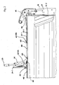
- Fig. 1 shows in a view of a generic roof device, which is not the subject of the invention, but is used to explain the hood functions.
- Fig. 1 three different positions of the folding bracket 28 are shown at the same time.
- the folding bracket 28, the lever device 36 and the pivot bearing 50 and the folding axis KA are in the Fig. 1 shown in triplicate.
- the lever device 36 is in each case rotatably mounted about the pivot bearing 50, which defines the folding axis KA, and carries at its end directed away from the transport container 10 the folding bracket 28, which on the Lever device is mounted rotationally fixed.
- the far left in the Fig. 1 shown position shows the folding bracket 28 in a folded position.
- the movement is effected by the actuator comprising the actuating cables 32-1 and 32-2, which are attached to the transport container 10 via the guide roller 81 and the guide roller holder 82.
- the Umlenkrollenhalter 82 is attached to the side board 16-2.
- the operating cable 32-1 is also attached to the clamping device 80, which transmits the movement thereof via the guide element 26 to the rotary bearing 50 and thus to the lever device 36 and the folding bracket 28.
- a non-hinged support bracket 24-1 attached to the guide element 26 also moves.
- With continued movement of the actuator in the covering position of the top of the folding bracket 28 goes from the left in Fig. 1 shown position in the middle position shown above and from this position further into a fully folded down, in Fig.
- the topping device further includes a tension spring 52 disposed between the guide member 26 and the lever device 36. This spring is extended when the folding bracket 28 is folded down. As a result, the spring 52 causes the folding bracket undergoes a bias in the direction of its folded-up position.
- the spring 52 is preferably designed as a helical spring, particularly preferably as a tension spring.
- Fig. 2 shows in a view an embodiment of the top device according to the invention in a position without stop action.
- the embodiment according to the invention comprises a stop rod 100, which is connected to the lever device 36 via a rotatable joint 103.
- a stop rod guide 101 is provided which comprises a hole, not shown. Through the hole, the operating cable 32-1 of the actuator is pulled. As a result, the stopper rod 100 is guided on the operation cable 32-1.
- the two operating cables 32-1 and 32-2 are placed around a pulley, not shown, in a Umlenkrollenhalter 82.
- the Umlenkrollenhalter 82 is attached to a fixed corner column 15.
- the guide member 26 carries a non-hinged support bracket 24-1 and the folding bracket 28.
- On the guide member 26 is also preferably a clamp for the operating cable 80 is fixed, so that the guide member 26, the non-hinged support bracket 24-1 and the folding bracket 28 with the Lever means 36 and the stopper rod 100 can be moved with the operating cable 32-1.
- the stop bar does not touch the Umlenkrollenhalter 82 at the stop 102.
- the stopper 102 is provided on the Umlenkrollenhalter 82 at a position at which a in the Fig. 2 not visible stop point 104 of the stop bar 100 abuts when the guide member 26 sufficiently far in the Fig. 2 has been moved to the right.
- the stopper rod further has a threading portion 105 which, when approaching the Umlenkrollenhalter 82 ensures that the stopper 102 on the Umlenkrollenhalter with the stop 104 of the stop rod 100 can engage by the Umlenkrollenhalter 82 at a threading of the threading 105 in the direction of Slip stop 104 slides off.
- a plurality of threading sections can be provided on the stop bar 100; in particular, in addition to the illustrated threading section 105, a second threading section (not shown) can be provided on the side of the stop bar 100 facing away from the observer at the same position in the longitudinal and transverse direction of the stop bar 100. In the position shown, the stop bar 100 is oriented substantially horizontally.
- the stop bar 100 is substantially parallel to the operating cable 32-1.
- the folding bracket 28 is in an approximately vertical plane.
- the support bracket 24-1 is located independently of the position of the folding bracket 28 with respect to the folding bracket 28 in the direction of the front side wall of the transport container 10.
- the guide element 26 is guided along a guide 110 at the upper edge of the side wall 16-2.
- Fig. 3 shows a view of the embodiment of the top device according to the invention in a position in which the stopper rod 100 is in abutment with the Umlenkrollenhalter 82.
- the guide member 26 is compared to the Fig. 2 in the Fig. 3 advanced to the right.
- the lever device 36 is articulated via the pivot 103 of the stop rod 100.
- the pivot 103 is compared to Fig. 2 moved down and in the horizontal direction to the front end of the transport container 10 out.
- the stop bar 100 is compared to its position in FIG Fig. 2 tilted.
- Fig. 4 shows a view of the embodiment of the top device according to the invention in a position in which the folding bracket 28 is completely folded down.
- the roof tarpaulin is thus completely spread over the transport container 10.
- the guide member 26 is further shifted to the right, whereby the lever means 36 is further rotated together with the folding bracket 28 in a clockwise direction. This is effected by still further articulation of the lever means 36 via the pivot 103 by means of the stop bar 100.
- the portion of the lever device 36 with the hinge 103, which in the FIGS. 2 to 4 is arranged below the pivot bearing 50 is in the position in Fig.
- FIG. 4 is shown, over a position in which the pivot 103 is substantially perpendicular below the folding axis KA, deflected out, so that the pivot 103 is disposed back up.
- the stopper rod 100 therefore has a similar inclination as in the Fig. 3 , however, has to compensate for further rotational movement at its ends on the way to this position.
- the folding bracket 28 rests on the rear side wall.
- a tension spring 52 is shown, which is stretched between the lever device 36 and a portion of the guide member 26. This spring causes the folding bracket 28 is biased toward its raised position.
Landscapes
- Engineering & Computer Science (AREA)
- Mechanical Engineering (AREA)
- Lock And Its Accessories (AREA)
Priority Applications (1)
| Application Number | Priority Date | Filing Date | Title |
|---|---|---|---|
| PL13183737T PL2708397T3 (pl) | 2012-09-12 | 2013-09-10 | Prowadzony w sposób wymuszony składany pałąk plandeki |
Applications Claiming Priority (1)
| Application Number | Priority Date | Filing Date | Title |
|---|---|---|---|
| DE102012216151.1A DE102012216151A1 (de) | 2012-09-12 | 2012-09-12 | Zwangsgeführter Klappspriegel |
Publications (2)
| Publication Number | Publication Date |
|---|---|
| EP2708397A1 EP2708397A1 (de) | 2014-03-19 |
| EP2708397B1 true EP2708397B1 (de) | 2015-11-18 |
Family
ID=49182076
Family Applications (1)
| Application Number | Title | Priority Date | Filing Date |
|---|---|---|---|
| EP13183737.9A Active EP2708397B1 (de) | 2012-09-12 | 2013-09-10 | Zwangsgeführter Klappspriegel |
Country Status (3)
| Country | Link |
|---|---|
| EP (1) | EP2708397B1 (pl) |
| DE (1) | DE102012216151A1 (pl) |
| PL (1) | PL2708397T3 (pl) |
Cited By (1)
| Publication number | Priority date | Publication date | Assignee | Title |
|---|---|---|---|---|
| US10752099B2 (en) | 2016-04-06 | 2020-08-25 | European Trailer Systems Gmbh | Tarpaulin structure |
Families Citing this family (7)
| Publication number | Priority date | Publication date | Assignee | Title |
|---|---|---|---|---|
| DE102014008952A1 (de) * | 2014-06-23 | 2015-12-24 | European Trailer Systems Gmbh | Planenaufbau |
| ITUB20152213A1 (it) * | 2015-07-15 | 2017-01-15 | Marcolin Covering S R L | Sistema di copertura |
| DE102016106322A1 (de) * | 2016-04-06 | 2017-10-12 | European Trailer Systems Gmbh | Planenaufbau |
| DE102016106321A1 (de) * | 2016-04-06 | 2017-10-12 | European Trailer Systems Gmbh | Planenaufbau |
| CN111874474B (zh) * | 2020-06-24 | 2022-07-08 | 漳州中集集装箱有限公司 | 一种篷布收展装置和篷布开顶集装箱 |
| FR3155463B1 (fr) * | 2023-11-17 | 2025-11-07 | Fruehauf | Ensemble de recouvrement pour véhicule, et véhicule comportant un tel ensemble |
| EP4711164A1 (en) * | 2024-09-17 | 2026-03-18 | Cramaro Holding S.p.A. | Covering apparatus for the cargo bed of a truck, in particular a tipper semi-trailer |
Family Cites Families (6)
| Publication number | Priority date | Publication date | Assignee | Title |
|---|---|---|---|---|
| US4740029A (en) | 1986-11-25 | 1988-04-26 | Tuerk Robert P | Bow-type tarp covering and tensioning means |
| US5524953A (en) | 1994-06-03 | 1996-06-11 | Shaer; Jack E. | Contractable vehicle bed cover assembly with extendable closure |
| US7549695B2 (en) | 2007-05-24 | 2009-06-23 | Royer Real | Device for manipulating a tarpaulin |
| US7510230B2 (en) * | 2007-06-05 | 2009-03-31 | Lynn Chenowth | Dust-proof end closure for contractible canopy |
| KR20100050215A (ko) * | 2008-11-05 | 2010-05-13 | 홍현진 | 차량 덮개 및 그 개폐방법 |
| DE102010003932A1 (de) | 2010-04-13 | 2011-10-13 | Franz Xaver Meiller Fahrzeug- Und Maschinenfabrik - Gmbh & Co Kg | Verdeckvorrichtung für einen Lastentransportbehälter |
-
2012
- 2012-09-12 DE DE102012216151.1A patent/DE102012216151A1/de not_active Ceased
-
2013
- 2013-09-10 EP EP13183737.9A patent/EP2708397B1/de active Active
- 2013-09-10 PL PL13183737T patent/PL2708397T3/pl unknown
Cited By (2)
| Publication number | Priority date | Publication date | Assignee | Title |
|---|---|---|---|---|
| US10752099B2 (en) | 2016-04-06 | 2020-08-25 | European Trailer Systems Gmbh | Tarpaulin structure |
| US11173772B2 (en) | 2016-04-06 | 2021-11-16 | European Trailer Systems Gmbh | Tarpaulin structure |
Also Published As
| Publication number | Publication date |
|---|---|
| PL2708397T3 (pl) | 2016-06-30 |
| EP2708397A1 (de) | 2014-03-19 |
| DE102012216151A1 (de) | 2014-03-13 |
Similar Documents
| Publication | Publication Date | Title |
|---|---|---|
| EP2708397A1 (de) | Zwangsgeführter Klappspriegel | |
| DE10144583B4 (de) | Verdeck für ein Cabrioletfahrzeug | |
| EP2862757B1 (de) | Verstellvorrichtung für eine Frontklappe und zugehöriges Kraftfahrzeug | |
| AT516954A4 (de) | Klapptisch, insbesondere für ein Flugzeug | |
| WO1997034793A1 (de) | Seitenwand für den aufbau eines fahrzeuges | |
| DE19714105A1 (de) | Umwandelbares Fahrzeugdach | |
| DE19801853C1 (de) | Antriebseinrichtung für einen Verdeckkastendeckel | |
| DE102013017475A1 (de) | Verstellvorrichtung für eine Frontklappe | |
| DE19912893C2 (de) | Cabrio-Fahrzeug mit einem Verdeck | |
| DE2652183C3 (de) | Verschiebbar an einer Raumdecke aufgehängte Faltwand | |
| EP1809503B1 (de) | Schiebedachvorrichtung für kraftfahrzeuge | |
| DE102010003932A1 (de) | Verdeckvorrichtung für einen Lastentransportbehälter | |
| DE102004059793B3 (de) | Verstellbares Deckelelement in einem Fahrzeug, insbesondere in einem Cabriolet-Fahrzeug und verstellbares Fahrzeugdach | |
| AT501549B1 (de) | Trittstufenantrieb | |
| DE10117769B4 (de) | Vorrichtung zur Unterstützung einer Öffnungsbewegung einer Fahrzeugklappe | |
| DE102008045903A1 (de) | Kraftfahrzeug mit Mechanismus zum Bewegen einer Klappe | |
| DE19737970A1 (de) | Versenkbares Klappdach für Fahrzeuge mit einem Überrollschutz | |
| DE102013202801B4 (de) | Einrichtung zur motorischen Betätigung einer Kraftfahrzeug-Türe mit Feststellfunktion | |
| DE102011119500B4 (de) | Cabriolet-Fahrzeug mit einem verstellbaren Fahrzeugdach | |
| WO2008067791A2 (de) | Öffnungsfähiges fahrzeugdach mit einer viergelenkanordnung | |
| EP1848603B1 (de) | Hardtop-verdeck | |
| DE4135027B4 (de) | Vorrichtung zum Öffnen und Schließen eines Klappfensters aus der Ferne | |
| DE202010002055U1 (de) | Beschlag für einen Auszugtisch | |
| EP3396099B1 (de) | Dichtungsvorrichtung | |
| DE102004035093A1 (de) | Verdeck für ein Cabriolet-Fahrzeug |
Legal Events
| Date | Code | Title | Description |
|---|---|---|---|
| PUAI | Public reference made under article 153(3) epc to a published international application that has entered the european phase |
Free format text: ORIGINAL CODE: 0009012 |
|
| AK | Designated contracting states |
Kind code of ref document: A1 Designated state(s): AL AT BE BG CH CY CZ DE DK EE ES FI FR GB GR HR HU IE IS IT LI LT LU LV MC MK MT NL NO PL PT RO RS SE SI SK SM TR |
|
| AX | Request for extension of the european patent |
Extension state: BA ME |
|
| 17P | Request for examination filed |
Effective date: 20140819 |
|
| RBV | Designated contracting states (corrected) |
Designated state(s): AL AT BE BG CH CY CZ DE DK EE ES FI FR GB GR HR HU IE IS IT LI LT LU LV MC MK MT NL NO PL PT RO RS SE SI SK SM TR |
|
| GRAP | Despatch of communication of intention to grant a patent |
Free format text: ORIGINAL CODE: EPIDOSNIGR1 |
|
| INTG | Intention to grant announced |
Effective date: 20150513 |
|
| GRAS | Grant fee paid |
Free format text: ORIGINAL CODE: EPIDOSNIGR3 |
|
| GRAA | (expected) grant |
Free format text: ORIGINAL CODE: 0009210 |
|
| AK | Designated contracting states |
Kind code of ref document: B1 Designated state(s): AL AT BE BG CH CY CZ DE DK EE ES FI FR GB GR HR HU IE IS IT LI LT LU LV MC MK MT NL NO PL PT RO RS SE SI SK SM TR |
|
| REG | Reference to a national code |
Ref country code: GB Ref legal event code: FG4D Free format text: NOT ENGLISH |
|
| REG | Reference to a national code |
Ref country code: CH Ref legal event code: EP |
|
| REG | Reference to a national code |
Ref country code: AT Ref legal event code: REF Ref document number: 761358 Country of ref document: AT Kind code of ref document: T Effective date: 20151215 |
|
| REG | Reference to a national code |
Ref country code: IE Ref legal event code: FG4D Free format text: LANGUAGE OF EP DOCUMENT: GERMAN |
|
| REG | Reference to a national code |
Ref country code: DE Ref legal event code: R096 Ref document number: 502013001492 Country of ref document: DE |
|
| REG | Reference to a national code |
Ref country code: LT Ref legal event code: MG4D |
|
| REG | Reference to a national code |
Ref country code: NL Ref legal event code: FP |
|
| PG25 | Lapsed in a contracting state [announced via postgrant information from national office to epo] |
Ref country code: ES Free format text: LAPSE BECAUSE OF FAILURE TO SUBMIT A TRANSLATION OF THE DESCRIPTION OR TO PAY THE FEE WITHIN THE PRESCRIBED TIME-LIMIT Effective date: 20151118 Ref country code: HR Free format text: LAPSE BECAUSE OF FAILURE TO SUBMIT A TRANSLATION OF THE DESCRIPTION OR TO PAY THE FEE WITHIN THE PRESCRIBED TIME-LIMIT Effective date: 20151118 Ref country code: NO Free format text: LAPSE BECAUSE OF FAILURE TO SUBMIT A TRANSLATION OF THE DESCRIPTION OR TO PAY THE FEE WITHIN THE PRESCRIBED TIME-LIMIT Effective date: 20160218 Ref country code: IS Free format text: LAPSE BECAUSE OF FAILURE TO SUBMIT A TRANSLATION OF THE DESCRIPTION OR TO PAY THE FEE WITHIN THE PRESCRIBED TIME-LIMIT Effective date: 20160318 Ref country code: LT Free format text: LAPSE BECAUSE OF FAILURE TO SUBMIT A TRANSLATION OF THE DESCRIPTION OR TO PAY THE FEE WITHIN THE PRESCRIBED TIME-LIMIT Effective date: 20151118 |
|
| PG25 | Lapsed in a contracting state [announced via postgrant information from national office to epo] |
Ref country code: GR Free format text: LAPSE BECAUSE OF FAILURE TO SUBMIT A TRANSLATION OF THE DESCRIPTION OR TO PAY THE FEE WITHIN THE PRESCRIBED TIME-LIMIT Effective date: 20160219 Ref country code: RS Free format text: LAPSE BECAUSE OF FAILURE TO SUBMIT A TRANSLATION OF THE DESCRIPTION OR TO PAY THE FEE WITHIN THE PRESCRIBED TIME-LIMIT Effective date: 20151118 Ref country code: SE Free format text: LAPSE BECAUSE OF FAILURE TO SUBMIT A TRANSLATION OF THE DESCRIPTION OR TO PAY THE FEE WITHIN THE PRESCRIBED TIME-LIMIT Effective date: 20151118 Ref country code: PT Free format text: LAPSE BECAUSE OF FAILURE TO SUBMIT A TRANSLATION OF THE DESCRIPTION OR TO PAY THE FEE WITHIN THE PRESCRIBED TIME-LIMIT Effective date: 20160318 Ref country code: LV Free format text: LAPSE BECAUSE OF FAILURE TO SUBMIT A TRANSLATION OF THE DESCRIPTION OR TO PAY THE FEE WITHIN THE PRESCRIBED TIME-LIMIT Effective date: 20151118 Ref country code: FI Free format text: LAPSE BECAUSE OF FAILURE TO SUBMIT A TRANSLATION OF THE DESCRIPTION OR TO PAY THE FEE WITHIN THE PRESCRIBED TIME-LIMIT Effective date: 20151118 |
|
| REG | Reference to a national code |
Ref country code: DE Ref legal event code: R097 Ref document number: 502013001492 Country of ref document: DE |
|
| PG25 | Lapsed in a contracting state [announced via postgrant information from national office to epo] |
Ref country code: EE Free format text: LAPSE BECAUSE OF FAILURE TO SUBMIT A TRANSLATION OF THE DESCRIPTION OR TO PAY THE FEE WITHIN THE PRESCRIBED TIME-LIMIT Effective date: 20151118 Ref country code: DK Free format text: LAPSE BECAUSE OF FAILURE TO SUBMIT A TRANSLATION OF THE DESCRIPTION OR TO PAY THE FEE WITHIN THE PRESCRIBED TIME-LIMIT Effective date: 20151118 Ref country code: SK Free format text: LAPSE BECAUSE OF FAILURE TO SUBMIT A TRANSLATION OF THE DESCRIPTION OR TO PAY THE FEE WITHIN THE PRESCRIBED TIME-LIMIT Effective date: 20151118 Ref country code: SM Free format text: LAPSE BECAUSE OF FAILURE TO SUBMIT A TRANSLATION OF THE DESCRIPTION OR TO PAY THE FEE WITHIN THE PRESCRIBED TIME-LIMIT Effective date: 20151118 Ref country code: RO Free format text: LAPSE BECAUSE OF FAILURE TO SUBMIT A TRANSLATION OF THE DESCRIPTION OR TO PAY THE FEE WITHIN THE PRESCRIBED TIME-LIMIT Effective date: 20151118 |
|
| REG | Reference to a national code |
Ref country code: FR Ref legal event code: PLFP Year of fee payment: 4 |
|
| PLBE | No opposition filed within time limit |
Free format text: ORIGINAL CODE: 0009261 |
|
| STAA | Information on the status of an ep patent application or granted ep patent |
Free format text: STATUS: NO OPPOSITION FILED WITHIN TIME LIMIT |
|
| 26N | No opposition filed |
Effective date: 20160819 |
|
| PG25 | Lapsed in a contracting state [announced via postgrant information from national office to epo] |
Ref country code: SI Free format text: LAPSE BECAUSE OF FAILURE TO SUBMIT A TRANSLATION OF THE DESCRIPTION OR TO PAY THE FEE WITHIN THE PRESCRIBED TIME-LIMIT Effective date: 20151118 |
|
| PG25 | Lapsed in a contracting state [announced via postgrant information from national office to epo] |
Ref country code: BE Free format text: LAPSE BECAUSE OF NON-PAYMENT OF DUE FEES Effective date: 20160930 |
|
| PG25 | Lapsed in a contracting state [announced via postgrant information from national office to epo] |
Ref country code: MC Free format text: LAPSE BECAUSE OF FAILURE TO SUBMIT A TRANSLATION OF THE DESCRIPTION OR TO PAY THE FEE WITHIN THE PRESCRIBED TIME-LIMIT Effective date: 20151118 |
|
| REG | Reference to a national code |
Ref country code: CH Ref legal event code: PL |
|
| REG | Reference to a national code |
Ref country code: IE Ref legal event code: MM4A |
|
| PG25 | Lapsed in a contracting state [announced via postgrant information from national office to epo] |
Ref country code: LI Free format text: LAPSE BECAUSE OF NON-PAYMENT OF DUE FEES Effective date: 20160930 Ref country code: CH Free format text: LAPSE BECAUSE OF NON-PAYMENT OF DUE FEES Effective date: 20160930 Ref country code: IE Free format text: LAPSE BECAUSE OF NON-PAYMENT OF DUE FEES Effective date: 20160910 |
|
| PG25 | Lapsed in a contracting state [announced via postgrant information from national office to epo] |
Ref country code: LU Free format text: LAPSE BECAUSE OF NON-PAYMENT OF DUE FEES Effective date: 20160910 |
|
| REG | Reference to a national code |
Ref country code: FR Ref legal event code: PLFP Year of fee payment: 5 |
|
| REG | Reference to a national code |
Ref country code: BE Ref legal event code: MM Effective date: 20160930 |
|
| GBPC | Gb: european patent ceased through non-payment of renewal fee |
Effective date: 20170910 |
|
| PG25 | Lapsed in a contracting state [announced via postgrant information from national office to epo] |
Ref country code: CY Free format text: LAPSE BECAUSE OF FAILURE TO SUBMIT A TRANSLATION OF THE DESCRIPTION OR TO PAY THE FEE WITHIN THE PRESCRIBED TIME-LIMIT Effective date: 20151118 Ref country code: HU Free format text: LAPSE BECAUSE OF FAILURE TO SUBMIT A TRANSLATION OF THE DESCRIPTION OR TO PAY THE FEE WITHIN THE PRESCRIBED TIME-LIMIT; INVALID AB INITIO Effective date: 20130910 |
|
| PG25 | Lapsed in a contracting state [announced via postgrant information from national office to epo] |
Ref country code: MK Free format text: LAPSE BECAUSE OF FAILURE TO SUBMIT A TRANSLATION OF THE DESCRIPTION OR TO PAY THE FEE WITHIN THE PRESCRIBED TIME-LIMIT Effective date: 20151118 Ref country code: MT Free format text: LAPSE BECAUSE OF FAILURE TO SUBMIT A TRANSLATION OF THE DESCRIPTION OR TO PAY THE FEE WITHIN THE PRESCRIBED TIME-LIMIT Effective date: 20151118 |
|
| PG25 | Lapsed in a contracting state [announced via postgrant information from national office to epo] |
Ref country code: BG Free format text: LAPSE BECAUSE OF FAILURE TO SUBMIT A TRANSLATION OF THE DESCRIPTION OR TO PAY THE FEE WITHIN THE PRESCRIBED TIME-LIMIT Effective date: 20151118 Ref country code: GB Free format text: LAPSE BECAUSE OF NON-PAYMENT OF DUE FEES Effective date: 20170910 |
|
| REG | Reference to a national code |
Ref country code: FR Ref legal event code: PLFP Year of fee payment: 6 |
|
| PG25 | Lapsed in a contracting state [announced via postgrant information from national office to epo] |
Ref country code: AL Free format text: LAPSE BECAUSE OF FAILURE TO SUBMIT A TRANSLATION OF THE DESCRIPTION OR TO PAY THE FEE WITHIN THE PRESCRIBED TIME-LIMIT Effective date: 20151118 Ref country code: TR Free format text: LAPSE BECAUSE OF FAILURE TO SUBMIT A TRANSLATION OF THE DESCRIPTION OR TO PAY THE FEE WITHIN THE PRESCRIBED TIME-LIMIT Effective date: 20151118 |
|
| PGFP | Annual fee paid to national office [announced via postgrant information from national office to epo] |
Ref country code: DE Payment date: 20250821 Year of fee payment: 13 |
|
| PGFP | Annual fee paid to national office [announced via postgrant information from national office to epo] |
Ref country code: IT Payment date: 20250923 Year of fee payment: 13 Ref country code: NL Payment date: 20250918 Year of fee payment: 13 Ref country code: PL Payment date: 20250828 Year of fee payment: 13 |
|
| PGFP | Annual fee paid to national office [announced via postgrant information from national office to epo] |
Ref country code: AT Payment date: 20250919 Year of fee payment: 13 Ref country code: FR Payment date: 20250922 Year of fee payment: 13 |
|
| PGFP | Annual fee paid to national office [announced via postgrant information from national office to epo] |
Ref country code: CZ Payment date: 20250903 Year of fee payment: 13 |