EP2708515A2 - Installation modulaire pour le traitement des eaux usées - Google Patents
Installation modulaire pour le traitement des eaux usées Download PDFInfo
- Publication number
- EP2708515A2 EP2708515A2 EP12785004.8A EP12785004A EP2708515A2 EP 2708515 A2 EP2708515 A2 EP 2708515A2 EP 12785004 A EP12785004 A EP 12785004A EP 2708515 A2 EP2708515 A2 EP 2708515A2
- Authority
- EP
- European Patent Office
- Prior art keywords
- decanter
- waste water
- treatment plant
- filter
- tank
- Prior art date
- Legal status (The legal status is an assumption and is not a legal conclusion. Google has not performed a legal analysis and makes no representation as to the accuracy of the status listed.)
- Granted
Links
Images


Classifications
-
- C—CHEMISTRY; METALLURGY
- C02—TREATMENT OF WATER, WASTE WATER, SEWAGE, OR SLUDGE
- C02F—TREATMENT OF WATER, WASTE WATER, SEWAGE, OR SLUDGE
- C02F11/00—Treatment of sludge; Devices therefor
- C02F11/02—Biological treatment
- C02F11/04—Anaerobic treatment; Production of methane by such processes
-
- B—PERFORMING OPERATIONS; TRANSPORTING
- B01—PHYSICAL OR CHEMICAL PROCESSES OR APPARATUS IN GENERAL
- B01D—SEPARATION
- B01D21/00—Separation of suspended solid particles from liquids by sedimentation
- B01D21/0039—Settling tanks provided with contact surfaces, e.g. baffles, particles
- B01D21/0042—Baffles or guide plates
-
- B—PERFORMING OPERATIONS; TRANSPORTING
- B01—PHYSICAL OR CHEMICAL PROCESSES OR APPARATUS IN GENERAL
- B01D—SEPARATION
- B01D21/00—Separation of suspended solid particles from liquids by sedimentation
- B01D21/24—Feed or discharge mechanisms for settling tanks
- B01D21/2405—Feed mechanisms for settling tanks
- B01D21/2416—Liquid distributors with a plurality of feed points
-
- B—PERFORMING OPERATIONS; TRANSPORTING
- B01—PHYSICAL OR CHEMICAL PROCESSES OR APPARATUS IN GENERAL
- B01D—SEPARATION
- B01D21/00—Separation of suspended solid particles from liquids by sedimentation
- B01D21/24—Feed or discharge mechanisms for settling tanks
- B01D21/2427—The feed or discharge opening located at a distant position from the side walls
-
- B—PERFORMING OPERATIONS; TRANSPORTING
- B01—PHYSICAL OR CHEMICAL PROCESSES OR APPARATUS IN GENERAL
- B01D—SEPARATION
- B01D21/00—Separation of suspended solid particles from liquids by sedimentation
- B01D21/24—Feed or discharge mechanisms for settling tanks
- B01D21/245—Discharge mechanisms for the sediments
- B01D21/2483—Means or provisions for manually removing the sediments
-
- C—CHEMISTRY; METALLURGY
- C02—TREATMENT OF WATER, WASTE WATER, SEWAGE, OR SLUDGE
- C02F—TREATMENT OF WATER, WASTE WATER, SEWAGE, OR SLUDGE
- C02F3/00—Biological treatment of water, waste water, or sewage
- C02F3/02—Aerobic processes
- C02F3/06—Aerobic processes using submerged filters
-
- C—CHEMISTRY; METALLURGY
- C02—TREATMENT OF WATER, WASTE WATER, SEWAGE, OR SLUDGE
- C02F—TREATMENT OF WATER, WASTE WATER, SEWAGE, OR SLUDGE
- C02F3/00—Biological treatment of water, waste water, or sewage
- C02F3/28—Anaerobic digestion processes
- C02F3/2826—Anaerobic digestion processes using anaerobic filters
-
- C—CHEMISTRY; METALLURGY
- C02—TREATMENT OF WATER, WASTE WATER, SEWAGE, OR SLUDGE
- C02F—TREATMENT OF WATER, WASTE WATER, SEWAGE, OR SLUDGE
- C02F2203/00—Apparatus and plants for the biological treatment of water, waste water or sewage
-
- C—CHEMISTRY; METALLURGY
- C02—TREATMENT OF WATER, WASTE WATER, SEWAGE, OR SLUDGE
- C02F—TREATMENT OF WATER, WASTE WATER, SEWAGE, OR SLUDGE
- C02F2203/00—Apparatus and plants for the biological treatment of water, waste water or sewage
- C02F2203/006—Apparatus and plants for the biological treatment of water, waste water or sewage details of construction, e.g. specially adapted seals, modules, connections
-
- C—CHEMISTRY; METALLURGY
- C02—TREATMENT OF WATER, WASTE WATER, SEWAGE, OR SLUDGE
- C02F—TREATMENT OF WATER, WASTE WATER, SEWAGE, OR SLUDGE
- C02F3/00—Biological treatment of water, waste water, or sewage
- C02F3/28—Anaerobic digestion processes
- C02F3/2806—Anaerobic processes using solid supports for microorganisms
-
- C—CHEMISTRY; METALLURGY
- C02—TREATMENT OF WATER, WASTE WATER, SEWAGE, OR SLUDGE
- C02F—TREATMENT OF WATER, WASTE WATER, SEWAGE, OR SLUDGE
- C02F3/00—Biological treatment of water, waste water, or sewage
- C02F3/30—Aerobic and anaerobic processes
-
- C—CHEMISTRY; METALLURGY
- C02—TREATMENT OF WATER, WASTE WATER, SEWAGE, OR SLUDGE
- C02F—TREATMENT OF WATER, WASTE WATER, SEWAGE, OR SLUDGE
- C02F3/00—Biological treatment of water, waste water, or sewage
- C02F3/32—Biological treatment of water, waste water, or sewage characterised by the animals or plants used, e.g. algae
-
- Y—GENERAL TAGGING OF NEW TECHNOLOGICAL DEVELOPMENTS; GENERAL TAGGING OF CROSS-SECTIONAL TECHNOLOGIES SPANNING OVER SEVERAL SECTIONS OF THE IPC; TECHNICAL SUBJECTS COVERED BY FORMER USPC CROSS-REFERENCE ART COLLECTIONS [XRACs] AND DIGESTS
- Y02—TECHNOLOGIES OR APPLICATIONS FOR MITIGATION OR ADAPTATION AGAINST CLIMATE CHANGE
- Y02W—CLIMATE CHANGE MITIGATION TECHNOLOGIES RELATED TO WASTEWATER TREATMENT OR WASTE MANAGEMENT
- Y02W10/00—Technologies for wastewater treatment
- Y02W10/10—Biological treatment of water, waste water, or sewage
Definitions
- the present invention relates to a modular system for the treatment of waste water mainly in rural communities, suburban areas and buildings.
- waste water treatment plants use electromechanical equipment and are completely aerobic, therefore requiring special skills for their operation, frequent maintenance, and high energy consumption; in addition, they generate a high volume of sludge. Even though their acquisition is economical and they require little space, this type of waste water treatment plant is more appropriate for urbanized places and is not adequate for rural or semi-urban communities.
- the size of the filter was increased and it was placed at a greater depth which resulted in collecting fewer solids.
- the output in the decanter in the upper part was directed downwards which improved the functioning of the decanter-skimmer.
- the filter was made deeper to increase the anaerobic function and a collector was added to the discharge in order to let in air and eliminate the anaerobic pollution, thus substantially improving the previous device.
- the units designed in this way cover the needs of a dwelling but not the needs of a small community or suburban area. Therefore, some modifications to the filter were made seeking the integration of several units while retaining the characteristic of the tank of being self-cleaning.
- the present invention comprises the following elements:
- the water treatment plant has a flow distributor (6) ( Fig. 3 ) which works by gravity.
- the gravity flow distributor (6) is a container whose objective is to evenly distribute the flow to other elements to prevent its decantation and skimming. Its construction consists of a funnel shaped element, with a conical or concave bottom.
- the water to be treated is fed through the bottom by means of a feeding pipeline (7), the water goes up to the upper part (8) which is completely horizontal, and has exit openings along its periphery at the same level (9) as the distributor which is also completely horizontal as well as the distribution tubes which connect to other elements, thus keeping an evenly distributed flow for each tube.
- the upper lateral part of the distributor can have different shapes depending on the application; it can be circular, octagonal or any other regular geometrical shape, according to the number of elements to which the flow will be distributed, as long as the characteristic conical or concave bottom of the tank and the completely horizontal exits placed at the same level remain unchanged.
- This treatment plant also has a purge drain (10) for the settled sludge.
- the distributor (6) feeds one or more vertical type decanter-bioreactors (11) ( Fig. 3 ).
- the biological treatment starts by using anaerobic equipment to get a greater absorption of peaks, while requiring less energy and producing lower amounts of sludge.
- the decanter-bioreactor (11) is a container whose body is divided into several sections.
- the upper part (2) is a frustum or vault, the mouth of the vault or the truncated part of the container (19) is the best area to support another container or filter and the container's corresponding lid (14).
- the decanter also has prism or arc-shaped projections (16) on its upper part, which are adjacent to the vaulted or conical section, and which help give more mechanical resistance to the container.
- the vertical face of one of these projections is used to hold the horizontal feeding tube (15), while the horizontal face of one of the other projections is used to hold a vent (17).
- the middle part of the container is a cylinder or a cylindrical trunk, whose lower part is divided into two sections: one section has the form of an inverted frustum or vault (18), and the other has a cylindrical form with a flat bottom (33), at the end of the narrowing of the cone.
- the decanter-bioreactor has a feeding tube (15) and an inverted filter (13), a vent (17), a tube to extract sludge (15) and an output duct (20).
- the water to be treated can be fed through the upper part, if the feeding is done laterally, through the feeding duct (15) which is a tube that consists of two sections: the first horizontal section reaches up to the center of the decanter bioreactor passing through the filter and ending in a "T", where one of the arms reaches almost to the lid (14) of the decanter, while the other end of the "T” (22) stretches vertically downward, going through the bottom of the container or filter (13), having a shorter length than the length of the cylindrical section of the container.
- the feeding duct which is a tube that consists of two sections: the first horizontal section reaches up to the center of the decanter bioreactor passing through the filter and ending in a "T", where one of the arms reaches almost to the lid (14) of the decanter, while the other end of the "T" (22) stretches vertically downward, going through the bottom of the container or filter (13), having a shorter length than the length of the cylindrical section of the container.
- a container or filter (13) supported by the mouth of the decanter, which is an element shaped as a frustum closed in its lower part where only the vertical section (22) of the feeding tube (15) crosses to deposit the flow near the inferior conical section of the decanter.
- the container (13) has a series of openings (21) in the lower part of the surface to allow the fluid to enter the container or filter (13) in a lateral way.
- the discharge tube (20), whose diameter is narrrower than the diameter of the feeding duct and thus slower (15) is located on the periphery of the upper part of the filter, in a horizontal position, opposite to the feeding duct and at a height lower than that of the level of the feeding duct (15).
- the decanter bioreactor (11) also has an inclined duct (23) or a maintenance duct which goes from the upper part of the decanter passing through one of the projections (16) to the bottom of the lower part of the decanter.
- the maintenance duct (23) has a lid (25) on its upper part and a horizontal shunt (24) which is located at a height lower than the feeding duct (15) and the discharge duct (20) where the shunt goes through the wall of the decanter (11), and in its free end has a valve (26) to allow for the cleaning of the system; it also has a vent (17) in the upper part of one of the projections (17) which consists of a duct that permits the output of gases.
- An accelerated decanter (27) can be added to this system to accelerate the process.
- the discharge tube (20) feeds an inverted anaerobic filter (28) ( Fig. 6 ) whose exterior geometry is equal to the geometry of the decanter (11), therefore having the same upper section (29), cylindrical section (30), triangular projections (31), lower conical section (32), and lower cylindrical section (33b), but not necessarily the same capacity, volume or contents.
- the anaerobic filter has a feeding duct (34) which reaches up to the center of the filter, permitting the feeding to be done laterally or from the upper part, but the tube rests at the center of the lower part and ends in a "T" (35).
- the anaerobic filter (28) has a tank (37) in the shape of an inverted frustum and is supported by the mouth of the filter; this tank is closed at its base and has a series of openings in the lower part of its periphery (39). Additionally the tank (37) has a chute (40) which is connected to the output duct (41).
- the filter also has a duct to extract sludge (42) which consists of an inclined tube that goes from the exterior of the filter, passing through one of the projections (31) and the inferior tank (38) and reaching the lower cylindrical section (33b) where the tube has a horizontal shunt (24b) placed below the feeding duct (34) and below the discharge duct (41).
- This shunt goes through the wall of the filter and has a valve (26) attached to its end.
- the anaerobic filter has a vent (43) in one of the projections (31).
- the water treatment plant can include a second filter; however, in contrast to the filter described previously, this filter is aerobic (44).
- the aerobic filter is a tank with geometry similar to that mentioned above and comprises the same components which are a lid (45), a conical or concave upper section (46), projections or vaults (47), a cylindrical body (48) and a lower conical section (50).
- the aerobic filter (44) has a feeding duct (51) which consists of a horizontal tube that goes through the wall of the tank (44) and the wall of the inner upper container (52) to the central part where it ends in a "T" shunt (53).
- One arm of the "T” (53) is projected upwards while the other arm pours the liquid inside the container (52) which functions as a chute distributing the liquid by means of a series of openings (54) which are located in the lower periphery of the wall of the container, and to the contact material (55) which is located inside the aerobic filter (44).
- the aerobic filter At the bottom, inside the aerobic filter, there is another container with the shape of an inverted frustum (56) which has a series of holes (57b) in the upper and lower parts of the periphery to allow the flow of the liquid and sludge to the interior but not to the contact material (55).
- the filter can have a bubble aerator fed by means of a pipeline and an air pump (not shown).
- the treated water is extracted using either a pump or a difference of level with respect to the lower recipient (56).
- the duct (59) also has a pair of couplings which begin in the last section.
- the duct (59) is fitted an inclined position and has a horizontal shunt (63); the duct (59) also has an output placed in the upper half of the cylindrical element of the aerobic filter in a position lower than the upper container (52).
- the aerobic filter (44) has a duct for the extraction of sludge (60) which consists of a tube placed in inclined position that stretches from one of the projections (47) to the bottom section (49); the tube has a valve (61); the horizontal shunt (62) is located below the height of the output of treated liquid and below the feeding duct.
- the treated water is sent for post treatment to an artificial wetland (64), an absorption ditch, an absorption field, or a receptor body.
- the discharges of waste water are sent to a tank (1) through a duct (3) which has a screen (2).
- the screen has the shape of a canister, where one part of the screen touches the surface of the reservoir while the other part forms an inclined plane aimed at the discharge tube (4), letting the liquid pass and keeping the liquid discharge element free from obstructions.
- the liquid discharge element is located at the bottom of the tank (1) opposite the feeding duct (3).
- the feeding duct (15) goes through the wall of the system and the wall of a container (13) that is supported on the mouth of the decanter bioreactor, until it reaches the center of the unit, where the feeding duct (15) has a "T".
- One of the arms of this "T” is directed upwards and stretches up to the lid (14) and the other arm stretches down to the lower part of the decanter bioreactor (11) going through the bottom of the container (13) without reaching the lower conical section where it discharges.
- the geometry of the decanter bioreactor (11) allows the fluid to enter at the bottom of the system, directing the flow to the conical section of the bottom (18).
- the lower conical section facilitates the collection of sludge as it works by gravity, thus keeping the concentrates and the sludge in the lower conical section (33) which works as a collector.
- the fluid rises to reach the container (13) by entering a series of openings (21) placed perimetrically in the lower zone of the wall of the container (13) until it reaches the discharge duct for digested sludge or excess sludge (22) which from this area will be sent to the next stage.
- the sludge extraction valve, which (26) is located at the end of the shunt (24) of the duct for sludge discharge (23) can be opened thus taking advantage of the pressure of the hydrostatic column in the decanter bioreactor (11) to move the accumulated sludge.
- the cleaning can be done through mechanical means in the upper part of the duct (23), which is used to clean the duct if it gets obstructed, first by removing the lid (25).
- the decanter bioreactor has a vent to release the gases produced during the decomposition process.
- An accelerated decanter (27) can be attached to this system to improve its operation.
- the discharge tube of the decanter bioreactor is connected to the feeding duct (34) of the anaerobic filter (28) which was described above.
- the water enters through the upper part of the anaerobic filter (28) by means of the duct (34) which carries the water to the center where there is a "T" (35); one of the arms of the "T” stretches upwards until it reaches the lid (36) of the anaerobic filter, while the other arm of the "T” (35) reaches the bottom of the anaerobic filter (28), going through the upper tank (37), and discharging the fluid near the lower conical section (32) inside the inner lower tank (38).
- the fluid leaves the inner tank (38) through the perimetrical openings located in the upper rim (38).
- the liquid goes through the upper openings and rises to the upper tank due to the difference in density (37) and enters it through a series of openings (39) located perimetrically in the lower rim of the upper tank (37) moving upwards until it reaches a chute (40) which consists of a duct open in its upper end, in such a way that the water pours in before leaving the anaerobic filter (28) through the output duct (41).
- the chute has great relevance to the treatment process as it permits the first aeration of the water in the treatment process.
- the purpose of the openings in the lower tank is to collect and move the sludge.
- the inverted anaerobic filter (28) has a conical or concave shape at the bottom and a cylindrical shape toward the top to (33b) to release the accumulation of sludge through gravity and lead to the bio-reaction or bio-feedback as it puts the new matter into contact with the accumulated biomass, concentrating the densest part at the bottom. It is important to mention that the diameter of the openings is small enough to prevent the filtering material from being able to pass through them.
- the inverted anaerobic filter (28) has a sludge extraction system or cleaning duct (42) which consists of an inclined tube which stretches down to the bottom of the inverted anaerobic filter (28).
- the cleaning duct (42) has a horizontal shunt (24b) which is used to extract the sludge by opening a valve (26b) fitted to the free end of the duct where the sludge is expelled due to the weight of the hydrostatic column and the position of the horizontal shunt of the cleaning duct which is located below the height of the feeding duct (34) as well as below the discharge duct (41).
- the last stage of the water treatment process consists of an aerobic filter (44) which was described above, which, just as the others, consists of a container with a conical bottom (50) where the water enters by means of a feeding duct (51) to the center of the filter where it has a "T" shunt whose upper arm is directed to the lid (45) of the aerobic filter (44) passing through the upper tank where it pours its liquid.
- the upper tank (52) works as a chute, first receiving the liquid from the feeding tube and then distributing the water inside the filter through the openings (54) which are distributed perimetrically in the bottom section of the upper tank (52), producing a first aeration of the water inside the aerobic filter (44).
- the water drops in and rises to a level determined by the height of the output duct (59) which is placed at a lower height and opposite to the feeding duct (51), and at a greater height than the height of the lateral shunt of the cleaning duct (62).
- the water pours in and moves down to the contact material (55).
- the anaerobic filter (44) can be fed from the bottom with a bubble aerator (58) (not shown) through a network of pipes to distribute the air throughout the transversal surface, thus making a counter flow to achieve better absorption.
- the treated water enters the lower tank through the openings (57 y 57b) located both in the upper and the lower part of the wall of the lower tank (56); again, it is important to note that the diameter of the openings is small enough to prevent the filtered material (55) from entering through them, while avoiding obstruction.
- the solid material which succeeds in entering the lower tank (58) falls to the bottom of the lower tank (56) of the anaerobic filter (44), settling in the lower cylindrical section (50) from where it can be removed through the maintenance duct (60) or by pumping, in the same way as in the other units described previously.
- the output of the aerobic filter (44) is through an output duct (59), which takes the already treated water from the upper part of the lower tank (56) to avoid carrying any sludge along with it. Again, this process is helped by the hydrostatic column and the gravity pull which does the work of moving the treated water from inside the lower tank (57) and out of the aerobic filter (44).
- the output duct (59) and the maintenance duct (60) have a shunt which extends downward toward the outside of the aerobic filter (44) to allow -if necessary- the extraction of treated water using mechanical means.
- the treatment plant can have a contact tank for disinfection or additional material, or a disinfection system of any kind (for example UV light).
- the sequence of the treatment plant is not necessarily one-to-one; it is possible to divide the flow into five decanter bioreactors (11) and collect their effluent to feed two anaerobic filters (28) and then, to feed one or more aerobic filters (44) as needed according to the quality of the influent. That is, the treatment plant can have a series or parallel layout, thus combining the stages as needed.
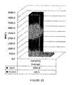
- the table shows the output of the effluent after treatment in the water treatment modular plant.
Landscapes
- Chemical & Material Sciences (AREA)
- Life Sciences & Earth Sciences (AREA)
- Chemical Kinetics & Catalysis (AREA)
- Engineering & Computer Science (AREA)
- Microbiology (AREA)
- Water Supply & Treatment (AREA)
- Organic Chemistry (AREA)
- Hydrology & Water Resources (AREA)
- Environmental & Geological Engineering (AREA)
- Biodiversity & Conservation Biology (AREA)
- Health & Medical Sciences (AREA)
- Molecular Biology (AREA)
- Oil, Petroleum & Natural Gas (AREA)
- General Chemical & Material Sciences (AREA)
- Biological Treatment Of Waste Water (AREA)
- Purification Treatments By Anaerobic Or Anaerobic And Aerobic Bacteria Or Animals (AREA)
- Hydroponics (AREA)
- Treatment Of Biological Wastes In General (AREA)
- Sewage (AREA)
- Removal Of Specific Substances (AREA)
Applications Claiming Priority (2)
| Application Number | Priority Date | Filing Date | Title |
|---|---|---|---|
| MX2011005080A MX338620B (es) | 2011-05-13 | 2011-05-13 | Planta modular para tratamiento de aguas residuales. |
| PCT/MX2012/000053 WO2012158012A2 (fr) | 2011-05-13 | 2012-05-11 | Installation modulaire pour le traitement des eaux usées |
Publications (3)
| Publication Number | Publication Date |
|---|---|
| EP2708515A2 true EP2708515A2 (fr) | 2014-03-19 |
| EP2708515A4 EP2708515A4 (fr) | 2014-11-12 |
| EP2708515B1 EP2708515B1 (fr) | 2019-03-20 |
Family
ID=47177522
Family Applications (1)
| Application Number | Title | Priority Date | Filing Date |
|---|---|---|---|
| EP12785004.8A Not-in-force EP2708515B1 (fr) | 2011-05-13 | 2012-05-11 | Installation modulaire pour le traitement des eaux usées |
Country Status (10)
| Country | Link |
|---|---|
| US (1) | US9890067B2 (fr) |
| EP (1) | EP2708515B1 (fr) |
| BR (1) | BR112013028394A2 (fr) |
| CA (1) | CA2835308C (fr) |
| CO (1) | CO6852055A2 (fr) |
| CR (1) | CR20130595A (fr) |
| GT (1) | GT201300271A (fr) |
| MX (1) | MX338620B (fr) |
| PE (1) | PE20140922A1 (fr) |
| WO (1) | WO2012158012A2 (fr) |
Cited By (5)
| Publication number | Priority date | Publication date | Assignee | Title |
|---|---|---|---|---|
| CN105858900A (zh) * | 2016-05-18 | 2016-08-17 | 东南大学 | 一种模块化格栅式组合人工湿地系统 |
| CN105858901A (zh) * | 2016-05-18 | 2016-08-17 | 东南大学 | 一种预加工插合式组合人工湿地系统 |
| CN106277562A (zh) * | 2016-07-27 | 2017-01-04 | 宁海逸航环保科技有限公司 | 一种新型农村污水处理的工艺流程和方法 |
| CN111115835A (zh) * | 2020-01-15 | 2020-05-08 | 中国水利水电科学研究院 | 一种天然河道污水防治系统和方法及设计方法 |
| CN111995207A (zh) * | 2020-07-07 | 2020-11-27 | 河北鑫达菲塑料制品有限公司 | 一种无渗漏三格化粪池 |
Families Citing this family (13)
| Publication number | Priority date | Publication date | Assignee | Title |
|---|---|---|---|---|
| MX338620B (es) | 2011-05-13 | 2016-03-22 | José Rogelio Pérez Monsrreal | Planta modular para tratamiento de aguas residuales. |
| CN103877775B (zh) | 2012-12-20 | 2017-03-01 | 奥加尼卡有限责任公司 | 用于液体处理尤其是用于盘式废水过滤器设备的过滤器板 |
| CN103214093B (zh) * | 2013-04-09 | 2014-07-02 | 东华大学 | 低c/n生活污水高效脱氮的复合电极水平潜流人工湿地装置 |
| MX364182B (es) * | 2013-07-11 | 2019-03-29 | Martin Munoz Cortes | Fosa septica mejorada, con sistema de filtrado de fluidos con expulsador de gases y extractor de sedimentos dual. |
| US9873607B1 (en) | 2016-07-28 | 2018-01-23 | John Wayen Midnight | Five-gallon water supply systems |
| CR20190041U (es) * | 2016-08-02 | 2019-04-25 | Grupo Rotoplas S A B De C V | Biorreactor anaerobio |
| CN107337312A (zh) * | 2017-07-19 | 2017-11-10 | 中科鼎实环境工程股份有限公司 | 模块化可组卸式人工湿地系统及其潜流人工湿地总成 |
| CN110255811B (zh) * | 2019-05-31 | 2021-12-14 | 浙江水利水电学院 | 一种分散式农村生活污水处理装置及方法 |
| CN111253001A (zh) * | 2020-01-19 | 2020-06-09 | 泉州南京大学环保产业研究院 | 生活污水处理装置及其处理方法 |
| CN112023458B (zh) * | 2020-08-25 | 2021-10-29 | 长江勘测规划设计研究有限责任公司 | 基于双筒的竖流式沉淀池 |
| CN112678992B (zh) * | 2020-12-15 | 2021-08-13 | 吉林建筑大学 | 农田排水回用的方法 |
| CN113185068B (zh) * | 2021-06-10 | 2022-08-09 | 桂林理工大学 | 一种复合式有机废水处理系统 |
| CN115722016B (zh) * | 2022-11-30 | 2025-04-18 | 安徽鑫广环保科技有限公司 | 一种工业污染物的独立水洗处理装置及处理方法 |
Family Cites Families (18)
| Publication number | Priority date | Publication date | Assignee | Title |
|---|---|---|---|---|
| GB521036A (en) | 1938-03-29 | 1940-05-09 | Joseph Darius Griffin | Improvements in sewage sludge digestion |
| US4614584A (en) * | 1985-02-11 | 1986-09-30 | Duca Mark B Di | Distributor box for septic tank systems |
| US4824563A (en) | 1985-12-04 | 1989-04-25 | Kabushiki Kaisha Meidensha | Equipment for treating waste water |
| HU9202203D0 (en) | 1990-01-29 | 1992-12-28 | Yasuyuki Sakurada | Apparatus for purifying sewage water |
| US5531894A (en) * | 1993-11-18 | 1996-07-02 | Orenco Systems, Inc. | Method of treating wastewater |
| US5705057A (en) | 1996-03-25 | 1998-01-06 | Hoffa; Gary | Fluidized bed biological filter assembly for fish tanks |
| FR2775279B1 (fr) | 1998-02-20 | 2000-04-14 | Eparco Sa | Installation et procede specialement destines au traitement des effluents viti-vinicoles |
| US6319396B1 (en) | 1998-05-19 | 2001-11-20 | Robert F. Heagey | Clarifier cone for filtering and separating solids from solution |
| MX213398B (es) | 1998-12-08 | 2002-10-22 | Equipo de tratamiento de aguas residuales domesticas con extraccion de lodos | |
| CN2356028Y (zh) | 1999-01-22 | 1999-12-29 | 刘端华 | 多生物量生物反应器 |
| JP2001079576A (ja) | 1999-09-17 | 2001-03-27 | Kubota Corp | 浄化槽 |
| US6682654B1 (en) | 2000-08-11 | 2004-01-27 | Steve E. Telchuk | Sludge recovery apparatus and method |
| US7297274B2 (en) | 2001-10-24 | 2007-11-20 | University Of Florida Research Foundation, Inc. | Fixed-film anaerobic digestion of flushed waste |
| WO2006091064A1 (fr) | 2005-02-22 | 2006-08-31 | Perez Monsrreal Jose Rogelio | Equipement pour traiter les eaux residuelles de type domestique a sortie lente de fluide |
| SV2008002974A (es) | 2008-07-03 | 2011-08-11 | Larin Carlos Antonio Barillas | Sistema de tratamiento y descontaminacion de agua de desecho domestico |
| MX2009001621A (es) | 2009-02-12 | 2010-08-12 | Jose Rogelio Perez Monsrreal | Tanque septico con filtro autolimpiable y con retroalimentacion para decantacion desnatacion. |
| TWI568687B (zh) * | 2009-06-15 | 2017-02-01 | 沙烏地阿拉伯油品公司 | 包含懸浮系統與多重生物反應器區域的經懸浮介質膜生物反應器系統及方法 |
| MX338620B (es) | 2011-05-13 | 2016-03-22 | José Rogelio Pérez Monsrreal | Planta modular para tratamiento de aguas residuales. |
-
2011
- 2011-05-13 MX MX2011005080A patent/MX338620B/es active IP Right Grant
-
2012
- 2012-05-11 US US14/117,616 patent/US9890067B2/en not_active Expired - Fee Related
- 2012-05-11 CA CA2835308A patent/CA2835308C/fr not_active Expired - Fee Related
- 2012-05-11 PE PE2013002475A patent/PE20140922A1/es not_active Application Discontinuation
- 2012-05-11 WO PCT/MX2012/000053 patent/WO2012158012A2/fr not_active Ceased
- 2012-05-11 BR BR112013028394A patent/BR112013028394A2/pt not_active Application Discontinuation
- 2012-05-11 EP EP12785004.8A patent/EP2708515B1/fr not_active Not-in-force
-
2013
- 2013-11-08 GT GT201300271A patent/GT201300271A/es unknown
- 2013-11-13 CO CO13267076A patent/CO6852055A2/es unknown
- 2013-11-14 CR CR20130595A patent/CR20130595A/es unknown
Cited By (5)
| Publication number | Priority date | Publication date | Assignee | Title |
|---|---|---|---|---|
| CN105858900A (zh) * | 2016-05-18 | 2016-08-17 | 东南大学 | 一种模块化格栅式组合人工湿地系统 |
| CN105858901A (zh) * | 2016-05-18 | 2016-08-17 | 东南大学 | 一种预加工插合式组合人工湿地系统 |
| CN106277562A (zh) * | 2016-07-27 | 2017-01-04 | 宁海逸航环保科技有限公司 | 一种新型农村污水处理的工艺流程和方法 |
| CN111115835A (zh) * | 2020-01-15 | 2020-05-08 | 中国水利水电科学研究院 | 一种天然河道污水防治系统和方法及设计方法 |
| CN111995207A (zh) * | 2020-07-07 | 2020-11-27 | 河北鑫达菲塑料制品有限公司 | 一种无渗漏三格化粪池 |
Also Published As
| Publication number | Publication date |
|---|---|
| EP2708515B1 (fr) | 2019-03-20 |
| US9890067B2 (en) | 2018-02-13 |
| GT201300271A (es) | 2014-08-27 |
| MX338620B (es) | 2016-03-22 |
| CA2835308C (fr) | 2016-06-21 |
| CO6852055A2 (es) | 2014-01-30 |
| PE20140922A1 (es) | 2014-08-13 |
| CR20130595A (es) | 2014-01-14 |
| MX2011005080A (es) | 2012-11-19 |
| CA2835308A1 (fr) | 2012-11-22 |
| WO2012158012A2 (fr) | 2012-11-22 |
| WO2012158012A3 (fr) | 2013-03-28 |
| BR112013028394A2 (pt) | 2017-01-24 |
| EP2708515A4 (fr) | 2014-11-12 |
| US20150014245A1 (en) | 2015-01-15 |
Similar Documents
| Publication | Publication Date | Title |
|---|---|---|
| US9890067B2 (en) | Modular wastewater treatment plant | |
| MX2012002707A (es) | Bioreactor combinado para el tratamiento de aguas residuales, mediante procesos anaerobios, aerobios y anoxicos de degradación de materia orgánica con sistema separador de zonas y captación de biogás, natas y lodos. | |
| CN201834830U (zh) | 一体化污水处理装置 | |
| EP2711064A2 (fr) | Biofiltre pour la digestion des eaux usées | |
| US6569338B1 (en) | Integrated vertical wastewater treatment vessel and method | |
| CN119019060B (zh) | 一种污水处理系统及污水处理方法 | |
| CN104058559A (zh) | 污水处理方法及污水处理系统 | |
| CN107619154A (zh) | 移动式重污染河道水体处理装置 | |
| CN208414137U (zh) | 一种集厌氧、好氧于一体的污水处理装置 | |
| CN212864467U (zh) | 污水处理系统 | |
| CN212669326U (zh) | 一种厌氧反应装置 | |
| CN110713310A (zh) | 一种基于微生物活化海绵铁填料的污水深度处理装置及方法 | |
| CN100351187C (zh) | 污泥厌氧消化方法和消化器 | |
| CN212532667U (zh) | 一种养殖废水处理和沼气回收利用装置 | |
| CN106746352A (zh) | 一种开发区混合废水处理系统 | |
| CN209853935U (zh) | 一种综合集成污水处理装置 | |
| CN209065678U (zh) | 一种垃圾中转站渗滤液处理一体化装备 | |
| CN108455798B (zh) | 一种地埋式医疗污水处理装置 | |
| CN209039269U (zh) | 一种农村生活污水分散式全生态强化治理系统 | |
| CN215627466U (zh) | 一种具有可调出水堰的污水处理装置 | |
| CN109534595A (zh) | 一种农村生活污水处理系统 | |
| CN111807639B (zh) | 一种农村废水生态化处理的塔式反应器及处理方法 | |
| CN203048726U (zh) | 一种小型卧式污水处理装置 | |
| CN114133035B (zh) | 农村用小型一体化污水处理装置 | |
| CN104211196A (zh) | 增氧器、自流增氧生物滤池、自流增氧生态床以及污水处理系统 |
Legal Events
| Date | Code | Title | Description |
|---|---|---|---|
| PUAI | Public reference made under article 153(3) epc to a published international application that has entered the european phase |
Free format text: ORIGINAL CODE: 0009012 |
|
| 17P | Request for examination filed |
Effective date: 20131213 |
|
| AK | Designated contracting states |
Kind code of ref document: A2 Designated state(s): AL AT BE BG CH CY CZ DE DK EE ES FI FR GB GR HR HU IE IS IT LI LT LU LV MC MK MT NL NO PL PT RO RS SE SI SK SM TR |
|
| DAX | Request for extension of the european patent (deleted) | ||
| A4 | Supplementary search report drawn up and despatched |
Effective date: 20141010 |
|
| RIC1 | Information provided on ipc code assigned before grant |
Ipc: C02F 3/06 20060101ALI20141006BHEP Ipc: B01D 21/02 20060101ALI20141006BHEP Ipc: C02F 3/30 20060101AFI20141006BHEP |
|
| STAA | Information on the status of an ep patent application or granted ep patent |
Free format text: STATUS: EXAMINATION IS IN PROGRESS |
|
| 17Q | First examination report despatched |
Effective date: 20180522 |
|
| GRAP | Despatch of communication of intention to grant a patent |
Free format text: ORIGINAL CODE: EPIDOSNIGR1 |
|
| STAA | Information on the status of an ep patent application or granted ep patent |
Free format text: STATUS: GRANT OF PATENT IS INTENDED |
|
| RIC1 | Information provided on ipc code assigned before grant |
Ipc: C02F 11/04 20060101ALN20181004BHEP Ipc: C02F 3/06 20060101ALI20181004BHEP Ipc: C02F 3/28 20060101ALN20181004BHEP Ipc: B01D 21/24 20060101ALN20181004BHEP Ipc: C02F 3/30 20060101AFI20181004BHEP Ipc: B01D 21/02 20060101ALI20181004BHEP Ipc: C02F 3/32 20060101ALN20181004BHEP |
|
| INTG | Intention to grant announced |
Effective date: 20181022 |
|
| GRAS | Grant fee paid |
Free format text: ORIGINAL CODE: EPIDOSNIGR3 |
|
| GRAA | (expected) grant |
Free format text: ORIGINAL CODE: 0009210 |
|
| STAA | Information on the status of an ep patent application or granted ep patent |
Free format text: STATUS: THE PATENT HAS BEEN GRANTED |
|
| AK | Designated contracting states |
Kind code of ref document: B1 Designated state(s): AL AT BE BG CH CY CZ DE DK EE ES FI FR GB GR HR HU IE IS IT LI LT LU LV MC MK MT NL NO PL PT RO RS SE SI SK SM TR |
|
| REG | Reference to a national code |
Ref country code: GB Ref legal event code: FG4D |
|
| REG | Reference to a national code |
Ref country code: CH Ref legal event code: EP |
|
| REG | Reference to a national code |
Ref country code: DE Ref legal event code: R096 Ref document number: 602012058062 Country of ref document: DE |
|
| REG | Reference to a national code |
Ref country code: AT Ref legal event code: REF Ref document number: 1110336 Country of ref document: AT Kind code of ref document: T Effective date: 20190415 |
|
| REG | Reference to a national code |
Ref country code: IE Ref legal event code: FG4D |
|
| REG | Reference to a national code |
Ref country code: NL Ref legal event code: MP Effective date: 20190320 |
|
| PG25 | Lapsed in a contracting state [announced via postgrant information from national office to epo] |
Ref country code: LT Free format text: LAPSE BECAUSE OF FAILURE TO SUBMIT A TRANSLATION OF THE DESCRIPTION OR TO PAY THE FEE WITHIN THE PRESCRIBED TIME-LIMIT Effective date: 20190320 Ref country code: FI Free format text: LAPSE BECAUSE OF FAILURE TO SUBMIT A TRANSLATION OF THE DESCRIPTION OR TO PAY THE FEE WITHIN THE PRESCRIBED TIME-LIMIT Effective date: 20190320 Ref country code: NO Free format text: LAPSE BECAUSE OF FAILURE TO SUBMIT A TRANSLATION OF THE DESCRIPTION OR TO PAY THE FEE WITHIN THE PRESCRIBED TIME-LIMIT Effective date: 20190620 Ref country code: SE Free format text: LAPSE BECAUSE OF FAILURE TO SUBMIT A TRANSLATION OF THE DESCRIPTION OR TO PAY THE FEE WITHIN THE PRESCRIBED TIME-LIMIT Effective date: 20190320 |
|
| REG | Reference to a national code |
Ref country code: LT Ref legal event code: MG4D |
|
| PG25 | Lapsed in a contracting state [announced via postgrant information from national office to epo] |
Ref country code: BG Free format text: LAPSE BECAUSE OF FAILURE TO SUBMIT A TRANSLATION OF THE DESCRIPTION OR TO PAY THE FEE WITHIN THE PRESCRIBED TIME-LIMIT Effective date: 20190620 Ref country code: GR Free format text: LAPSE BECAUSE OF FAILURE TO SUBMIT A TRANSLATION OF THE DESCRIPTION OR TO PAY THE FEE WITHIN THE PRESCRIBED TIME-LIMIT Effective date: 20190621 Ref country code: NL Free format text: LAPSE BECAUSE OF FAILURE TO SUBMIT A TRANSLATION OF THE DESCRIPTION OR TO PAY THE FEE WITHIN THE PRESCRIBED TIME-LIMIT Effective date: 20190320 Ref country code: LV Free format text: LAPSE BECAUSE OF FAILURE TO SUBMIT A TRANSLATION OF THE DESCRIPTION OR TO PAY THE FEE WITHIN THE PRESCRIBED TIME-LIMIT Effective date: 20190320 Ref country code: RS Free format text: LAPSE BECAUSE OF FAILURE TO SUBMIT A TRANSLATION OF THE DESCRIPTION OR TO PAY THE FEE WITHIN THE PRESCRIBED TIME-LIMIT Effective date: 20190320 Ref country code: HR Free format text: LAPSE BECAUSE OF FAILURE TO SUBMIT A TRANSLATION OF THE DESCRIPTION OR TO PAY THE FEE WITHIN THE PRESCRIBED TIME-LIMIT Effective date: 20190320 |
|
| REG | Reference to a national code |
Ref country code: AT Ref legal event code: MK05 Ref document number: 1110336 Country of ref document: AT Kind code of ref document: T Effective date: 20190320 |
|
| PG25 | Lapsed in a contracting state [announced via postgrant information from national office to epo] |
Ref country code: CZ Free format text: LAPSE BECAUSE OF FAILURE TO SUBMIT A TRANSLATION OF THE DESCRIPTION OR TO PAY THE FEE WITHIN THE PRESCRIBED TIME-LIMIT Effective date: 20190320 Ref country code: RO Free format text: LAPSE BECAUSE OF FAILURE TO SUBMIT A TRANSLATION OF THE DESCRIPTION OR TO PAY THE FEE WITHIN THE PRESCRIBED TIME-LIMIT Effective date: 20190320 Ref country code: SK Free format text: LAPSE BECAUSE OF FAILURE TO SUBMIT A TRANSLATION OF THE DESCRIPTION OR TO PAY THE FEE WITHIN THE PRESCRIBED TIME-LIMIT Effective date: 20190320 Ref country code: AL Free format text: LAPSE BECAUSE OF FAILURE TO SUBMIT A TRANSLATION OF THE DESCRIPTION OR TO PAY THE FEE WITHIN THE PRESCRIBED TIME-LIMIT Effective date: 20190320 Ref country code: PT Free format text: LAPSE BECAUSE OF FAILURE TO SUBMIT A TRANSLATION OF THE DESCRIPTION OR TO PAY THE FEE WITHIN THE PRESCRIBED TIME-LIMIT Effective date: 20190720 Ref country code: ES Free format text: LAPSE BECAUSE OF FAILURE TO SUBMIT A TRANSLATION OF THE DESCRIPTION OR TO PAY THE FEE WITHIN THE PRESCRIBED TIME-LIMIT Effective date: 20190320 Ref country code: EE Free format text: LAPSE BECAUSE OF FAILURE TO SUBMIT A TRANSLATION OF THE DESCRIPTION OR TO PAY THE FEE WITHIN THE PRESCRIBED TIME-LIMIT Effective date: 20190320 Ref country code: IT Free format text: LAPSE BECAUSE OF FAILURE TO SUBMIT A TRANSLATION OF THE DESCRIPTION OR TO PAY THE FEE WITHIN THE PRESCRIBED TIME-LIMIT Effective date: 20190320 |
|
| PG25 | Lapsed in a contracting state [announced via postgrant information from national office to epo] |
Ref country code: PL Free format text: LAPSE BECAUSE OF FAILURE TO SUBMIT A TRANSLATION OF THE DESCRIPTION OR TO PAY THE FEE WITHIN THE PRESCRIBED TIME-LIMIT Effective date: 20190320 Ref country code: SM Free format text: LAPSE BECAUSE OF FAILURE TO SUBMIT A TRANSLATION OF THE DESCRIPTION OR TO PAY THE FEE WITHIN THE PRESCRIBED TIME-LIMIT Effective date: 20190320 |
|
| REG | Reference to a national code |
Ref country code: DE Ref legal event code: R119 Ref document number: 602012058062 Country of ref document: DE |
|
| REG | Reference to a national code |
Ref country code: CH Ref legal event code: PL |
|
| PG25 | Lapsed in a contracting state [announced via postgrant information from national office to epo] |
Ref country code: IS Free format text: LAPSE BECAUSE OF FAILURE TO SUBMIT A TRANSLATION OF THE DESCRIPTION OR TO PAY THE FEE WITHIN THE PRESCRIBED TIME-LIMIT Effective date: 20190720 Ref country code: AT Free format text: LAPSE BECAUSE OF FAILURE TO SUBMIT A TRANSLATION OF THE DESCRIPTION OR TO PAY THE FEE WITHIN THE PRESCRIBED TIME-LIMIT Effective date: 20190320 |
|
| PLBE | No opposition filed within time limit |
Free format text: ORIGINAL CODE: 0009261 |
|
| STAA | Information on the status of an ep patent application or granted ep patent |
Free format text: STATUS: NO OPPOSITION FILED WITHIN TIME LIMIT |
|
| PG25 | Lapsed in a contracting state [announced via postgrant information from national office to epo] |
Ref country code: LI Free format text: LAPSE BECAUSE OF NON-PAYMENT OF DUE FEES Effective date: 20190531 Ref country code: MC Free format text: LAPSE BECAUSE OF FAILURE TO SUBMIT A TRANSLATION OF THE DESCRIPTION OR TO PAY THE FEE WITHIN THE PRESCRIBED TIME-LIMIT Effective date: 20190320 Ref country code: DK Free format text: LAPSE BECAUSE OF FAILURE TO SUBMIT A TRANSLATION OF THE DESCRIPTION OR TO PAY THE FEE WITHIN THE PRESCRIBED TIME-LIMIT Effective date: 20190320 Ref country code: CH Free format text: LAPSE BECAUSE OF NON-PAYMENT OF DUE FEES Effective date: 20190531 |
|
| REG | Reference to a national code |
Ref country code: BE Ref legal event code: MM Effective date: 20190531 |
|
| 26N | No opposition filed |
Effective date: 20200102 |
|
| GBPC | Gb: european patent ceased through non-payment of renewal fee |
Effective date: 20190620 |
|
| PG25 | Lapsed in a contracting state [announced via postgrant information from national office to epo] |
Ref country code: SI Free format text: LAPSE BECAUSE OF FAILURE TO SUBMIT A TRANSLATION OF THE DESCRIPTION OR TO PAY THE FEE WITHIN THE PRESCRIBED TIME-LIMIT Effective date: 20190320 Ref country code: LU Free format text: LAPSE BECAUSE OF NON-PAYMENT OF DUE FEES Effective date: 20190511 |
|
| PG25 | Lapsed in a contracting state [announced via postgrant information from national office to epo] |
Ref country code: TR Free format text: LAPSE BECAUSE OF FAILURE TO SUBMIT A TRANSLATION OF THE DESCRIPTION OR TO PAY THE FEE WITHIN THE PRESCRIBED TIME-LIMIT Effective date: 20190320 |
|
| PG25 | Lapsed in a contracting state [announced via postgrant information from national office to epo] |
Ref country code: DE Free format text: LAPSE BECAUSE OF NON-PAYMENT OF DUE FEES Effective date: 20191203 Ref country code: GB Free format text: LAPSE BECAUSE OF NON-PAYMENT OF DUE FEES Effective date: 20190620 Ref country code: IE Free format text: LAPSE BECAUSE OF NON-PAYMENT OF DUE FEES Effective date: 20190511 |
|
| PG25 | Lapsed in a contracting state [announced via postgrant information from national office to epo] |
Ref country code: BE Free format text: LAPSE BECAUSE OF NON-PAYMENT OF DUE FEES Effective date: 20190531 |
|
| PG25 | Lapsed in a contracting state [announced via postgrant information from national office to epo] |
Ref country code: FR Free format text: LAPSE BECAUSE OF NON-PAYMENT OF DUE FEES Effective date: 20190520 |
|
| PG25 | Lapsed in a contracting state [announced via postgrant information from national office to epo] |
Ref country code: CY Free format text: LAPSE BECAUSE OF FAILURE TO SUBMIT A TRANSLATION OF THE DESCRIPTION OR TO PAY THE FEE WITHIN THE PRESCRIBED TIME-LIMIT Effective date: 20190320 |
|
| PG25 | Lapsed in a contracting state [announced via postgrant information from national office to epo] |
Ref country code: MT Free format text: LAPSE BECAUSE OF FAILURE TO SUBMIT A TRANSLATION OF THE DESCRIPTION OR TO PAY THE FEE WITHIN THE PRESCRIBED TIME-LIMIT Effective date: 20190320 Ref country code: HU Free format text: LAPSE BECAUSE OF FAILURE TO SUBMIT A TRANSLATION OF THE DESCRIPTION OR TO PAY THE FEE WITHIN THE PRESCRIBED TIME-LIMIT; INVALID AB INITIO Effective date: 20120511 |
|
| PG25 | Lapsed in a contracting state [announced via postgrant information from national office to epo] |
Ref country code: MK Free format text: LAPSE BECAUSE OF FAILURE TO SUBMIT A TRANSLATION OF THE DESCRIPTION OR TO PAY THE FEE WITHIN THE PRESCRIBED TIME-LIMIT Effective date: 20190320 |