EP2708680A2 - Ouvrage réservoir et procédé d'étanchéification de celui-ci - Google Patents
Ouvrage réservoir et procédé d'étanchéification de celui-ci Download PDFInfo
- Publication number
- EP2708680A2 EP2708680A2 EP13004551.1A EP13004551A EP2708680A2 EP 2708680 A2 EP2708680 A2 EP 2708680A2 EP 13004551 A EP13004551 A EP 13004551A EP 2708680 A2 EP2708680 A2 EP 2708680A2
- Authority
- EP
- European Patent Office
- Prior art keywords
- tank
- vacuum
- plate
- tight
- segment
- Prior art date
- Legal status (The legal status is an assumption and is not a legal conclusion. Google has not performed a legal analysis and makes no representation as to the accuracy of the status listed.)
- Withdrawn
Links
- 238000000034 method Methods 0.000 title claims abstract description 132
- 238000007789 sealing Methods 0.000 title claims abstract description 30
- 238000012544 monitoring process Methods 0.000 claims abstract description 175
- 239000007788 liquid Substances 0.000 claims abstract description 97
- XEEYBQQBJWHFJM-UHFFFAOYSA-N Iron Chemical compound [Fe] XEEYBQQBJWHFJM-UHFFFAOYSA-N 0.000 claims description 567
- 229910052742 iron Inorganic materials 0.000 claims description 280
- 238000003466 welding Methods 0.000 claims description 188
- XKRFYHLGVUSROY-UHFFFAOYSA-N Argon Chemical compound [Ar] XKRFYHLGVUSROY-UHFFFAOYSA-N 0.000 claims description 166
- 238000010276 construction Methods 0.000 claims description 146
- 229910000831 Steel Inorganic materials 0.000 claims description 124
- 239000010959 steel Substances 0.000 claims description 124
- 238000000926 separation method Methods 0.000 claims description 115
- 229910052786 argon Inorganic materials 0.000 claims description 83
- 229910052751 metal Inorganic materials 0.000 claims description 76
- 239000002184 metal Substances 0.000 claims description 76
- 239000004567 concrete Substances 0.000 claims description 70
- 239000000463 material Substances 0.000 claims description 66
- 230000003014 reinforcing effect Effects 0.000 claims description 66
- 239000004744 fabric Substances 0.000 claims description 55
- 239000007789 gas Substances 0.000 claims description 44
- 239000003365 glass fiber Substances 0.000 claims description 40
- 238000011010 flushing procedure Methods 0.000 claims description 37
- 229910052782 aluminium Inorganic materials 0.000 claims description 25
- XAGFODPZIPBFFR-UHFFFAOYSA-N aluminium Chemical compound [Al] XAGFODPZIPBFFR-UHFFFAOYSA-N 0.000 claims description 25
- 125000006850 spacer group Chemical group 0.000 claims description 25
- 230000015572 biosynthetic process Effects 0.000 claims description 24
- 239000011888 foil Substances 0.000 claims description 23
- 239000007769 metal material Substances 0.000 claims description 23
- 238000010926 purge Methods 0.000 claims description 22
- 230000007704 transition Effects 0.000 claims description 19
- 239000010802 sludge Substances 0.000 claims description 15
- 238000009434 installation Methods 0.000 claims description 13
- 230000000284 resting effect Effects 0.000 claims description 9
- 239000007787 solid Substances 0.000 claims description 8
- 239000002283 diesel fuel Substances 0.000 claims description 7
- 230000002787 reinforcement Effects 0.000 claims description 4
- 238000011176 pooling Methods 0.000 claims 2
- 239000010410 layer Substances 0.000 description 298
- 238000012360 testing method Methods 0.000 description 68
- 230000008569 process Effects 0.000 description 55
- 238000007667 floating Methods 0.000 description 34
- 210000001503 joint Anatomy 0.000 description 25
- 238000004519 manufacturing process Methods 0.000 description 19
- 239000000344 soap Substances 0.000 description 12
- 239000011152 fibreglass Substances 0.000 description 11
- 239000007921 spray Substances 0.000 description 11
- 239000010935 stainless steel Substances 0.000 description 11
- 229910001220 stainless steel Inorganic materials 0.000 description 11
- 241001295925 Gegenes Species 0.000 description 10
- 230000035939 shock Effects 0.000 description 9
- 230000008878 coupling Effects 0.000 description 8
- 238000010168 coupling process Methods 0.000 description 8
- 238000005859 coupling reaction Methods 0.000 description 8
- 238000013461 design Methods 0.000 description 8
- 239000000203 mixture Substances 0.000 description 8
- 239000000126 substance Substances 0.000 description 8
- 229910001335 Galvanized steel Inorganic materials 0.000 description 7
- 239000008397 galvanized steel Substances 0.000 description 7
- 239000007864 aqueous solution Substances 0.000 description 6
- 238000000576 coating method Methods 0.000 description 6
- 230000007547 defect Effects 0.000 description 6
- 230000008439 repair process Effects 0.000 description 6
- 239000011248 coating agent Substances 0.000 description 5
- 238000007796 conventional method Methods 0.000 description 5
- 239000003063 flame retardant Substances 0.000 description 5
- 239000011148 porous material Substances 0.000 description 5
- 238000005067 remediation Methods 0.000 description 5
- WFKWXMTUELFFGS-UHFFFAOYSA-N tungsten Chemical compound [W] WFKWXMTUELFFGS-UHFFFAOYSA-N 0.000 description 5
- 229910052721 tungsten Inorganic materials 0.000 description 5
- 239000010937 tungsten Substances 0.000 description 5
- 238000006243 chemical reaction Methods 0.000 description 4
- 239000002131 composite material Substances 0.000 description 4
- 238000005520 cutting process Methods 0.000 description 4
- 238000001514 detection method Methods 0.000 description 4
- 239000000945 filler Substances 0.000 description 4
- -1 fine gravel Substances 0.000 description 4
- 239000006260 foam Substances 0.000 description 4
- 238000012806 monitoring device Methods 0.000 description 4
- 230000002093 peripheral effect Effects 0.000 description 4
- 239000002689 soil Substances 0.000 description 4
- 229910000851 Alloy steel Inorganic materials 0.000 description 3
- 229910000640 Fe alloy Inorganic materials 0.000 description 3
- 244000089486 Phragmites australis subsp australis Species 0.000 description 3
- 239000002390 adhesive tape Substances 0.000 description 3
- 239000011230 binding agent Substances 0.000 description 3
- 239000004568 cement Substances 0.000 description 3
- 150000001875 compounds Chemical class 0.000 description 3
- 239000010779 crude oil Substances 0.000 description 3
- 239000000446 fuel Substances 0.000 description 3
- 239000000383 hazardous chemical Substances 0.000 description 3
- 231100000206 health hazard Toxicity 0.000 description 3
- 238000005304 joining Methods 0.000 description 3
- 238000005259 measurement Methods 0.000 description 3
- 239000004570 mortar (masonry) Substances 0.000 description 3
- 239000003921 oil Substances 0.000 description 3
- 238000012545 processing Methods 0.000 description 3
- 239000011241 protective layer Substances 0.000 description 3
- 238000005488 sandblasting Methods 0.000 description 3
- 238000003860 storage Methods 0.000 description 3
- RNFJDJUURJAICM-UHFFFAOYSA-N 2,2,4,4,6,6-hexaphenoxy-1,3,5-triaza-2$l^{5},4$l^{5},6$l^{5}-triphosphacyclohexa-1,3,5-triene Chemical compound N=1P(OC=2C=CC=CC=2)(OC=2C=CC=CC=2)=NP(OC=2C=CC=CC=2)(OC=2C=CC=CC=2)=NP=1(OC=1C=CC=CC=1)OC1=CC=CC=C1 RNFJDJUURJAICM-UHFFFAOYSA-N 0.000 description 2
- CPLXHLVBOLITMK-UHFFFAOYSA-N Magnesium oxide Chemical compound [Mg]=O CPLXHLVBOLITMK-UHFFFAOYSA-N 0.000 description 2
- 238000005299 abrasion Methods 0.000 description 2
- 230000009471 action Effects 0.000 description 2
- 239000000654 additive Substances 0.000 description 2
- 238000005452 bending Methods 0.000 description 2
- 238000005422 blasting Methods 0.000 description 2
- OSGAYBCDTDRGGQ-UHFFFAOYSA-L calcium sulfate Chemical compound [Ca+2].[O-]S([O-])(=O)=O OSGAYBCDTDRGGQ-UHFFFAOYSA-L 0.000 description 2
- 235000014113 dietary fatty acids Nutrition 0.000 description 2
- 239000000194 fatty acid Substances 0.000 description 2
- 229930195729 fatty acid Natural products 0.000 description 2
- 150000004665 fatty acids Chemical class 0.000 description 2
- 239000000835 fiber Substances 0.000 description 2
- 239000011521 glass Substances 0.000 description 2
- 239000010440 gypsum Substances 0.000 description 2
- 229910052602 gypsum Inorganic materials 0.000 description 2
- 230000036541 health Effects 0.000 description 2
- 239000011261 inert gas Substances 0.000 description 2
- 238000007689 inspection Methods 0.000 description 2
- 239000006193 liquid solution Substances 0.000 description 2
- 239000011159 matrix material Substances 0.000 description 2
- 230000035699 permeability Effects 0.000 description 2
- 239000004033 plastic Substances 0.000 description 2
- 229920003023 plastic Polymers 0.000 description 2
- 238000002360 preparation method Methods 0.000 description 2
- 239000002994 raw material Substances 0.000 description 2
- 238000009419 refurbishment Methods 0.000 description 2
- 238000004904 shortening Methods 0.000 description 2
- 229920001169 thermoplastic Polymers 0.000 description 2
- 229920001187 thermosetting polymer Polymers 0.000 description 2
- 239000004416 thermosoftening plastic Substances 0.000 description 2
- WRIDQFICGBMAFQ-UHFFFAOYSA-N (E)-8-Octadecenoic acid Natural products CCCCCCCCCC=CCCCCCCC(O)=O WRIDQFICGBMAFQ-UHFFFAOYSA-N 0.000 description 1
- LQJBNNIYVWPHFW-UHFFFAOYSA-N 20:1omega9c fatty acid Natural products CCCCCCCCCCC=CCCCCCCCC(O)=O LQJBNNIYVWPHFW-UHFFFAOYSA-N 0.000 description 1
- QSBYPNXLFMSGKH-UHFFFAOYSA-N 9-Heptadecensaeure Natural products CCCCCCCC=CCCCCCCCC(O)=O QSBYPNXLFMSGKH-UHFFFAOYSA-N 0.000 description 1
- 239000004604 Blowing Agent Substances 0.000 description 1
- 235000013162 Cocos nucifera Nutrition 0.000 description 1
- 244000060011 Cocos nucifera Species 0.000 description 1
- 241000196324 Embryophyta Species 0.000 description 1
- ZQPPMHVWECSIRJ-UHFFFAOYSA-N Oleic acid Natural products CCCCCCCCC=CCCCCCCCC(O)=O ZQPPMHVWECSIRJ-UHFFFAOYSA-N 0.000 description 1
- 239000005642 Oleic acid Substances 0.000 description 1
- ISWSIDIOOBJBQZ-UHFFFAOYSA-N Phenol Chemical compound OC1=CC=CC=C1 ISWSIDIOOBJBQZ-UHFFFAOYSA-N 0.000 description 1
- 239000004952 Polyamide Substances 0.000 description 1
- 239000004721 Polyphenylene oxide Substances 0.000 description 1
- ZLMJMSJWJFRBEC-UHFFFAOYSA-N Potassium Chemical compound [K] ZLMJMSJWJFRBEC-UHFFFAOYSA-N 0.000 description 1
- 238000009825 accumulation Methods 0.000 description 1
- 239000013543 active substance Substances 0.000 description 1
- 230000000996 additive effect Effects 0.000 description 1
- 229910045601 alloy Inorganic materials 0.000 description 1
- 239000000956 alloy Substances 0.000 description 1
- 150000008064 anhydrides Chemical class 0.000 description 1
- 239000004566 building material Substances 0.000 description 1
- 150000008280 chlorinated hydrocarbons Chemical class 0.000 description 1
- 230000007423 decrease Effects 0.000 description 1
- 230000006735 deficit Effects 0.000 description 1
- 238000009795 derivation Methods 0.000 description 1
- 238000011161 development Methods 0.000 description 1
- 230000018109 developmental process Effects 0.000 description 1
- 230000000694 effects Effects 0.000 description 1
- 230000007613 environmental effect Effects 0.000 description 1
- 239000003822 epoxy resin Substances 0.000 description 1
- 239000007849 furan resin Substances 0.000 description 1
- 238000009499 grossing Methods 0.000 description 1
- LNEPOXFFQSENCJ-UHFFFAOYSA-N haloperidol Chemical compound C1CC(O)(C=2C=CC(Cl)=CC=2)CCN1CCCC(=O)C1=CC=C(F)C=C1 LNEPOXFFQSENCJ-UHFFFAOYSA-N 0.000 description 1
- 238000010438 heat treatment Methods 0.000 description 1
- 230000001771 impaired effect Effects 0.000 description 1
- 239000007924 injection Substances 0.000 description 1
- 238000002347 injection Methods 0.000 description 1
- QXJSBBXBKPUZAA-UHFFFAOYSA-N isooleic acid Natural products CCCCCCCC=CCCCCCCCCC(O)=O QXJSBBXBKPUZAA-UHFFFAOYSA-N 0.000 description 1
- 231100000518 lethal Toxicity 0.000 description 1
- 230000001665 lethal effect Effects 0.000 description 1
- 239000000395 magnesium oxide Substances 0.000 description 1
- 235000012054 meals Nutrition 0.000 description 1
- 238000003801 milling Methods 0.000 description 1
- 230000007935 neutral effect Effects 0.000 description 1
- ZQPPMHVWECSIRJ-KTKRTIGZSA-N oleic acid Chemical compound CCCCCCCC\C=C/CCCCCCCC(O)=O ZQPPMHVWECSIRJ-KTKRTIGZSA-N 0.000 description 1
- 239000003415 peat Substances 0.000 description 1
- 239000005011 phenolic resin Substances 0.000 description 1
- 229920002647 polyamide Polymers 0.000 description 1
- 229920000515 polycarbonate Polymers 0.000 description 1
- 239000004417 polycarbonate Substances 0.000 description 1
- 229920000647 polyepoxide Polymers 0.000 description 1
- 229920000642 polymer Polymers 0.000 description 1
- 229920006380 polyphenylene oxide Polymers 0.000 description 1
- 229910052700 potassium Inorganic materials 0.000 description 1
- 239000011591 potassium Substances 0.000 description 1
- 230000001681 protective effect Effects 0.000 description 1
- 238000009418 renovation Methods 0.000 description 1
- 238000009420 retrofitting Methods 0.000 description 1
- 239000004576 sand Substances 0.000 description 1
- 238000009991 scouring Methods 0.000 description 1
- 239000002893 slag Substances 0.000 description 1
- 239000000243 solution Substances 0.000 description 1
- 239000002904 solvent Substances 0.000 description 1
- 239000004575 stone Substances 0.000 description 1
- 210000004243 sweat Anatomy 0.000 description 1
- 229920003002 synthetic resin Polymers 0.000 description 1
- 239000000057 synthetic resin Substances 0.000 description 1
- 238000012549 training Methods 0.000 description 1
- 229920006337 unsaturated polyester resin Polymers 0.000 description 1
- XLYOFNOQVPJJNP-UHFFFAOYSA-N water Substances O XLYOFNOQVPJJNP-UHFFFAOYSA-N 0.000 description 1
Images










Classifications
-
- B—PERFORMING OPERATIONS; TRANSPORTING
- B65—CONVEYING; PACKING; STORING; HANDLING THIN OR FILAMENTARY MATERIAL
- B65D—CONTAINERS FOR STORAGE OR TRANSPORT OF ARTICLES OR MATERIALS, e.g. BAGS, BARRELS, BOTTLES, BOXES, CANS, CARTONS, CRATES, DRUMS, JARS, TANKS, HOPPERS, FORWARDING CONTAINERS; ACCESSORIES, CLOSURES, OR FITTINGS THEREFOR; PACKAGING ELEMENTS; PACKAGES
- B65D90/00—Component parts, details or accessories for large containers
- B65D90/48—Arrangements of indicating or measuring devices
- B65D90/50—Arrangements of indicating or measuring devices of leakage-indicating devices
- B65D90/501—Arrangements of indicating or measuring devices of leakage-indicating devices comprising hollow spaces within walls
- B65D90/503—Arrangements of indicating or measuring devices of leakage-indicating devices comprising hollow spaces within walls under pressure or vacuum
-
- B—PERFORMING OPERATIONS; TRANSPORTING
- B65—CONVEYING; PACKING; STORING; HANDLING THIN OR FILAMENTARY MATERIAL
- B65D—CONTAINERS FOR STORAGE OR TRANSPORT OF ARTICLES OR MATERIALS, e.g. BAGS, BARRELS, BOTTLES, BOXES, CANS, CARTONS, CRATES, DRUMS, JARS, TANKS, HOPPERS, FORWARDING CONTAINERS; ACCESSORIES, CLOSURES, OR FITTINGS THEREFOR; PACKAGING ELEMENTS; PACKAGES
- B65D90/00—Component parts, details or accessories for large containers
- B65D90/02—Wall construction
- B65D90/022—Laminated structures
-
- E—FIXED CONSTRUCTIONS
- E04—BUILDING
- E04H—BUILDINGS OR LIKE STRUCTURES FOR PARTICULAR PURPOSES; SWIMMING OR SPLASH BATHS OR POOLS; MASTS; FENCING; TENTS OR CANOPIES, IN GENERAL
- E04H7/00—Construction or assembling of bulk storage containers employing civil engineering techniques in situ or off the site
- E04H7/02—Containers for fluids or gases; Supports therefor
- E04H7/04—Containers for fluids or gases; Supports therefor mainly of metal
- E04H7/06—Containers for fluids or gases; Supports therefor mainly of metal with vertical axis
-
- G—PHYSICS
- G01—MEASURING; TESTING
- G01M—TESTING STATIC OR DYNAMIC BALANCE OF MACHINES OR STRUCTURES; TESTING OF STRUCTURES OR APPARATUS, NOT OTHERWISE PROVIDED FOR
- G01M3/00—Investigating fluid-tightness of structures
- G01M3/02—Investigating fluid-tightness of structures by using fluid or vacuum
- G01M3/26—Investigating fluid-tightness of structures by using fluid or vacuum by measuring rate of loss or gain of fluid, e.g. by pressure-responsive devices, by flow detectors
- G01M3/32—Investigating fluid-tightness of structures by using fluid or vacuum by measuring rate of loss or gain of fluid, e.g. by pressure-responsive devices, by flow detectors for containers, e.g. radiators
- G01M3/3236—Investigating fluid-tightness of structures by using fluid or vacuum by measuring rate of loss or gain of fluid, e.g. by pressure-responsive devices, by flow detectors for containers, e.g. radiators by monitoring the interior space of the containers
- G01M3/3263—Investigating fluid-tightness of structures by using fluid or vacuum by measuring rate of loss or gain of fluid, e.g. by pressure-responsive devices, by flow detectors for containers, e.g. radiators by monitoring the interior space of the containers using a differential pressure detector
Definitions
- the present invention relates to a tank construction for containing liquids, such as organic or aqueous liquids, with metallic materials, and a reliable method for sealing a tank construction with a chamber monitoring system with vacuum monitoring.
- the term “tank construction” also means the conventional cylindrical tank container with a large diameter, which serves for the storage of large quantities of liquids, such as liquid, organic liquids, flammable or aqueous substances.
- the conventional tank construction may contain metal materials, e.g. Iron or steel alloys, have or be produced with such; Also, the conventional tank construction may not contain metal materials, e.g. plastic-like materials, comprise or be produced with such.
- tank construction is also understood in the sense of the invention to be any, regardless of the size, shape and nature, such as any tank container for storing or transporting fuels, in particular a tank container, oil refineries, oil tankers, stored in the crude oil in large quantities or can be transported.
- the tank container also comprises a tank bottom and a tank shell projecting from the tank shell, which limit the interior thereof.
- the tank bottom may be formed as a flat bottom for providing a conventional flat-bottomed tank.
- the storage of large quantities of liquid, combustible substances is required in the chemical and petrochemical industry and at transhipment points for the transport of such substances.
- crude oils or crude oil distillates which are used, for example, as fuels or fuels, but also as solvents or as raw materials or partially refined raw materials for further chemical conversions.
- the requirement of storing large quantities of liquid, combustible materials is recognized in order to ensure continuous operation of the process plants and the supply of users with these substances even in times of crisis guarantee.
- the conventional tank construction can absorb corrosive effects on the bottom of the tank and thus lead to leaks, so that welds and metal layers that form the tank bottom of the large tank are to be examined at regular intervals.
- the conventional tank construction can e.g. as a so-called flat-bottom tank construction have a inside coated with a protective layer steel floor, on the inside with a concrete layer or coated with a layer of glass fiber reinforced plastic-like material tank bottom.
- various remediation methods have been carried out in the prior art.
- One conventional remediation process involved removing and disposing the sheet applied to the inside of the tank bottom with the glass fiber reinforced plastic-like material, and then installing a new sheet of steel material thickness, such as 7.0mm, in conventional tank structures with the tank bottom surface coating.
- Disadvantages of this refurbishment process included disassembling and disposing of the old layer of glass fiber reinforced plastic-like material, resulting in a disproportionate amount of time and expense, and an enormous amount of hard-to-predict costing the user in advance, Occurrence of high disposal costs for the disposal of the old remote layer with the glass fiber reinforced plastic-like material, Conducting the sandblasting of the old tank bottom, which resulted in an increase in the cost of blasting and blasting, subsequent checking of the old existing tank bottom for leaks with the resulting costs for the test, Carrying out repairs on the old tank bottom with the resulting high costs with subsequent inspections for tightness of the same, Producing inevitable conditional mounting holes in the tank shell for the purpose of introducing large-scale floor panels in the interior of the tank construction, additional installation of a new tank bottom for the production of a vacuum-monitored double floor and high costs for the new steel floor and testing costs, Performing the repairs of the mounting holes in the tank shell, Accumulation of material, welding and testing costs, Applying
- Another conventional remediation method involves the introduction of a new steel double bottom, e.g. with a material thickness of 7.00 mm, with an additional surface coating on the old located in the interior of the tank structure floor with the glass fiber reinforced plastic-like material.
- the arc In TIG welding, it is possible for the arc to be ignited between an electrode, such as a non-consumable tungsten electrode, and the workpiece.
- an electrode such as a non-consumable tungsten electrode
- the arc burns between a sheathed metal electrode and the workpiece capable of reflowing the workpiece and / or electrode.
- welding or welding with electrode or electrically can also be understood as meaning arc welding, arc welding or manual arc welding or the like.
- the glass fiber reinforced plastic-like material Due to the large number of welds in the floor area, the glass fiber reinforced plastic-like material is exposed to the high heat, so that there is a very significant risk of fire and can be a further disadvantage for humans lethal welding gases.
- Another conventional method involves applying a concrete layer to the tank floor comprising a layer of fiberglass-reinforced plastic-like material and retrofitting a steel double floor, eg 7.00 mm thick, to provide a vacuum-controllable and vacuum-controllable space.
- the disadvantages of this conventional method step are substantially the same as the disadvantages of the previous conventional methods, besides disadvantages such as additional costs for the introduction of the concrete layer, Shortening of the floating roof feet due to the increase of the floating roof feet facing new tank bottom on the smaller spacing of the floating roof feet to the top of the new tank bottom and additional costs for the conversion of measuring systems, such as tilting tables, single-pipe measurements from the roof, nozzles, internal pipelines, as the tank bottom level increases significantly due to the installation of the additional concrete layer and the new double floor.
- the leak test of the upper edge segment was tested by means of overpressure (2-3 bar) and skimming with a conventional leak detection spray. In this type of testing there is a risk that the welds tear off. Due to the high overpressure, there is also a high risk that errors in the seams can not be detected, since the leak detection spray does not continuously generate bubbles through the defect, but is blown away.
- the object of the invention is to provide a tank construction and a method which do not realize the disadvantages of the prior art.
- the tank construction to be provided should have a raised floor with a verifiable, for example, vacuum-verifiable and monitorable, space, which does not avoid the removal of the existing layers on the tank bottom, such as the removal of the glass fiber reinforced plastic-like material.
- the height mobility of the floating roof feet of the floating roof of the conventional tank construction should not be limited and no adjustment of the same be required.
- the chamber monitoring arrangement to be provided should have a high stability, so that the installation of the chamber monitoring arrangement in the tank construction the Stability of the tank shell and thus that of the tank construction is not impaired, in contrast to conventional sealing devices to reduce the force applied to the tank shell such that after installation of the same no occurrence of cracks and crevices in the tank shell, in the transition region of tank shell to tank bottom and in the tank bottom can be observed.
- the time for the implementation of the rehabilitation in order to provide a new tightness of the tank construction should be as short as possible in order to quickly supply the tank structure of the re-storage of liquids.
- the invention relates to a chamber monitoring assembly for installation in a tank construction for liquids, in particular for organic liquids, eg diesel fuels, preferably with one or more metallic materials, which, preferably a hollow cylindrical tank container with a, preferably supported against a solid surface, tank bottom and one of the tank bottom projecting, preferably hollow cylindrical tank shell, the chamber monitoring arrangement comprises at least one edge segment and at least one ground segment and at least one gas- and liquid-tight intermediate space as a monitoring chamber for monitoring the tightness of the chamber monitoring arrangement to liquids, which is characterized in that the edge segment and / or the ground segment have at least one monitoring chamber, preferably the edge segment and the bottom segment are suitable for resting on or against the inside of the tank bottom, the edge segment with the bottom segment vacuum-tight connected, preferably vacuum-tight welded, is Preferably, the edge segment with the tank shell of the tank container vacuum-tight connectable, preferably welded, is.
- the invention is also directed to a tank construction with a chamber monitoring arrangement for liquids, in particular for organic liquids, eg diesel fuels, preferably with metallic materials, one, preferably hollow cylindrical, tank container with a, preferably supported against a solid surface, tank bottom and one of the tank bottom projecting, preferably hollow cylindrical tank shell, which is characterized in that the chamber monitoring arrangement comprises at least one edge segment and at least one ground segment and at least one gas-tight and liquid-tight intermediate space as a monitoring chamber for monitoring the tightness of the tank construction with respect to liquids, the edge segment and / or the ground segment each have at least one monitoring chamber, the edge segment or part thereof and / or the floor segment rest on the inside of the tank bottom, the edge segment is attached against the inside of the tank shell, the edge segment and the bottom segment, preferably connected to one another in an edge segment-bottom segment transition region, connected in a vacuum-tight manner, preferably vacuum-sealed, are the edge segment vacuum-tight connected to the tank shell, preferably welded, is.
- Another object of the invention is directed to a tank construction with a chamber monitoring arrangement, which comprises at least one edge segment and at least one ground segment and at least one gas- and liquid-tight space as a monitoring chamber for monitoring the tightness of the tank structure to liquids, wherein the edge segment or a part thereof the Space limited, the floor segment or a part of it delimits the gap, the edge segment is connected to the tank jacket in a vacuum-tight manner, preferably welded, is the edge segment is connected to the bottom segment in a vacuum-tight manner, the edge segment comprise at least one lying plate and / or at least one standing plate and / or the bottom segment at least one base plate, at least one lying plate and / or at least one standing plate are kept at a distance from the inside of the tank jacket and / or the inside of the tank bottom, at least one bottom plate is arranged at a distance from the inside of the tank bottom or to a further bottom plate, preferably the bottom plate and / or the further bottom plate are aligned parallel to the inside of the tank bottom
- the invention is also based on the use of the chamber monitoring arrangement of a double-walled edge segment and a double-edged bottom segment.
- the invention is based on the use of edge segments, which may be circular in plan view, such as annular or oval, or angular or part-circular in plan view, such as semicircular or quarter-circular, formed and vacuum-tight, preferably vacuum-tight welded, may be, can surround the monitoring chambers in a vacuum-tight manner, which are vacuum-tight welded to the tank shell, which may include as lower parts lower plates and lower floor plates and as upper parts upper plates and upper floor plates and can close or limit vacuum-tight one or more spaces as monitoring chambers with these sheets:
- the lower lying plate can rest on the tank bottom or on a concrete layer inclined toward the tank bottom or toward the center of the circle of the tank bottom, wherein the concrete layer may be applied on a surface applied to the tank shell in the edge region of the tank bottom on a layer applied to the tank bottom with a glass-fiber-reinforced plastic-like material, in the direction of the tank bottom or towards the center of the circular tank bottom inclined or placed on the tank bottom lower floor panel can be set against the tank shell as well as against the lower deck plate to form attachment points, the upper deck plate inclined towards the tank bottom or inclined toward the center of the tank bottom can be set against the lower deck plate and against spacers arranged on the lower deck plate to form attachment points, the upper standing plate, which is inclined in the direction of the tank bottom or inclined toward the center of the tank bottom, can be set against the tank shell as well as against the upper lying plate to form attachment points, and the attachment points can be vacuum-tight welded to form the vacuum-tight gap.
- the tank construction according to the invention may also comprise only a vacuum-tight space as a monitoring chamber, wherein the edge segment at least one lying plate and the bottom segment comprise at least one floor panel, the edge segment is vacuum-tightly connected to the ground segment, the edge segment or a part thereof and the ground segment or a part thereof Limit space, the edge segment is connected to the tank jacket vacuum-tight, at least one baffle plate and / or at least one standing plate at a distance from the inside of the tank shell and / or the inside of the tank bottom and the bottom plate are arranged at a distance from the inside of the tank bottom.
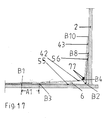
- the edge segment comprises a longitudinal section L-shaped lying plate and a floor panel.
- the L-shaped lying plate is attached with its outer edge region against the tank shell and connected to this, preferably welded to form vacuum-tight welds.
- the outer edge region of the floor panel is only stitched to the tank bottom to form stapled welds.
- the inner edge region of the lying plate is vacuum-tightly connected to the outer edge region of the base plate, eg welded to form vacuum-tight welds.
- the intermediate space as a monitoring chamber is essentially limited by the L-shaped lying plate and the floor plate kept at a distance from the tank bottom and by the areas of the tank jacket and tank bottom facing the lying plate and base plate.
- the stapled Versch dipungs slaughter the outer edge region of the floor panel with the tank bottom allow the passage for gases and / or liquids between the space formed by the floor panel and the tank bottom on the one hand and the space formed by the deck plate and tank bottom and tank shell because of the only selective Versch dipungsstellen.
- the outer edge region of the decking plate is attached to the tank shell and vacuum-tight, preferably vacuum-tight welded to form vacuum-tight welds
- the inner edge region of the L-shaped deck plate is also vacuum-tight connected to the top of the bottom side lying plate, which faces away from the tank bottom, preferably welded to form vacuum-tight welds.
- the bottom plate which is held at a distance from the tank bottom, rests with its outer edge region on the inner edge region of the base-side lying plate and is connected to it vacuum-tight, preferably welded to form vacuum-tight weld seams.
- the bottom-side lying plate is merely hitched with its outer edge region as well as with its inner edge region with the tank bottom to form stitched Versch dipungslitis, so that forms a gas and liquid moderately continuous - or - understander gap, which is limited essentially by the L -shaped lying plate, the bottom-side lying plate and the bottom plate and the respective areas of tank shell and tank bottom facing the lying plates and floor plates.
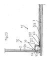
- a further embodiment of the tank construction according to the invention with a vacuum-tight gap as a monitoring chamber comprises an edge segment with a lying plate and a bottom segment with a bottom plate.
- the lying plate and the bottom plate are aligned parallel to the inside of the tank bottom.
- the lying plate is attached with its outer edge region against the tank shell and connected to this vacuum-tight, preferably vacuum-tight welded to form vacuum-tight welds; the inner edge region of the lying plate rests on the outer edge region of the base plate and likewise connected to it in a vacuum-tight manner, preferably welded vacuum-tight to form vacuum-tight weld seams.
- the outer edge region of the bottom plate which is held by a arranged between the bottom plate and the inside of the tank bottom layer with steel mesh fabric at a distance, is tacked to the tank bottom only to form stapled welds.
- under a layer of steel mesh fabric may also be a layer comprising a fabric with other materials, such as metallic materials, their alloys, e.g. Iron or steel alloys, plastic-like or mixtures thereof, understood.
- the intermediate space is essentially defined by the lying plate and the base plate and the corresponding areas of the tank cover and the tank bottom facing the lying plate and bottom plate.
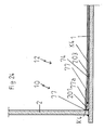
- An additional embodiment of the tank construction according to the invention with a vacuum-tight gap as a monitoring chamber comprises two deck plates as edge segment and two floor panels as floor segment, which are aligned parallel to the inside of the tank bottom.
- the bottom-side lying plate is held by the bottom-side bottom plate of the inside of the tank bottom at a distance, since a part of the bottom-side bottom plate, preferably its outer edge region, between the bottom-side lying plate and the tank bottom is located.
- the outer edge region of the bottom side lying plate is vacuum-tightly connected to the tank jacket, preferably vacuum-tight welded to form vacuum-tight welds.
- the inner edge region of the bottom-side lying plate is also connected vacuum-tight to the bottom-side bottom plate, preferably vacuum-tight welded to form vacuum-tight welds.
- a layer of steel mesh fabric is arranged between the bottom-side floor panel and the upper floor panel, so that the upper floor panel of the bottom side Floor panel is also spaced.
- the outer edge region of the upper floor panel is stitched to the base-side lying plate only to form stapled welds.
- the upper decking plate is kept at a distance from the bottom-side decking plate by the entry of the outer edge area of the upper floor panel between the upper decking plate and the floor-side decking plate.
- the outer edge region of the upper lying plate is vacuum-tightly connected to the tank jacket, preferably vacuum-tight welded to form vacuum-tight welds; the inner edge region of the upper decking plate is also connected in a vacuum-tight manner to the outer edge area of the upper floor panel, preferably vacuum-sealed to form vacuum-tight welds.
- the intermediate space is limited essentially by the upper lying plate, the upper floor plate, the bottom side lying plate and the bottom side floor plate.
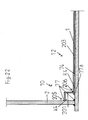
- the edge segment comprises a standing plate, a lying plate and the ground segment a floor panel.
- the standing plate is inclined in the direction of the tank bottom, so that its outer edge region has a greater distance from the inside of the tank bottom than its inner edge region.
- the outer edge region of the floorboard is attached against the tank shell and connected to this vacuum-tight, preferably vacuum-tight welded to form vacuum-tight welds; the inner edge region of the floorboard is attached against the outer edge region of the lying plate and connected vacuum-tight, preferably vacuum-tight welded to form vacuum-tight welds.
- the deck plate is inclined as the standing plate toward the tank bottom, the inclination of the deck is supported by a spacer which is disposed in the outer edge region of the deck between the deck and the tank shell.
- the lying plate is attached with its inner edge region against the inside of the tank bottom and hooked only to the tank shell to form stapled welds.
- the floor panel is spaced from the inside of the tank shell by a layer of steel mesh fabric disposed between the floor panel and the tank shell.
- the outer edge region of the floor panel rests on the inner edge region of the lying sheet and is connected to it in a vacuum-tight manner, preferably in a vacuum-tight manner to form vacuum-tight weld seams welded.
- the intermediate space is essentially limited by the standing plate, the lying plate and the bottom plate and the respective areas of the tank jacket and the tank bottom facing the standing plate, the lying plate and the bottom plate.
- the edge segment comprises two longitudinally L-shaped lying plates which are held at a distance from each other.
- the floor segment comprises two floor panels.
- the outer edge regions of the lying plates are attached against the tank shell and connected to the tank jacket vacuum-tight, preferably vacuum-tight welded to form vacuum-tight welds.
- the inner edge region of the lower lying plate is attached against the upper side of the bottom side bottom plate and connected to this vacuum-tight, preferably vacuum-tight welded to form vacuum-tight welds.
- the inner edge region of the upper decking plate is set against the top of the upper floor panel and connected to this vacuum-tight, preferably vacuum-sealed to form vacuum-tight welds.
- the inner edge region of the lower lying plate has a smaller distance to the tank shell than the inner edge region of the upper lying plate to the tank shell.
- the bottom-side bottom plate is located on the inside of the tank bottom, wherein the outer edge region of the bottom plate is stitched to the tank bottom to form stapled welding points.
- a layer is arranged with steel mesh fabric, so that the upper floor panel is spaced from the bottom side floor panel.
- the outer edge region of the upper floor panel is hooked to the bottom floor panel only to form stapled welds.
- the space is limited essentially by the two spaced lying plates and the two spaced floor plates.
- the tank construction according to the invention may comprise two vacuum-tight spaces as monitoring chambers, the edge segment comprising at least one lying plate and the ground segment at least one floor panel, the edge segment is vacuum-tightly connected to the ground segment, the edge segment or a part thereof a gap and the ground segment or a part thereof limit further gap, the edge segment is connected to the tank jacket vacuum-tight, at least one Lying plate and / or at least one standing plate at a distance from the inside of the tank shell and / or the inside of the tank bottom and the bottom plate are arranged at a distance from the inside of the tank bottom.
- the tank construction according to the invention can also have at least two intermediate spaces as vacuum-tight monitoring chambers.
- the edge segment comprises a standing plate and a lying plate and the ground segment only a floor panel.
- the standing plate and the lying plate are inclined towards the tank bottom, so that the outer edge regions of the standing plate and the lying plate have a greater distance from the tank bottom than the inner edge regions of the standing plate and the lying plate.
- the outer edge region of the floorboard is attached against the tank shell and connected vacuum-tight, preferably vacuum-tight welded to form vacuum-tight welds.
- the inner edge region of the floorboard with the outer edge region of the reclining plate and the inner edge region of the reclining plate are vacuum-tightly connected to the tank bottom, preferably vacuum-tight welded to form vacuum-tight welds.
- the inclination of the lying plate is supported by a spacer which is arranged in the outer edge region of the lying plate between the lying plate and the tank bottom and on which the lying plate rests.
- the bottom plate extends in substantially parallel to the inside of the tank bottom, wherein the outer edge region of the bottom plate rests on the inner edge region of the lying plate and vacuum-tightly connected, preferably vacuum-tight welded to form vacuum-tight welds is.
- the one gap is essentially defined by the standing plate and the lying plate and the respective standing plate and lying plate facing areas of the tank shell and the tank bottom.
- the second intermediate space is limited essentially by the floor panel and the area of the tank jacket facing the floor panel.
- a further embodiment of the tank construction according to the invention with two vacuum-tight spaces as vacuum-tight monitoring chambers comprises an edge segment with a standing plate and a lying plate and a bottom segment with two base plates.
- the standing plate and the lying plate are in turn inclined towards the tank bottom, wherein the outer edge region of the standing plate against the tank shell attached and connected to this vacuum-tight, preferably forming vacuum-tight Weld seams are welded vacuum-tight.
- the inner edge region of the floorboard is attached against the inner edge region of the lying plate and connected to this vacuum-tight, preferably vacuum-tight welded to form vacuum-tight welds.
- the inner edge region of the lying plate is attached against the tank bottom and also connected to this vacuum-tight, preferably vacuum-tight welded to form vacuum-tight welds or stitched together to form stapled welds.
- the bottom-side bottom plate runs substantially parallel to the inside of the tank bottom, wherein between the upper bottom plate and the bottom-side bottom plate, a layer is drawn with steel mesh fabric or is arranged, so that the upper bottom plate is held by the bottom-side bottom plate at a distance.
- the outer edge region of the upper floor panel and the bottom floor panel are spaced apart on the deck and are vacuum-tight, preferably vacuum-sealed to form vacuum-tight welds, wherein the outer edge region of the upper floor panel has a shorter distance to the tank shell than the outer edge region the bottom side floor panel.
- the one space is limited substantially by the standing plate and the lying plate and the respective the standing plate and the deck plate facing areas of the tank shell and the tank bottom; the second space is formed substantially from the two floor panels, which are spaced apart from each other.
- a further embodiment of the tank construction according to the invention with two vacuum-tight spaces as monitoring chambers comprises as edge segment a longitudinal section L-shaped lying plate and a bottom-side lying plate, and as floor segment two floor panels with an upper floor panel and a bottom floor panel.
- the L-shaped lying plate is attached with its outer edge region against the tank shell and connected to him vacuum-tight, preferably vacuum-tight welded to form vacuum-tight welds.
- the inner edge region of the L-shaped lying plate is attached against the tank bottom facing away from the top side bottom plate and also connected to this vacuum-tight, preferably vacuum-tight welded to form vacuum-tight welds.
- the bottom-side baffle which is spaced from the inside of the tank shell, is tacked only with its outer edge region with the tank shell to form stapled welds;
- the inner edge region of the bottom side lying plate is vacuum-tightly connected to the tank bottom, preferably vacuum-tight welded to form vacuum-tight welds.
- a layer of steel mesh fabric is retracted, so that both are spaced apart.
- the outer edge area of the upper floor panel and the outer edge area of the floor-side floor panel are vacuum-tightly welded to the upper side of the base-side lying panel, wherein the outer edge area of the upper floor panel has a shorter distance from the tank jacket than the outer edge area of the floor-side floor panel.
- the one space is substantially defined by the L-shaped deck plate and the bottom deck plate and the respective areas of the tank shell and the tank bottom facing the L-shaped deck plate and the bottom deck plate.
- the other space is limited by the two opposing floor panels.
- An additional embodiment of the tank construction according to the invention with two vacuum-tight gaps comprises an edge segment with a standing plate and two lying plates, and a bottom segment with three bottom plates.
- the bottom-side lying plate runs parallel to the inside of the tank bottom and rests on this.
- the outer edge region of the bottom side lying plate is connected to the tank shell and the inner edge region of the bottom side lying plate is vacuum-tight with the tank bottom, preferably vacuum-tight welded to form vacuum-tight welds.
- the standing plate and the upper deck plate spaced from the bottom deck are inclined towards the tank bottom, so that the outer edge portions of standing panel and deck plate have a greater distance from the tank shell than the inner edge portions of standing panel and deck plate.
- the outer edge region of the floorboard is set against the tank shell and the inner edge region of the floorboard is attached against the outer edge region of the recliner and this vacuum-tight connected in the region of the attachment points, preferably vacuum-tight welded to form vacuum-tight welds.
- On the inner edge region of the bottom-side lying plate is a bottom-side bottom plate, which runs parallel to the inside of the tank bottom.
- the outer edge region and the inner edge region of the base-side bottom plate are connected vacuum-tight to the base-side lying plate, preferably vacuum-tight welded to form vacuum-tight welds.
- the lower floor panel is partly on the bottom side Base plate, wherein its outer edge region with the bottom-side bottom plate vacuum-tightly connected, preferably vacuum-tight welded to form vacuum-tight welds, is.
- the upper floor panel lies with its outer edge area on the inner edge region of the upper deck plate.
- the outer edge region of the upper floor panel is connected in a vacuum-tight manner to the lying panel, preferably vacuum-tight welded to form vacuum-tight welds.
- a layer of steel mesh fabric is retracted, so that the upper floor panel is kept at a distance from the lower floor panel.
- the one space is limited by the standing plate, the bottom-side bunk and the bottom plate spaced lying plate and the area of the tank shell, which faces the standing plate and lying plate.
- the second space is bounded by the upper floor panel, the lower floor panel, and a part of the floor-side recessed sheet and a part of the floor-side floor panel.
- the edge segment comprises two floor panels, two lying panels and the floor segment three floor panels.
- the floor plates and the lying plates are inclined towards the tank bottom.
- the outer edge regions of the floor plates are attached to the tank shell and connected to this vacuum-tight to form vacuum-tight welds, preferably vacuum-tight welded to form vacuum-tight welds.
- the lower standing plate is attached with its inner edge region against the outer edge region of the lower deck plate and connected to this vacuum-tight, preferably vacuum-tight welded to form vacuum-tight welds.
- the upper upstand is also attached with its inner edge region against the outer edge region of the upper deck plate and connected to this vacuum-tight, preferably vacuum-tight welded to form vacuum-tight welds.
- the lower lying plate is attached with its inner edge region against the parallel to the inside of the tank bottom extending bottom-side bottom plate and also connected to this vacuum-tight, preferably vacuum-sealed to form vacuum-tight welds.
- the upper deck plate is attached with its inner edge region against the inner edge region of the lower deck plate and with this vacuum-tight, preferably vacuum-tight welded to form vacuum-tight welds.
- the lower lying plate has a lower inclination than the upper lying plate.
- the bottom-side bottom plate is located on the inside of the tank bottom, wherein the outer and inner edge regions of the bottom-side bottom plate are tacked to the tank bottom to form stapled welds.
- the lower floor panel is located with its outer edge region on the inner edge region of the bottom side floor panel and is vacuum-tight connected with its outer edge region with the bottom side floor panel, preferably vacuum-tight welded to form vacuum-tight welds.
- the upper floor panel lies with its outer edge region on the inner edge region of the upper deck plate and is vacuum-tightly connected to the decking plate, preferably vacuum-tight welded to form vacuum-tight welds.
- the upper floor panel is spaced from the lower floor panel and the bottom floor panel by a layer of steel mesh cloth disposed between upper floor panel and lower floor panel.
- the one space is bounded by the upper upright plate, the lower upright plate, the lower deck plate and the upper deck plate and a part of the area of the tank shell facing the upper upright plate.
- the second gap is essentially formed by the upper floor panel, the lower floor panel and a part of the bottom floor panel, as well as a part of the upper deck and lower deck.
- the invention is also based on the use of a bottom segment, preferably of two in plan view semicircular bottom segments.
- the floor segment may comprise an upper floor panel and a lower floor panel, which may form the double bottom of the floor segment and which from each other, for example by a between two floor panels arranged layer with steel mesh fabric may be spaced to form the gap as a monitoring chamber.
- the lower floor panel and the upper floor panel of the bottom segment limit or close off the monitoring chamber of the bottom segment in a vacuum-tight manner on the top and bottom sides.
- the lower floor panels are aligned with their lower floor panels and / or the upper floor panels with their upper floor panels in a plan view of a hollow cylindrical tank structure transverse to a central transverse axis Q thereof.
- the gap of the bottom segment may also be limited or sealed vacuum-tight; thus, the space of the ground segment may be laterally separated from means, e.g. of top and bottom shims in the region of the chamber separation, or of flat iron, vacuum-tight limited or vacuum-sealed, in the lateral region of the bottom segment, e.g. the region of the bottom segment facing the edge segment, the space of the bottom segment may also be limited or vacuum-tight, so that the space of the bottom segment laterally vacuum-tight limited or vacuum sealed, for example, parts of the edge segment. by the vacuum-tight welding of the upper floor panel, e.g.
- the lateral closure of the ground segment or its interspace may be provided e.g. by a transition of the edge segment to the floor segment, wherein the upper floor panel against a portion of the upper deck surface and the lower floor panel sheet against a portion of the lower deck sheet surface are able to lie and vacuum-sealed each other.
- the space of the ground segment can laterally pass into the space formed by the upper mud cup and the lower mud cup and / or the upper bottom sump tank and the lower bottom sump tank, so that these spaces one from two or more rooms, ie gaps , existing, eg for gas or liquid continuous, monitoring chamber can form and also the gap, the upper mud cup and lower mud cup and / or is formed by upper bottom sump container and lower bottom sump container, can be monitored by means of the leak detector connected to the monitoring chamber of the bottom segment or a vacuum monitoring device.
- the occurrence of leakage or leakage of, for example, formed by the sludge cups gap is due to the advantageous continuity or permeability of the gas or fluidly connected spaces of ground segment and mud cups to a gap immediately in a simple manner over a example in the region of the space Bodensegments attached leak detector recognizable.
- the permeability to gas Stapling, stapling or stapling can also be understood in the sense of the invention, the pointwise welding or the spot welding of parts with each other;
- the mutually joined or stiffened parts such as metal sheets, while held positional each other, but in particular the stapling and the stitched Versch pareungstelle no vacuum-tight connection of the components with each other, but can the patency of the gases and liquids between the welds or to the same allow.
- inclination in the sense of the invention also means a gradient which extends in the longitudinal section of the tank structure from the outside, eg from the outer edge region B, inwards, eg to an inner edge region BX of the tank bottom, wherein the distance of the outer edge region , eg the sheet, to the tank bottom is greater than the distance of the inner edge region, for example of the sheet, to the tank bottom;
- the inclination of the concrete layer can be such that the distance of the tank bottom facing away from the inside of the concrete layer of the tank bottom from outside to inside, for example, continuously or interrupted decreases.
- outer edge region B can also be understood as meaning the region of the tank container or the tank bottom facing the tank jacket.
- the inner edge region BX can also be understood as meaning the region between the edge region B and the center longitudinal axis of a hollow cylindrical tank container or the center of the circle of a circular tank bottom.
- the vacuum-tight welding of two parts to one another can be carried out by means of a TIG welding process with or without argon rinsing and / or by means of electrode welding.
- subsoil also means any surface for supporting the tank construction, for example, that of a ship, soil, or the like.
- vacuum-tight closure is also understood to mean the vacuum-tight or gas- or liquid-tight separation or the vacuum-tight or gas-tight or liquid-tight closure.
- vacuum-tight limitation is also understood to mean the vacuum-tight closure, vacuum-tight sealing or vacuum-tight closure to the outside and / or to the inside.
- vacuum-tight connection can also be understood as meaning the coupling with simultaneous vacuum-tight sealing or impermeable closure or lack of continuity for gases and liquids of the coupling point, eg the welding points or seams, wherein, for example, in the embodiment of the vacuum-tight connection of the bottom the edge segment of the space bounded by the edge segment or a part thereof and the space bounded by the bottom segment or a part thereof may be connected to one another in a gas- and liquid-like manner, however the interspaces are vacuum-tight, so that a monitoring chamber is formed from the two interspaces.
- the coupling with simultaneous vacuum-tight closure or vacuum-tight closure or lack of patency for gases and liquids of the coupling point with the limited by the edge segment or a part of the same space or gaps not with that of the ground segment or a portion of the same limited space or spaces may be connected to each other gas and liquid, but each space is vacuum-tight for itself, so that two monitoring chambers are formed.
- vacuum-tight sealing is also understood to mean the vacuum-tight closure, the sealing against gases and liquids or the impermeability to gases and liquids.
- the invention is also based on the laying of the floor panels in the form of floor panels, wherein in the field of so-called web separation, also called web separation area, or coupling of adjacent floor panels of a ground segment the side portions of the two adjacent upper floor panels of a floor segment are arranged overlapping each other, wherein a side portion of a first upper floor panel disposed on the upper-side shim iron is stitched with the upper-side shim, the side area of the second upper floor panel web arranged on this side area is welded to it in a vacuum-tight manner, so that the overlapping side portions of the floor panels on top Unterlegflacheisen, which eg are riveted to the bottom side with the arranged on the bottom of the tank GRP layer and / or the bottom of the tank riveted and stapled with these are arranged, the top side shims are stapled with the bottom shims, the side portions of the two adjacent bottom floor panels of this floor segment are arranged on the bottom-side lower flat iron and are
- the invention is also based on the laying of the floor panels in the form of floor panels, wherein in the area of the so-called chamber separation of two, eg in plan view semicircular, floor segments, also called chamber separation area, such as the provision of a vacuum-tight completion of the monitoring chamber of a ground segment of the monitoring chamber of the other ground segment, with the arranged on the tank bottom GRP layer and / or directly on the bottom of the tank riveted bottom-side shims are arranged in the middle of the upper side Unterlegflacheisen smaller dimensions, the top side shims with the bottom side shims are stapled with their one side and are vacuum-sealed with their other side opposite the one side, on a part of the bottom-side shim strips spaced from each other opposite lower floor panels of two floor segments are arranged with their inner edge regions, the inner edge regions of the lower floor panel webs, which are arranged on the bottom-side shim strips, are vacuum-tightly welded to the bottom-side shim
- the sheets of the edge segment comprise one or more lying plates, such as the lower lying plate, the lower standing plate, the upper standing plate and / or the upper decking;
- the panels of the floor segment may comprise one or more floor panels, such as the upper floor panel and / or the lower floor panel, so that the floor segment may comprise a wall or a double wall.
- the lower lying plate, the lower standing plate, the upper standing plate, the upper lying plate, the upper floor panel and the lower floor panel may be composed of one or more tracks, also referred to as segments or sheet metal, or be composed, these as lower decking, lower floor panels , upper sheet steel tracks and upper decking, upper floor panels and lower floor panels can be referred to.
- the metal sheets can each be created as a plate-shaped, for example, shock on impact, each other or partially overlaid with their edge or side areas.
- the segments or sheet metal webs may be made of a high quality material, such as stainless steel, and / or delivered in the form of rolls from the factory and laid out in sheet form on site.
- a flat iron or a flat iron also means a flat sheet, a plate or a plate-shaped flat piece, preferably with a matching wall thickness, with a metal and / or plastic-like material or material.
- sheets such as standing sheets, lying sheets, floor sheets, support sheets, and their sheets, such as sheet-metal sheets, cover sheets, floor sheets, sheet-metal sheets, are also understood to mean those which contain or consist of metallic materials and also those which contain plastic type or can consist of these.
- the flat iron can be connected to the back of the sheets, as welded, eg welded or stapled vacuum-tight.
- the sheets provided with the flat iron can be when assembling the sheets in series or in ring form each other with the Underlay flat iron, also called mutual undercut or with undergrip, so that, for example, a metal sheet with its flat iron engages beneath it.
- the sheets provided with the flat iron can serve as so-called weld pool, so that when laying the sheets on the tank bottom or when applying the same against the tank shell of the projecting part of the flat iron of a sheet can serve as a support for the adjacent sheet to be applied.
- this undercut of the flat iron stabilizes the compilation of the sheets when laid in series and the joint of the adjacent sheets. Due to the planar undercut, preferably backward flooding with eg argon, eg in the case of the TIG welding process, can be cost-reducing unnecessary.
- An additional object of the invention relates to a method of sealing a conventional tank construction, e.g. a flat-bottom tank construction, in particular a hollow-cylindrical tank construction, for liquids, in particular organic liquids, with a chamber monitoring arrangement, e.g.
- An additional object of the invention relates to the method of sealing a conventional tank construction, e.g. a flat-bottom tank construction comprising a layer applied on the tank bottom with a glass-fiber-reinforced plastic-like material, with the o.g. Process steps.
- the tank container and the tank bottom can be made with metallic materials such as iron, steel, etc .; the tank bottom may have an inner side with a metallic material or with a, eg glass fiber reinforced, plastic-like material; For example, on the inside, in addition, a layer applied to the metal tank bottom can be arranged with a, for example glass fiber reinforced, plastic-like material.
- the tank construction according to the invention may be suitable with a monitoring chamber comprising a top view in a circular ground segment and an annular top edge segment, which has a monitoring chamber together, the edge segment as the lower part lower lying and standing sheets and upper part as upper Lying and standing panels and the floor segment upper floor panels and lower floor panels may include, the lower and upper plates, the lower and upper floor panels and the upper floor panels and lower floor panels only a vacuum in the longitudinal section of the tank structure U-shaped monitoring chamber limit or close, the Floor segment and the edge segment can rest on the tank bottom, the upper floor panel is largely spaced from the lower floor panel by an arranged between the two layer with steel mesh fabric, facing the edge segment against the lower of the tank bottom In the area of the inside of the tank shell is applied and welded to this vacuum-tight and merges the edge segment in the bottom segment.
- the tank bottoms additionally have a layer on the top side with glass fiber reinforced material and on this layer the tank shell facing in the outer edge region of the tank bottom concrete layer
- the tank construction according to the invention can with a monitoring chamber are suitable, a circular in plan view ground segment and a in plan view comprises annular edge segment, which together have a longitudinal section of the tank construction U-shaped monitoring chamber, wherein the vacuum sealed with the edge segment ground segment on the tank bottom and the edge segment can rest on the concrete layer, the edge segment against the bottom of the tank bottom facing the inside the tank shell rests and is welded to this vacuum-tight and merges the edge segment in the ground segment.
- the tank construction according to the invention can be equipped with e.g. three monitoring chambers are particularly suitable, comprising two in plan view semicircular ground segments and an annular in plan view edge segment; e.g. can the o.g.
- the tank construction according to the invention with three monitoring chambers are suitable, the two in plan view semicircular ground segments and a in plan view may comprise annular edge segment; It is advantageous that the above-mentioned edge segment can vacuum-tightly enclose a monitoring chamber with the lower lying plate, the upper lying plate and the lower standing plate and the upper standing plate, each floor segment a monitoring chamber with its upper floor panel on the upper side and lower floor panel below and laterally the inner and outer edge areas its floor panels with facilities, For example, underlay flat, collar plates, with parts of the edge segments, etc., vacuum tight seal or limit, the upper floor panel is largely spaced from the lower floor panel of each floor segment by a layer between them arranged with steel mesh, the floor segments on the tank bottom and the edge segment on the concrete layer can rest, the edge segment abuts against the bottom of the tank bottom facing the inside
- an inventive tank construction with the annular edge segment and four quarter-circular floor segments with five monitoring chambers can be used.
- a tank construction according to the invention with an annular edge segment separated into a plurality of sections in a plan view can also be used with a plurality of monitoring chambers and four quarter-circular floor segments with more than five monitoring chambers.
- a plurality of bottom-side plate-shaped flat iron ring or annularly about a center longitudinal axis M of the tank running on the arranged on the tank bottom GRP layer, the flat iron or directly on the tank bottom are arranged and with the Riveted layer and / or the tank bottom, if necessary, in addition, if necessary, welded.
- annular concrete layer extending in plan view about the center longitudinal axis M between an inner edge region BX and an outer edge region B of the tank container to form the top of the concrete layer in the outer edge region thereof a throat are applied so that their upper side facing away from the tank bottom in the direction of the tank bottom or center of the circle is inclined towards the same.
- a two-layer arrangement with a fire blanket facing the tank bottom and a layer facing away from the tank bottom with an aluminum foil can be applied against the throat of the concrete layer and the region of the inside of the tank shell adjacent to the throat, so that they are longitudinally sectioned. is designed shaped.
- a similarly trained lower sheet steel web attached with underside flat iron as Sch spabadêt with undercut the flat iron for the lower in plan view annular standing plate against an adjacent lower sheet bar track abutment annularly around the center of the tank bottom to each other, eg against or on the lower deck plate or lower decking and against the tank shell attached or attached, and stapled at the joint and / or flat iron.
- the vacuum-tight welding in particular the TIG welding process, preferably without argon flushing, the adjacent lower decking webs, at their common joints, also called-seams, together and the adjacent lower floor panels at their joint joints, also called seams, together and the vacuum-tight welding , in particular welding by means of electrode, the inner center of the circle the bottom of the tank facing edge regions of the lower sheet-metal webs with the lower deck sheets and the outer edge of the same remote from the center of the tank bottom of the same with the tank shell close to each other.
- the tightness of the welds can be carried out with the aid of the method according to the invention for the reliable checking of leaks in weld seams.
- tank construction and method according to the invention can after the preparation of spacers, annular around the circle center of the tank bottom, against the lower deck slabs and tacking them to the lower deck slabs the same design upper deck slabs with bottom-mounted flat iron as Sch spabadfeld with mutual undercut the flat iron for the upper annular lying plate to form joints annularly around the circle center of the tank bottom against each other against the lower deck plate and spacers attached and the upper decking sheets are stapled at joints.
- the vacuum-tight welding in particular the TIG welding process, preferably without argon flushing, adjacent upper decking at their joints and seams with each other, adjacent upper panel sheets at their joints and seams together and as well as the vacuum-tight welding, in particular welding by means of electrode, the inner edge regions of upper panel sheets with the upper decking and the outer edge areas of the same with the tank shell also done.
- the tightness of the welds is carried out by means of the method according to the invention for the reliable checking of leaks in welds.
- the lower deck sheets with flat iron attached to the underside are used as weld pool protection laid with mutual undercut the flat iron for the lower annular plate on the bottom of the tank and stapled with this, which has no fiberglass layer.
- the vacuum-tight welding preferably without argon flushing, the side portions of transverse to the transverse axis Q transverse lower
- the transverse transverse to the center transverse axis Q extending bottom-side shim and the stapling of the upper side resting on the bottom shim flat floor flat iron to the bottom side shim iron join.
- applying or applying to components also means applying, applying, resting, applying or arranging, for example surface-to-surface, such as planar arrangement of the lower lying sheet on or against the inside of the tank bottom, or for example edge of the upper floorboard on surface, as in the region of the attachment point of the upper floor panel with the tank shell or the arrangement of the upper floor panel against the tank shell.
- surface-to-surface such as planar arrangement of the lower lying sheet on or against the inside of the tank bottom, or for example edge of the upper floorboard on surface, as in the region of the attachment point of the upper floor panel with the tank shell or the arrangement of the upper floor panel against the tank shell.
- the tank construction according to the invention with a chamber monitoring arrangement as a chamber monitoring system for liquids, in particular for organic liquids, e.g. Diesel fuels, with metallic materials comprises a, preferably hollow cylindrical, tank container with a supported against a solid ground tank bottom and a protruding from the tank bottom, preferably cylindrical tank shell.
- the tank construction according to the invention may contain not only metallic materials but also plastic-like or mixtures thereof;
- the chamber monitoring arrangement may contain metal materials, but also plastic-like or mixtures thereof.
- the chamber monitoring system comprises at least one intermediate chamber for monitoring the tightness of the tank construction with respect to liquids, wherein at least one intermediate chamber is formed by an edge segment and / or a floor segment.
- the edge segment and the bottom segment can together define at least one intermediate chamber in a vacuum-tight manner.
- the bottom segment closes at least a portion of the inside of the tank bottom and the edge segment at least a portion of the inside of the tank bottom and the lower portion of the inside of the tank shell tight, such as vacuum-tight from.
- the in the outer edge region of the tank bottom preferably in plan view around the circular center of the tank bottom circumferential annular edge segment abuts against the lower region of the tank bottom facing inside of the tank shell and is connected to this vacuum-tight, in particular welded.
- the edge segment of the tank construction according to the invention comprises the lower lying plate, the upper lying plate, the lower standing plate and the upper standing plate, which close or limit the longitudinally L-shaped intermediate space, here monitoring chamber, vacuum-tight.
- the edge segment defines at least a part of the inside of the tank bottom and the lower region of the inside of the tank shell vacuum-tight
- the bottom segment defines at least a part of the inside of the tank bottom vacuum-tight
- the space of the bottom segment is the bottom bordered by a lower floor panel and the upper side of an upper floor panel, which in the outer edge region of the tank bottom in plan view around the circle center KM of the tank bottom peripheral edge segment is set against the lower portion of the tank bottom facing inside of the tank shell and welded vacuum-tight with this and the gap of the edge segment is L-shaped in longitudinal section and the gap of the bottom segment of the gap of the edge segment vacuum-tight manner.
- the intermediate space of the edge segment prefferably be formed by a lower standing plate, the upper standing plate, the lower lying plate and the upper lying plate, and / or the space of the bottom segment to be laterally provided with one or more of mutually superposed sludge cups and / or bottom sump containers arranged one above the other formed intermediate spaces liquid and / or gas for the exchange of liquids and gases between the spaces is connected.
- the tank bottom comprises on the inside a layer with a glass fiber reinforced plastic-like material, so that the inside of the tank bottom both from the plan view of the tank bottom around the circle center KM of the tank bottom rotating, arranged on the layer, in longitudinal section in the direction of the center of the circle KM inclined concrete layer and from the side of the concrete layer (3) laterally limited part of the layer, which is not bounded on the upper side of the concrete layer is formed.
- the upper floor panel with the upper deck plate and the lower spaced from the upper floor panel floor panel with the lower deck plate or with a bottom, arranged under the lower deck plate lying plate or with a bottom plate connected to the bottom plate (203) be welded vacuum-tight
- the edge segment is welded vacuum-tight with the tank bottom facing the lower region of the inside of the tank shell.
- the lower area of the inside of the Tank mantle, which is bounded by the edge segment vacuum-tight, does not extend over the entire height of the tank shell, but only on the height above which monitoring is required.
- the lower deck plate is flat on the inside of the tank bottom, which faces the tank shell, on.
- the inside of the tank bottom can be coated with a layer of fiberglass-reinforced plastic-like material, so that it is necessary, a concrete layer from the outer edge region B of the tank bottom to the inner edge region BX of the tank bottom with descending, the tank bottom facing away Apply top to this layer.
- the top of the concrete layer is inclined towards the center of the circle of the tank bottom or the center longitudinal axis of the tank shell.
- the tank bottom in the context of the invention, the bottom of the tank structure supported against the ground with the layer with a, e.g.
- the inside of the tank bottom can also be formed by the surface facing away from the tank bottom or side of the concrete layer and the layer with glass fiber reinforced plastic-like material or only by the layer or layer of metal material.
- the lower lying plate lies flat in this embodiment.
- the connection of the lower deck plate of the edge segment is provided in this embodiment of the tank structure according to the invention by stitching the inner edge region of the lower deck plate arranged on the bottom of the tank bottom plate-shaped Unterlegflacheisen and the bottom side Unterlegflacheisen are firmly connected to the GRP layer and / or the tank bottom, preferably riveted.
- the L-shaped space of the edge segment extends inwardly at both ends pointed; the vacuum-tight closure of the intermediate space through the hermetic sealing of the sheets ensures the tightness of the tank structure in its outer edge area.
- the space of the edge segment is referred to as a chamber or monitoring chamber, wherein its tightness or tightness by means of conventional and leak detectors or vacuum monitoring devices according to the invention can be checked.
- the lower lying plate, the lower standing plate, the upper standing plate and the upper lying plate can be composed of plate-shaped tracks, plate-shaped sheet metal or plate-shaped segments, which are referred to as lower decking, lower floor panels, upper sheets and upper decking.
- the lower deck caddies, lower panel sheets, upper panel sheets and upper deck cushions are also referred to below as sheets, sheets or segments.
- a plate-shaped flat iron is welded, preferably stapled, such that a portion of the flat iron projects beyond the one side of the web by a predetermined amount.
- the flat iron can extend over the entire length of this side of the web.
- the purposes of the invention is under the handle of the flat iron and the preparation of the flat iron sheet metal web against the back of this adjacent other metal sheet understood in the assembly or joining the same.
- the purposes of the invention is meant by welding pool protection and covering the backs of the composite metal sheets by welded to the backs flat iron, so that, for example An Argonauerung in the vacuum-tight welding of the joints by TIG welding process, for example, in the rear area, can be unnecessary.
- the distance W3 which corresponds to the distance of the edge of the side region of an upper floor panel from the edge of the side area of the other adjacent upper floor panel in the overlapping area, be equal to or smaller than the distance W2, the distance between the outer edge region of the upper floorboard and the outer edge region of the lower floorboard corresponds.
- the distance A4, which corresponds to the distance of the opposite inner edge regions of the lower floor panels from each other in the chamber separation area be equal to or greater than the distance W2 or W1, the distance between the inner edge region of the upper deck plate and corresponds to the outer edge region of the upper floor panel.
- the distance A3, which corresponds to the distance of the opposite inner edge regions of the upper floor panel tracks from one another in the chamber separation area can be equal to or greater than the distance W2 or W1.
- the lower lying plate with its lower lying slabs can include in longitudinal section an angle ⁇ with the tank bottom or with the GRP layer of 10 to 25 °, preferably 25 0 ; the upper baffle can enclose an angle ⁇ with the lower baffle of 2 to 5 °, preferably 3.5 °; the upper standing plate may include an angle ⁇ with the tank jacket, preferably 3-10 0 , more preferably 2 to 5 0 include.
- the lower standing plate is placed against the lower baffle plate and against the tank shell and closes with the tank shell at an angle ⁇ , which may preferably be half the angle ⁇ or may be 2 to 5 °, preferably 3.0 °.
- the lower deck plate may include plate-shaped decking.
- a flat iron is welded to the back of each lower deck.
- the flat iron protrudes by a predetermined amount with a part on the flat iron side facing the lower deck sheet.
- the flat iron extends over the entire side of the lower deck.
- To provide the lower berth will be similar formed lower deck slabs flat on the inside of the tank bottom or flat on the inside of the concrete layer and arranged on the tank bottom of the concrete layer facing and / or adjacent to this, so-called bottom side, flat iron, so that the projecting over the side of the flat iron of aoutheasternerchbahn at least partially abuts against the back of the adjacent identically formed Montblechbahn.
- the floor segment comprises an upper floor panel and a lower floor panel which are spaced from each other by a layer of steel mesh fabric disposed therebetween.
- the floor segment defines the vacuum-tight space used as a monitoring chamber, upper side by its upper floor panel and lower side by its lower floor panel.
- the space of the bottom segment may be laterally sealed or sealed vacuum-tightly by means such as flat iron, by the edge segment and its sheets, such as by the lower deck plate, reinforcing plates, etc.
- the space of the bottom segment may extend laterally, for example into one or more intermediate spaces, for example of the two superimposed, spaced apart sludge cups, or of the two superimposed, spaced apart bottom sump containers, etc., can be formed.
- the chamber separation region of the tank construction according to the invention is also understood to mean that region which is located between two adjacent, e.g. in plan view semicircular, ground segments in the region of the central transverse axis Q of the tank bottom or the tank shell is located; the chamber separation area enables the vacuum-tight closure of the intermediate chambers of two adjacent floor segments from each other, without an exchange of gases and / or liquids between the two spaces takes place.
- web separation region of the ground segment is also understood to mean that region which may comprise the side regions of two adjacent bottom plate tracks of a bottom segment running parallel to each other and the side sections of two adjacent bottom plate tracks arranged above or above the lower floor plate tracks; wherein the side portions of the top floor panels may overlap each other in the overlapping area.
- a floor segment may comprise an upper floor panel with upper floor panel tracks, wherein the side areas of adjacent floor panel tracks overlap, and a lower floor panel with lower floor panel tracks, wherein the side areas of adjacent floor panel tracks overlap.
- the chamber separation area comprises bottom side and top side flat iron.
- the lower shim strips can rest on the tank bottom or on its inside and be riveted to the tank bottom.
- the lower shim strips can rest on a three-layer arrangement which is applied to the GRP layer arranged on the tank bottom; and riveted to the tank bottom.
- a flat iron may be welded to the back of a bottom-side shim iron, which may protrude with a part over the flat iron side facing the shim by a predetermined amount.
- the back of a bottom-side Unterlegflacheisens can be partially limited by the flat iron, eg in half.
- the flat iron can extend over the entire length of the Extending flat iron facing side of the bottom side shim.
- trained Unterlegflacheisen be laid in series along the central transverse axis of the circular tank bottom in mutual underhand grip with flat iron on the same, so that the projecting over the side part of the flat iron of a Medblechbahn against the back of the adjacent identically formed videblechbahn is at least partially abut.
- the back of a similar formed videblechbahn is partially, preferably half, welded to the flat iron, preferably stapled.
- the upper deck sheets, lower sheet steel tracks and upper panel sheets, underside Unterlegflacheisen and upper side Unterlegflacheisen can be formed and it can proceed or proceed with them.
- a flat iron is welded to the back side of a top side shim iron, which protrudes with a part over the flat iron facing side of the top side shim by a predetermined amount.
- the back side of a top-side shim may be partially bounded by the flat iron, e.g. in half.
- the flat iron can extend over the entire length of the flat iron facing side of the top side shim.
- Another or other similarly shaped top shim may be laid in line along the center transverse axis of the circular tank bottom in the mutual undercut with flat iron thereon, such that the side-projecting portion of the flat iron of the one shim against the back of the adjacent co-planar shim at least partially.
- the back side of the similarly formed shim strip is partially, preferably half, welded to the flat iron, preferably stitched.
- the top side shims may have a smaller width than the bottom shims, due to the central location of the top shim on the bottom shim, the top side shims may be on both sides Unterlegflacheisen bearing surfaces of the bottom side shims are provided on which the bottom floor panels preferably placed spaced from the upper side shim with their inner edge regions and vacuum-tight connected with their inner edge regions with the lower shim iron, preferably welded or welded, can be.
- the upper side shims are also vacuum-tight welded on one side with the bottom side shim and stapled on the other side only with the bottom side shim.
- On the lower floor panels each has a layer of steel mesh.
- On the two layers are upper floor panels on whose inner edge areas also rest on the top of the top side shim and are welded vacuum-tight with these.
- similarly shaped shims are laid in a plurality of spaced apart rows transverse to each other across the center transverse axis to provide the area of web separation.
- the laying of the bottom-side shim is done in such a way that the flat iron facing side of a similar trained Unterlegflacheisens abuts against the side of the other bottom-side shim iron joint to form the joint, which faces the flat iron of a Unterlegflacheisens.
- the adjoining sides of the shims are stapled together, preferably also with flat iron, in order to secure the position. After stapling, the sides can be vacuum-tight welded using a welding process according to the invention without argon flushing as a TIG welding process.
- the bottom-side shim strips are likewise provided on the upper side with identically designed upper-side shims which, however, have no back-welded flat iron.
- a connection between the top side and the bottom side flat iron is done only by stapling. Since the upper side Unterlegflacheisen have a smaller width than the bottom side shims, support surfaces are provided on both sides of the upper side shim iron, on which rest the side portions of the lower floor panels and with which the side portions of the lower floor panels can be welded vacuum-tight.
- vacuum-tight through-welding or welding is understood to mean that the weld seam is made vacuum-tight.
- At least one layer of steel mesh fabric is resting on the bottom floor panels.
- a further upper floor panel web adjacent to this upper floor panel web lies on this one floor panel panel such that the side area of the further upper floor panel panel overlaps the side area of one upper floor panel panel and forms the so-called overlap area.
- the side region or the edge of the side region of the further upper floor panel web is welded vacuum-tight to the side area of the upper floor panel web.
- the tank construction according to the invention can comprise a tank container with a tank bottom and a tank shell perpendicular to the tank bottom of these projecting in plan view or cylindrical tank shell disposed on the tank bottom, a layer with a glass fiber reinforced plastic-like material can be applied.
- a screed mortar can be used which can be highly resistant to abrasion, high impact and impact strength, good flexural and compressive strength, easy processing and very good smoothing behavior.
- a Sikaflor screed mortar KH is suitable as screed.
- a concrete screed with the strength class C20 / 25 according to DIN EN 206, a screed mortar CT-C25 / F4 according to DIN EN 13813.
- the concrete screed is based on cement according to DIN EN 197 and aggregates of 0 manufactured to 8mm or 0 to 4mm according to DIN 4226.
- the concrete layer can have a compressive strength of 25 N / mm 2 , a bending tensile strength of 4 N / mm 2 and / or a thermal conductivity R of about 1.6 W / (mk), and a building material class A1 non-combustible according to 4102, and grain size of 0 to 8mm or 0 to 4mm.
- the concrete layer is characterized, for example, by sufficient abrasion resistance, tensile strength and compressive strength.
- a mixture of aggregates and binders which may be aggregates, fine gravel, sand, chippings or stone meal. Suitable binders are cement, anhydride, magnesia, betumen and synthetic resin.
- the screed may be composed of cement, gypsum (screed gypsum), such as calcium sulfate, and other binders with various additives known to those skilled in the art.
- glass-fiber-reinforced plastic-like material is also understood as meaning a conventional composite material with a combination of a matrix of polymers and glass fibers acting as an amplifier.
- the glass materials used for fiber reinforcement are present, for example, as fibers, yarns or rovings (glass fiber strands), tile, fabric or mats.
- Polymeric matrix systems for the glass-fiber reinforced plastic-like material can usually be both thermosets and thermoplastics. Examples of suitable thermosets are epoxy resins, unsaturated polyester resins, phenol and furan resins. Suitable thermoplastics are suitable polyamides, polycarbonates, polyphenylene oxides, etc.
- the L-shaped two-layer arrangement preferably comprises a layer with a fire blanket and a layer of aluminum foil.
- the one side facing away from the tank jacket leg layer with aluminum of the two-layer arrangement is together with the one leg of the L-shaped fire blanket on the top of the throat of the concrete layer and the other leg of the situation with aluminum and the fire blanket are for example against the inside of Tank mantle on.
- the location with the fire blanket is preferably facing away from the tank bottom.
- a fire blanket so-called conventional high-temperature fire blankets can be used, which are harmless to health up to a temperature range of 700 ° C.
- the conventional fire blanket can conventional inorganic and / or organic substances as so-called Flame retardants that can make the fabric with which the fire blanket is made, flame retardant or flame retardant.
- the fabric of fire blankets may be provided, for example, with an oxygen-barrier, thin coating.
- the fabric can be made with glass fibers and coated with the conventional flame retardants.
- the conventional fire blanket for example, has a weight of 1,050 g / m 2 .
- the lower collar plate of the lower mud cup which limits the opening thereof, used as a support surface for the lower floor panel in its the lower mud cup area facing away.
- the upper collar plate of the upper mud cup which delimits the opening thereof, is or can be spaced therefrom by means of a layer of steel mesh fabric.
- the upper collar plate is welded to the lower collar plate, e.g. stapled.
- a layer of steel mesh is partially arranged.
- the upper floor panel is located on the layer of steel mesh fabric and on the upper collar plate spaced from the lower floor panel and is vacuum-tight welded to the upper collar plate.
- the space between the two mutually spaced sludge cups transitions into the space formed by the two spaced apart upper and lower floor panels and are both gaseous and fluidly connected so that leaks in the gap of the sludge cups as leakage in the spaced apart upper and bottom floor sheet formed gap can be measured.
- the same principle of interstice connection or transition is also realized essentially in the arrangement or connection of the floor segment with bottom sump containers.
- the lower bottom sump container is connected to a lower riveted to the tank bottom collar plate, which limits the lower bottom sump container opening.
- the lower floor panel rests on and is welded vacuum-tight with this, in particular the region of the lower floor panel, which faces the lower bottom sump container.
- the upper collar plate is stapled to the lower collar plate.
- Another layer of steel mesh fabric is arranged on the outer edge region of the lower collar plate on which the lower base plate rests.
- the upper floor panel extends toward the bottom sump containers and is spaced from the lower floor panel on the upper collar panel.
- the bottom sump containers facing edge region of the lower floor panel is vacuum-tight welded to the lower collar plate.
- the bottom sump container facing edge region of the upper floor panel is vacuum-tight welded to the upper collar plate.
- the space between the two spaced-apart bottom sump vessels passes into the space formed by the two spaced-apart upper and lower floor panels and are both gaseous and fluidly connected so that leakage of the space of the bottom sump tanks as leakage in the spaced from the upper and bottom floor sheet formed gap can be measured.
- the three-layer arrangement which coincides in terms of area with the bottom of the lower collar plate.
- the lower collar plate rests on the three-layer arrangement.
- the lower collar plate with the three-layer arrangement is riveted to the GRP layer and the bottom of the tank.
- a lower cup-shaped bottom sump container is provided for the provision of the bottom sump, at the upper edge of which a lower collar plate surrounding the edge is vacuum-tightly sealed into the tank bottom.
- the lower bottom sump container receives a spaced from its upper side to form a gap upper bottom sump container, at its upper edge edge side wiewie later- the lower collar plate welded vacuum-tight and on the top side around the edges surrounding upper collar plate can be welded vacuum-tight, which is spaced by a layer of steel meshes of the lower collar plate.
- the outer edge region of the upper collar plate can be vacuum-tight welded to the lower collar plate, wherein the outer edge region of the lower collar plate protrudes beyond the outer edge region of the upper collar plate protruding by a dimension. Between the lower collar plate and the upper collar plate a surrounding the bottom sump container layer with steel mesh is arranged flat.
- the lower floor panel rests on a portion of the lower collar plate and on the lower floor panel a layer with steel mesh is arranged flat.
- the upper floor panel is arranged on the upper collar plate and disposed on the lower collar plate layer with steel mesh so that the upper floor panel rests with its inner edge region on the upper collar plate in the region of the lower bottom sump container and is welded vacuum-tight with this;
- a three-layer arrangement with an upper layer and a lower layer with aluminum foil and a middle layer between both arranged with a steel mesh fabric under the lower collar plate on the layer with glass fiber reinforced plastic-like material, wherein the lower collar plate with the layer and the tank bottom riveted is.
- TIG welding process the arc is drawn between a non-consumable tungsten electrode and the workpiece, and around the tungsten electrode may be disposed an annular nozzle from which argon purging flows argon onto the workpiece. The argon flow displaces the atmospheric air so that it can be welded under a neutral protective layer.
- the area of the tank bottom as a support for floating roof feet of the floating ceiling on two centrally superimposed spaced support plates, between which a layer of steel mesh surface can be arranged on surface the upper support plate is less in area than that lower and on the upper floor panel facing edge region of the upper support plate, the upper floor panel surface rests surface and is welded vacuum-tight with the upper support plate, preferably TIG welding without addition.
- the edge region of the upper support plate facing the upper base plate can be stapled to the lower support plate riveted to the bottom of the tank, preferably a conventional welding process by means of an electrode.
- the upper support plate has a smaller area than the lower support plate marginal bearing surfaces of the lower support plate can be provided on which the lower floor panel can be placed and vacuum-sealed ver or welded to the lower support plate, preferably by means of TIG welding process without addition.
- the lower floor panel is spaced from the upper floor panel, preferably due to the layer of steel mesh fabric disposed on the lower floor panel.
- the vacuum-tight space between the two spaced apart shelves may transition into the space formed by the two spaced apart upper and lower floor panels and may both be gated such that leaks in the spacing of the shelf panels as leakage in the spaced apart space Upper and lower floor plate formed gap can be measured.
- Under gaseous compound is understood in the context of the invention, the liquid compound.
- the lower support plate rests on the three-layer arrangement, which is arranged on the GRP layer is.
- the lower support plate is riveted to the three-layer arrangement, the GRP layer and the tank bottom.
- the further embodiment corresponds to the above-mentioned embodiment without GRP layer.
- the area of the tank bottom, which is provided as a support for the floating roof feet, may have a structure which can largely match the embodiment of the tank construction according to the invention for the provision of bottom sumps.
- the invention also relates to the arrangement and the mounting of nozzles for testing, suction, measurement, filling, etc., for example, from a gap to be checked of the edge segment and / or the ground segment.
- the tank shell has an opening for receiving a reinforcing tube, through which reinforcing tube, a pipe, for example, the nozzle, can be passed.
- the invention also relates to the arrangement and the mounting of nozzles for testing, suction, measurement, filling, etc., for example, from a gap to be checked of the edge segment and / or the ground segment.
- the tank shell has an opening for receiving a reinforcing tube, through which reinforcing tube a tube, for example, the nozzle, is passed.
- the breakthrough limiting areas of the tank shell take the reinforcing tube and are welded vacuum-tight with the reinforcing tube.
- the areas defining the two openings of the reinforcing tube are welded to the tube in a vacuum-tight manner. From the upper deck plate of the edge segment, an opening can be milled out, against the breakthrough limiting area a reinforcing ring is recognized, the opening has a larger diameter than the breakthrough of the decking.
- a breakthrough for receiving a reinforcing tube and from the upper deck a breakthrough be milled out over the pipe the reinforcing tube and welded pointwise welded to the tank shell, preferably stapled, a reinforcing ring is passed over the pipe and against the the pipe adjacent area of the upper deck plate is welded and welded to form vacuum-tight welds, wherein the tube is set against the breakthrough limiting portion of the upper deck plate, the tube with the reinforcing ring vacuum-tight is welded, as well as the vacuum tightness of welds as well as the space formed by the upper upright, the upper deck, the lower deck and the lower riser sheet chamber is checked by connecting the pipe to means for measuring, aspirating and filling the chamber leak detector.
- a breakthrough in the upper deck plate can be provided.
- a reinforcing ring is attached against the area of the lying plate, which limits the opening laterally. Its opening is aligned with the opening.
- the opening of the reinforcing ring has a larger diameter than the opening of the upper deck plate, so that a part of the area of the upper deckle which limits the breakthrough protrudes as a collar against which a pipe can be attached.
- the tube is welded to the reinforcing ring vacuum-tight with its one end. The other end of the tube is led out through an opening provided in the tank shell, for example by milling.
- the area of the tank jacket, which limits the breakthrough laterally, is welded to the outside of the reinforcing tube, which is centrally received by the opening, circumferentially vacuum-tight.
- a vacuum may be applied in the gap through the tube to check for leaktightness of the gap as chamber 1 of the rim segment.
- pipes can be connected to the chambers 2 and 3 of the floor segments by the same procedure over openings of the upper floor panels for the purpose of checking for tightness of the gap.
- the production of the web separation of a bottom segment in the web separation area is described separately from the production of the chamber separation area, the production of the edge segment, the bottom sump, the pipe connection to floor panels and the sludge cups, etc., but can readily the A method for producing the web separation region with that for producing the chamber separation region, the production of the edge segment, the production of the bottom sump container and / or the production of the sludge cups, etc., combined and performed, for example, at the same time.
- step a. for applying the flat iron on the tank bottom on this step a. be waived so that in step b. the laying of identically designed lower deck cushions with underside adhered projecting flat iron as Sch dibadêt with undercut the flat iron on the tank bottom and the stapling of this with the same and other steps, as stated above, can connect.
- the flat iron, the metal sheets, such as the lower deck sheets and the lower sheet bars are aligned radially around the center of the tank bottom or the center longitudinal axis of the tank shell.
- the flat iron, the metal sheets, such as the lower deck sheets and the lower sheet steel tracks aligned transversely to the center-transverse axis.
- the safe position of the sheets and dimensional stability of the chamber monitoring arrangement according to the invention and the tank construction according to the invention are advantageously supported by the attached to the undersides flat iron, since a metal sheet with its protruding part each positively engages under the adjacent sheet metal, so that two adjacent metal sheets on a flat iron support themselves and arranged by shock to shock arranged on the flat iron joint per two adjacent metal sheets can be welded vacuum-tight.
- the flat iron, the metal sheets, such as the upper decking and the upper sheet steel tracks are aligned radially around the center of the tank bottom or the center longitudinal axis of the tank shell.
- the flat iron, the metal sheets, such as the lower decking sheets and the lower sheet steel panels aligned transversely to the center transverse axis.
- the safe position of the sheets and dimensional stability of the chamber monitoring arrangement and the tank construction according to the invention are advantageously supported by the attached to the undersides flat iron, since a metal sheet with its protruding part each positively engages under the adjacent sheet metal, so that two adjacent metal sheets on the flat iron support themselves and the designed by impact against shock on the flat iron arranged joint per two adjacent metal sheets can be welded vacuum-tight.
- the formation of web separation of a bottom segment in the web separation region is described for clarity, separate from the methods of making the chamber separation region, bottom sumps, mud pockets, support sheets, and edge segment, etc., however, the methods of forming the web separation region may be the same for producing the chamber separation region, which are combined for producing bottom sump containers, for producing the sludge pockets, for producing the support plates and for producing the edge segment, and preferably at the same time.
- a reinforcing plate with breakthrough can be set against the bottom of the breakthrough limiting area of the bottom plate and is by means of a layer of steel mesh fabric of a flat iron, which is riveted to the tank bottom or with a tank bottom arranged on the GRP layer, spaced and can with his the edge of the tube facing away from the tube welded to the flat iron, as stapled be.
- the lower floor panel may rest on the edge area of the flat iron facing away from the opening and may be welded thereto, preferably in a vacuum-tight manner, preferably by means of a TIG welding method without addition.
- TIG welding without addition can also be understood as meaning the TIG welding process without argon purging.
- Another layer of steel mesh may be placed on the lower floor panel and on the portion of the flat iron between the peripheral area thereof and the aperture facing area thereof.
- the upper floor panel which is above the lower floor panel and above the portion of the flat iron between the edge region of the same and the breakthrough region thereof is arranged spaced apart due to the layer with steel mesh fabric and extends to the edge facing away from the breakthrough of the reinforcing plate and rests on this, can be vacuum-tight, with the edge region facing away from the breakthrough of the reinforcing plate, preferably by means of TIG welding process, be welded.
- a reinforcing ring may be passed over the tube and secured against the breach of the reinforcing plate defining portion thereof and welded to the reinforcing plate and tube by means of preferably TIG welding to form vacuum-tight welds.
- a gap is formed by flat iron, reinforcing plate and the two spaced apart lower and upper floor panels, which may also be liquid and gas connected to the interior of the tube.
- the intermediate space may be connected to the liquid and gas of the ground segment.
- the leak test includes the overpressure test and the two-edge edge test.
- the first test eg overpressure 0.3 bar
- the second test eg test pressure 0.8 bar
- very small defects such as hairline cracks, binding defects, etc.
- test equipment Liquid soap used, which is sprayed using a hand pressure sprayer replaced.
- a pressure recorder and a weather recorder are connected to the edge segment for a period of 24 hours.
- the bottom seams of the bottom and top bottoms are tested with water and a vacuum bell (eg test pressure minus 0.8 to 1.0 bar) and a slight argon overpressure is generated during the total test duration under the soil segment to be tested. Therefore, it is ensured that an unwanted coverage of weld defects is excluded by the foam.
- a vacuum bell eg test pressure minus 0.8 to 1.0 bar
- a liquid contained in a spray container containing a liquid soap in an aqueous solution is sprayed onto a predetermined area of a weld to be tested by means of a hand-operated pump, a vacuum hood is attached against the predetermined surface of a vacuum-tight sealing seam Is evacuated interior of the vacuum hood, in particular in the vacuum hood, a vacuum, preferably from -0.8 to - 1.0 bar, is generated, which vacuum hood is formed with a coupled to a frame disc with at least two valve-controlled openings, the space with argon subjected to a test pressure of 0.3 to 0.8 bar and tested the surface to be tested for blistering in the sprayed on liquid soap.
- a liquid is sprayed from a spray container onto the weld seam.
- the liquid is sprayed from the spray container with a hand-operated pump onto the predetermined surface to be checked.
- the liquid comprises a proportion of conventional liquid soap in an aqueous solution.
- the liquid soap in the aqueous solution for example, potassium soaps having a fatty acid content of 15 to 20%, e.g. Coconut fatty acids and / or oleic acid.
- the liquid soap is characterized in particular by a non-flammability, high environmental compatibility, sufficient biodegradability and solvent-free from the presence of fluorinated chlorinated hydrocarbons, etc.
- the chambers of the edge segment or of the floor segments are subjected to an overpressure on the predetermined surface sprayed or wetted with the liquid, so that in the case of leakage bubbles occur in the sprayed-on liquid solution in the area of the weld seam.
- a vacuum hood is attached on the predetermined surface of the weld sprayed or wetted with the liquid.
- the vacuum hood comprises a circumferential frame with a conventional pressure and vacuum-tight transparent to the frame vacuum-tight connected Slice with glass or plastic.
- On the frame openings are milled to which valves are connected.
- the interior of the vacuum hood can be controlled evacuated or vented or filled with liquid.
- the vacuum hood can be attached and evacuated via a valve against the predetermined surface to be controlled of the weld. Via another valve, a liquid is transferred into the interior of the vacuum hood without provision of the pressure compensation for checking for formation of bubbles in the liquid.
- interspaces here intermediate chamber 1 of the edge segment, and intermediate chambers 2 and 3 of the two floor segments can serve as interstices for checking the gas and liquid tightness of the tank construction.
- conventional leak detectors working on the negative pressure principle can be used above o.g. Stutzrohre be connected.
- vacuum leak detectors are connected as leak detectors, which can generate a negative pressure of, for example, 250 mbar in the interstitial space.
- the tank construction according to the invention and the method according to the invention for providing the tightness of tank tanks which are leaky in conventional tanks are characterized in that by the application of edge segment and the two adjacent semi-circular bottom segments neither the bottom of the tank nor the layer applied to the bottom of the tank are damaged with glass-fiber reinforced plastic-like material; There is also no risk of heating of tank bottom and layer.
- the tank construction according to the invention and the inventive method are characterized by a tension-free filing and a reliable welding of the parts of the floor segments and the edge segments with the tank shell.
- the tank construction according to the invention and the method according to the invention also prove advantageous, because additional attachments on the outer tank jacket are superfluous when attaching test, suction and measuring stubs.
- the chamber monitoring arrangement tank system according to the invention and the inventive method for tank structures the metal materials, such as iron or steel alloys, non-metallic materials such as plastic-like, or mixtures thereof contain or are produced with such.
- the chamber monitoring arrangement according to the invention and the tank construction according to the invention are characterized by high stability, so that the installation of the chamber monitoring arrangement according to the invention in the conventional tank construction does not affect the stability of the tank shell and thus of the tank construction.
- the force applied to the tank shell by, for example, the support to the tank bottom can be reduced such that after installation of the chamber monitoring arrangement cracks and gaps neither in the tank shell, in the transition region from tank shell to tank bottom still in the tank bottom does not occur.
- welds can be performed using the TIG welding process without argon purge.
- the method according to the invention for the reliable checking of weld seam leaks avoids the pressurization and skimming of the chamber of the edge segment with a conventional leak detection spray as foam.
- the sprayed on the site to be checked foam of the leak-seeking spray is blown away by awkwardness of the user.
- the method according to the invention also takes into account the prohibition of the use of the blowing agent CFC and the use of a leak detection foam pressurized in a spray container in a closed space by use of a hand spray device comprising a pump which can be manually operated.
- the predetermined area is checked and avoided by unwieldiness of the user unwanted coverage of weld defects.
- the inventive method is characterized by the repair of both tank bottoms tank farms without and with a layer of glass fiber reinforced plastic-like materials.
- the floor panels can be supplied rolled up in the form of rolls, spent in the tank building and easily laid in this, especially as the thickness D 1 of the lower floor or floor sheet, the upper floor or floor sheet correspond to 3 times the thickness D2 of a lower or upper floor sheet can.
- the method according to the invention avoids the costly and harmful removal of the layer with glass fiber reinforced plastic-like materials.
- the advantages of the method according to the invention are moreover the whereabouts of the layer with the glass-fiber-reinforced plastic-like material in the tank construction, Avoiding the costs of removal and disposal of the same, Avoidance of sandblasting of the tank bottom, Avoid checking for tightness of the tank bottom, avoiding repairs and inspections of the tank bottom, Avoiding the provision of mounting openings in the tank jacket wall for the purpose of introducing large floor panels, Avoiding a new coating on the top of the double floor to be inserted by using stainless steel double bottom and Avoidance of health impairment and fire hazard.
- the edge segment comprises the lower part, which has the lower lying plate and the lower standing plate, and the upper part, which has the upper lying plate and the upper standing plate.
- prefabricated flat iron with rivets preferably stainless steel rivets, in the inner edge region BX of the tank container and the tank bottom can be riveted circumferentially on the layer of glass fiber reinforced plastic-like material at a predetermined distance from the tank shell.
- the layer of fiberglass-reinforced plastic-like materials may be inclined in the edge region, so that the upper side of the layer rises from the inner edge region BX of the tank towards the outer edge B or to the tank jacket, it is advantageous to Apply a concrete layer in this area on the top of the GRP layer, which is formed in longitudinal section as a concrete wedge.
- the concrete layer serves as a support for the lower lying sheet.
- the concrete layer is arranged circumferentially around the center longitudinal axis M of the hollow cylindrical tank shell or the circular center of the arcuate tank bottom and extends annularly in plan view.
- the cast against the tank shell and the tank bottom concrete layer contains a conventional composition.
- the lower lying plate, the lower standing plate, the upper standing plate and the upper lying plate are composed of webs or segments respectively, which are referred to as lower deck sheets, lower sheets, upper sheets and upper deck sheets.
- the adjacent webs of a sheet such as a floorboard or a lying sheet, abut each other with the edges of their adjacent sides abutting, the one web can at least partially engage under the adjacent with a welded plate-shaped flat iron on its back.
- the prefabricated deck plates can be designed as a lower decking on the concrete layer surface on surface, for example, each adjacent two identically formed lower decking with their adjacent sides or edges abutting each other shock to form a joint on the on the side of the a lower slab track addition excellent part of the flat iron adjacent other identically formed lower deck slideway rests at least partially and welded in the region of the joint, the other slalom with a slug to the flat iron of a slab track pointwise, preferably stapled can.
- the stitching is advantageously carried out only after the completion of the laying or laying out of all required lower decking.
- Prefabricated floor sheets are applied as lower sheet steel tracks against the tank shell and against the lower decking sheets forming an angle ⁇ with the tank shell, with two identically formed adjacent lower single-sheet sheets abut with their adjacent sides or edges edge to edge to form a joint, on the on the side of a lower sheet-metal trajectory outstanding part of the plate-shaped flat iron, the adjacent other identically formed lower sheet steel plate at least partially rest and welded in the region of the joint, the other lower sheet bar to the one sheet steel or to the flat bar of a lower web plate pointwise, preferably stapled, can be.
- the lower sheet steel tracks with the lower decking sheets can be spot welded together, preferably stapled. The stitching is advantageously carried out only after the laying of all required lower sheets sheets.
- each of the adjoining in the region of the joints sides or edges of the lower decking sheets with the formation of butt welds preferably by means of a TIG welding process, vacuum-tight welded, without argon flushing is required, and each adjacent sides or their Edges of the lower sheet-metal webs to form butt welds, preferably by means of a TIG welding process, welded vacuum-tight, without argon purge is required.
- TIG welding process is understood in the context of the invention, a tungsten inert gas welding.
- the welding of the outer edge regions, also referred to as attachment points, of the lower sheet-metal webs with the tank shell, in particular by means of the electrode welding process can be carried out without argon purge being required.
- the area, also referred to as attachment point, on which the lower sheet steel tracks against the lower lying sheets are attached and stapled together are welded vacuum-tight to form a weld or joint seam, preferably by a welding process with electrode.
- the welds are cleaned, especially brushed, and prepared for leak testing.
- the lower decking of the lower part of the edge segment is stapled to spacers.
- the assembly and welding is carried out in the above procedure already carried out as in the assembly of the lower deck plate and the lower floor plate of the lower part of the edge segment, wherein the vacuum-tight weld or seam between the inner edge region of the upper floor plate is provided with the upper deck ,
- the prefabricated deck plates can be used as the upper deck berths against the lower deck berths and the spacers, each adjacent two identically formed upper deck berths abut each other with their adjacent sides and their edges abutting each other to form a joint on the side of the an upper deck slab track outstanding part of the plate-shaped flat iron, the adjacent other upper deck sheet at least partially rest and the other upper deck sheet welded to the flat iron of a top deck sheet pointwise, preferably stapled, can be.
- the upper decking sheets can be welded together pointwise with the lower decking sheets, preferably stapled. The stitching is advantageously carried out only after the laying of all required lower sheets sheets.
- Prefabricated floor panels are recognized as upper sheet steel tracks against the tank shell and against the upper decking to form an angle ⁇ with the tank shell as a starting point, with two adjacent identically formed upper sheets plates with their adjacent sides and their edges abutment to form a joint abut, on the side of the one upper sheet steel web addition outstanding part of the plate-shaped flat iron, the adjacent other upper Stand-up sheet web at least partially rest and the other upper panel sheet welded to the flat iron of a top sheet bar pointwise, preferably stapled, can be.
- the upper sheets of sheet metal with the upper decking sheets are spot welded together, preferably stapled.
- the welding of the outer edge regions of the upper sheets of sheet metal with the tank shell by means of the electrode welding process can be carried out without argon purge is required.
- the area at which the upper sheet steel webs attached to the upper decking sheets and welded pointwise, preferably stapled, are vacuum-sealed to form a weld or seam or butt weld, preferably by welding with electrode. Then the welds are cleaned, especially brushed, and prepared for leak testing and leak tested.
- the intermediate chamber 1 of the edge segment is provided as a check chamber whose tightness can be checked by means of the measuring, suction and educastutzens.
- the positions of the measuring, suction and test sockets e.g. this chamber is determined.
- a breakthrough through the tank shell for the pipe also called nozzle tube milled.
- the prefabricated suction, measuring and test stub for this chamber can be welded pointwise with the area bounding the opening of the tank shell, preferably stapled, preferably by means of TIG welding process.
- a breakthrough from the upper deck plate is milled out and the lower end of the spigot tube can be vacuum-sealed to the area of the breakthrough upper deck plate, preferably by TIG welding without argon purge.
- a reinforcing ring can be pushed and set over the nozzle tube, which can be welded to both the upper plate and the nozzle tube, preferably by means of TIG welding process without argon flushing.
- the welds are cleaned, brushed and tested.
- the measuring, suction and educastutzen be sealed with a blind cover and connected to the nozzle pipe a conventional operating on the negative pressure principle leak detector, preferably a vacuum pen with additional weather recorder, and a vacuum pump for generating - 600mbar.
- the prefabricated suction, metering and test port may be formed as a tube with a stainless steel material having a tube wall thickness of 1 "to prevent stapling of the stainless steel tube to the tank shell, and prior to optionally bending the tube, the reinforcing sleeve is placed on the stainless steel tube pushed and the reinforcing sleeve with the tube welded (using the TIG welding process).
- the two bottom sump containers which are spaced apart from one another, can be welded, cleaned and tested on collar plates, preferably by means of TIG welding methods. Subsequently, the lower collar plate, on the underside of which the upper edge of the lower bottom sump container and its upper bottom sump container facing edge of the upper edge of the upper bottom sump container are welded, provided on the underside with the three-layer arrangement and riveted to the tank bottom and the layer.
- the Layer arrangement comprises as upper layer an aluminum foil, a middle layer with steel mesh fabric and a lower layer with aluminum foil.
- This three-layer arrangement serves to space the lower collar plate from the layer with the glass-fiber reinforced plastic-like material and protects against the action of heat generated by subsequent welding operations in order to exclude fire and health hazards due to the formation of the welding gases.
- the upper edge of the upper bottom sump container preferably by means of TIG welding process, welded.
- a layer of galvanized steel mesh fabric can be arranged and fixed with adhesive tape.
- the lower bottom sump container with the lower collar plate embedded in the tank bottom can accommodate the upper bottom sump container.
- the edges of the lower and upper collar plates facing away from the bottom sump containers can be welded to one another by means of a TIG welding process, preferably point-wise.
- the installation of the supports for the floating roof feet is carried out with two hydraulic presses. Each floating roof foot is pushed up in the direction of the floating roof and the support plates for the floating roof feet with the upper and lower floor panel according to the arrangement of the bottom sump mounted on the layer of fiberglass reinforced plastic-like material.
- the mounting of the reinforcing plates of the suction, test and test sockets of the intermediate chambers of the floor segments can be carried out identically according to the installation of the bottom sumps and supports (see below).
- a plate-shaped flat iron can be spot welded, preferably tacked, to the bottom or bottom of each bottom flattened iron facing the tank bottom, which can be used to separate the webs and / or to couple the floor panels of a floor segment, so that one part of the flat iron protrudes over the side of the bottom-side shim and the projecting part is used for the flat support of an adjacent shim when laying the same in series and joint to shock.
- Sch can also at the tank bottom facing back or bottom of each bottom-side shim for the chamber separation of two floor segments and / or for coupling the inner edge regions of two floor segments a plate-shaped flat iron welded pointwise, preferably pinned, wherein a portion of the flat iron protrudes beyond the side of a bottom-side Unterlegflacheisens and the protruding part serves to support an adjacent Unterlegflacheisens.
- the chamber separation with a three-layer arrangement which an outer layer with aluminum foil, an inner layer with Steel mesh fabric and an outer layer with aluminum foil comprises, are laid as a substructure butt on impact on the fiberglass layer, so that the projecting part of the flat iron of a Unterlegflachesisens the adjacent Unterlegflacheisen under cover and the adjacent Unterlegflacheisen is able to lie flat at least partially or fully on this.
- the shims can be riveted with the arranged under the shim three-layer arrangement, the GRP layer and the tank bottom and adapted to the lower part of the edge segment, shortened if necessary, and welded to the lower deck sheets.
- a plurality of parallel rows of in-line shims also called sheets or bottom shims, can be separated 90 ° from the shims for sheave separation on the three-layer arrangement resting on the glass fiber reinforced plastic-like material layer;
- a substructure in the direction of the axis 90 ° and 270 ° be installed butt joint, so that the flat bar engage under the adjacent Unterlegflacheisen and lie flat against this.
- the shim strips can be riveted to the three-layer arrangement, the GRP layer and the bottom of the tank, adapted to the lower part of the edge segment, possibly shortened, and / or welded to the lower lying slideways.
- the shims Upon collision of the shims with the bottom sump, the supports for the floating roof feet and the reinforcing plates of the suction, measuring and test tubes of the chambers 2 and 3, the shims are adapted, and welded to the corresponding component of the lower floor. Subsequently, all joints, seams and welds the chamber separation and web separation welded, preferably welded by means of TIG welding process without argon flushing and brushed. The testing of the welds takes place only in connection with the complete underbody test.
- the prefabricated in the workshop bottom floor panels can be rolled out on the bottom side shims of the web separation.
- holes are cut so that an overlap on the support plates can be done.
- an opening is cut.
- the connection is made by cutting a hole, so that an overlap can take place.
- the bottom plate overlaps on the web separation and on the lower edge segment in a predetermined manner.
- Each bottom floor panel may now be circumferentially spot welded, preferably stapled with a TIG special point gun, e.g. with dot spacing of 10 to 15 mm, without welding filler dotted or stapled.
- the entire subfloor is TIG-welded by the lower floor panels are vacuum-tight welded or welded through to the bottom-side shim, preferably by means of a TIG welding process without argon flushing both at chamber separation and web separation. Now all welds are cleaned, brushed and prepared for leak testing.
- the assembly can begin chamber separation and web separation of the upper floor panel.
- a plate-shaped flat iron can be attached to the back of each flattening iron to protect it from sweat.
- a flat iron welded pointwise, preferably pinned, so that a part of the flat iron on the side of the upper side Unterlegflacheisens order protrudes a measure and the projecting part for the surface support of an adjacent top-side Unterlegflacheisens when laying the same in series and is used butting.
- both the top side flattening of the chamber separation with Sch josbadtechnisch and the top side Unterlegflacheisen the web separation can be stapled in the middle on the respective bottom flats and on the upper part of the edge segment, or on flat bar of the edge segment and the components of the upper floor (bottom sump, support for floating roof feet, Reinforcing plates of the suction, measuring and test tubes chamber 2 and 3) are adapted; the top side shims of the chamber separation can only be on the one e.g. the chamber 2 facing side with the bottom-side shim iron vacuum-sealed, such as completely welded through, however, the other side facing away from the chamber 2 of the top side shim can be spot welded to the bottom shim flat iron, preferably stapled, be.
- the separation of the two chambers is made; the top side shims of the web separation remain stapled only with the bottom side shims.
- the prefabricated metal sheets of the upper floor panel can be designed according to the following procedure.
- a layer of galvanized steel mesh from a roll unrolled, cut and fixed with adhesive tape on the first lower floor panel web.
- a first trimmed top floor panel may be rolled on top of this layer and top deck floor iron such that a portion of top deck floor iron may be overlapped by the first top floor panel panel;
- holes can also be cut in the layer and in the upper floor panel web on the support plates of the floating roof feet so that an overlap can take place via the support plates.
- the reinforcement plates of the suction, measuring and test tubes become an opening cut with overlap.
- the connection is made by cutting a hole, so that an overlap can take place.
- the first top floor panel web can be circumferentially welded, preferably stapled, to the top bottom floor panels and to the parts on which the first top floor panel panel rests, for example, with a TIG special point gun, e.g. with a dot pitch of 10 to 15 mm, without welding filler for the purpose of ensuring their positional orientation.
- a TIG special point gun e.g. with a dot pitch of 10 to 15 mm
- the upper floor panels of a floor segment in the inner edge region of a floor segment and the upper floor panels of the second floor segment in the inner edge region of the second floor segment each partially spaced on the upper side Unterlegflacheisen rest.
- they are stapled with the top side flat iron.
- the other upper floor panel web with the first upper floor panel possibly also with the parts on which rests the other upper floor panel web, vacuum-sealed, preferably welded by TIG method without argon flushing and the upper floor panels of a ground segment in the inner edge region of a floor segment and the upper floor panels of the second floor segment in the inner edge region of the second bottom segment welded vacuum-tight, preferably welded by TIG method without argon flushing, are.
- the tank construction according to the invention with a three-chamber monitoring arrangement as a three-chamber monitoring system for liquids, especially organic liquids, eg diesel fuels, made of steel as a metallic material comprises a hollow cylindrical tank container with a supported against a solid surface circular flat bottom designed tank bottom 1 and one of this tank bottom 1 protruding connected with these cylindrical tank shell 2.
- the chamber monitoring arrangement according to the invention comprises an edge segment 10 and two floor segments 12 and three gas- and liquid-tight spaces K1, K 2, K3 as a monitoring chamber for monitoring the tightness of the tank structure to liquids.
- the in the outer edge region B of the tank bottom 1 in plan view around the circle center KM of the tank bottom 1 encircling edge segment 10 is applied against a lower portion 122 of the tank bottom 1 facing inside of the tank shell 2 and welded to the inside vacuum-tight; the space K1 of the edge segment 10 is formed in longitudinal section L-shaped by a lower deck plate 55, an upper deck plate 46, a lower upstand 56 and an upper standing plate 43.
- the tank shell 2 facing area Within the meaning of the invention, the term "inner edge region” is also understood to mean the region facing away from the tank jacket 2 or that facing the center longitudinal axis of the tank container.
- the edge segment 10 and each of the bottom segments 12 each have a monitoring chamber K1, K 2, K3 and lie on the inside of the tank bottom 1.
- the edge segment 10 is also attached against the inside of the tank shell 2 and with the ground segments 12 in the edge segment ground segment Transition region 126 so vacuum-tight welded, that the edge segment-bottom segment transition region 126 as a sealing region vacuum-tight or gas-tight limited, such as sealed.
- the edge segment-ground segment transition region 126 is also vacuum-tight and permanently closed due to the vacuum-tight welding, so that the space bounded by the tank shell 2 and the edge segment 10 and the floor segment 207 of the tank construction is sealed in an advantageous manner.
- the monitoring chamber K1 of the edge segment 10 is closed or sealed by the monitoring chambers K2, K3 of the ground segments 12, so that due to the hermetic seal between the edge segment 10 and the ground segments 12 no gas or liquid exchange between the Monitoring chamber K1 of the edge segment 10 on the one hand and the Matterwachungsungskammem K2, K3 of the ground segments 12 on the other hand takes place.
- the floor segments 12 close or define at least part of the inside of the tank bottom 1 and the edge segment 10 also closes at least part of the inside of the tank bottom 1 and the lower portion 122 of the inside of the tank shell 2 tightly against the interior 207 of the tank structure.
- the region of the gas-tight connection between the edge segment 10 and the floor segments 12 also corresponds in the sense of the invention of the vacuum-tight connection between the edge segment 10 and the floor segment 12, so that the gas- and liquid-tight completion of the coupling point allows outward towards the interior 207 of the tank structure can be and the space which is bounded on the underside of the tank bottom 1 and the top of the edge segment 10 and bottom segment 12, is completed by the interior 207; however, in other embodiments, the space K4 defined by the edge segment 10 or part of it and by the ground segment 12 or a part thereof is designed to be continuous for gases and liquids (see FIG FIGS.
- the upper floor panel 46 is welded to the upper decking 42 at the attachment points 120 vacuum-tight to form vacuum-tight welds 77.
- the bottom plate 70 which is arranged at a distance from the upper floor panel 46, is welded to the lower floor panel 55 in a vacuum-tight manner at the attachment points 120 so as to form vacuum-tight welds 77.
- the inclined to the tank bottom 1 down, lower upright plate 56 and the tank bottom 1 towards inclined upper standing plate 43 are connected to the tank shell 2 at the attachment points 120 and the lower standing plate 56 is connected to the, to the tank bottom 1 inclined down, lower plate 55 and the upper standing plate (43) is inclined to the tank bottom (1), upper decking plate (42) at the attachment points 120th vacuum sealed to form vacuum-tight welds 77.
- the interstices K2, K3 of the floor segments 10 are bounded on the lower side by lower floor panels 70 and upper side by upper floor panels 46 and the interstices K2, K3 are liquid and gas laterally with the spaces formed by the superimposed mutually spaced sludge cups 78 and bottom sump containers 54, 58 connected, so that an exchange of liquids and gases between these spaces 71 can take place. Leaks or leaks in these are detected by means connected to the gap K2 of the bottom segment 12 and the gap K1 of the edge segment 10 leak detector.
- the tank bottom 1 on the inside a layer 9 with a glass fiber reinforced plastic-like material and in the outer edge region B of the tank bottom 1 is a in plan view around the circle center KM of the tank bottom 1 circumferential concrete layer 3 applied to the layer 9; the inside of the tank bottom 1 is formed in a longitudinal section through the concrete layer 3 inclined towards the center of the circle KM and from the part 200 of the layer 9 laterally delimited by the concrete layer 3.
- the bottom segment 12 and the edge segment 10 are on.
- tank construction according to the invention comprises a chamber monitoring arrangement, which comprises an edge segment 10 and at least one ground segment 12 and at least one gas and liquid-tight gap K4 as a monitoring chamber for monitoring the tightness of the tank structure to liquids, wherein the edge segment 10 or a part thereof and the Ground segment 12 or a part of the same limit the gap K4, the edge segment 10 is vacuum-tight welded to the tank shell 2, the edge segment 10 with the bottom segment 12 vacuum-tight or gas - or liquid-tight.
- a chamber monitoring arrangement which comprises an edge segment 10 and at least one ground segment 12 and at least one gas and liquid-tight gap K4 as a monitoring chamber for monitoring the tightness of the tank structure to liquids, wherein the edge segment 10 or a part thereof and the Ground segment 12 or a part of the same limit the gap K4, the edge segment 10 is vacuum-tight welded to the tank shell 2, the edge segment 10 with the bottom segment 12 vacuum-tight or gas - or liquid-tight.
- the edge segment 12 with the ground segment 10 is in the context of the invention also understood that the transition region 126 between the edge segment 10 and the floor segment 12 relative to the interior of the tank shell gas- and liquid-tight limited, delimited, sealed or sealed, so that no liquid or gas from the limited by the chamber monitoring arrangement and the tank shell 2 interior of the tank over the edge segment Bodensegment- Transition region 126 can penetrate into the space formed by the edge segment 10 and the floor segment 12 on the one hand and the tank bottom 1 on the other hand.
- a tank construction according to the invention with a vacuum-tight gap 71 as monitoring chamber K4 comprises the edge segment 10, a lying plate 201, which is L-shaped in longitudinal section, and a bottom segment 12 with a bottom plate 203.
- the outer edge region 205 of the lying plate 201 is opposite to Tank shell 2 attached and welded vacuum-tight at these attachment points 120 with the tank shell 2 to form vacuum-tight welds 77.
- the bottom plate 203 rests on a layer 74 with steel mesh.
- the layer 74 with steel mesh fabric is arranged on the inside of the tank bottom 1.
- the outer edge portion 205 of the floor panel 203 is stitched to the tank bottom 1 to form stitched welds 77a.
- the intermediate space 71 as a monitoring chamber K4 is bounded by the lying plate 201, the base plate 203 and the areas of tank shell 2 and tank bottom 1 facing the lying plate 201 and the bottom plate 203 facing the area of tank bottom 1.
- the inner edge region 206 of FIG Lying plate 201 is set against the outer edge region 205 of the bottom plate 203 and also welded to this vacuum-tight to form vacuum-tight welds 77.
- the edge segment 10 comprises a longitudinally L-shaped lying plate 201 and a base-side lying plate 202 and a bottom segment 12 comprises a bottom plate 203.
- the outer edge region 205 of the L-shaped lying plate 201 is attached against the tank shell 2 in the region of the attachment point 120 and welded vacuum-tight forming vacuum-tight welds 77.
- the inner edge region 206 of the L-shaped lying plate 201 is against the top the bottom-side lying plate 202, which faces away from the tank bottom 1, vacuum-tight welded to form vacuum-tight welds 77.
- the bottom-side lying plate 202 is spaced from the inside of the tank bottom 1, wherein the outer edge region 205 of the bottom-side lying plate 202 and the inner edge region 206 of the same are only stitched to the tank bottom 1 to form stapled welding points 77a. These stitched welds 77a are only point welds and therefore not vacuum tight and allow gas or liquid patency.
- the bottom plate 203 is spaced from the inside of the tank bottom 1 and runs parallel to the inside of the tank bottom 1, wherein the outer edge region 205 of the bottom plate 203 rests on the inner edge region 206 of the bottom-side lying plate 202 and welded vacuum-tight with the formation of vacuum-tight welds 77 is.
- the gap 71 is bounded by the L-shaped lying plate 201, the bottom-side lying plate 202 and the bottom plate 203 and the respective areas of tank shell 2 and tank bottom 1, which are facing the lying plate 201 and the bottom plate 203.
- An additional embodiment relates to an inventive tank construction with a vacuum-tight gap 71 as a monitoring chamber K4 with an edge segment 10 with a lying plate 201 and a bottom segment 12 with a bottom plate 203.
- the lying plate 201 and the bottom plate 203 parallel to the inside of the tank bottom 1.
- the outer Edge region 205 of the lying plate 201 is attached to the tank shell 2 and is welded to this vacuum-tight to form vacuum-tight welds 77; the inner edge region 206 of the lying plate 201 rests on the outer edge region 205 of the base plate 203 and is likewise welded vacuum-tight with the outer edge region 205 or with its upper side facing away from the tank bottom 1 to form vacuum-tight welds 77.
- a layer 74 is arranged with steel mesh fabric for the purpose of spacing the bottom plate 203 of the tank bottom 1.
- the outer edge region 205 of the bottom plate 203 is merely stapled to the tank bottom 1 to form stitched welds 77a.
- the space 71 is bounded substantially by the decking 201, the floor panel 203 and the respective areas of tank shell 2 and tank bottom 1, which are facing the lying plate 201 and the bottom plate 203.
- the edge segment 10 comprises a bottom-side lying plate 202 and a lying plate 201 spaced from it and the bottom segment 12 comprises two bottom plates 203.
- the bottom-side lying plate 202 is from the inside of the tank bottom 1 spaced by a arranged between the bottom-side deck plate 202 and the tank bottom 1 base plate 203.
- the bottom-side bottom plate 203 is located on the inside of the tank bottom 1, wherein the outer edge region 205 is stitched to the tank bottom 1 to form stapled welds 77a.
- the bottom-side lying plate 202 is vacuum-tight with its outer edge region 205 to the tank shell 2 to form vacuum-tight welds 77 and with its inner edge region 206 with the bottom plate 203, which is disposed on the bottom side, also vacuum-sealed to form vacuum-tight welds.
- the upper floor panel 203 is spaced from the bottom floor panel 203 by the layer 74 disposed between the two with steel mesh fabric.
- the outer edge region 205 of the bottom plate 203 which is spaced from the bottom side bottom plate 203, rests on the bottom-side lying plate 202 and is stitched thereto to form stapled welds 77a.
- the lying plate 201 which is spaced from the bottom-side lying plate 202, is vacuum-tight with its outer edge region 205 welded to the tank shell 2 to form vacuum-tight welds 77 and with its inner edge region 206 also with the upper bottom plate 203 vacuum-tight to form vacuum-tight welds 77th welded.
- the outer edge region 05 of the floor panel 203 which is spaced from the bottom-side floor panel 203, retracted.
- the intermediate space 71 as a monitoring chamber K4 is bounded by the bottom-side lying plate 202, the lying plate 201 and the two spaced floor plates 203.
- the edge segment 10 comprises a standing plate 204 and a lying plate 201 and the bottom segment 12 comprises a bottom plate 203.
- the standing plate 204 and the lying plate 201 are in the direction of the tank bottom 1 out in turn inclined, so that their outer edge regions 205 have a greater distance from the tank bottom 1 than the inner edge regions 206.
- the outer edge region 205 of the floor plate 204 is attached against the tank shell 2 and welded to this vacuum-tight to form vacuum-tight welds 77.
- the inner edge region 206 of the floor plate 204 is set against the outer edge region 205 of the cover plate 201 and also welded thereto vacuum-tight to form vacuum-tight welds 77.
- the inclination of the lying plate 201 is supported by a spacer 6 which is arranged in the outer edge region 205 of the lying plate 201 between the lying plate 201 and the tank bottom 1.
- the lying plate 201 is arranged with its inner edge region 206 against the inside of the tank bottom 1 and stapled with this only to form stitched welds 77 a.
- the bottom plate 203 is held by a arranged between the bottom plate 203 and the tank bottom 1 layer with steel mesh fabric 74 at a distance from the tank bottom 1.
- the outer edge region 205 of the bottom plate 203 rests on the inner edge region 206 of the lying plate 201 and is vacuum-tight welded to the lying plate 201 to form vacuum-tight welds 77.
- the intermediate space 71 as a monitoring chamber K4 is essentially limited by the standing plate 204, the lying plate 201 and the bottom plate 203 and the respective areas of tank shell 2 and tank bottom 1, which the standing plate 204, lying plate 201 and bottom plate 203 are facing.
- the lying plates 201 are spaced from each other.
- the outer edge regions 205 of the lying plates 201 are attached to the tank shell 2 and welded to this vacuum-tight to form vacuum-tight welds 77.
- the inner edge region 206 of the L-shaped lying plate 201 which faces the tank bottom 1, is attached against the outer edge region 205 of the base plate 203 and vacuum-sealed vacuum-tight with the formation of vacuum-tight welds 77, which faces the tank bottom 1.
- the L-shaped lying plate 201 which faces away from the tank bottom 1, is attached with its inner edge region 206 against the outer edge region 205 of the upper base plate 203 and is welded to this vacuum-tight to form vacuum-tight welds 77.
- the bottom plate 203 which faces the tank bottom 1, runs parallel to the inside of the tank bottom 1.
- the outer edge region 205 of the base-side bottom plate 203 is stitched to the tank bottom 1 only with the formation of stapled welding points 77a.
- a layer 74 is fed with steel mesh fabric.
- the floor plates 203 thus kept at a distance from each other run parallel to the inside of the tank bottom 1.
- the outer edge area of the upper floor panel is stitched to the lower floor panel 203 only with the formation of stitched welds 77a.
- the gap K4 is bounded by the two L-shaped spaced apart lying plates 201 and the two spaced floor plates 203rd
- tank construction according to the invention comprises a chamber monitoring arrangement, which comprises an edge segment 10 and at least one ground segment 12 and at least one gas and liquid-tight gap K2, K4 as a monitoring chamber for monitoring the tightness of the tank structure to liquids, wherein the edge segment 10 or a part thereof as well as the floor segment 12 or a part thereof delimiting the interspaces K2, K4, the edge segment 10 being welded vacuum-tight to the tank jacket 2, the edge segment 10 being vacuum-tight or gas- or liquid-tightly connected to the floor segment 12.
- a chamber monitoring arrangement which comprises an edge segment 10 and at least one ground segment 12 and at least one gas and liquid-tight gap K2, K4 as a monitoring chamber for monitoring the tightness of the tank structure to liquids, wherein the edge segment 10 or a part thereof as well as the floor segment 12 or a part thereof delimiting the interspaces K2, K4, the edge segment 10 being welded vacuum-tight to the tank jacket 2, the edge segment 10 being vacuum-tight or gas- or liquid-tightly connected to
- the edge segment 12 with the ground segment 10 is understood in the context of the invention also that the transition region 126 between the edge segment 10 and the ground segment 12 relative to the interior 207 of the tank shell 2 limited gas and liquid-tight, delimited , is sealed or sealed, so that no liquid or gas from the chamber monitoring device and the Tank shell 2 limited interior 207 of the tank on the edge segment-ground segment transition region 126 in the space formed by the edge segment 10 and the ground segment 12 on the one hand and the tank bottom 1 space penetrate and two mutually vacuum-tight separated spaces 71 are provided as monitoring chambers K2, K4.
- the edge segment 10 comprises a standing plate 204 and a lying plate 201 and the bottom segment 12 comprises two floor plates 203.
- the standing plate 204 and the lying plate 201 are inclined in the direction of the tank bottom 1, so that the outer edge region 205 of the standing plate 204 and the outer edge region 205 of the lying plate 201 are further spaced from the tank bottom 1 and the inner side than the inner edge region 206 of
- the outer edge region 205 of the standing plate 204 is in turn set against the tank shell 2 and vacuum-tight welded to form vacuum-tight welds 77, the inner edge portion 206 of the standing plate 204 is against attached to the outer edge region 205 of the cover plate 201 and also welded to this vacuum-tight to form vacuum-tight welds 77.
- the inner edge region 206 of the lying plate 201 is set against the inside of the tank bottom 1 and welded to this vacuum-tight to form vacuum-tight welds 77.
- a spacer 6 supports the inclination of the lying plate 201 in the direction of the tank bottom, which spacer 6 is arranged in the outer edge region 205 of the lying plate 201.
- the base plate 203 which faces the tank bottom 1 and is referred to as the bottom side, rests on the inside of the tank bottom, the outer edge region 205 of which rests on the inner edge region 206 of the lying plate 201.
- the outer edge region 205 of the bottom-side lying plate 203 is welded vacuum-tight with the lying plate to form vacuum-tight welds 77.
- the bottom plate 203 which is spaced from the base-side bottom plate 203 by the arrangement of a layer 74 with steel mesh fabric between the two, lies with its outer edge region 205 on the lying plate 201 and is vacuum-tight with this welded to form vacuum-tight welds 77.
- the intermediate space K4 is substantially limited by the standing plate 204 and the lying plate 201 and the respective areas of tank shell 2 and tank bottom 1, which are facing the standing plate 204 and the lying plate 201.
- the intermediate space K2 is formed or limited essentially by the two base plates 203.
- the edge segment 10 comprises a longitudinally L-shaped lying plate and a bottom-side lying plate 202 and the bottom segment 12 comprises two bottom plates 203.
- the L-shaped lying plate 201 is in turn attached with its outer edge region 205 against the tank shell 2 and welded to this vacuum-tight to form vacuum-tight welds 77; its inner edge region 206 is set against the bottom-side lying plate 202 and welded to its outer edge region 205 also vacuum-tight to form vacuum-tight welds 77.
- the bottom-side lying plate 202 is spaced from the inside of the tank bottom 1.
- the outer edge region 205 of the bottom-side lying plate 202 is stitched together with the tank bottom 1 to form stitched welds 77a, whereas the inner edge region 206 of the bottom-side lying plate 202 is welded vacuum-tight to the tank bottom 1 to form vacuum-tight welds 77.
- the two floor panels 203 are spaced apart, since between the two floor panels 203, a layer 74 is arranged with steel mesh fabric.
- the two outer edge regions 205 of the two floor panels are welded vacuum-tight to the base-side lying plate 202 with the formation of vacuum-tight weld seams, wherein the outer edge region 205 of the bottom side floor panel 203 is further spaced from the tank jacket 2 than the upper floor panel 203 facing away from the tank bottom.
- the one gap K4 is bounded by the L-shaped lying plate 201 and the bottom-side lying plate 202 and the respective L-shaped lying plate and the bottom-side lying plate facing areas of tank shell 2 and tank bottom. 1
- the second gap K2 is bounded by the two bottom plates 203 and a part of the bottom-side lying plate 202.
- the tank construction according to the invention with two vacuum-tight spaces 71 as monitoring chamber K4 comprises the edge segment 10, a lying plate 201, which is L-shaped in longitudinal section, and a bottom segment 12 with a bottom plate 203.
- the outer edge region 205 of the lying plate 201 is set against the tank shell 2 and welded vacuum-tight at these attachment points 120 to form vacuum-tight welds 77.
- the bottom plate 203 rests on a layer 74 with steel mesh.
- the layer 74 with steel mesh fabric is arranged on the inside of the tank bottom 1.
- the outer edge region 205 of the base plate 203 is vacuum-tight welded to the tank bottom 1 to form vacuum-tight welding points 77, so that a gap as a monitoring chamber K4 of the tank bottom 1 and the bottom plate 203 is limited.
- a further intermediate chamber is bounded as a monitoring chamber K4 by the lying plate 201, the lying plate 201 facing areas of tank shell 2 and tank bottom 1.
- the inner edge portion 206 of the cover plate 201 is set against the outer edge portion 205 of the bottom plate 203 and also with this vacuum-tight formation welded by vacuum-tight welds 77.
- a further embodiment of the tank construction according to the invention with two interspaces which are vacuum-tight, as monitoring chambers K2 and K4 comprises as edge segment 10 a standing plate 204, a bottom-side lying plate 202 and an inclined lying plate 201 and as a bottom segment 12 an upper floor panel 46, a lower floor panel 70 and a floor-side floor panel 203.
- the standing panel 204 and the lying plate 201 are in turn inclined in the direction of the tank bottom 2 out.
- the outer edge region 205 of the floor plate 204 is set against the tank shell 2 and welded vacuum-tight with the formation of vacuum-tight welds 77, the inner edge portion 206 of the floor plate 204 is set against the outer edge portion 205 of the cover plate 201 and also with this vacuum-tight to form vacuum-sealed welds welded 77.
- On the inside of the tank bottom 1 is a bottom-side lying plate 202.
- the bottom-side lying plate 202 is welded with its outer edge region 205 to the tank shell 2 vacuum-tight to form vacuum-tight welds 77 and with its inner edge region 206 to the tank bottom 1 stitched together to form stitched welds 77a.
- the inner edge region 206 of the inclined lying plate 201 is likewise welded to the bottom-side lying plate 202 in a vacuum-tight manner to form vacuum-tight welds 77.
- the bottom-side bottom plate 203 rests on it.
- At least the outer edge region 205 of the base-side base plate is welded vacuum-tight to the base-side lying plate 202 to form vacuum-tight weld seams 77.
- the outer edge region 206 of the lower bottom plate 70 rests on.
- On the lower floor panel 70 is a layer 74 with steel mesh fabric.
- the upper floor panel 46 On the layer with steel mesh fabric 74, the upper floor panel 46 is located, the outer edge portion 205 extends to the cover plate 201 and is welded vacuum-tight to the cover plate 201 to form vacuum-tight welds 77.
- the intermediate space K4 is bounded by the standing plate 204 and the lying plate 201 and the bottom-side lying plate 202 and the area of the tank jacket 2, which faces the standing plate 204 and the lying plate 201.
- the gap K2 is bounded by the upper floor panel 46, the lower floor panel 70, the bottom floor panel 203, and a part of the floor-side recliner 202.
- the floor plates 43, 56 and the decking plates 42, 55 are inclined in the direction of the tank bottom 1 out.
- the outer edge region B 10 of the upper standing plate 43 is attached against the tank shell 2 and welded to this vacuum-tight to form vacuum-tight welds 77.
- the outer edge region B8 of the lower floor plate 56 is also set against the tank shell 2 and welded to this vacuum-tight to form vacuum-tight welds 77.
- the inner edge region B9 of the upper standing plate 43 is set against the outer edge region B4 of the upper lying plate 42 and also welded vacuum-tight to form vacuum-tight welds 77.
- the inner edge area B7 of the lower floor panel 56 is against the outer edge area B2 of the lower lying sheet
- the inclination of the lower decking plate 55 is supported by a spacer 6 which is located in the outer edge region B2 of the lower decking plate 55 between the lower decking plate 55 and the tank bottom 1.
- the inclination of the upper deck plate 42 is also supported by a spacer 6 which is located in the area of the outer edge area B4 of the upper deckle 42 and the outer edge area B2 of the lower deckle 55.
- the inner edge region B1 of the lower lying plate 55 is attached against a bottom plate 203 and welded to this vacuum-tight to form vacuum-tight welds 77.
- the inner edge region B3 of the upper lying plate 42 is set against the lower lying plate 55 and also welded to this vacuum-tight to form vacuum-tight welds 77.
- the bottom-side bottom plate 203 runs parallel to the inside of the tank bottom 1.
- the outer edge region 205 of the bottom-side bottom plate 203 is stitched to the tank bottom to form stapled welding points 77a.
- the inner edge portion 206 of the bottom side floor panel 203 is stitched to the tank bottom only to form stitched welds 77a.
- the lower floor panel 70 is located with its outer edge region B 12 on the inner edge region 206 of the bottom-side bottom plate 203 and is welded to this vacuum-tight to form vacuum-tight welds 77. Between the lower floor panel 70 and the upper floor panel 46, a layer 74 is arranged with steel mesh fabric to keep the upper floor panel 46 from the lower floor panel 70 at a distance. The outer edge region B6 of the upper floor panel 46 rests on the lying plate 42 and is also welded to this vacuum-tight manner to form vacuum-tight welds 77.
- the gap K1 is limited vacuum-tight from the upper standing plate 43, the lower standing plate 56, the upper deck plate 42 and the lower deck plate 55.
- the further vacuum-tight gap K2 is bounded by the upper floor panel 46, the lower floor panel 70, a portion of the bottom side floor panel 203 and a part of the upper deckle 42 and the lower deckle 55.
- An exemplary embodiment of a tank construction according to the invention with two vacuum-tight interspaces 71 as monitoring chambers K2 and K4 comprises as an edge segment a standing plate 204 and a lying plate 201 and as a floor segment 12 a bottom plate 203.
- the standing plate 204 and the lying plate 201 are in turn inclined towards the tank bottom 1 back.
- the outer edge region 205 of the standing plate 204 is attached against the tank shell 2 and welded vacuum-tight with the formation of vacuum-tight welds 776.
- the inner edge portion 206 of the standing plate 204 is set against the outer edge portion 205 of the cover plate 201 and again with this vacuum-tight to form vacuum-sealed welds welded 77.
- the lying plate 201 lies with its inner edge region 206 against the tank bottom 1 and is welded to this vacuum-tight to form vacuum-tight welds 77.
- the bottom plate 203 runs parallel to the inside of the tank bottom 1.
- the outer edge region 205 of the bottom plate 203 lies on the lying plate 201 is welded to this vacuum + tight to form vacuum-tight welds 77.
- the intermediate space 71 as a monitoring chamber K4 is essentially delimited by the standing plate 204, the lying plate 201 and the areas of the tank shell 2 and tank bottom 1 facing the standing plate 204 and the lying plate 201.
- the intermediate space 71 as a monitoring chamber K2 is essentially delimited by the base plate 203 and the tank bottom 1.
- two bottom-segmental ground segments 12 are arranged on the tank bottom 1 and the edge segment 10 on the tank bottom 1, the bottom segments 12 with the edge segment 10 in the edge-ground segment transition region 126 and the two floor segments in the chamber separation area 124 are connected to each other vacuum-tight and no gas and liquid exchange between the interior 207 of the tank and the space between the floor segments 12 and the edge segment 10 on the one hand and the tank bottom 1 on the other hand takes place.
- the floor segments 12 are each formed with a semi-circular monitoring chamber K2, K3 extending over a part of the tank bottom 1, the edge segment 10 is also formed with a monitoring chamber K1 extending over the inner edge region BX to the outer edge region B of the tank.
- the edge segment 10 is vacuum-tight welded to the inside of the tank shell 2, wherein the monitoring chamber K1 of the edge segment 10 is configured in a longitudinal section L-shaped.
- Intermediate chambers 71 and method are arranged four in plan view quarter-circular bottom segments 12 on the tank bottom 1 and the edge segment 10 on the tank bottom 1, wherein the four floor segments 12 with the edge segment 10 in the edge-bottom segment transition region 126 and the four floor segments in the chamber separation areas 124th is vacuum-tightly connected to each other, wherein a chamber separation region 124 parallel to the transverse axis Q, the other chamber separation region 124 transverse to the transverse axis.
- the bottom segments 12 are each formed with a quarter-circle monitoring chamber K2, K3 extending over a part of the tank bottom 1, the edge segment 10 is also formed with a monitoring chamber K1 extending over the inner edge region BX to the outer edge region B of the tank.
- the edge segment 10 is vacuum-tight welded to the inside of the tank shell 2, wherein the monitoring chamber K1 of the edge segment 10 is configured in a longitudinal section L-shaped.
- the formation of the web separation of a ground segment 12 in the web separation region 125 will be described separately from the method of manufacturing the chamber separation region 124 and the method of manufacturing the edge segment 10, etc., for the sake of clarity;
- the method according to the invention may comprise these methods for producing the web separation region 125 combined with the method for producing the chamber separation region 124 and / or the method of producing the edge segment 10.
- the thickness D1 corresponds to the lower floor or floor sheet, the upper floor or deck sheet e.g. 3 mm) 3 times the thickness D2 of the lower or upper floor panel sheet (e.g., 1 mm);
- the floor panels are delivered in rolled-up form, placed in the tank construction and easily laid in this.
- the floor panels are made of stainless steel with a high quality material (e.g., 1.4404 or 1.4539).
- the one side region 46b of the one adjacent upper floor panel web 46a projects beyond the one side area 46b of the other upper floor panel web 46a, which is adjacent to an upper floor panel web, by a value W3 in the web separation area.
- the value W3 corresponds to one fifth or one quarter of the value W2.
- the value W 3 is the distance of the edge 94 of the one side region 46b of the upper floor panel web 46a from the edge 94 of the side area 46 of the other adjacent floor panel web 46a.
- exemplary embodiment assembly of the lower part of the edge segment
- the edge segment 10 comprises the lower part, which comprises the lower lying plate 55 and the lower standing plate 56, and the upper part, which comprises the upper lying plate 42 and the upper standing plate 43.
- the tank shell 2 prefabricated bottom-side flat iron 44 riveted with stainless steel rivets in the inner edge region BX of the tank and the tank bottom 1 circumferentially on the layer 9 with glass fiber reinforced plastic-like material.
- the layer with glass-fiber reinforced plastic-like materials 9 is inclined in the edge region, so that the upper side of the layer 9 facing away from the tank bottom rises from the inner edge region BX to the outer edge region B in the direction of the tank shell 2, it is advantageous to apply a concrete layer 3, which is formed in longitudinal section as a concrete wedge.
- the concrete layer serves as a support for the lower lying plate 55.
- the concrete layer 3 is arranged circumferentially about the longitudinal center axis M of the tank shell 2 or the circle center KM of the circular tank bottom 1 and extends annularly in plan view.
- the cast against the tank shell 2 and the tank bottom 1 concrete layer 3 comprises a conventional composition.
- a fire blanket 7 is placed on the throat 72 and against the inside of the tank shell 2 L-shaped and glued to this.
- an aluminum foil 8 preferably 1 mm, layer thickness, L-shaped laid and glued to this.
- the fire blanket 7 is a conventional high-temperature fire blanket with inorganic and / or organic substances as so-called flame retardants.
- the fire blanket 7 and the aluminum foil 8 form the L-shaped two-layer arrangement 79.
- the fire blanket 7 and the aluminum foil 8 serve as fire and heat protection when welding the fillet weld between the lower deck plate 55 and the lower standing plate 56 to avoid igniting the glass fiber reinforced plastic material of the layer 9.
- the lower lying plate 55, the lower standing plate 56, the upper standing plate 43 and the upper lying plate 42 are composed of sheets or segments, which are referred to as lower deck sheets 55a, lower sheet steel tracks, upper sheets and upper deck sheets.
- the lower lying plate, the upper lying plate, the lower one The standing plate and the upper standing plate are made up of segments or sheets.
- a plate-shaped flat iron 44 is welded, preferably stapled, so that a portion 121 of the flat iron 44 on the one side of the web 55a to survives a predetermined amount.
- the flat iron 44 extends over the entire length of this side of the web.
- the side facing the protruding part 121 of the flat bar 44 abuts a similar web, e.g. the lower deck sheet 55a, against the side of another similarly formed sheet, e.g. the lower deck sheet 55a, at a common joint 120a, butt-to-joint, also called butt-to-joint, so that the other identically formed web 55a, e.g. the lower deck sheet 55a, with a part of its back side, preferably half of it, against the flat iron 44 of the one like web adjacent thereto, e.g. the lower lying sheet 55a, reaches the concern.
- the two identically formed webs they are stapled together at their joint joint to form butt welds, then both are welded together by means of TIG welding process without argon flushing to form vacuum-tight welds 77.
- the adjacent webs or segments of a sheet such as a floorboard or a lying sheet, laid annularly or radially around the center of the circle KM, abut with the edges of their adjacent sides butt, with one rail the adjacent with their on their Rear welded flat iron engages under the grip called flat iron.
- a flat iron 44 against the tank bottom 1 facing side, called back or bottom created by each track or sheet and to provide a weld pool fuse welded to the back, eg welded spotwise, preferably stapled, which flat iron e.g. 2mm thick, 20mm wide in the appropriate length can be.
- the inner edge portion B1 of the lower deck plate is stapled to the bottom flat plate 44.
- the prefabricated lying sheets are designed as lower lying sheet tracks of the lower lying plate 55 on the concrete layer 3; each two adjacent identically formed lower deck cushions abut each other with their adjacent sides or their edges abutment on each other, are aligned annularly around the circle center KM of the tank bottom 1, on the side of a Medblechbahn also outstanding part of the flat iron adjacent the other lower deck sheet at least partially comes to rest and the other lower deck sheet welded to the flat iron of a lower deck track pointwise, preferably stapled, is in order to secure the location.
- Prefabricated floor panels are in the area of the attachment points 120 as identically formed lower sheets of the lower floor sheet 56 against the tank shell 2 and against the lower deck sheets to form an angle ⁇ with the tank shell 2 in Approached area of the attachment points 120, wherein each two adjacent floor panels sheet abut with their adjacent sides or their edges abutment, are aligned annularly around the center of the circle KM of the tank bottom 1, on the side of a lower standing sheet also excellent part of the Flat iron 44 adjacent to the other lower floor panel web rests at least partially and the other bottom panel sheet welded to the flat iron of a lower floor panel point wise, preferably stapled, is.
- the lower sheet steel tracks with the lower decking sheets and with the tank shell 2 are spot welded together, preferably stapled.
- the lower upright plate includes an angle ⁇ with the tank shell 2, for example, 3 0 or 4 0 a.
- a liquid containing a liquid soap in an aqueous solution is contained in a spray container by means of a hand-operable one Pump sprayed onto a predetermined surface of a weld to be tested, against the predetermined surface of a gap 71 vacuum-tight closing weld a vacuum hood is attached, then the interior of the vacuum hood is evacuated, in particular, in the vacuum hood, a vacuum, preferably from -0.8 to - 1.0 bar, generated, which vacuum hood is formed with a coupled to a frame disc with at least two valve-controlled openings, and the space 71 are subjected to argon with a test pressure of 0.3 to 0.8 bar and the area to be checked tested for blistering in the sprayed on liquid soap.
- the assembly and welding is carried out in the above procedure already carried out as in the assembly of the lower deck plate 55 and the lower floor plate 56 of the lower part of the edge segment 10, wherein the vacuum-tight weld or seam between the inner edge region of the upper deck plate and with the lower bed sheet is provided.
- the prefabricated deck plates are recognized as the upper deck sheets of the upper deck plate 42 against the lower deck sheets 55 and the spacers 6, wherein two adjacent upper deck panels with their adjacent sides or their edges abutment abut each other, ring around the center of the circle KM Tank bottom 1 are aligned, on the side of an upper deck sheet beyond outstanding part of the flat iron, the adjacent other upper deck sheet at least partially rests and welded the other upper deck sheet to the flat iron of a top deck sheet pointwise, preferably stapled, is.
- Prefabricated floor panels are recognized as upper sheet steel tracks of the upper floor plate 43 against the tank shell 2 and against the lower decking, each two adjacent upper sheet steel tracks abut with their adjacent sides or edges edge to edge, aligned annularly around the circle center KM of the tank bottom 1 are on the on the side of an upper panel sheet out addition outstanding part of the flat iron, the adjacent other upper panel sheet at least partially rests and the other upper panel sheet welded to the flat iron of a top sheet bar pointwise, preferably stapled, is.
- the upper sheet steel tracks with the upper decking sheets and with the tank shell 2 are spot welded together, preferably stapled.
- the upper standing plate 43 closes with the tank shell 2 an angle ⁇ of eg 8 0 or 10 0 a.
- the edge segment with monitoring chamber can by providing the peripheral edge segment 10 with the lower and the upper deck berths and the lower and upper panel sheets, the chamber K1 will be provided as a check chamber whose tightness can be checked by means of the measuring, suction and test stub 05. 7
- the positions of the measuring, suction and test sockets 05 e.g. the chamber 1 is determined. Subsequently, a breakthrough through the tank shell 2 for the tube 5, also called nozzle tube milled.
- the prefabricated suction, measuring and educastutzen 05 for chamber 1 is welded together with the breakthrough of the tank shell 2 limiting area pointwise, preferably stapled, as by TIG welding process with argon flushing.
- a breakthrough from the upper deck plate 42 is milled out and the lower end of the spigot tube 05 is vacuum sealed to the area of the breakthrough upper deck plate 42, as by TIG welding without argon purge.
- a reinforcing ring 11 is set, which is welded to both the upper deck plate 42 and the spigot tube 5, as by TIG welding without argon purge. The welds are cleaned, brushed and tested for leaks.
- the measuring, suction and test nozzles are closed with a blind cover and connected to the nozzle tube 5 a conventional leak detector, preferably a vacuum pen with additional weather recorder, and a vacuum pump for generating -600mbar.
- a conventional leak detector preferably a vacuum pen with additional weather recorder, and a vacuum pump for generating -600mbar.
- the prefabricated suction, measuring and test piece can be formed as a tube 05 with a stainless steel material with a tube wall thickness of 1 "to avoid stapling of the stainless steel tube 05 to the tank shell, before the tube is optionally bent, a reinforcing sleeve 02 pushed as a tube on the stainless steel tube 05 and the reinforcing sleeve 02 with the tube 05 welded (using the TIG welding process).
- the three-layer arrangement 73 comprises as upper layer an aluminum foil 73a, a middle layer with steel mesh 73b and a lower layer with aluminum foil 73c.
- This three-layer arrangement 73 serves to space the lower collar plate 53 from the layer of the glass-fiber reinforced plastic material 9 and protects it from the action of heat generated by subsequent welding operations in order to exclude fire and health hazards due to the formation of welding gases.
- the upper edge of the upper bottom sump container 58 is welded (by TIG welding process).
- a layer of galvanized steel mesh 74 (e.g., ⁇ 1mm / 13, 1000mm wide) is placed and fixed with adhesive tape.
- the lower bottom sump container 54 with the lower collar plate 53 embedded in the tank bottom 1 accommodates the upper bottom sump container 58.
- the bottom sumps 54, 58 facing away from edges of the lower and upper collar plates 47, 53 are preferably stapled together.
- the lower bottom plate 70 rests on and is vacuum-tight welded, as welded, in particular the region of the lower bottom plate, which faces the lower bottom sump container 54.
- the three-layer assembly 73 which coincides in terms of area with the bottom of the lower collar plate 53.
- the three-layer arrangement 73 is riveted 93 with the GRP layer 9 and the tank bottom 1.
- the lower collar plate rests on the three-layer arrangement.
- the mounting of the supports 49, 49a for the floating roof feet is carried out with two hydraulic presses. Each floating roof foot is pushed up towards the floating roof and the support plates 49, 49a for the floating roof feet with the upper floor panel 46 and lower floor panel 70 according to the arrangement of the bottom socks 54, 58 mounted on the layer of glass fiber reinforced plastic-like material 9.
- the area of the tank bottom 1 as a support for floating roof feet of the floating ceiling two superimposed support plates 49, 49a, between which a layer of steel mesh fabric 74 surface can be arranged on surface, wherein on the outer upper sheet metal facing edge region of the upper support plate 49 the upper floor panel rests surface to surface and is welded vacuum-tight with the upper support plate 49.
- the upper floor panel 46 facing the edge region of the upper support plate 49 is stitched to the lower riveted to the tank bottom support plate 49a.
- the lower support plate 49a on the three-layer assembly 73 which is arranged on the GRP layer 9.
- the lower support plate 49 a is riveted to the three-layer arrangement 73, the GRP layer 9 and the tank bottom 1.
- the further embodiment corresponds to the training without fiberglass layer.
- the area of the tank bottom, which is intended as a support for the floating roof feet, may have a structure which can largely match the embodiment of the tank construction according to the invention for the provision of bottom sumps.
- the assembly of the reinforcing plates of the suction, measuring and educastutzen the chambers 2 and 3 of the ground segments are identical to the assembly of the bottom sumps 54, 58 and supports 49, 49 a mounted.
- the region of the chamber separation separates two floor segments 12 with inner edge regions 90 from each other, which comprises the rectilinear boundaries 81 facing the center transverse axis.
- the area of web separation connects two adjacent bottom floor panels and their side areas 70b to each other and two top floor panels arranged above them and their side areas 46b to each other.
- each bottom-side shim 111b flatness eg 2mm thick, 20mm width, with appropriate length
- a part of the flat iron protrudes beyond the side of the bottom side shim 111 b and serves to support an adjacent identically formed bottom shim 111 b when laying the same in series and shock to shock.
- a flat iron (eg 2mm thick, 20mm wide, with appropriate length) of each bottom-side Unterlegflacheisen 111a for the chamber separation is also at the tank bottom facing back, or underside welded pointwise, preferably pinned, which the chamber 2 of the Separate chamber 3 of the floor segments 12 so that a portion of the flat iron over the side of the bottom-side Unterlegflachesisens 111a protrudes and serves for supporting an adjacent identically formed bottom-side Unterlegflacheisens 111a.
- the similarly formed bottom-side Unterlegflacheisen 111a also called plates or bottom flat iron
- the chamber separation with a three-layer arrangement 73 which an outer layer with aluminum foil 73a, an inner layer with steel mesh fabric 73b and an outer layer with aluminum foil 73c, as a substructure butt joint, so that the flat iron of a Unterlegflachesisens 111a the adjacent Unterlegflacheisen 111a can engage and at least partially lie flat on the flat iron.
- the bottom-side shim strips 111a are riveted to the layer 9 and the tank bottom 1 and adapted to the lower part of the edge segment 10 and welded to the lower deck sheets.
- the bottom-side shim strips 111b are riveted to the layer 9 and the tank bottom 1, adapted to the lower part of the edge segment 10 and welded to the lower deck sheets.
- the shims are adapted as shortened, and to the corresponding component of the lower floor welded, preferably stapled.
- the prefabricated in the workshop bottom floor panels are rolled out on the support surfaces 118 of the bottom side shim 111b the web separation of the lower floor panels, wherein the inner edge regions B 11 of the lower floor panels lie on the support surfaces 118 and the bottom side shim 111a.
- the support plates 49, 49a of the floating roof feet are cut with a diameter of 500mm, so that an overlap on the support plates 49, 49a of 50mm can be done.
- an opening of 260mm x 260mm is cut - overlap 20mm.
- the connection is made by cutting a hole of diameter 550 mm, so that an overlap of 50 mm can be made.
- each bottom floor panel is welded point by point, preferably stapled, for example, with a TIG special point gun (point spacing 10 to 15mm) dotted without welding additive.
- the entire subfloor is TIG-welded by the lower floor panels of the lower floor panel 70 with the bottom-side Unterlegflacheisen 111a, 111b, preferably by means of a TIG welding process without Argon facedung vacuum welded or welded through. Now all welds are cleaned, brushed and prepared for leak testing.
- a flat iron (eg, 2mm thick, 20mm thick) is attached to the back surface of each top side shim iron 112a wide, in the appropriate length) attached as Sch dobadêt 44.
- a flat iron eg 2mm thick, 20mm wide, with appropriate length
- welded pointwise preferably adhered so that part of the flat iron protrudes beyond the side of the top shim and serves to abut an adjacent top shim when laying the same in series and joint to shove.
- both the top side shims 112a of the weld breaker chamber separator and the top side shims 112b of the web separator are centrally stitched to the respective bottom shims 111a and 111b, respectively, and to the top of the rim segment 10, or flat iron of the rim segment 10 as well Components of the upper floor (bottom sump, support for floating roof feet, reinforcing plates of the suction, measuring and test tubes chamber 2 and 3) adapted and welded, so that the upper side Unterlegflacheisen 112 a of the chamber separation only on the one example the chamber 2 side facing vacuum-tight welded, as completely welded through, however, the other side facing away from the chamber 2 of the upper side Unterlegflacheisen 112 are stapled to the bottom-side shim, so that the separation of the two chambers is made.
- the upper floor panels of the upper floor panel 46 are vacuum-tight welded to the upper-side lower flat bars 112, possibly also with the parts on which rest the upper floor panels, preferably welded by means of TIG method without argon flushing.
- the prefabricated metal sheets of the upper floor panel 46 are designed according to the following method.
- a layer 74 of galvanized steel mesh e.g. 0 1mm / 13, 1000mm wide, unrolled from a roll, cut to size and taped to the first bottom floor sheet.
- a first trimmed upper floor panel of the upper floor panel 46 is rolled on the layer 74 and the upper side deckle 112b so that a part of the upper side deckle 112b is overlapped by the first upper floorpanel, with the inner marginal areas B11 of the upper floor panels on the support surfaces 118 as well the upper side shim 112a rest.
- holes 0 300mm are cut in the layer 74 and in the upper floor panel web in the area of the support plates 49, 49a of the floating roof feet, so that an overlap on the support plates 49, 49a of 50 mm can be made.
- an opening of 160mm x 160mm is cut with overlap 20mm.
- the connection is made by cutting a hole of 0 400 mm, so that an overlap of 50 mm can take place.
- the bottom plate overlaps 20mm, in which the web separation 30mm and in the upper edge segment 50mm.
- the first upper floor panel web 46a with the upper side leveling iron 112 and with the parts on which the first upper floor panel web 46a rests is spot welded, preferably stapled, for example with a TIG special point gun (spot spacing 10 to 15 mm) without welding filler dots ,
- Another cut upper floor panel 46a of the upper floor panel 46 is rolled on the layer 74 and the upper side shim 112b such that a portion facing the other upper floor panel 46a is used as a side portion 46b of the first upper floor panel 46a in FIG
- Overlap area 92 is overlapped by the side portion 146b of the other upper floor panel web 46a; an overlap of the others with the first upper floor panel web 46a may be 10mm.
- the other upper floor panel web 46a is spot-welded, preferably stapled, to the first upper floor panel web 46a and to the parts on which the other upper floor panel web rests, for example with a TIG special point gun (spot spacing 10 to 15 mm) without welding filler.
- the other upper floor panel web 46a is vacuum-tight welded to the first upper floor panel web 46a, possibly also to the parts on which the other upper floor panel web 46a rests, and preferably welded by means of a TIG method without argon rinsing.
- they are stapled with the top side flat iron.
- the other upper floor panel web 46a with the first upper floor panel 46a possibly also with the parts on which the other upper floor panel 46a rests welded vacuum-tight, preferably welded by TIG method without argon flushing and the upper floor panels 46a of the one Bottom segment 12 in the inner edge region 92 of a bottom segment 12 and the upper floor panels 46a of the second bottom segment 12 in the inner edge region 92 of the second bottom segment 12 welded vacuum-tight, preferably welded by TIG method without argon flushing.
- the pre-fabricated in the workshop suction, measuring and educastutzen for chamber 2 and 3 are stapled in the tank shell wall 2.
- the stub tube 05 is welded to the upper reinforcing plate 11a, and then a reinforcing ring 11 is welded to both the reinforcing plate 11a and the stub tube 05. All seams are brushed and checked.
- the test sockets are closed with blind covers.
- a vacuum pen with additional weather recorder is connected to the measuring port. After checking for leaks, complete assembly of the topsoil is completed.
Landscapes
- Engineering & Computer Science (AREA)
- Architecture (AREA)
- Mechanical Engineering (AREA)
- General Engineering & Computer Science (AREA)
- Civil Engineering (AREA)
- Structural Engineering (AREA)
- Physics & Mathematics (AREA)
- General Physics & Mathematics (AREA)
- Filling Or Discharging Of Gas Storage Vessels (AREA)
- Pressure Vessels And Lids Thereof (AREA)
Applications Claiming Priority (1)
| Application Number | Priority Date | Filing Date | Title |
|---|---|---|---|
| DE102012018396 | 2012-09-18 |
Publications (2)
| Publication Number | Publication Date |
|---|---|
| EP2708680A2 true EP2708680A2 (fr) | 2014-03-19 |
| EP2708680A3 EP2708680A3 (fr) | 2015-01-21 |
Family
ID=49236988
Family Applications (1)
| Application Number | Title | Priority Date | Filing Date |
|---|---|---|---|
| EP13004551.1A Withdrawn EP2708680A3 (fr) | 2012-09-18 | 2013-09-17 | Ouvrage réservoir et procédé d'étanchéification de celui-ci |
Country Status (2)
| Country | Link |
|---|---|
| EP (1) | EP2708680A3 (fr) |
| DE (6) | DE102012020369B4 (fr) |
Cited By (2)
| Publication number | Priority date | Publication date | Assignee | Title |
|---|---|---|---|---|
| CN113232304A (zh) * | 2021-04-22 | 2021-08-10 | 苏州德睿联自动化科技有限公司 | 一种电池片绝缘条敷设焊接一体机及焊接方法 |
| CN115142721A (zh) * | 2022-05-31 | 2022-10-04 | 中国化学工程第三建设有限公司 | 一种覆土式储罐施工方法及检测装置 |
Family Cites Families (5)
| Publication number | Priority date | Publication date | Assignee | Title |
|---|---|---|---|---|
| DE4000040A1 (de) * | 1990-01-03 | 1991-07-04 | Strabag Bau Ag | Lagerbehaelter |
| DE9100797U1 (de) * | 1991-01-24 | 1991-04-11 | AIV Ambs Industrievertretung, 7835 Teningen | Doppelwandige Behälterauskleidung |
| US5072623A (en) * | 1991-06-25 | 1991-12-17 | World Enviro Systems, Inc. | Double bladder fluid containment system |
| DE9216573U1 (de) * | 1992-12-04 | 1993-03-25 | H.G. Scharner Tankschutz GmbH, 4050 Mönchengladbach | Als Flachbodentank ausgebildetes Tankbauwerk |
| US7946439B1 (en) * | 2007-04-09 | 2011-05-24 | Tech Serv LLC | Protective steel membrane system and method of erection for secondary containment for an above ground storage tank |
-
2012
- 2012-10-17 DE DE102012020369.1A patent/DE102012020369B4/de not_active Withdrawn - After Issue
- 2012-10-17 DE DE202012012957.0U patent/DE202012012957U1/de not_active Expired - Lifetime
- 2012-10-17 DE DE202012013006.4U patent/DE202012013006U1/de not_active Expired - Lifetime
-
2013
- 2013-09-17 DE DE202013012414.8U patent/DE202013012414U1/de not_active Expired - Lifetime
- 2013-09-17 DE DE202013011899.7U patent/DE202013011899U1/de not_active Expired - Lifetime
- 2013-09-17 EP EP13004551.1A patent/EP2708680A3/fr not_active Withdrawn
- 2013-09-17 DE DE202013011943.8U patent/DE202013011943U1/de not_active Expired - Lifetime
Non-Patent Citations (1)
| Title |
|---|
| None |
Cited By (2)
| Publication number | Priority date | Publication date | Assignee | Title |
|---|---|---|---|---|
| CN113232304A (zh) * | 2021-04-22 | 2021-08-10 | 苏州德睿联自动化科技有限公司 | 一种电池片绝缘条敷设焊接一体机及焊接方法 |
| CN115142721A (zh) * | 2022-05-31 | 2022-10-04 | 中国化学工程第三建设有限公司 | 一种覆土式储罐施工方法及检测装置 |
Also Published As
| Publication number | Publication date |
|---|---|
| DE102012020369B4 (de) | 2014-06-18 |
| DE202013011943U1 (de) | 2014-11-04 |
| DE202013011899U1 (de) | 2014-11-04 |
| DE202013012414U1 (de) | 2016-10-18 |
| DE202012013006U1 (de) | 2014-08-06 |
| EP2708680A3 (fr) | 2015-01-21 |
| DE202012012957U1 (de) | 2014-11-04 |
| DE102012020369A1 (de) | 2014-03-20 |
Similar Documents
| Publication | Publication Date | Title |
|---|---|---|
| EP1083133B1 (fr) | Reservoir à fond plat avec revêtement antifuite | |
| US8133345B2 (en) | Method and apparatus for lining process tanks | |
| EP0269871B1 (fr) | Revêtement de sol | |
| US7946439B1 (en) | Protective steel membrane system and method of erection for secondary containment for an above ground storage tank | |
| DE4135641A1 (de) | Doppelwandiges auskleidungselement und verfahren zu seiner herstellung | |
| WO2017211674A1 (fr) | Conduite pour moyen de transport circulant dans le vide | |
| DE3904594A1 (de) | Verfahren zum herstellen einer abdichtung fuer ingenieurbauten und pruefen der dichtigkeit der abdichtung | |
| DE102012020369B4 (de) | Kammerüberwachungsanordnung, Tankbauwerk sowie Verfahren zur Abdichtung eines solchen Tankbauwerkes | |
| DE3809963C2 (fr) | ||
| DE3834656C1 (en) | Arrangement for the retrospective sealing of an oil collection trough | |
| CH614417A5 (en) | Method for producing a leak-proofing lining on an existing, single-walled steel tank, and tank produced according to the method | |
| DE102018110533B4 (de) | Sandwichlaminatstruktur, deren Verwendung und ein Verfahren zur Verwendung der Sandwichlaminatstruktur | |
| DE2021708A1 (de) | Lagerung von stroemungsfaehigen Stoffen in geschlossenen Speichern,insbesondere in unterirdischen Hohlraeumen | |
| DE3834654C2 (fr) | ||
| DE4139565C2 (de) | Flüssigkeitsdichte Auskleidung von Kanalrohren | |
| DE2555618C2 (de) | Verfahren und Vorrichtung zum Herstellen einer Isolierung für Tieftemperaturbehälter | |
| DE10014805A1 (de) | Flüssigkeitsbehälter mit Lecküberwachung zur Lagerung wassergefährdender Stoffe | |
| DE4305441C1 (de) | Auffangraum für wassergefährdende Flüssigkeiten | |
| DE2346806C3 (de) | Für den Weinbau geeigneter doppelwandiger Tank | |
| CH700920B1 (de) | Tank mit Leckschutzauskleidung. | |
| AT501866B1 (de) | Flachboden-tankanlage für die lagerung von brennbaren und/oder umweltschädigenden flüssigkeiten | |
| AT345516B (de) | Behaelter sowie verfahren zu dessen herstellung | |
| DE202015102563U1 (de) | Großbehälter | |
| DE9203095U1 (de) | Vorrichtung zur Überwachung von flüssigkeits- bzw. gasdichten Stoßstellen in Ingenieurbauten | |
| DE4024013A1 (de) | Verfahren zur herstellung eines auffangraumes |
Legal Events
| Date | Code | Title | Description |
|---|---|---|---|
| PUAI | Public reference made under article 153(3) epc to a published international application that has entered the european phase |
Free format text: ORIGINAL CODE: 0009012 |
|
| 17P | Request for examination filed |
Effective date: 20131129 |
|
| AK | Designated contracting states |
Kind code of ref document: A2 Designated state(s): AL AT BE BG CH CY CZ DE DK EE ES FI FR GB GR HR HU IE IS IT LI LT LU LV MC MK MT NL NO PL PT RO RS SE SI SK SM TR |
|
| AX | Request for extension of the european patent |
Extension state: BA ME |
|
| PUAL | Search report despatched |
Free format text: ORIGINAL CODE: 0009013 |
|
| AK | Designated contracting states |
Kind code of ref document: A3 Designated state(s): AL AT BE BG CH CY CZ DE DK EE ES FI FR GB GR HR HU IE IS IT LI LT LU LV MC MK MT NL NO PL PT RO RS SE SI SK SM TR |
|
| AX | Request for extension of the european patent |
Extension state: BA ME |
|
| RIC1 | Information provided on ipc code assigned before grant |
Ipc: G01M 3/00 20060101ALI20141215BHEP Ipc: B65D 90/50 20060101ALI20141215BHEP Ipc: E04H 7/06 20060101AFI20141215BHEP Ipc: G01M 3/18 20060101ALI20141215BHEP |
|
| 17Q | First examination report despatched |
Effective date: 20150206 |
|
| GRAP | Despatch of communication of intention to grant a patent |
Free format text: ORIGINAL CODE: EPIDOSNIGR1 |
|
| RIC1 | Information provided on ipc code assigned before grant |
Ipc: G01M 3/18 20060101ALI20160622BHEP Ipc: B65D 90/02 20060101ALI20160622BHEP Ipc: B65D 90/50 20060101ALI20160622BHEP Ipc: E04H 7/06 20060101AFI20160622BHEP Ipc: G01M 3/00 20060101ALI20160622BHEP Ipc: G01M 3/32 20060101ALI20160622BHEP |
|
| INTG | Intention to grant announced |
Effective date: 20160720 |
|
| STAA | Information on the status of an ep patent application or granted ep patent |
Free format text: STATUS: THE APPLICATION IS DEEMED TO BE WITHDRAWN |
|
| 18D | Application deemed to be withdrawn |
Effective date: 20161201 |