EP2708728A2 - Circuit basse pression pour un système d'injection de carburant - Google Patents
Circuit basse pression pour un système d'injection de carburant Download PDFInfo
- Publication number
- EP2708728A2 EP2708728A2 EP13183342.8A EP13183342A EP2708728A2 EP 2708728 A2 EP2708728 A2 EP 2708728A2 EP 13183342 A EP13183342 A EP 13183342A EP 2708728 A2 EP2708728 A2 EP 2708728A2
- Authority
- EP
- European Patent Office
- Prior art keywords
- valve
- low
- pressure circuit
- obturator
- zero
- Prior art date
- Legal status (The legal status is an assumption and is not a legal conclusion. Google has not performed a legal analysis and makes no representation as to the accuracy of the status listed.)
- Withdrawn
Links
- 239000000446 fuel Substances 0.000 title claims abstract description 22
- 238000002347 injection Methods 0.000 title claims description 12
- 239000007924 injection Substances 0.000 title claims description 12
- 238000011144 upstream manufacturing Methods 0.000 claims abstract description 5
- 239000002828 fuel tank Substances 0.000 claims abstract description 4
- 238000002485 combustion reaction Methods 0.000 claims description 3
- 230000000903 blocking effect Effects 0.000 abstract 1
- 238000000034 method Methods 0.000 description 3
- 230000008878 coupling Effects 0.000 description 2
- 238000010168 coupling process Methods 0.000 description 2
- 238000005859 coupling reaction Methods 0.000 description 2
- 230000004913 activation Effects 0.000 description 1
- 230000015572 biosynthetic process Effects 0.000 description 1
- 230000003111 delayed effect Effects 0.000 description 1
- 238000001514 detection method Methods 0.000 description 1
- 238000011045 prefiltration Methods 0.000 description 1
- 238000009420 retrofitting Methods 0.000 description 1
- XLYOFNOQVPJJNP-UHFFFAOYSA-N water Substances O XLYOFNOQVPJJNP-UHFFFAOYSA-N 0.000 description 1
Images

Classifications
-
- F—MECHANICAL ENGINEERING; LIGHTING; HEATING; WEAPONS; BLASTING
- F02—COMBUSTION ENGINES; HOT-GAS OR COMBUSTION-PRODUCT ENGINE PLANTS
- F02M—SUPPLYING COMBUSTION ENGINES IN GENERAL WITH COMBUSTIBLE MIXTURES OR CONSTITUENTS THEREOF
- F02M41/00—Fuel-injection apparatus with two or more injectors fed from a common pressure-source sequentially by means of a distributor
- F02M41/16—Fuel-injection apparatus with two or more injectors fed from a common pressure-source sequentially by means of a distributor characterised by the distributor being fed from a constant pressure source, e.g. accumulator or constant pressure positive displacement pumps
-
- F—MECHANICAL ENGINEERING; LIGHTING; HEATING; WEAPONS; BLASTING
- F02—COMBUSTION ENGINES; HOT-GAS OR COMBUSTION-PRODUCT ENGINE PLANTS
- F02M—SUPPLYING COMBUSTION ENGINES IN GENERAL WITH COMBUSTIBLE MIXTURES OR CONSTITUENTS THEREOF
- F02M37/00—Apparatus or systems for feeding liquid fuel from storage containers to carburettors or fuel-injection apparatus; Arrangements for purifying liquid fuel specially adapted for, or arranged on, internal-combustion engines
- F02M37/0011—Constructional details; Manufacturing or assembly of elements of fuel systems; Materials therefor
- F02M37/0023—Valves in the fuel supply and return system
- F02M37/0029—Pressure regulator in the low pressure fuel system
-
- F—MECHANICAL ENGINEERING; LIGHTING; HEATING; WEAPONS; BLASTING
- F02—COMBUSTION ENGINES; HOT-GAS OR COMBUSTION-PRODUCT ENGINE PLANTS
- F02M—SUPPLYING COMBUSTION ENGINES IN GENERAL WITH COMBUSTIBLE MIXTURES OR CONSTITUENTS THEREOF
- F02M37/00—Apparatus or systems for feeding liquid fuel from storage containers to carburettors or fuel-injection apparatus; Arrangements for purifying liquid fuel specially adapted for, or arranged on, internal-combustion engines
- F02M37/0047—Layout or arrangement of systems for feeding fuel
Definitions
- the invention relates to a low pressure circuit for a fuel injection system, in particular a common rail injection system of internal combustion engines, comprising a prefeed pump, by means of which fuel from a fuel tank ansaugbar and a low pressure region of a high-pressure pump can be supplied via a fuel line, wherein in the low pressure region a metering unit is arranged for volume control , Branches downstream of the metering unit, a zero feed line with a zero feed throttle branches off and upstream of the metering unit branches off an overflow with an overflow valve.
- the fuel injection system includes a high pressure pump and an upstream prefeed pump that delivers fuel flow through a fuel line from a fuel tank.
- the fuel is fed to a metering unit, which is connected upstream of the high-pressure pump for volume control.
- the metering unit allows the use of a conventional unregulated feed pump.
- the flow is pressurized and fed to a common rail. The return ensures that excess fuel is not unnecessarily high pressure, but can flow back directly into the tank.
- an overflow line is provided with an overflow valve, which branches off from the delivery run in front of the metering unit.
- the task of the overflow valve is to control the excess quantity of the prefeed pump with respect to the respectively required high-pressure pump delivery rate.
- a zero feed throttle is arranged between the metering unit and the high pressure pump branches off a zero feed line, in which a zero feed throttle is arranged.
- the zero feed line opens into the fuel line on the suction side of the prefeed pump.
- the zero delivery line is required because the metering unit is usually not tight even in the fully closed state.
- the leakage quantity of the metering unit is thus diverted into the return line via the zero-delivery line and the zero-feed throttle. Without the zero feed throttle it would come in normal operation of the engine in the closed state of the metering unit to promote the amount of leakage in the high pressure circuit, which is undesirable.
- the present invention is therefore an object of the invention to provide a low-pressure circuit for a fuel injection system, with which the described conflict of goals can be defused.
- the invention provides in a low-pressure circuit of the type mentioned above, that in the zero-feed line a switchable between an open and a closed state shut-off valve for selectively opening or locking the zero feed line is arranged.
- a switchable between an open and a closed state shut-off valve for selectively opening or locking the zero feed line is arranged.
- This offers the possibility of shutting off the zero-delivery line for the starting process, so that no loss quantities occur in the system.
- the obturator is arranged downstream of the zero-feed throttle, so that the obturator is in the unpressurized region of the low-pressure circuit.
- the operation of the obturator can be controlled in different ways.
- the obturator can be connected to the central engine control or it can be provided sensors for detecting the rotational speed of the internal combustion engine, which open the obturator upon detection of the completion of the starting process.
- control means are provided for controlling the state of the obturator in dependence on the position of a valve closing member of the overflow valve.
- the control means are designed to open the obturator when the overflow valve is opened.
- the overflow valve opens as soon as a certain pressure has built up in front of the metering unit after engine start. Therefore, the position of the valve closing member of the overflow valve can be used as a control for opening the zero feed line.
- the formation is preferably made in this case such that the obturator is formed as a valve with a valve closure member whose movement is coupled with the movement of the valve closing member of the overflow valve, in particular such that the obturator is opened when the overflow valve is opened.
- valve closing member of the overflow valve is spring-loaded in the closing direction, the overflow valve is opened only after exceeding a lower limit pressure, so that the opening of the obturator is delayed accordingly. Another delay preferably results from the fact that the Movement of the valve closing member of the obturator is coupled to the same after passing through an idle stroke of the valve closing member of the overflow valve.
- the overflow valve is advantageously designed as a slide valve whose valve closing member is formed by a displaceable piston.
- the obturator may be formed in the context of the invention both as a check valve and as a slide valve.
- the obturator In order to enable a retrofitting of existing facilities, it is advantageous to structurally combine the obturator with the overflow valve. This is achieved, for example, in that the zero delivery line opens into a spring chamber of the overflow valve and that the obturator is connected to the spring chamber.
- the spring chamber is connectable via a slide valve seat with a piston chamber, wherein the piston chamber is connected via a spring space passing through, formed in an insert hole with the fuel return.
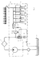
- Fig. 1 a conventional design of a low pressure circuit of a common rail injection system is shown.
- the high-pressure pump 1 has in the standard version an attached mechanical low-pressure prefeed pump 2, which is designed for example as Wegentechnikrad- or internal gear pump and is driven by the camshaft of the high pressure pump and therefore has the same speed.
- the prefeed pump 2 sucks the fuel through a pre-filter 3 with integrated water from the tank 4 and promotes this through the main filter 5 to the low pressure region of the high-pressure pump 1.
- the delivery of the feed pump 2 is usually designed to be larger than the maximum flow of the high-pressure pump 1 to ensure all operating conditions sufficient filling of the high-pressure pump.
- an overflow valve 6 is installed, which has the task to control the excess quantity of the feed pump 2 with respect to the respectively required high-pressure pump delivery.
- a pre-pressure in front of the high-pressure pump 1 sets in according to a pressure-quantity characteristic of the overflow valve.
- the overflow valve is designed as a slide valve, that is, depending on the stroke of the valve piston 7, a Abêtquerites 8 is released.
- the piston 9 of the pressure relief valve 6 is not deflected due to the bias of the spring 9 of the pressure relief valve 6 and thus also not reduced quantity. Only starting from a pressure of approximately 5 bar does a movement take place here and thus an opening of the diversion cross section.
- the delivery rate of the high pressure pump 1 is controlled via a metering unit 10.
- This metering unit 10 consists for example of a slide valve and a linear magnet. Depending on the activation of the linear magnet is over the Slider valve released a certain flow cross-section and thus adjusted the flow rate of the high-pressure pump 1. Due to the design as a slide valve, the metering unit 10 is not tight even in the fully closed state, ie when concerns the Vor fundamentaldrucks there is a leakage amount in the high pressure pump 1 via the gate gap.
- the engine speeds during the engine start process are very low, about 100min -1 , accordingly low are the speeds of the high pressure pump 1 and the pre-feed pump 2.
- the feed pump 2 has at these low speeds due to the games in the conveyor teeth very low conveying efficiencies.
- the metering unit 10 is fully opened in the start case to achieve a maximum flow rate of the high-pressure pump 1 for the pressure build-up in the high-pressure system.
- a large part of the very small flow rate of the feed pump 2 is derived directly via the zero feed throttle 14 back into the non-pressurized return line 15 and is thus not available for the pressure build-up in the high-pressure system.
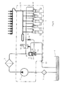
- a check valve 16 which determines the flow through the zero feed line or the zero feed throttle 14.
- the check valve 16 is in this case arranged below the overflow valve 6 and is mechanically opened by the movement of the valve piston 7 of the overflow valve 6.
- the valve closing member of the check valve 16 is mechanically coupled to the valve piston 7 for this purpose.
- the flowing through the zero feed throttle 14 amount is introduced into the spring chamber 17 of the overflow valve.
- the outflow of the introduced amount in the direction of the non-pressurized return line 15 is opened and closed via the non-return valve 16 connected to the spring chamber 17.
- the prefeed pressures are smaller than would be necessary for a movement of the valve piston 7.
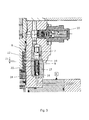
- Fig. 3 shows an exemplary structural design of the overflow valve 6 together with check valve 16, in which the check valve 16 is inserted in the bore below the overflow valve 6.
- the spring 17 of the check valve 16 can be arranged to save space within the spring 9 of the overflow valve 6 or alternatively on the opposite drain side 18.
- a plate 19 is inserted, which the valve closing member of the check valve 16 via a rod 20 after an idle stroke 21 opens.
- This plate 19 is designed with a bore 22 so that the fuel in the valve piston 7 can freely flow in and out.
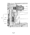
- the spring 9 of the overflow valve 6 is different than in Fig. 3 also used to close the check valve 16:
- the valve closing member 23 of the check valve 16 via a rod 20 with a Plate 19 is connected, which is arranged between the valve piston 7 and the spring 9.
- the overflow valve 6 and the check valve 16 to a unit with only a single spring 24.
- an O-ring 25 is disposed in the check valve 16, which also the tightness between the spring chamber 17 and the pressure-free return 15 ensures.
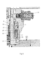
- the flow through the zero feed throttle 14 is controlled via a slide valve.
- a sliding valve seat 27 is realized consisting of the valve piston 7 and the insert 26.
- the zero flow rate is introduced into the spring chamber 17, via the sliding valve seat, the amount is then passed into the piston interior 28 and via a bore 29 in the insert 26 back into the non-pressurized flow 15.
- the insert 26 is designed in the Abêt Scheme with longitudinal grooves 30, so that the valve piston 7 is guided clean.
- the valve piston 7 is not deflected and, accordingly, the sliding valve seat 27 is closed and the flow through the zero-feed throttle 14 is blocked.
- the valve piston 7 is moved and the flow through the zero feed throttle 14 in the non-pressurized return line 15 is released.
Landscapes
- Engineering & Computer Science (AREA)
- Chemical & Material Sciences (AREA)
- Combustion & Propulsion (AREA)
- Mechanical Engineering (AREA)
- General Engineering & Computer Science (AREA)
- Fuel-Injection Apparatus (AREA)
Applications Claiming Priority (1)
| Application Number | Priority Date | Filing Date | Title |
|---|---|---|---|
| ATA1011/2012A AT513154B1 (de) | 2012-09-17 | 2012-09-17 | Niederdruckkreislauf für ein Kraftstoffeinspritzsystem |
Publications (2)
| Publication Number | Publication Date |
|---|---|
| EP2708728A2 true EP2708728A2 (fr) | 2014-03-19 |
| EP2708728A3 EP2708728A3 (fr) | 2016-10-19 |
Family
ID=49115416
Family Applications (1)
| Application Number | Title | Priority Date | Filing Date |
|---|---|---|---|
| EP13183342.8A Withdrawn EP2708728A3 (fr) | 2012-09-17 | 2013-09-06 | Circuit basse pression pour un système d'injection de carburant |
Country Status (3)
| Country | Link |
|---|---|
| US (1) | US20140076281A1 (fr) |
| EP (1) | EP2708728A3 (fr) |
| AT (1) | AT513154B1 (fr) |
Cited By (6)
| Publication number | Priority date | Publication date | Assignee | Title |
|---|---|---|---|---|
| ITUB20160780A1 (it) * | 2016-02-16 | 2017-08-16 | Bosch Gmbh Robert | Connettore per un gruppo pompa di un impianto di alimentazione di combustibile ad un motore a combustione interna, gruppo pompa e impianto di alimentazione |
| CN107288787A (zh) * | 2016-03-31 | 2017-10-24 | 博世汽车柴油系统有限公司 | 燃油喷射系统 |
| CN108150324A (zh) * | 2017-12-27 | 2018-06-12 | 潍柴动力股份有限公司 | 用于发动机燃油系统的高压油泵及发动机燃油系统 |
| WO2019006485A1 (fr) * | 2017-07-05 | 2019-01-10 | Avl List Gmbh | Dispositif de régulation de pression pour système de mesure de consommation de carburant et système de mesure de consommation de carburant |
| AT522135A1 (de) * | 2019-01-22 | 2020-08-15 | Avl List Gmbh | Druckregeleinrichtung für ein Kraftstoffverbrauchsmesssystem |
| WO2025008538A1 (fr) | 2023-07-06 | 2025-01-09 | Robert Bosch Gmbh | Soupape d'étranglement à débit nul |
Families Citing this family (2)
| Publication number | Priority date | Publication date | Assignee | Title |
|---|---|---|---|---|
| CN111219279B (zh) * | 2020-01-08 | 2021-07-09 | 一汽解放汽车有限公司 | 一种具有自保护功能的燃料喷射系统及压力控制方法 |
| US11846246B2 (en) * | 2021-05-27 | 2023-12-19 | Thermo King Llc | Methods and systems for controlling engine inlet pressure via a fuel delivery system of a transport climate control system |
Family Cites Families (9)
| Publication number | Priority date | Publication date | Assignee | Title |
|---|---|---|---|---|
| DE3140948A1 (de) * | 1981-10-15 | 1983-05-05 | Robert Bosch Gmbh, 7000 Stuttgart | Verfahren und kraftstoffeinspritzanlage zur kraftstoffversorgung einer gemischverdichtenden fremdgezuendeten brennkraftmaschine |
| DE19630938C5 (de) * | 1996-07-31 | 2008-02-14 | Siemens Ag | Kraftstoffzuleitung mit einem Volumenstromregelventil und Volumenstromregelventil |
| DE19742180C2 (de) * | 1997-09-24 | 1999-07-08 | Siemens Ag | Einspritzsystem für eine Brennkraftmaschine und Verfahren zum Regeln eines Einspritzsystems |
| DE19926308A1 (de) * | 1999-06-09 | 2000-12-21 | Bosch Gmbh Robert | Pumpenanordnung für Kraftstoff |
| DE10039773A1 (de) * | 2000-08-16 | 2002-02-28 | Bosch Gmbh Robert | Kraftstoffversorgungsanlage |
| WO2005075813A1 (fr) * | 2004-02-06 | 2005-08-18 | Bosch Corporation | Dispositif d’alimentation en carburant |
| DE102006037174A1 (de) * | 2006-08-09 | 2008-02-14 | Robert Bosch Gmbh | Vorrichtung und Verfahren zur Regelung eines Kraftstoffvolumenstroms in einem Niederdruckkreislaufsystem für eine Verbrennungskraftmaschine |
| DE102007052665A1 (de) * | 2007-11-05 | 2009-05-07 | Robert Bosch Gmbh | Kraftstoffüberströmventil für eine Kraftstoffeinspritzeinrichtung und Kraftstoffeinspritzeinrichtung mit Kraftstoffüberströmventil |
| JP2009257200A (ja) * | 2008-04-17 | 2009-11-05 | Bosch Corp | 燃料供給装置 |
-
2012
- 2012-09-17 AT ATA1011/2012A patent/AT513154B1/de not_active IP Right Cessation
-
2013
- 2013-09-06 EP EP13183342.8A patent/EP2708728A3/fr not_active Withdrawn
- 2013-09-16 US US14/028,094 patent/US20140076281A1/en not_active Abandoned
Cited By (12)
| Publication number | Priority date | Publication date | Assignee | Title |
|---|---|---|---|---|
| ITUB20160780A1 (it) * | 2016-02-16 | 2017-08-16 | Bosch Gmbh Robert | Connettore per un gruppo pompa di un impianto di alimentazione di combustibile ad un motore a combustione interna, gruppo pompa e impianto di alimentazione |
| CN107288787A (zh) * | 2016-03-31 | 2017-10-24 | 博世汽车柴油系统有限公司 | 燃油喷射系统 |
| CN107288787B (zh) * | 2016-03-31 | 2020-02-07 | 博世汽车柴油系统有限公司 | 燃油喷射系统 |
| WO2019006485A1 (fr) * | 2017-07-05 | 2019-01-10 | Avl List Gmbh | Dispositif de régulation de pression pour système de mesure de consommation de carburant et système de mesure de consommation de carburant |
| CN110892145A (zh) * | 2017-07-05 | 2020-03-17 | Avl列表有限责任公司 | 用于燃料消耗测量系统的压力调节装置和燃料消耗测量系统 |
| US10954904B2 (en) | 2017-07-05 | 2021-03-23 | Avl List Gmbh | Pressure-regulating device for a fuel consumption measurement system and fuel consumption measurement system |
| CN108150324A (zh) * | 2017-12-27 | 2018-06-12 | 潍柴动力股份有限公司 | 用于发动机燃油系统的高压油泵及发动机燃油系统 |
| CN108150324B (zh) * | 2017-12-27 | 2020-01-03 | 潍柴动力股份有限公司 | 用于发动机燃油系统的高压油泵及发动机燃油系统 |
| AT522135A1 (de) * | 2019-01-22 | 2020-08-15 | Avl List Gmbh | Druckregeleinrichtung für ein Kraftstoffverbrauchsmesssystem |
| AT522135B1 (de) * | 2019-01-22 | 2020-10-15 | Avl List Gmbh | Druckregeleinrichtung für ein Kraftstoffverbrauchsmesssystem |
| WO2025008538A1 (fr) | 2023-07-06 | 2025-01-09 | Robert Bosch Gmbh | Soupape d'étranglement à débit nul |
| DE102023206440A1 (de) | 2023-07-06 | 2025-01-09 | Robert Bosch Gesellschaft mit beschränkter Haftung | Nullförderdrossel |
Also Published As
| Publication number | Publication date |
|---|---|
| US20140076281A1 (en) | 2014-03-20 |
| EP2708728A3 (fr) | 2016-10-19 |
| AT513154A4 (de) | 2014-02-15 |
| AT513154B1 (de) | 2014-02-15 |
Similar Documents
| Publication | Publication Date | Title |
|---|---|---|
| AT513154B1 (de) | Niederdruckkreislauf für ein Kraftstoffeinspritzsystem | |
| EP0455762B1 (fr) | Dispositif de commande electro-hydraulique de soupapes pour moteurs a combustion interne | |
| DE19810867C2 (de) | Kraftstoffpumpen-Anordnung | |
| DE102014005741A1 (de) | Dual-brennstoffeinspritzvorrichtung mit f-, a- und z-zumessöffnungssteuerung | |
| DE19612413A1 (de) | Druckfluid-Versorgungssystem, insbesondere für ein Kraftstoff-Einspritzsystem | |
| DE10057244A1 (de) | Kraftstoffeinspritzanlage für Brennkraftmaschinen mit verbessertem Startverhalten | |
| EP2423498B1 (fr) | Soupape de limitation de débit passive | |
| DE102007010502A1 (de) | Kraftstoffhochdruckpumpe für eine Brennkraftmaschine mit Druckausgleichseinrichtung | |
| DE102018214212A1 (de) | Hochdruck-Kraftstoffpumpe | |
| DE2931944C2 (fr) | ||
| DE102018214030A1 (de) | Hochdruck-kraftstoffpumpe | |
| DE102005022661A1 (de) | Fluidpumpe, insbesondere Kraftstoff-Hochdruckpumpe für eine Brennkraftmaschine mit Kraftstoff-Direkteinspritzung | |
| DE10220281A1 (de) | Kraftstoffpumpe, insbesondere für eine Brennkraftmaschine mit Direkteinspritzung | |
| DE102012223166A1 (de) | Kraftstoffinjektor | |
| DE1951629C3 (de) | Als Rückschlagventil ausgebildetes Einlaßventil für eine Kraftstoffeinspritzpumpe für Brennkraftmaschinen | |
| DE102007032410A1 (de) | Einrichtung zur Kraftstoffversorgung einer Brennkraftmaschine | |
| DE102007011654A1 (de) | Verfahren und Vorrichtung zur Volumenstromregelung eines Einspritzsystems | |
| DE102011082588A1 (de) | Überströmventil mit abgeflachter Kennlinie zur Druckbegrenzung in einem Niederdruckbereich einer Kraftstoffeinspritzvorrichtung | |
| DE102012203258A1 (de) | Kraftstoffsystem einer Brennkraftmaschine | |
| DE102010042582A1 (de) | Überströmventil für ein Kraftstoffeinspritzsystem einer Brennkraftmaschine | |
| DE102011089623A1 (de) | Kraftstofffördereinrichtung für ein Kraftstoffeinspritzsystem sowie Kraftstoffeinspritzsystem | |
| EP1496243B1 (fr) | Moteur à combustion interne | |
| DE19909329A1 (de) | Kraftstoffeinspritzsystem | |
| DE19902292A1 (de) | Fördereinheit | |
| DE1551651A1 (de) | OElfoerderanlage fuer wahlweisen Ein-Strang- oder Zwei-Strang-Betrieb |
Legal Events
| Date | Code | Title | Description |
|---|---|---|---|
| PUAI | Public reference made under article 153(3) epc to a published international application that has entered the european phase |
Free format text: ORIGINAL CODE: 0009012 |
|
| AK | Designated contracting states |
Kind code of ref document: A2 Designated state(s): AL AT BE BG CH CY CZ DE DK EE ES FI FR GB GR HR HU IE IS IT LI LT LU LV MC MK MT NL NO PL PT RO RS SE SI SK SM TR |
|
| AX | Request for extension of the european patent |
Extension state: BA ME |
|
| PUAL | Search report despatched |
Free format text: ORIGINAL CODE: 0009013 |
|
| AK | Designated contracting states |
Kind code of ref document: A3 Designated state(s): AL AT BE BG CH CY CZ DE DK EE ES FI FR GB GR HR HU IE IS IT LI LT LU LV MC MK MT NL NO PL PT RO RS SE SI SK SM TR |
|
| AX | Request for extension of the european patent |
Extension state: BA ME |
|
| RIC1 | Information provided on ipc code assigned before grant |
Ipc: F02M 37/00 20060101AFI20160915BHEP Ipc: F02M 41/16 20060101ALI20160915BHEP |
|
| STAA | Information on the status of an ep patent application or granted ep patent |
Free format text: STATUS: THE APPLICATION IS DEEMED TO BE WITHDRAWN |
|
| 18D | Application deemed to be withdrawn |
Effective date: 20170420 |