EP2708828A2 - Agencement d'appareil de ventilation - Google Patents
Agencement d'appareil de ventilation Download PDFInfo
- Publication number
- EP2708828A2 EP2708828A2 EP13004000.9A EP13004000A EP2708828A2 EP 2708828 A2 EP2708828 A2 EP 2708828A2 EP 13004000 A EP13004000 A EP 13004000A EP 2708828 A2 EP2708828 A2 EP 2708828A2
- Authority
- EP
- European Patent Office
- Prior art keywords
- roof
- ventilation device
- air
- ventilation
- arrangement according
- Prior art date
- Legal status (The legal status is an assumption and is not a legal conclusion. Google has not performed a legal analysis and makes no representation as to the accuracy of the status listed.)
- Granted
Links
Images


Classifications
-
- F—MECHANICAL ENGINEERING; LIGHTING; HEATING; WEAPONS; BLASTING
- F24—HEATING; RANGES; VENTILATING
- F24F—AIR-CONDITIONING; AIR-HUMIDIFICATION; VENTILATION; USE OF AIR CURRENTS FOR SCREENING
- F24F7/00—Ventilation
- F24F7/007—Ventilation with forced flow
-
- F—MECHANICAL ENGINEERING; LIGHTING; HEATING; WEAPONS; BLASTING
- F24—HEATING; RANGES; VENTILATING
- F24F—AIR-CONDITIONING; AIR-HUMIDIFICATION; VENTILATION; USE OF AIR CURRENTS FOR SCREENING
- F24F7/00—Ventilation
- F24F7/02—Roof ventilation
Definitions
- the invention relates to a ventilation device arrangement with a ventilation device having an active air conveyor, and with at least a portion of a roof structure of a roof.
- Ventilation device arrangements of the type mentioned are known from the prior art.
- the ventilation device of such a ventilation device arrangement the ventilation of a room, preferably an interior of the roof and / or at least one other room, a building, in particular a residential building to be performed.
- the ventilation device conveys air from an outside environment of the building or of the roof into the space to be ventilated and / or from the space to be ventilated into the outside environment.
- the active air conveyor is provided, which is present for example as an electrically operated fan or the like.
- the ventilation device arrangement also comprises at least one area of the roof structure.
- the ventilation unit is arranged in the roof structure. It thus engages at least partially in the roof structure.
- the ventilation unit is partially in front of the roof structure and protrudes into an interior of the roof.
- the ventilation unit can be partially present in the roof structure and pass through the roof skin. In the latter case, it is advantageously provided with a cover which sealingly adjoins the areas of the roof skin surrounding the ventilation unit in order to protect the ventilation unit from environmental influences.
- a further embodiment of the invention provides that the roof structure consists of a roof skin, a wall surface delimiting an interior space and a roof construction which is arranged between the roof skin and the wall surface and supports the roof skin, wherein the ventilation device is arranged at least partially in the roof construction.
- the roof covering or roofing usually consists of several roofing elements, such as roof tiles or roof tiles.
- the interior is designed, for example, as a living space.
- the roof skin is usually from the roof construction carried, which consists for example of at least one rafter and / or at least one batten. Of course, however, any type of roof construction may be provided.
- the wall surface is provided on the interior side facing the roof construction.
- This preferably covers the roof structure largely or at least partially so that it is not visible from the interior or only in a few places.
- the roof construction is thus between the wall surface and the roof skin.
- a particularly unobtrusive arrangement of the ventilation device can now be achieved if it is present at least partially in the roof structure, that is, for example, adjacent to the at least one rafter or the at least one roof batten. It is of course particularly advantageous if the ventilation unit, in particular at least the air conveyor, is completely received in the roof construction, that is, neither the wall surface nor the roof skin passes through. Accordingly, the ventilation unit does not protrude into the outside environment or the interior, so that it is neither visible from one nor the other.
- the ventilation device or at least the air conveying device is rather completely covered or enclosed by the roof structure, in particular the roof skin and the wall surface.
- the ventilation device is arranged between two adjacent rafters of the roof and / or on a side facing the interior of resting on the rafters roof battens.
- the ventilation unit is corresponding at least partially in the roof construction in front. It is preferably arranged between two directly adjacent rafters and in particular attached to these. It can be provided that the ventilation device is present below the roof battens, that is arranged on the side facing the interior of the roof battens. The ventilation device can also be attached to at least one of the battens.
- a further embodiment of the invention provides that the ventilation device is arranged adjacent to at least one insulating element of an intermediate spar insulation of the roof.
- the intermediate rafter insulation consists of the at least one insulating element, which is preferably present completely in the roof construction, that is arranged according to its name at least partially, preferably exclusively, between the rafters of the roof. With a corresponding arrangement of the ventilation device, it is thus adjacent to the insulating element, in particular, it adjoins directly to this. In this way, an additional noise insulation of the ventilation unit is achieved.
- a further embodiment of the invention provides for a roof window, in particular a living roof window, attached to the roof structure, in particular to at least one of the rafters, wherein the ventilation device is arranged adjacent to the roof window, in particular adjacent thereto.
- a roof window is usually arranged on the roof structure of the roof.
- a recess in the roof skin and the roof construction is provided in the area of the roof window.
- ventilation of the interior is possible insofar as possible, with a ventilation connection between an outside environment and the interior is present.
- the arrangement of the ventilation unit with respect to the roof window can be chosen arbitrarily, for example, above, below or to the side of the roof window.
- the roof window at least partially encompassing Eindeckrahmen be provided which has at least one connected to the ventilation device air passage.
- the roof window and the roofing frame form a roof window arrangement, which is assigned to the ventilation device arrangement.
- the roofing frame surrounds the roof window at least partially.
- In the area of the covering frame usually no roof skin is provided, but very well the roof construction.
- the flashing frame is, for example, directly on the roof construction, in particular on one or more roof battens, or is arranged at least above them. Preferably, it adjoins on its side facing away from the roof window to the roof skin or overlaps with this.
- a weatherproof, especially rainproof arrangement of the roof window is made possible on the roof.
- the air passage is an air inlet or an air outlet.
- the air inlet air from the outside environment towards the interior, through the air outlet from the interior towards the outside environment promoted.
- the flashing frame on several air outlets, wherein at least one is designed as an air inlet and at least one other than air outlet.
- the air inlet and the air outlet are preferably arranged on the same side of the roof window.
- a development of the invention provides that the ventilation device is at least partially disposed under the Eindeckrahmen. In other words, the ventilation device is thus at least partially covered by the Eindeckrahmen. This means that in the area of the ventilation unit no roof skin is present in the true sense, but the protection of the ventilation unit is realized against environmental influences by means of Eindeckrahmens.
- Such an arrangement of the ventilation device allows easy installation, because the ventilation unit in an area in which there is no roof, introduced into the roof structure or the roof structure and subsequently the Eindeckrahmen can be attached so that the ventilation unit is covered.
- the flashing frame has at least one maintenance and / or installation access for the ventilation device.
- the entire ventilation unit can be removed or used through the maintenance and / or installation access to allow in this way a simple installation or a simple exchange.
- An advantageous development of the invention provides an inner lining for connecting the roof window with the wall surface bounding the interior space, wherein the inner lining engages through the wall surface and has at least one or a further maintenance and / or installation access for the ventilation device.
- the lining can also be called a window reveal.
- the inner lining usually passes through the roof structure, in particular the roof construction, at least partially. About the inner lining a visually appealing connection of the roof window to the roof construction in the direction of the interior bounding wall surface is achieved. The inner lining also penetrates the wall surface. Consequently, access to the roof window from the interior is possible through an opening delimited by the inner lining.
- a further embodiment of the invention provides that the ventilation unit consists of a device chassis and a device insert, wherein the device insert is releasably secured in the device chassis and at least one air duct of the device insert is in flow communication with the arrangement of the device insert in the device chassis with an air duct of the device chassis.
- the ventilation unit is thus designed in several parts, wherein it has at least the device chassis and the device insert.
- an exchange of active components of the ventilation device in particular the air conveyor, particularly simple to carry out, because they are located in the device insert.
- the device insert is releasably secured in the device chassis.
- the device chassis is permanently held on the roof, in particular on the roof structure.
- the device insert is arranged under the above-described maintenance and / or installation access, so that it can be easily removed and reused by it.
- the device chassis and the device insert each have an air duct, said air ducts after insertion of the device insert into the device chassis in fluid communication with each other. This is achieved, for example, by the air ducts are aligned.
- a seal assembly is mounted so that there is a tight flow connection from the air duct of the device insert to the air duct of the device chassis after arranging the device insert in the device chassis without further manipulation.
- the device chassis has a passage opening for the appliance insert, which is encompassed by a seal, in particular a film, wherein the seal is fastened with its one side to the device chassis and on its other side for attachment is formed on a vapor barrier of the roof.
- a seal in particular a film
- the seal is fastened with its one side to the device chassis and on its other side for attachment is formed on a vapor barrier of the roof.
- the seal means for their attachment to the vapor barrier of the roof are provided on the side facing away from the device chassis of the seal means for their attachment to the vapor barrier of the roof.
- the assembly of the device chassis can thus be done, for example, first by the use of equipment.
- the device chassis is arranged in the roof structure and fastened there. following the seal, which is preferably already pre-assembled on the device chassis, attached by suitable means to the vapor barrier of the roof, in the simplest case by pressing, so there is a tight connection to this. Subsequently, the device insert can be inserted into the device chassis.
- the means for attaching the seal to the vapor barrier include, for example, an adhesive coating.
- the ventilation unit promotes air from an external environment into the interior via an air supply line and air from the interior to the outside environment via an exhaust air line.
- the ventilation device may have at least two, as the supply air and the exhaust duct formed air channels, which are heat transfer coupled via a heat exchanger, in particular a rotary heat exchanger.
- the supply air line and / or the exhaust air line in the ventilation device preferably have at least one 180 ° deflection.
- the supply air line is connected to the air inlet and the exhaust air line to the air outlet, for example.
- the ventilation device is preferably formed with heat recovery means comprising the heat exchanger.
- Such heat exchangers normally operate according to the countercurrent process, wherein a supply air flow flowing through the supply air line and an exhaust air flow flowing through the exhaust air line are guided in opposite directions. Accordingly, the interior and the exterior of the environment facing ports of the ventilation unit are each arranged on the same side.
- the supply air line, the exhaust air line or both each 180 ° deflection, which is formed in the ventilation unit.
- Such an embodiment is particularly advantageous if a plurality of air passages are provided on the flashing frame. In this case, the connection of the ventilation unit can be performed on this with comparatively short air ducts or pipes.
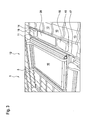
- FIG. 1 shows a plan view of an area of a roof 1, of which a roof structure 2, consisting of only exemplarily marked rafters 3 and battens 4, are shown.
- At least part of the roof structure 7 together with a ventilation device 8 represents a ventilation device arrangement 9.
- the ventilation device 8 is divided into three different ones , shown selectable positions, namely both above and below and laterally of a roof window 10.
- the roof window 10 and a cover frame 11, not shown here form a roof window assembly 12th
- the ventilation device 8 For space-saving and visually inconspicuous arrangement of the ventilation device 8, it is provided to accommodate this in the roof structure 7. This means that the ventilation device 8 at least partially protrudes into this. It is particularly advantageous if the ventilation device 8, in particular an air conveying device of the ventilation device 8, is completely present in the roof structure 7 or even completely in the roof structure 2. At least the ventilation devices 8, which are indicated above and below the roof window 10, lie between two directly adjacent rafters 3. At the same time they are arranged on a side facing the interior of the battens 4, which rest on the rafters 3. Alternatively, however, it can also be provided that the ventilation device 8 at least partially penetrates at least one of the rafters 3. This is shown by the arrangement of the ventilation device 8 to the right of the roof window 10.
- FIG. 2 shows a view of the from the FIG. 1 known area of the roof 1 from below or from above.
- the ventilation device 8 in any of the two arrangements shown in the direction away from the roof window 10 direction over the rafters 3 protrudes, so in particular does not protrude into the interior of the roof 1.
- the dimensions of the ventilation device 8 are selected in such a way that it can be arranged completely in the roof structure 2 and neither protrudes in the direction of the roof skin 5 in the direction of the wall surface 6 on the rafters 3. Overall, an optically inconspicuous and space-saving arrangement of the ventilation unit 8 is thus realized.
- FIG. 3 shows a portion of the roof 1, wherein the roof structure 2 is not visible because it is covered by the roof skin 5, which consists of roofing elements 13, such as roof tiles or roof tiles.
- the roof window 10 of the roof window assembly 12 is arranged together with the Eindeckrahmen 11.
- the region of Eindeckrahmens 11 is no roof skin 5, but probably the roof structure 2 before.
- the flashing frame 11 rests directly on the roof battens 4.
- the flashing frame 11 has two air passages 14 and 15, wherein the air passage 14 is formed as an air inlet and the air passage 15 as an air outlet.
- Each of the air outlets 14 and 15 has an air scoop 16, which projects over a base element 17 of the flashing frame 11 in the direction away from the roof 1 at least partially.
- the air inlets 14 and 15 are each connected via an air duct to the ventilation unit 8.
- the air channel between the air inlet 14 and the ventilation device 8 forms part of a supply air line 18, via which air from the outside environment can be conveyed into the interior. Accordingly, the line between the air outlet 15 and the ventilation device 8 forms part of an exhaust duct 19, through which air can be conveyed from the interior to the outside environment.
- the ventilation device 8 is at least partially disposed under the Eindeckrahmen 11 or is covered by this.
- the Eindeckrahmen 11 has a maintenance and / or installation access 20.
- the ventilation unit 8 is at least partially removable or replaceable.
- FIG. 4 shows a side sectional view of a portion of the roof 1, wherein a section through the Eindeckrahmen 11 is shown. It It is again clear that the ventilation unit 8 projects beyond the rafters 3 neither in the direction of the interior nor in the direction of the outside environment. It preferably has dimensions which allow removal through the maintenance and / or installation access 20.
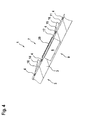
- the FIG. 5 shows a device chassis 21 of the ventilation unit 8. This forms together with a device insert, not shown here, the ventilation unit 8.
- the device insert is in an insert receptacle 22 which is accessible through a passage opening 23, can be used.
- the device chassis 21 has a plurality of air connections 24, 25, 26 and 27, of which two are each part of the supply air line 18 and the exhaust air line 19.
- the device insert also has air connections, which are aligned with the air connections 24 to 27, so that after insertion of the device insert in the device chassis 21 and its insert receptacle 22 is a tight connection of each of the air connections 24 to 27 to the respective associated air connection of the device insert.
- the former is designed trapezoidal, for example, in cross section.
- the air connection 24 is connected, for example, to the air inlet 14, so that air sucked from the outside environment enters through it into the device chassis 21 or the appliance insert and is tempered therein. Subsequently, the so-tempered air exits through the air connection 25 in the direction of the interior of the ventilation unit 8. Conversely, for example, air is sucked from the interior and fed through the air connection 27 to the ventilation unit 8. The air is after passing through the Ventilation device 8 through the air outlet 15, which is connected to the air connection 26, discharged into the outside environment.
- a seal 28 is already mounted preassembled around the passage opening 23 around.
- the seal 28 surrounds the passage opening 23 at least partially. It is attached on its one side 29 to the device chassis 21 and has on its other side 30 not shown here means for attachment to a vapor barrier also not shown the roof 1.
- These agents may for example have an adhesive coating, so after inserting the device chassis 21 in the roof structure 7 only an adhesive bond between the seal 28 and the vapor barrier by pressing the seal 28 is to produce this.
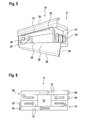
- FIG. 6 shows a schematic representation of the ventilation unit 8. It is clear that the air connections 24 and 25 are present in the supply air line 18 or train them with. The air connections 26 and 27, however, are in the exhaust duct 19 before or form this with.
- a heat exchanger 31 is provided, by means of which the air flows flowing through the supply air line 18 and the exhaust air line 19 are tempered. For example, cool air from the outside environment is supplied through the air port 24, which is heated with heat taken from the warm air supplied through the air port 27 from the interior. Subsequently, the thus heated air is discharged through the air port 25 into the interior and the cooled air from the air port 26 in the outside environment.
- the heat exchanger 31 is particularly preferably designed as a rotary heat exchanger. It can be clearly seen that the air connections 24 and 25 and the air connections 26 and 27 are each arranged on the same side of the ventilation device 8. For this purpose, in each case a deflection 32 or 33 is provided both in the supply air line 18 and in the exhaust air line 19, which are formed for example as 180 ° deflections. Due to these deflections 32 and 33, air that has passed through the heat exchanger 31, deflected so that it again passes almost the entire length of the ventilation unit 8. However, in each case it is guided past the heat exchanger 31, so it does not pass through it again.
- the FIG. 7 shows an inner lining 34, which can also be referred to as a window reveal.
- the inner lining is used to establish a connection of the roof window 10, which is merely indicated here, with the wall surface 6, which delimits the interior of the roof 1.
- the inner lining 34 passes through the wall surface 6 coming from the outside environment in the direction of the interior. Accordingly, the inner lining 34 or an area encompassed by this area provides access from the interior to the roof window 10.
- the inner lining 34 has a further maintenance and / or installation access 35, which is merely shown here by way of example, through which access to the ventilation device 8 is possible.
- the ventilation unit 8 and its use of equipment through the maintenance and / or installation access 20 or 35 to remove and reinsert.
- a simple interchangeability of the device use or individual parts of this is possible.
- FIG. 8 shows by way of example the region of the inner lining 34, in which the maintenance and / or installation access 35 is provided. It becomes clear that this can be closed with a closing element 36, which is designed, for example, as a flap and is pivotally mounted on the inner lining 34 in this respect.
- a closing element 36 which is designed, for example, as a flap and is pivotally mounted on the inner lining 34 in this respect.
- a snap closure 37 is provided, which holds the closure element 36 in position.
- the latching closure 37 urges the closure element 36 against a holding element 38 which is provided on the side of the inner lining 34 facing the ventilation device 8 (not shown).
Landscapes
- Engineering & Computer Science (AREA)
- Chemical & Material Sciences (AREA)
- Combustion & Propulsion (AREA)
- Mechanical Engineering (AREA)
- General Engineering & Computer Science (AREA)
- Building Environments (AREA)
Applications Claiming Priority (1)
| Application Number | Priority Date | Filing Date | Title |
|---|---|---|---|
| DE102012016349.5A DE102012016349A1 (de) | 2012-08-16 | 2012-08-16 | Lüftungsgeräteanordnung |
Publications (3)
| Publication Number | Publication Date |
|---|---|
| EP2708828A2 true EP2708828A2 (fr) | 2014-03-19 |
| EP2708828A3 EP2708828A3 (fr) | 2017-12-06 |
| EP2708828B1 EP2708828B1 (fr) | 2020-07-29 |
Family
ID=49028877
Family Applications (1)
| Application Number | Title | Priority Date | Filing Date |
|---|---|---|---|
| EP13004000.9A Active EP2708828B1 (fr) | 2012-08-16 | 2013-08-10 | Agencement d'appareil de ventilation |
Country Status (2)
| Country | Link |
|---|---|
| EP (1) | EP2708828B1 (fr) |
| DE (1) | DE102012016349A1 (fr) |
Cited By (1)
| Publication number | Priority date | Publication date | Assignee | Title |
|---|---|---|---|---|
| US11788743B2 (en) * | 2014-03-06 | 2023-10-17 | O'daniels, Llc. | Roof vent with an integrated fan |
Family Cites Families (10)
| Publication number | Priority date | Publication date | Assignee | Title |
|---|---|---|---|---|
| DE20221839U1 (de) * | 1977-10-29 | 2008-06-26 | Vkr Holding A/S | Fenster mit Lüftungsöffnung |
| DE29804416U1 (de) * | 1998-03-12 | 1998-06-04 | MAGE GmbH Werke für Kunststoff- und Metallverarbeitung, 72250 Freudenstadt | Fenster mit Lüftungseinrichtung |
| US6695692B1 (en) * | 2003-01-20 | 2004-02-24 | Ronald V York | Curb mount skylight and solar fan combination unit |
| DE102004037563A1 (de) * | 2004-08-03 | 2006-03-16 | Christian Boden | Dachfensterintegriertes Solar-Lüftungssystem |
| DE102004052936A1 (de) * | 2004-10-29 | 2006-05-04 | Dieter Heitzler | Vorrichtung zur Kühlung von Dachräumen in Gebäuden mit geneigter Dachfläche |
| US20070243820A1 (en) * | 2006-04-18 | 2007-10-18 | O'hagin Carolina | Automatic roof ventilation system |
| DE202007011819U1 (de) * | 2007-08-24 | 2009-01-08 | SCHÜCO International KG | Lüftung an Doppelfassade |
| CA2788227C (fr) * | 2010-01-27 | 2018-01-16 | Thomas Bushey | Systeme de ventilateur a event alimente par le soleil et kit de pieces |
| US20110217194A1 (en) * | 2010-03-05 | 2011-09-08 | Randall Peter L | Solar-powered soffit fan |
| US20120045983A1 (en) * | 2010-08-18 | 2012-02-23 | Eskola Iii Edward Walfred | Solar Powered Active Roof Ridge Vent |
-
2012
- 2012-08-16 DE DE102012016349.5A patent/DE102012016349A1/de not_active Ceased
-
2013
- 2013-08-10 EP EP13004000.9A patent/EP2708828B1/fr active Active
Non-Patent Citations (1)
| Title |
|---|
| None |
Cited By (1)
| Publication number | Priority date | Publication date | Assignee | Title |
|---|---|---|---|---|
| US11788743B2 (en) * | 2014-03-06 | 2023-10-17 | O'daniels, Llc. | Roof vent with an integrated fan |
Also Published As
| Publication number | Publication date |
|---|---|
| EP2708828B1 (fr) | 2020-07-29 |
| DE102012016349A1 (de) | 2014-03-20 |
| EP2708828A3 (fr) | 2017-12-06 |
Similar Documents
| Publication | Publication Date | Title |
|---|---|---|
| EP2594725B1 (fr) | Fenêtre | |
| DE102004004197B4 (de) | Zweiteilig ausgebildete Dachstruktur | |
| DE2630667A1 (de) | Klima-dachgeraet | |
| DE102009057355B4 (de) | Lüftungseinrichtung zum Zuführen und/oder Abführen von Luft | |
| WO2010026049A1 (fr) | Véhicule ferroviaire pouvant être commuté entre un mode hiver et un mode été | |
| DE102010042950A1 (de) | Dezentrale Raumlüftungsvorrichtung mit Wärmerückgewinnung | |
| EP2708828B1 (fr) | Agencement d'appareil de ventilation | |
| DE3040739A1 (de) | Anordnung zur abluftwaermerueckgewinnung | |
| DE102015101510A1 (de) | Fassadenanschlusseinrichtung für eine Lüftungseinrichtung sowie Lüftungseinrichtung | |
| EP2698497B1 (fr) | Agencement de fenêtre comprenant une doublure intérieure | |
| EP1772679B1 (fr) | Appareil décentralisé de traitement de l'air d'une pièce | |
| DE102013114085A1 (de) | Lüftungsgerät zur Raumlüftung | |
| DE102009017053A1 (de) | Wärmetauschervorrichtung | |
| DE102011002605B4 (de) | Dezentrale Raumlüftungsvorrichtung mit Wärmerückgewinnung | |
| EP2161512B1 (fr) | Appareil d'aération décentralisé et installation d'aération dotée d'un tel appareil | |
| DE20200246U1 (de) | Anordnung zur Erzeugung eines Luftschottes | |
| DE3103458A1 (de) | Mauerkasten | |
| DE3248227A1 (de) | Umlaufende einfassung fuer tueren oder fenster, sowie kastenbauteil, insbesondere rolladenkasten, zur verwendung oberhalb der einfassung | |
| EP1840478B1 (fr) | Surface autour d'une fenêtre | |
| DE202019100467U1 (de) | Lufteinlass und Anordnung zur Führung von Luft | |
| EP2792961B1 (fr) | Module d'échangeur de chaleur | |
| DE102011016871B4 (de) | Sicht- oder Lärmschutzwand | |
| EP2857772A1 (fr) | Appareil d'aération avec récupération de chaleur | |
| EP2698485B1 (fr) | Agencement de fenêtre de toit | |
| DE202006013263U1 (de) | Solarkollektor mit einem belüftbaren Gehäuse |
Legal Events
| Date | Code | Title | Description |
|---|---|---|---|
| PUAI | Public reference made under article 153(3) epc to a published international application that has entered the european phase |
Free format text: ORIGINAL CODE: 0009012 |
|
| AK | Designated contracting states |
Kind code of ref document: A2 Designated state(s): AL AT BE BG CH CY CZ DE DK EE ES FI FR GB GR HR HU IE IS IT LI LT LU LV MC MK MT NL NO PL PT RO RS SE SI SK SM TR |
|
| AX | Request for extension of the european patent |
Extension state: BA ME |
|
| PUAL | Search report despatched |
Free format text: ORIGINAL CODE: 0009013 |
|
| AK | Designated contracting states |
Kind code of ref document: A3 Designated state(s): AL AT BE BG CH CY CZ DE DK EE ES FI FR GB GR HR HU IE IS IT LI LT LU LV MC MK MT NL NO PL PT RO RS SE SI SK SM TR |
|
| AX | Request for extension of the european patent |
Extension state: BA ME |
|
| RIC1 | Information provided on ipc code assigned before grant |
Ipc: F24F 7/007 20060101AFI20171102BHEP Ipc: F24F 7/02 20060101ALI20171102BHEP |
|
| STAA | Information on the status of an ep patent application or granted ep patent |
Free format text: STATUS: REQUEST FOR EXAMINATION WAS MADE |
|
| 17P | Request for examination filed |
Effective date: 20180606 |
|
| RBV | Designated contracting states (corrected) |
Designated state(s): AL AT BE BG CH CY CZ DE DK EE ES FI FR GB GR HR HU IE IS IT LI LT LU LV MC MK MT NL NO PL PT RO RS SE SI SK SM TR |
|
| STAA | Information on the status of an ep patent application or granted ep patent |
Free format text: STATUS: EXAMINATION IS IN PROGRESS |
|
| 17Q | First examination report despatched |
Effective date: 20190920 |
|
| RAP1 | Party data changed (applicant data changed or rights of an application transferred) |
Owner name: ROTO FRANK DST MARKEN GMBH & CO. KG |
|
| GRAP | Despatch of communication of intention to grant a patent |
Free format text: ORIGINAL CODE: EPIDOSNIGR1 |
|
| STAA | Information on the status of an ep patent application or granted ep patent |
Free format text: STATUS: GRANT OF PATENT IS INTENDED |
|
| INTG | Intention to grant announced |
Effective date: 20200214 |
|
| GRAS | Grant fee paid |
Free format text: ORIGINAL CODE: EPIDOSNIGR3 |
|
| GRAA | (expected) grant |
Free format text: ORIGINAL CODE: 0009210 |
|
| STAA | Information on the status of an ep patent application or granted ep patent |
Free format text: STATUS: THE PATENT HAS BEEN GRANTED |
|
| AK | Designated contracting states |
Kind code of ref document: B1 Designated state(s): AL AT BE BG CH CY CZ DE DK EE ES FI FR GB GR HR HU IE IS IT LI LT LU LV MC MK MT NL NO PL PT RO RS SE SI SK SM TR |
|
| REG | Reference to a national code |
Ref country code: GB Ref legal event code: FG4D Free format text: NOT ENGLISH |
|
| REG | Reference to a national code |
Ref country code: CH Ref legal event code: EP |
|
| REG | Reference to a national code |
Ref country code: DE Ref legal event code: R096 Ref document number: 502013014954 Country of ref document: DE |
|
| REG | Reference to a national code |
Ref country code: AT Ref legal event code: REF Ref document number: 1296253 Country of ref document: AT Kind code of ref document: T Effective date: 20200815 |
|
| REG | Reference to a national code |
Ref country code: IE Ref legal event code: FG4D Free format text: LANGUAGE OF EP DOCUMENT: GERMAN |
|
| REG | Reference to a national code |
Ref country code: LT Ref legal event code: MG4D |
|
| REG | Reference to a national code |
Ref country code: NL Ref legal event code: MP Effective date: 20200729 |
|
| PG25 | Lapsed in a contracting state [announced via postgrant information from national office to epo] |
Ref country code: PT Free format text: LAPSE BECAUSE OF FAILURE TO SUBMIT A TRANSLATION OF THE DESCRIPTION OR TO PAY THE FEE WITHIN THE PRESCRIBED TIME-LIMIT Effective date: 20201130 Ref country code: FI Free format text: LAPSE BECAUSE OF FAILURE TO SUBMIT A TRANSLATION OF THE DESCRIPTION OR TO PAY THE FEE WITHIN THE PRESCRIBED TIME-LIMIT Effective date: 20200729 Ref country code: NO Free format text: LAPSE BECAUSE OF FAILURE TO SUBMIT A TRANSLATION OF THE DESCRIPTION OR TO PAY THE FEE WITHIN THE PRESCRIBED TIME-LIMIT Effective date: 20201029 Ref country code: SE Free format text: LAPSE BECAUSE OF FAILURE TO SUBMIT A TRANSLATION OF THE DESCRIPTION OR TO PAY THE FEE WITHIN THE PRESCRIBED TIME-LIMIT Effective date: 20200729 Ref country code: BG Free format text: LAPSE BECAUSE OF FAILURE TO SUBMIT A TRANSLATION OF THE DESCRIPTION OR TO PAY THE FEE WITHIN THE PRESCRIBED TIME-LIMIT Effective date: 20201029 Ref country code: HR Free format text: LAPSE BECAUSE OF FAILURE TO SUBMIT A TRANSLATION OF THE DESCRIPTION OR TO PAY THE FEE WITHIN THE PRESCRIBED TIME-LIMIT Effective date: 20200729 Ref country code: GR Free format text: LAPSE BECAUSE OF FAILURE TO SUBMIT A TRANSLATION OF THE DESCRIPTION OR TO PAY THE FEE WITHIN THE PRESCRIBED TIME-LIMIT Effective date: 20201030 Ref country code: ES Free format text: LAPSE BECAUSE OF FAILURE TO SUBMIT A TRANSLATION OF THE DESCRIPTION OR TO PAY THE FEE WITHIN THE PRESCRIBED TIME-LIMIT Effective date: 20200729 Ref country code: LT Free format text: LAPSE BECAUSE OF FAILURE TO SUBMIT A TRANSLATION OF THE DESCRIPTION OR TO PAY THE FEE WITHIN THE PRESCRIBED TIME-LIMIT Effective date: 20200729 |
|
| PG25 | Lapsed in a contracting state [announced via postgrant information from national office to epo] |
Ref country code: PL Free format text: LAPSE BECAUSE OF FAILURE TO SUBMIT A TRANSLATION OF THE DESCRIPTION OR TO PAY THE FEE WITHIN THE PRESCRIBED TIME-LIMIT Effective date: 20200729 Ref country code: LV Free format text: LAPSE BECAUSE OF FAILURE TO SUBMIT A TRANSLATION OF THE DESCRIPTION OR TO PAY THE FEE WITHIN THE PRESCRIBED TIME-LIMIT Effective date: 20200729 Ref country code: RS Free format text: LAPSE BECAUSE OF FAILURE TO SUBMIT A TRANSLATION OF THE DESCRIPTION OR TO PAY THE FEE WITHIN THE PRESCRIBED TIME-LIMIT Effective date: 20200729 Ref country code: IS Free format text: LAPSE BECAUSE OF FAILURE TO SUBMIT A TRANSLATION OF THE DESCRIPTION OR TO PAY THE FEE WITHIN THE PRESCRIBED TIME-LIMIT Effective date: 20201129 |
|
| PG25 | Lapsed in a contracting state [announced via postgrant information from national office to epo] |
Ref country code: NL Free format text: LAPSE BECAUSE OF FAILURE TO SUBMIT A TRANSLATION OF THE DESCRIPTION OR TO PAY THE FEE WITHIN THE PRESCRIBED TIME-LIMIT Effective date: 20200729 |
|
| REG | Reference to a national code |
Ref country code: CH Ref legal event code: PL |
|
| PG25 | Lapsed in a contracting state [announced via postgrant information from national office to epo] |
Ref country code: LI Free format text: LAPSE BECAUSE OF NON-PAYMENT OF DUE FEES Effective date: 20200831 Ref country code: IT Free format text: LAPSE BECAUSE OF FAILURE TO SUBMIT A TRANSLATION OF THE DESCRIPTION OR TO PAY THE FEE WITHIN THE PRESCRIBED TIME-LIMIT Effective date: 20200729 Ref country code: EE Free format text: LAPSE BECAUSE OF FAILURE TO SUBMIT A TRANSLATION OF THE DESCRIPTION OR TO PAY THE FEE WITHIN THE PRESCRIBED TIME-LIMIT Effective date: 20200729 Ref country code: DK Free format text: LAPSE BECAUSE OF FAILURE TO SUBMIT A TRANSLATION OF THE DESCRIPTION OR TO PAY THE FEE WITHIN THE PRESCRIBED TIME-LIMIT Effective date: 20200729 Ref country code: CZ Free format text: LAPSE BECAUSE OF FAILURE TO SUBMIT A TRANSLATION OF THE DESCRIPTION OR TO PAY THE FEE WITHIN THE PRESCRIBED TIME-LIMIT Effective date: 20200729 Ref country code: CH Free format text: LAPSE BECAUSE OF NON-PAYMENT OF DUE FEES Effective date: 20200831 Ref country code: SM Free format text: LAPSE BECAUSE OF FAILURE TO SUBMIT A TRANSLATION OF THE DESCRIPTION OR TO PAY THE FEE WITHIN THE PRESCRIBED TIME-LIMIT Effective date: 20200729 Ref country code: RO Free format text: LAPSE BECAUSE OF FAILURE TO SUBMIT A TRANSLATION OF THE DESCRIPTION OR TO PAY THE FEE WITHIN THE PRESCRIBED TIME-LIMIT Effective date: 20200729 Ref country code: LU Free format text: LAPSE BECAUSE OF NON-PAYMENT OF DUE FEES Effective date: 20200810 Ref country code: MC Free format text: LAPSE BECAUSE OF FAILURE TO SUBMIT A TRANSLATION OF THE DESCRIPTION OR TO PAY THE FEE WITHIN THE PRESCRIBED TIME-LIMIT Effective date: 20200729 |
|
| REG | Reference to a national code |
Ref country code: DE Ref legal event code: R097 Ref document number: 502013014954 Country of ref document: DE |
|
| REG | Reference to a national code |
Ref country code: BE Ref legal event code: MM Effective date: 20200831 |
|
| PG25 | Lapsed in a contracting state [announced via postgrant information from national office to epo] |
Ref country code: AL Free format text: LAPSE BECAUSE OF FAILURE TO SUBMIT A TRANSLATION OF THE DESCRIPTION OR TO PAY THE FEE WITHIN THE PRESCRIBED TIME-LIMIT Effective date: 20200729 |
|
| PLBE | No opposition filed within time limit |
Free format text: ORIGINAL CODE: 0009261 |
|
| STAA | Information on the status of an ep patent application or granted ep patent |
Free format text: STATUS: NO OPPOSITION FILED WITHIN TIME LIMIT |
|
| GBPC | Gb: european patent ceased through non-payment of renewal fee |
Effective date: 20201029 |
|
| PG25 | Lapsed in a contracting state [announced via postgrant information from national office to epo] |
Ref country code: SK Free format text: LAPSE BECAUSE OF FAILURE TO SUBMIT A TRANSLATION OF THE DESCRIPTION OR TO PAY THE FEE WITHIN THE PRESCRIBED TIME-LIMIT Effective date: 20200729 |
|
| 26N | No opposition filed |
Effective date: 20210430 |
|
| PG25 | Lapsed in a contracting state [announced via postgrant information from national office to epo] |
Ref country code: FR Free format text: LAPSE BECAUSE OF NON-PAYMENT OF DUE FEES Effective date: 20200929 |
|
| PG25 | Lapsed in a contracting state [announced via postgrant information from national office to epo] |
Ref country code: GB Free format text: LAPSE BECAUSE OF NON-PAYMENT OF DUE FEES Effective date: 20201029 Ref country code: IE Free format text: LAPSE BECAUSE OF NON-PAYMENT OF DUE FEES Effective date: 20200810 Ref country code: SI Free format text: LAPSE BECAUSE OF FAILURE TO SUBMIT A TRANSLATION OF THE DESCRIPTION OR TO PAY THE FEE WITHIN THE PRESCRIBED TIME-LIMIT Effective date: 20200729 Ref country code: BE Free format text: LAPSE BECAUSE OF NON-PAYMENT OF DUE FEES Effective date: 20200831 |
|
| REG | Reference to a national code |
Ref country code: AT Ref legal event code: MM01 Ref document number: 1296253 Country of ref document: AT Kind code of ref document: T Effective date: 20200810 |
|
| PG25 | Lapsed in a contracting state [announced via postgrant information from national office to epo] |
Ref country code: AT Free format text: LAPSE BECAUSE OF NON-PAYMENT OF DUE FEES Effective date: 20200810 |
|
| PG25 | Lapsed in a contracting state [announced via postgrant information from national office to epo] |
Ref country code: TR Free format text: LAPSE BECAUSE OF FAILURE TO SUBMIT A TRANSLATION OF THE DESCRIPTION OR TO PAY THE FEE WITHIN THE PRESCRIBED TIME-LIMIT Effective date: 20200729 Ref country code: MT Free format text: LAPSE BECAUSE OF FAILURE TO SUBMIT A TRANSLATION OF THE DESCRIPTION OR TO PAY THE FEE WITHIN THE PRESCRIBED TIME-LIMIT Effective date: 20200729 Ref country code: CY Free format text: LAPSE BECAUSE OF FAILURE TO SUBMIT A TRANSLATION OF THE DESCRIPTION OR TO PAY THE FEE WITHIN THE PRESCRIBED TIME-LIMIT Effective date: 20200729 |
|
| PG25 | Lapsed in a contracting state [announced via postgrant information from national office to epo] |
Ref country code: MK Free format text: LAPSE BECAUSE OF FAILURE TO SUBMIT A TRANSLATION OF THE DESCRIPTION OR TO PAY THE FEE WITHIN THE PRESCRIBED TIME-LIMIT Effective date: 20200729 |
|
| PGFP | Annual fee paid to national office [announced via postgrant information from national office to epo] |
Ref country code: DE Payment date: 20250819 Year of fee payment: 13 |