EP2708904A2 - Dispositif de détermination d'un courant électrique continu dans un conducteur électrique - Google Patents
Dispositif de détermination d'un courant électrique continu dans un conducteur électrique Download PDFInfo
- Publication number
- EP2708904A2 EP2708904A2 EP13183070.5A EP13183070A EP2708904A2 EP 2708904 A2 EP2708904 A2 EP 2708904A2 EP 13183070 A EP13183070 A EP 13183070A EP 2708904 A2 EP2708904 A2 EP 2708904A2
- Authority
- EP
- European Patent Office
- Prior art keywords
- current
- display
- conductor
- display unit
- electrical conductor
- Prior art date
- Legal status (The legal status is an assumption and is not a legal conclusion. Google has not performed a legal analysis and makes no representation as to the accuracy of the status listed.)
- Withdrawn
Links
- 239000004020 conductor Substances 0.000 title claims abstract description 69
- 230000005291 magnetic effect Effects 0.000 claims abstract description 22
- 239000003302 ferromagnetic material Substances 0.000 claims description 2
- 230000005294 ferromagnetic effect Effects 0.000 description 3
- 238000010276 construction Methods 0.000 description 2
- 238000012423 maintenance Methods 0.000 description 2
- 230000000452 restraining effect Effects 0.000 description 2
- 230000001419 dependent effect Effects 0.000 description 1
- 238000011161 development Methods 0.000 description 1
- 230000018109 developmental process Effects 0.000 description 1
- 230000006698 induction Effects 0.000 description 1
- 238000009413 insulation Methods 0.000 description 1
- 238000000034 method Methods 0.000 description 1
- 230000002441 reversible effect Effects 0.000 description 1
- 238000004088 simulation Methods 0.000 description 1
Images


Classifications
-
- G—PHYSICS
- G01—MEASURING; TESTING
- G01R—MEASURING ELECTRIC VARIABLES; MEASURING MAGNETIC VARIABLES
- G01R19/00—Arrangements for measuring currents or voltages or for indicating presence or sign thereof
- G01R19/145—Indicating the presence of current or voltage
- G01R19/15—Indicating the presence of current
Definitions
- the invention relates to a device for detecting a direct electrical current in an electrical conductor, which comprises a receiving area in which the electrical conductor is at least partially accommodated when the device is attached to the conductor. Furthermore, the device has a display unit for optically indicating the presence of a direct electrical current in the conductor.
- devices for determining direct electrical currents which require direct contact with the conductor through which current flows, in order to determine the electric current flow and visually indicate this to an operator.
- devices which can determine the presence of the electric current without contact.
- Such devices have, in particular, magnetic sensors, for example Hall sensors or magnetic resistors, with the aid of which it is determined whether current flows through the electrical conductor or not.
- a disadvantage of such known non-contact devices is that These need their own power supply, eg via a battery. It is necessary that the battery is changed regularly. If this is not the case, the devices can not indicate whether or not the conductor has the electric current flowing through them, so that there is a safety risk for the person.
- the device is designed such that a force necessary for adjusting the display unit is caused by a magnetic field generated by the direct current of the conductor.
- the energy required for display by the display unit is transmitted contactlessly from the conductor to the device.
- the device Compared with known devices in which a direct contact with the current-carrying conductor is necessary to determine the presence of a current, the device has the advantage that just such direct contact must be made, whereby the operating safety is increased.
- the device is preferably designed such that the energy can be transmitted by induction from the electrical conductor to the device. Thus, a particularly simple safe energy transfer is achieved.
- the display unit comprises at least one rotatable about an axis of rotation rotatably mounted rotary member which is arranged in a first position when the electrical conductor is traversed by a direct current with a first current strength. If, however, the conductor is traversed by a direct current with a second current, the rotation element is arranged in a second position, in which it is rotated relative to the first position by a predetermined angle about the pivot point.
- the device is designed such that the rotary element is always arranged in the first position when the direct current in the electrical conductor is less than or equal to a predetermined limiting current intensity and is always arranged in the second position when the electrical conductor from a direct current with a current greater than the predetermined limit current is flowing through.
- the display unit may be designed such that it can not only be used to differentiate between two states, that is to say, to exceed or fall below a limiting current intensity, but to distinguish more than two regions of the current intensity.
- a respective position of the rotation element predetermined, wherein the display unit provides a different display depending on the respective position of the rotary element.
- the limiting current intensity in particular has a value between 150 A and 250 A, preferably a value of about 200 A.
- the limit current intensity can also be 0 A, so that it can be displayed with the aid of the device, whether the conductor is traversed by an electric current or not.
- the rotation element comprises in particular at least one ferromagnetic material.
- the rotation element can also be designed as a permanent magnet.
- the rotary member is preferably formed and / or stored such that, when the current intensity of the direct current of the electrical conductor changes from the first current to the second current or the limit current is exceeded, due to the magnetic field generated by the direct current from the first moved to the second position.
- the adjustment of the rotational element from the first to the second position by the magnetic field of the electrical conductor so that no separate power supply for the device is required.
- a reset unit which rotates the rotary member from the second to the first position when the current strength of the direct current of the electrical conductor changes from the second current to the first current or the limit current is reached or exceeded.
- the reset unit may for example comprise one or two magnets, which are designed and arranged such that the rotation element is held by them in the first position.
- the force acting by the magnetic field generated by the magnetic field of the magnetic field force is greater than the restraining force of the magnets of the reset unit, so that the rotational element from the first to the second position opposite Magnetic forces of the magnets of the reset unit is moved.
- the current again falls below the limiting current intensity the restoring force exerted by the magnets of the restoring unit is greater than the force generated by the magnetic field of the electric current, so that the rotational element is again rotated from the second to the first position.
- the value of the limiting current intensity can be predetermined via the strength of the magnets used in the reset unit and / or their arrangement.
- an elastic element for example a spring
- This spring is in particular dimensioned such that its restoring force is less than the force that passes through the magnetic field of the current flowing in the conductor when passing the limiting current intensity is exerted on the rotary element so that it can move from the first to the second position counter to the restoring force of the spring.
- the rotation element is in particular formed like a plate, wherein the axis of rotation about which the rotation element is rotated coincides in particular with one of the longitudinal axis of the plate-shaped rotation element, so that the rotation element is rotatable about its longitudinal axis.
- the rotation element is configured such that the display unit displays a first display when the rotation element is arranged in a first position, and a second display when the rotation element is arranged in a second position.
- the second display is applied in particular on the rotation element and only visible through a viewing window of the display unit when the rotation element is arranged in the second position.
- the viewing window is in particular formed as a recess in a housing of the device, in which a transparent element is arranged.
- the second display may in particular be printed on the rotary element on one of its large-area sides.
- the first display is arranged, in particular, on a rear side of the display unit opposite the viewing window, the rotary element being arranged between this rear side and the viewing window.
- the rotation element In the first position, the rotation element is rotated such that it does not obstruct the view of the back of the display unit or only minimally, so that the first display on the back through the viewing window is at least partially, preferably almost completely, visible.
- the rotation element is rotated in particular in the first position relative to the second position at an angle of approximately 90 °.
- the rotating element in particular completely covers the rear side, so that the first display is not visible.
- the rotating element in the first position is arranged such that it faces the viewing window with its thin side, so that it is only visible as a thin line and otherwise gives the view of the first display attached to the back of the display unit.
- the first display is designed, in particular, in the form of a green-colored area, so that it is intuitively symbolized via this green area that the handling of the conductor can be performed safely.
- the second display may accordingly be designed as a red-colored area, so that the operator is intuitively indicated that the handling of the conductor is associated with a risk.
- a warning triangle and / or a lightning symbol can be applied as a second display on the rotation element.
- a combination of a red area with a warning triangle and / or a lightning symbol is possible.
- the device comprises a plurality of viewing windows, behind each of which a rotation element is arranged, which indicates the presence of the direct electrical current according to the principle described above. This ensures that regardless of the viewing angle, with which is looked at the attached to the conductor device, it can be detected whether an electrical DC current flows.
- the device is in particular designed such that it completely encloses the electrical conductor in a partial area when it is attached to this electrical conductor.
- the viewing windows are distributed in this case in particular uniformly around the radius of the display device.
- the electrical conductor is in particular part of a cable.
- the device is then not attached directly to the conductor, but to the sheathing of the cable.
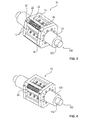
- FIG. 1 is a side view of a schematic representation of a cable 100 and a device 10 for detecting an electrical voltage in an electrical conductor 102 of the cable 100 in a first operating state shown.
- FIG. 2 shows a side view of the cable 100 and the device 10 in a second operating state.
- FIGS. 3 and 4 In each case, a schematic perspective view of the device 10 and the cable 100 is shown, wherein in FIG. 3 the first operating state and in FIG. 4 the second operating state are shown.
- FIG. 5 shows a front view of the cable 100 and the device 10, FIG. 6 another side view.
- the cable 100 comprises an electrical conductor 102, for example a wire, and a jacket 104, which serves in particular for the insulation of the electrical conductor 102.
- an electrical conductor 102 for example a wire
- a jacket 104 which serves in particular for the insulation of the electrical conductor 102.
- the device 10 comprises a housing 12, which has a first housing part 14 and a second housing part 16, which are separable from each other and connectable to each other.
- the two housing parts 14 and 16 are connected to each other, wherein the cable 100 is received in a receiving region of the device 10.
- the receiving area is in particular designed such that the device 10 completely encloses the cable 100 and in particular is non-sliply fastened to it by an interference fit.
- the apparatus 10 includes a display unit 20 having a viewing window 22 through which the operator can see an indication that indicates whether the conductor 102 has a DC current of at least the predetermined threshold current flowing through it.
- a first operating state in which the direct current flowing through the conductor 102 has a current intensity which is less than or equal to the predetermined limiting current intensity. This is indicated by displaying a first display 24 in the viewing window 22.
- This first display is designed, in particular, in the form of a green area, so that the operator intuitively perceives that he / she can safely handle the cable 100.
- a second operating state in which the conductor 102 is traversed by a direct current whose current strength is greater than that is predetermined limit current.
- This is indicated by displaying a second display 26 in the viewing window 22.
- the second display 26 is in the form of triangles with a lightning symbol.
- the second display 26 is designed in the form of a red-colored surface. In either case, the second display 26 intuitively communicates the presence of a hazard.
- a combination of a red-colored area with warning triangles and / or lightning symbols can be used.
- any other first displays 24 and second displays 26 may be used. For example, a predetermined text can also be displayed in each case.
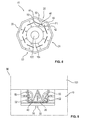
- FIGS. 7 and 8th each show a sectional view through the cross section of the cable 100 and the device 10, wherein FIG. 9 a longitudinal section along the longitudinal axis 30 of the cable 100 shows.
- FIGS. 7 and 9 is the first operating state in which FIG. 8 the second operating state shown.
- the device 10 includes not only a display unit 20 but four display units 20, which are particularly identical in construction.
- the display units 20 are in this case preferably evenly distributed around the circumference of the device 10, so that, regardless of the viewing angle, an operator can read off reliably via the device 10, whether the direct current flowing through the conductor 102 exceeds the limit value or not.
- fewer than four display units 20 or more than four display units 20 may be provided. Likewise, their distribution may be uneven.
- the mode of operation of the display units 20 is explained below by way of example on one of these display units 20.
- the other display units 20 are preferably constructed analogously.
- the display unit 20 comprises a rotation element 40, which is rotatably mounted about a rotation axis 42.
- the rotation element 40 is designed in particular like a plate, and thus comprises a narrow end face 44 and a flat side 46.
- the rotary member 40 is arranged in a first position in which its narrow end face 44 is directed to the viewing window 22.
- a person looking at the viewing window 22 sees the rotation member 40 as merely a narrow strip, as shown in FIG FIG. 1 and FIG. 3 is shown.
- the first position rotation member 40 releases the view of a back side 48 of the display unit 20 in which the first display 24 is located.
- a person looking through the viewing window 22 looks past the rotation element 40 on both sides on the rear side 48 of the display unit 20, which is dyed green.
- the display unit 20 includes two magnets 50, 52 which are formed and arranged to hold the ferromagnetic rotary member 40 in the first position.
- an elastic element for example a spring, may also be used.
- only one magnet 50, 52 or more than two magnets 50, 52 can be used.
- a permanent magnet can also be used.
- the electrical conductor 102 When the electrical conductor 102 is traversed by a direct current, it is surrounded by a magnetic field by which a force is applied to the ferromagnetic rotation elements 40 arranged in it, which force is designed such that it causes a rotational movement of the rotation element 40 about its axis of rotation 42, like this in FIG. 7 and 8th indicated by the arrow P1. If the current intensity of the direct current in the electrical conductor 102 exceeds the predetermined limiting current intensity, the force caused by the magnetic field is greater than the restraining force of the magnets 50, 52, so that when this predetermined limiting current intensity is exceeded, the rotating element 40 is rotated in the direction of the arrow P1, until it is in the in FIG. 8 is shown in the second position shown. The rotation element is rotated in the second position, in particular by an angle of 90 ° relative to the first position.
- the rotation element 40 is arranged such that a person looking through the viewing window 22 sees the flat side 46.
- the rotation element 40 is in particular so wide that the view of the back 48 is completely blocked by it, so that the first display 24 mounted on the back 48 is not visible. Rather, the second display 26 is applied on the flat side 46, so that in the second operating state, a person looking through the viewing window 22 sees this second display 26.
- the device 10 operates purely passive, ie that no separate power supply unit, such as For example, a battery is necessary. Likewise, no direct contact with the conductor 102 is necessary.
- the adjustment of the display unit 20 between the first display 24 and the second display 26 is effected solely by the force caused by the magnetic field of the electrical conductor 102 on the rotary member 40. Thus, a safe low maintenance operation is achieved.
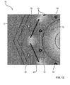
- FIG. 10 is a schematic representation of a simulation of the magnetic field 70, which is generated by the current-carrying conductor 102 and the magnets 50, 52 shown.
- the Figures 11 and 12 each show sections of the magnetic field 70th
- the display units 20 are also designed such that more than just two operating states can be displayed.
- the rotary member 40 and the magnets 50, 52 are in particular designed and arranged so that more than two predetermined positions can be assumed, depending on the current intensity of the DC current flowing through the conductor 102 and corresponding to each other another display 24, 26 through the viewing window 22nd is visible.
Landscapes
- Physics & Mathematics (AREA)
- General Physics & Mathematics (AREA)
- Measurement Of Current Or Voltage (AREA)
- Breakers (AREA)
Applications Claiming Priority (1)
| Application Number | Priority Date | Filing Date | Title |
|---|---|---|---|
| DE201220103577 DE202012103577U1 (de) | 2012-09-18 | 2012-09-18 | Vorrichtung zur Ermittlung eines elektrischen Gleichstroms in einem elektrischen Leiter |
Publications (2)
| Publication Number | Publication Date |
|---|---|
| EP2708904A2 true EP2708904A2 (fr) | 2014-03-19 |
| EP2708904A3 EP2708904A3 (fr) | 2015-07-29 |
Family
ID=49084916
Family Applications (1)
| Application Number | Title | Priority Date | Filing Date |
|---|---|---|---|
| EP13183070.5A Withdrawn EP2708904A3 (fr) | 2012-09-18 | 2013-09-05 | Dispositif de détermination d'un courant électrique continu dans un conducteur électrique |
Country Status (2)
| Country | Link |
|---|---|
| EP (1) | EP2708904A3 (fr) |
| DE (1) | DE202012103577U1 (fr) |
Cited By (1)
| Publication number | Priority date | Publication date | Assignee | Title |
|---|---|---|---|---|
| CN111426870A (zh) * | 2020-05-12 | 2020-07-17 | 南方电网数字电网研究院有限公司 | 导线运行状态检测方法、系统、装置和计算机设备 |
Family Cites Families (13)
| Publication number | Priority date | Publication date | Assignee | Title |
|---|---|---|---|---|
| US1148481A (en) * | 1914-12-10 | 1915-07-27 | Louie Lennig Rowland | Current-indicator. |
| DE1719047U (de) * | 1956-01-11 | 1956-03-22 | Flii Borletti Soc Per Azioni | Strommesser zur anzeige des ladevorganges bei akkumulatorbatterien in kraftfahrzeugen. |
| DE1089883B (de) * | 1958-01-15 | 1960-09-29 | Kjellberg Esab G M B H | Stromrichtungsanzeiger fuer Gleichstromschweissung |
| DE1207493B (de) * | 1962-04-18 | 1965-12-23 | Schoeller & Co Elektrotech | Elektrischer Strom- oder Spannungsindikator nach dem Drehspulprinzip in Kleinstausfuehrung |
| GB1029141A (en) * | 1964-01-10 | 1966-05-11 | Ferranti Ltd | Improvements relating to means for indicating the passage of a fault current along a conductor |
| US3720872A (en) * | 1970-09-04 | 1973-03-13 | Taft Electrosyst Inc | Power transmission fault indicator with automatic reset means |
| CH519757A (de) * | 1971-03-05 | 1972-02-29 | Sprecher & Schuh Ag | Kurzschlussanzeiger |
| JPS613068A (ja) * | 1984-06-18 | 1986-01-09 | Fujikura Ltd | 磁性流体を用いた電流センサ |
| US5341088A (en) * | 1984-06-22 | 1994-08-23 | Davis Murray W | System for rating electric power transmission lines and equipment |
| US4808916A (en) * | 1986-11-14 | 1989-02-28 | Niagara Mohawk Power Corporation | Power supply magnetic shunt for transmission line sensor module |
| US5677623A (en) * | 1996-04-08 | 1997-10-14 | Schweitzer, Jr.; Edmund O. | Fault powered fault indicator having timed reset |
| CA2484957A1 (fr) * | 2004-07-07 | 2006-01-07 | Veris Industries, Llc | Transformateur-pince de detection |
| US8446154B2 (en) * | 2010-09-24 | 2013-05-21 | The Boeing Company | Methods and systems for quantifying degradation of wiring insulation |
-
2012
- 2012-09-18 DE DE201220103577 patent/DE202012103577U1/de not_active Expired - Lifetime
-
2013
- 2013-09-05 EP EP13183070.5A patent/EP2708904A3/fr not_active Withdrawn
Non-Patent Citations (1)
| Title |
|---|
| None |
Cited By (1)
| Publication number | Priority date | Publication date | Assignee | Title |
|---|---|---|---|---|
| CN111426870A (zh) * | 2020-05-12 | 2020-07-17 | 南方电网数字电网研究院有限公司 | 导线运行状态检测方法、系统、装置和计算机设备 |
Also Published As
| Publication number | Publication date |
|---|---|
| DE202012103577U1 (de) | 2013-12-20 |
| EP2708904A3 (fr) | 2015-07-29 |
Similar Documents
| Publication | Publication Date | Title |
|---|---|---|
| EP3303092B1 (fr) | Dispositif de fixation pour la fixation d'un élément de détection à un rail et dispositif de comptage d'essieux | |
| DE4000717A1 (de) | Ueberspannungsableiter | |
| DE102010056006B4 (de) | Verfahren zur Überwachung eines Leitungsnetzes für ein Fahrzeug sowie entsprechende Überwachungsvorrichtung und Fahrzeug | |
| DE69205976T2 (de) | Einrichtung zur positionsangabe von einer leitung oder einem kabel. | |
| EP1239292A2 (fr) | Dispositif pour la mesure de la résistance à la terre | |
| DE102019102419A1 (de) | Vorrichtung zur Bestimmung eines Blattspitzenabstands bei Koaxialrotoren | |
| EP2708904A2 (fr) | Dispositif de détermination d'un courant électrique continu dans un conducteur électrique | |
| DE567906C (de) | Steckvorrichtung mit Schutzkontakt fuer Erdung oder Nullung | |
| DE102013110788A1 (de) | Sammelschienen-Adapter | |
| DE3877729T2 (de) | Anordnung zum erzielen einer kontaktfunktion in einem pruefsystem fuer relaisschutzausruestungen. | |
| DE102009017807A1 (de) | Ionisator | |
| DE102012010848A1 (de) | Anordnung zur induktiven Übertragung elektrischer Energie | |
| DE3527021C1 (en) | Remote voltage tester | |
| DE102014207271A1 (de) | Leiterdraht, Kabel mit einem solchen und Diebstahlschutzsystem | |
| DE2743587A1 (de) | Anschlussvorrichtung mit einem halter fuer eine schmelzsicherung | |
| EP4049347B1 (fr) | Connecteur électrique doté de porte-fusible | |
| EP3351944A1 (fr) | Dispositif adaptateur destiné au raccordement électrique et mécanique d'un compteur d'électricité électronique doté d'un dispositif de fixation et de contact d'un tableau de compteur | |
| DE202008006899U1 (de) | Vorrichtung zum Detektieren von Temperaturen in Bereichen einer technischen Anlage | |
| DE4406734A1 (de) | Vorrichtung zur Signalübertragung zwischen zwei Endstellen | |
| EP1804341B1 (fr) | Dispositif de contact à fiche antidéflagrante | |
| EP2789063B1 (fr) | Dispositif de protection surtensions | |
| EP0665440A1 (fr) | Appareil pour l'indication d'un courant ayant parcouru des conducteurs d'équipement par foudre | |
| EP2023096A1 (fr) | Appareil de mesure doté d'un plombage et procédé destiné à plomber l'appareil de mesure pour un milieu s'écoulant | |
| EP2533218A1 (fr) | Commutateur protégé contre la manipulation et procédé de protection contre la manipulation, notamment pour la surveillance de portes, fenêtre etc. | |
| DE582733C (de) | Vorrichtung zum Anzeigen oder UEberwachen der Temperatur eines Teiles einer elektrischen Anlage |
Legal Events
| Date | Code | Title | Description |
|---|---|---|---|
| PUAI | Public reference made under article 153(3) epc to a published international application that has entered the european phase |
Free format text: ORIGINAL CODE: 0009012 |
|
| AK | Designated contracting states |
Kind code of ref document: A2 Designated state(s): AL AT BE BG CH CY CZ DE DK EE ES FI FR GB GR HR HU IE IS IT LI LT LU LV MC MK MT NL NO PL PT RO RS SE SI SK SM TR |
|
| AX | Request for extension of the european patent |
Extension state: BA ME |
|
| PUAL | Search report despatched |
Free format text: ORIGINAL CODE: 0009013 |
|
| AK | Designated contracting states |
Kind code of ref document: A3 Designated state(s): AL AT BE BG CH CY CZ DE DK EE ES FI FR GB GR HR HU IE IS IT LI LT LU LV MC MK MT NL NO PL PT RO RS SE SI SK SM TR |
|
| AX | Request for extension of the european patent |
Extension state: BA ME |
|
| RIC1 | Information provided on ipc code assigned before grant |
Ipc: G01R 19/15 20060101AFI20150625BHEP |
|
| STAA | Information on the status of an ep patent application or granted ep patent |
Free format text: STATUS: THE APPLICATION IS DEEMED TO BE WITHDRAWN |
|
| 18D | Application deemed to be withdrawn |
Effective date: 20160130 |